When a GNSS signal is lost, plenty of people think about navigation first. An aircraft may find itself deprived of precise position data, vessels may have difficulty determining their location, and vehicles may be forced to use alternative navigation methods.
However, positioning is only part of the story. There is always something much more fundamental behind each navigation signal: time.
As a matter of fact, there exists a whole invisible network of synchronization, without which the functioning of telecommunications networks, power distribution grids, transportation, aviation, and many others would become impossible.
At this very moment, billions of devices around the planet are coordinated through the use of highly accurate timing signals provided by GNSS. This has been one of the most successful inventions of the modern era, though it also remains one of the most overlooked ones.
However, with a growing number of jamming cases and increasing interconnectivity of critical infrastructures, times are changing. Today, the question is not whether companies need highly accurate timing, but how long they can operate without it.
The World’s Most Invisible Dependency
Timing rarely receives the same attention as positioning, yet it underpins many of the systems society depends upon daily.
A mobile phone call connects because cellular networks remain synchronized. A financial transaction gets verified based on the system’s agreement on the accurate sequence of events. Electrical power can flow effectively from one country to another due to the shared timing reference point among substation and control centers.
Aviation technology cannot ignore this either. Today, this field requires synchronized surveillance, communications, navigation, and operation systems. There are millions of interconnected processes at the airport, and they require timing for safety reasons.
Emerging technologies, such as digital towers and more advanced air mobility systems, are becoming more reliant on the synchronization process. In most cases, for instance, GPS is used for its unmatched accuracy and accessibility.
The challenge now is that dependence often breeds complacency.
When Time Stops
Contrary to a total breakdown, timing disruptions tend to be more subtle.
A network can function while synchronization slowly becomes poor. A communication system can be working without issues while performance slowly declines. Timing disruption goes unnoticed by critical infrastructure operators until they discover that the common reference connecting various systems is no longer effective.
It is because of this that timing disruption poses such a serious threat. Any small timing issue may rapidly spread across connected systems. Milliseconds can turn into seconds, whereas localized disturbances may quickly become network-wide issues. Depending on which industry sector is being considered, consequences may include reduced performance or even total disruption.
As GNSS interference increases, this trend will only accelerate.
Various instances of increased GNSS jamming and spoofing have already been recorded within aviation in Europe, the Middle East, and other parts of the world. Although all focus has been on navigation issues, the bottom line remains the same: if GPS signals are jammed or spoofed, so can timing signals be.
Resilience Is the New Accuracy
While accuracy has always been the main priority in the past several decades, nowadays, it starts being accompanied by resilience. Even the best timing solution in the world means nothing when it proves unreliable in case of any disruptions.
As a result, today’s operators of critical infrastructure are changing their approach to timing, no longer focusing solely on accuracy. The target is to maintain reliable timing under any circumstances, including the presence of adversarial attacks or other forms of interference.
Such an approach affects the design of the timing architecture itself, which in the future will likely become more complex and rely on multiple timing sources. GNSS systems will remain integral, while other elements, such as atomic clocks or resilient PNT technologies, will complement them.
In other words, the future is no longer entirely about redundancy but about reliability.
The Rise of Assured Timing
Assured PNT is a term that has received considerable attention in recent years, especially among companies working in aviation, military, telecommunication, and energy fields. Its essence is clear and straightforward: companies should not depend completely on one source of time signal.
On the contrary, robust systems need to continuously verify received data, identify irregularities, and continue functioning without the presence of any reliable time references. In other words, the system is intelligent enough to distinguish between correct and incorrect information.
The matter is crucial given the current trend toward automation in different industries.
Automation implies autonomous vehicles, sophisticated air traffic management systems, digital communications infrastructure, and energy distribution networks, all depending on precise timekeeping. Automation, however, doesn’t tolerate uncertainties.
In high-speed decision-making processes, synchronization becomes highly important. Otherwise, the notion of autonomy remains just a fiction.
Building the Next Generation of Resilient Infrastructure
The silver lining in this is the fact that the industry has responded to this challenge.
Investments in robust timing solutions are increasing across the aerospace and critical infrastructure industry. Firms working on developing navigation, timing, and inertial system solutions are now developing technology-based solutions that are capable of ensuring accuracy irrespective of whether the GNSS solution is available or not.
These include solutions around advanced atomic clocks, robust PNT solutions, and signal authentication and monitoring solutions that are capable of detecting any form of interference even before it affects the process.
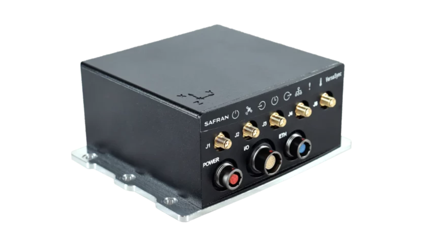
Organizations such as Safran have played an active role in this journey by backing the development of technology that enables infrastructure operators to maintain accurate PNT capability.
The objective is not to replace GNSS. Rather, it is to ensure that critical systems remain operational when GNSS alone is no longer enough.
The Strategic Importance of Time
The importance of timing will only increase in the years ahead.
5G and future communications networks require tighter synchronization. Autonomous transportation systems depend on coordinated decision-making. Smart grids must balance increasingly dynamic energy flows. Aviation continues its journey toward more connected and digitally integrated operations.
Every one of these developments places greater value on resilient timing. For decades, timing has quietly powered the systems behind modern life. It has been so reliable that many organizations have treated it as a given. That assumption is beginning to change.
The future of critical infrastructure will not be defined solely by how accurately systems can determine their position. It will be defined by how effectively they maintain trust when their primary sources of information are challenged.
Because in a world built on synchronization, timing is more than a technical requirement. It is a strategic asset. And when it is lost, the consequences can be felt far beyond the systems that depend on it.
New algorithm cuts indoor positioning error by nearly half
Conventional indoor positioning often depends on expensive Wi-Fi or Bluetooth infrastructure, or on inertial sensors that accumulate drift within seconds. Magnetic navigation has emerged as a promising alternative because steel structures and electronics leave buildings with unique, location-specific magnetic signatures.
However, existing map-free methods rely on polynomial models that oversimplify the magnetic field’s spatial variations. They capture the broad trend but miss the sharp, local anomalies caused by metal pipes or distribution boxes.
With these limitations, a more accurate, robust, and physically interpretable approach to magnetic field modeling is urgently needed for practical indoor navigation.
A team from the Aerospace Information Research Institute, Chinese Academy of Sciences, publishing (DOI: 10.1186/s43020-026-00201-3) in the journal Satellite Navigation on June 5, has unveiled a robust magnetic-inertial odometry (MIO) method based on the Fibonacci sphere-sampled equivalent magnetic dipole model, denoted as FSS-EMD-MIO. The system uses an array of 30 small magnetometers and an inertial measurement unit to track movement without any external signals.
The core innovation lies in how the system models the indoor magnetic environment. Instead of drawing smooth curves through the data, it represents the local field as a combination of virtual “equivalent magnetic dipoles” — with 16 dipoles identified as optimal through systematic parameter analysis.
Their positions are determined by the Fibonacci sphere sampling technique, which evenly distributes points in 3D space without any directional bias, preventing overfitting. Each dipole’s magnetic moment is then solved in real time using least squares fitting.
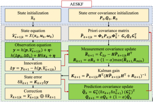
The team also derived the spatial gradient of this model, creating a direct mathematical link between changing magnetic readings and the carrier’s displacement, velocity, and attitude. To handle the inherent nonlinearity and location-dependent noise, an adaptive error state Kalman filter fuses inertial data with magnetic observations. Tested on a public dataset, the method achieved a horizontal positioning root mean square error below 1.27 meters, outperforming the previous state of the art (MAINS) by 46% on average.
“The old polynomial methods look at the magnetic field from far away — they see the hills but not the potholes. Our model places virtual sources exactly where the magnetic perturbations live,” the authors explained. “The Fibonacci sphere sampling ensures that no direction is favored, so whether you tilt the sensor or walk in circles, the system adapts reliably. We essentially gave the building’s chaotic magnetic field a readable 3D structure. This means first responders or warehouse robots can finally have a ‘magnetic compass’ that works even when the lights are off and GNSS is out.”
The research paves the way for truly infrastructure-free indoor navigation. Potential applications include guiding firefighters through smoke-filled buildings, tracking inventory robots in steel-racked warehouses, and providing positioning for autonomous vehicles in parking garages or mines. The authors note that future work will incorporate loop-closure detection to correct long-term drift, akin to how a person recognizes a familiar intersection.
By developing scan-matching algorithms based on overlapping magnetic field regions, the team aims to build a complete magnetic simultaneous localization and mapping (SLAM) system for multi-floor buildings, further closing the gap between outdoor and indoor navigation reliability.
The companies will explore the potential to provide optimal products and solutions by combining Murata’s long-standing expertise in high-frequency and wireless communications, sensors, timing devices and module design with Xona’s advanced low-Earth-orbit (LEO)-based positioning and timing synchronization technologies.
Benefit of LEO satellites
Because LEO satellites orbit closer to Earth, they can deliver stronger signals to the ground, which improves signal reception in city centers and indoor environments. Their higher orbital speed compared with GNSS enables observation data in a shorter period of time, which enhances performance in urban areas via accelerated convergence times and reduction in multipath errors.
Against this backdrop, technologies that combine satellites in different orbital layers, including LEO, are attracting attention as an approach to complement and strengthen the accuracy and reliability of PNT, with growing interest in their adoption for higher precision and enhanced resilience.
The role of Pulsar
Xona offers Pulsar, a PNT service based on a satellite network composed of a constellation of dedicated LEO satellites with significantly stronger signals than traditional GNSS systems. Pulsar is compatible with GNSS, enabling these enhanced capabilities to be integrated with typical GNSS user equipment in a way that complements and improves existing systems.
As a purpose-built modern PNT service, Pulsar aims to achieve centimeter-level positioning accuracy, greater performance in urban areas, and enhanced resilience against jamming and spoofing.
Previous venture and latest MOU
Murata has previously invested in Xona through Wonderstone Ventures, Murata’s corporate venture capital arm. This initiative represents part of an ongoing collaboration built upon the existing relationship between the two companies.
Based on this MOU, the two companies will explore the potential to provide optimal products and solutions by combining Murata’s long-standing expertise in high-frequency and wireless communications, sensors, timing devices, and module design with Xona’s advanced LEO-based PNT positioning and timing synchronization technologies, with the goal of realizing highly accurate and highly reliable positioning and timing synchronization.
Looking ahead, the companies will evaluate potential applications in data centers and financial institutions that require highly accurate timing synchronization to support 5G/6G communications, as well as in off-road industries such as construction and agricultural machinery, where positioning needs are high in environments where GNSS is difficult to use.
Through these efforts, the companies aim to enhance performance and create new solutions across various sectors.
The National Association of Broadcasters (NAB) has launched Merkhet Solutions, an independent company focused on the commercial deployment of the Broadcast Positioning System (BPS).
BPS, first conceived by the technology team at NAB in 2021, is a patented terrestrial, GPS-independent timing and positioning technology that leverages the high-power, geographically diverse broadcast infrastructure already covering the United States.
BPS has been designed to address the more than $1 billion-per-day economic and national security risk posed by overreliance on GPS. Merkhet Solutions is engaging across critical infrastructure sectors, including energy, data centers, telecommunications and financial services – where a loss of precision time can trigger grid instability, outages and lost trades.
“BPS represents a powerful intersection of innovation, public safety and opportunity for broadcasters,” said NAB President and CEO Curtis LeGeyt. “Launching Merkhet Solutions is the next step in commercializing this technology and ensuring it reaches the critical-infrastructure operators who need it most, while continuing to create meaningful long-term opportunities for local stations.”
“BPS solves a problem we can no longer afford to ignore: an entire economy and national security posture resting on a single, contested signal from space,” said Merkhet Solutions CEO Sam Matheny. “We built BPS at NAB because broadcast infrastructure is uniquely suited to deliver assured terrestrial timing at scale. We’re launching Merkhet Solutions because the time to operationalize this technology is now.”
Under Matheny’s leadership at NAB, BPS has advanced rapidly from research concept to real-world deployment. NAB demonstrated the first BPS prototype to the U.S. Department of Transportation (DOT) in 2022, followed by the first live broadcast demonstration in 2023.
In 2024, NAB entered into a Cooperative Research and Development Agreement (CRADA) with the National Institute of Standards and Technology (NIST) and Nexstar Media Group. In 2025, NIST concluded in a peer-reviewed paper presented at the Institute of Navigation International Technical Meeting that BPS was “comparable to or better than GNSS” for time transfer stability and a “viable complementary PNT solution.”
Later that year, the U.S. DOT awarded NAB a contract to deploy a BPS field trial with critical-infrastructure partner Dominion Energy.
BPS is designed as a terrestrial complement to GPS, providing operators with an additional resilient source of timing and positioning that can be used alongside GPS or relied upon when satellite-based services are disrupted by jamming, spoofing, cyberattacks or natural events. The need for terrestrial complements to GPS has been recognized by the U.S. government through the National Timing Resilience and Security Act and Executive Order 13905.
A two-kilometer free-space demonstration validates quantum-secure communications and resilient PNT capabilities
Xairos Systems has met a significant milestone for its Ares Quantum Optical Terminal, a robust system designed to deliver quantum-secure, high-data-rate communications and resilient position, navigation and timing (PNT) in RF- and GPS-denied environments.
The Ares terminal will combine 10 Gbps free-space optical communications, entangled photon distribution for timing and encryption key sharing, and a stable clock ensemble disciplined by Xairos’ exclusive Quantum Time Transfer technology.
Xairos completed two-kilometer free-space range testing with Space Development Agency-compliant optical communications and established simultaneous quantum and optical links using a common Ares Quantum Optical Terminal. This free-space testing — distinct from fiber-based demonstrations — marks a critical step toward real-world operational deployment.
The fully integrated Ares Quantum Optical Terminal will combine 10 Gbps free-space optical communications, entangled photon distribution for timing and encryption key sharing, and a stable clock ensemble disciplined by Xairos’ Quantum Time Transfer (QTT) technology — all within a ruggedized compact package. QTT provides unprecedented security and resilience for PNT where GPS and RF signals are unavailable or jammed.
The Ares Quantum Optical Terminal underpins a communications and PNT mesh network for aircraft, uncrewed aerial systems (UAS), ships, and other assets in contested environments, and serves as a foundation for a future space-based architecture spanning satellites, air vehicles and ground nodes.
Developed for a U.S. Army Program of Record, the TRX DAPS GEN II solution provides warfighters with a resilient, trusted source of position, navigation and timing (PNT) that remains operational in GPS-degraded, jammed or denied environments.
The new enhancements strengthen DAPS GEN II system performance in extended-duration threat environments and include a new mounted capability that facilitates vehicle integration.
The new mounted capability delivers a modular, open architecture that expands client support and provides future extensibility while leveraging the core DAPS GEN II capability. To facilitate use of DAPS GEN II in vehicles, a vehicle interface adapter (VIA) is under development to provide the following capabilities:
Hold the DAPS GEN II device securely in the vehicle, enabling improved inertial performance under threat
Accept and condition power from the vehicle, extending battery life
Extend the number of supported clients, enabling vehicle systems to consume a single assured-PNT feed
Provide RF and data interfaces to anti-jam antennas, enabling tight integration with the antennas, including sharing of electronic warfare situational awareness information
Provide a FLEX-IO port, enabling extensibility by supporting addition of new PNT sensors and simplifying transition of new assured PNT capabilities
JNC 2026 attendees can visit the TRX team in Booth #319 to learn how the DAPS GEN II solution supports dismounted and mounted operations by delivering continuous, assured PNT – even in contested environments.
During the conference, TRX leaders will participate in technical sessions where they will discuss the latest DAPS GEN II innovations and share testing results for delivering assured PNT in both dismounted and mounted situations:
Session C6 (Tuesday, 11:30 a.m.): Speakers from TRX Systems and Combat Ready PNT will present U.S. Army Program of Record: DAPS Gen II Advancements, Interoperability, and Performance. This presentation will review DAPS GEN II innovations that increase resilience to extended-duration threats.
Session C6: TRX Systems is supporting an alternate presentation,U.S. Army Program of Record DAPS Mounted ECP (DME). This presentation will cover the functionality being developed with the VIA and provide results from the development and testing.
TrustPoint has been awarded a $4 million Tactical Funding Increase (TACFI) contract to demonstrate a GPS-independent positioning, navigation and timing (PNT) system.
The award was issued by SpaceWERX, the innovation arm of the United States Space Force, and jointly funded by the Small Business Innovation Research (SBIR) program and the Commercial Space Office (COMSO). It supports a full end-to-end demonstration of TrustPoint’s resilient navigation architecture designed for defense and commercial applications.
Under the contract, TrustPoint will design, deploy and operate a fully integrated PNT system comprising four satellites and four ground stations, delivering a complete operational architecture. The program will execute an end-to-end system demonstration, including live trilateration across multiple space and ground assets, operational services and advanced receivers.
With an accelerated execution timeline, initial system deployments will occur within 12 months, establishing a rapid deployment model designed to scale to significantly larger constellations while prioritizing affordability, operational relevance, and capital efficiency.
“We founded TrustPoint on the belief that resilient navigation does not require billion-dollar constellations,” said Patrick Shannon, founder and CEO of TrustPoint. “This program will prove our technology’s GPS independence while demonstrating that real, operational PNT capability can be delivered with exceptional capital efficiency.”
Beyond GPS-independent C-band demonstrations, the system will validate a software-defined architecture that supports on-demand reconfiguration of navigation services in contested, degraded and denied environments, pioneering commercial delivery of this capability. TrustPoint’s experience includes the first C-band GNSS signal transmission with real-time reception and the first broadcast-based ground-to-space C-band PNT demonstration.
The program directly advances national security objectives. It also establishes a scalable foundation for future commercial services, redefining what is possible for users who require reliable PNT in GPS-challenged environments.
ArkEdge Space Inc. has completed a study commissioned by the Japan Aerospace Exploration Agency (JAXA) on “Elemental Technologies and Systems for a Dedicated, GNSS-Independent LEO-PNT Satellite System.”
Positioning, navigation and timing derived from GNSS is increasingly subject to interruption and interference, both through environmental and security challenges. Finding methods to protect PNT information against such interference is of paramount importance for governments and commercial actors alike.
The ArkEdge/JAXA project addressed such challenges by examining and categorizing the necessary elemental technologies — signal design, receiver technology, ground infrastructure, satellite sensors, and the overall system architecture — required to realize a LEO-PNT system capable of providing PNT without reliance on traditional GNSS.
The study’s focus included achieving satellite orbit determination and time synchronization without GNSS, one of the key challenges facing alternative PNT providers. It explored a new architecture for onboard time determination that avoids the need for large atomic clocks. Instead of onboard clocks, the system transmits precise timing information from combinations of ground-based reference clocks, pseudolites and inter-satellite optical links to disseminate information and enable on-orbit ODTS.
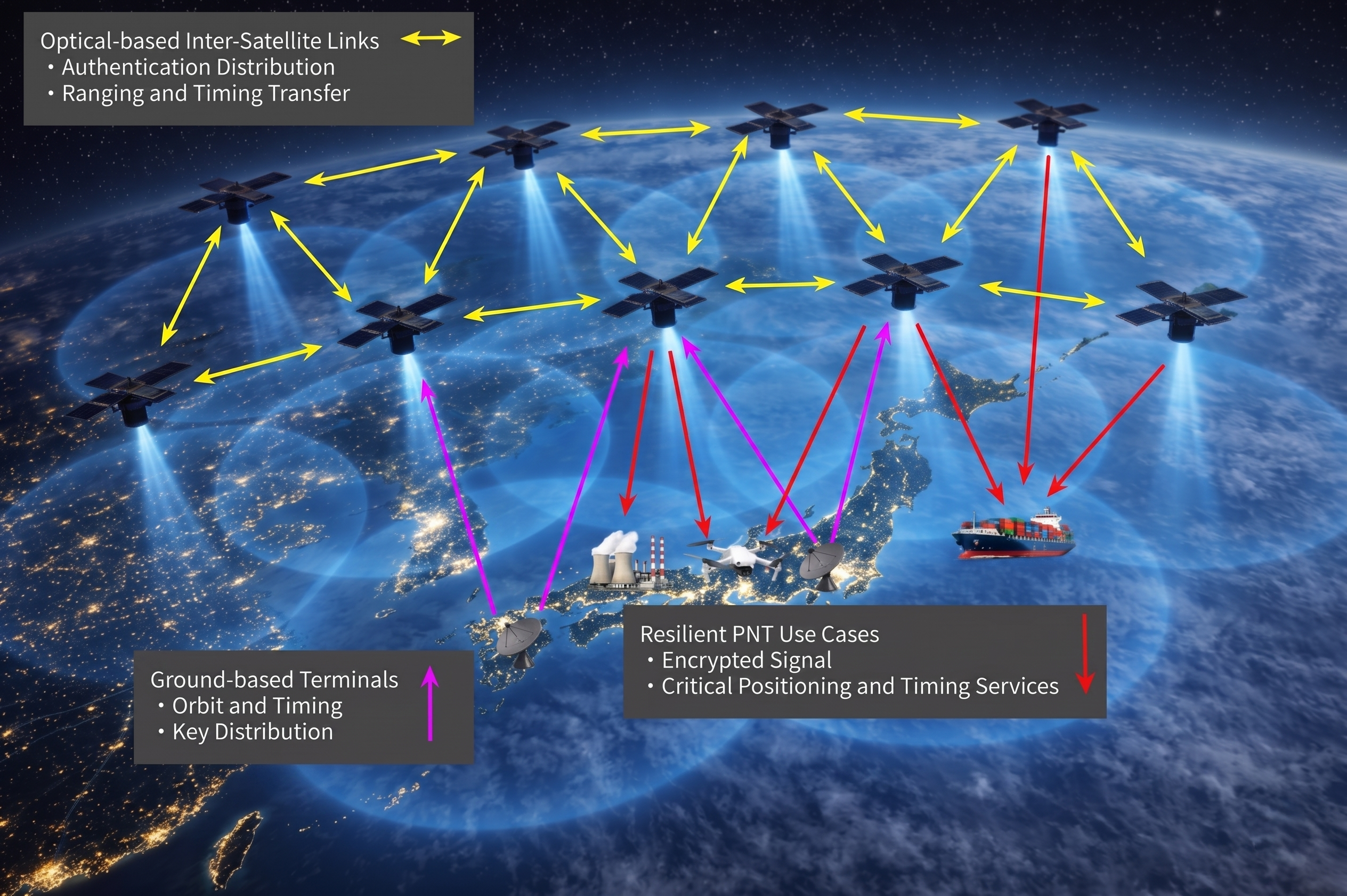
Concept art of the LEO-PNT satellite constellation. (Credit: ArkEdge Space)
The study considered diverse frequencies to strengthen anti-jamming measures. It also looked at novel signal design, receivers, encryption and signal authentication methods, and their suitability for LEO-PNT satellites. Results of the study will contribute to the next stage of development for a GNSS-independent LEO-PNT concept.
“This study is critical to advancing our understanding of Japan’s future relationship with PNT,” said ArkEdge Space Chief Strategy Officer Tomoaki Yasuda. “Across the world, users are facing denial of GNSS services, and that can have critical consequences for sectors including the economy, transport and emergency services, among others. We look forward to progressing the GNSS-independent LEO-PNT concept with the support of our partners.”
“Due to the prevalence of GNSS interference, alternative PNT systems are becoming increasingly important to protect users and assets such as critical national infrastructure,” said Masaya Murata, JAXA. “Following the successful conclusion of this GNSS-independent LEO-PNT study with ArkEdge Space, our investigation into a robust and resilient LEO-PNT system continues. We are also emphasizing international cooperation with other LEO-PNT providers to maximize users’ PNT experience and continue to engage in collaborative discussions.”
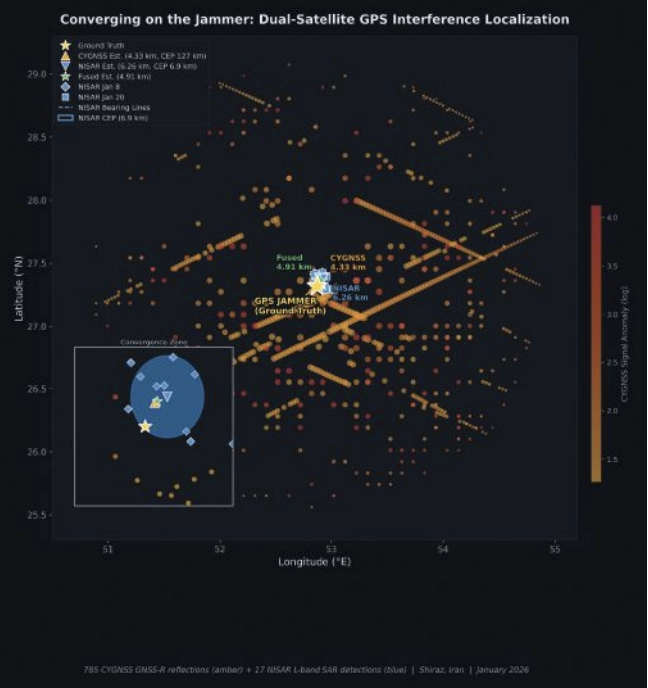
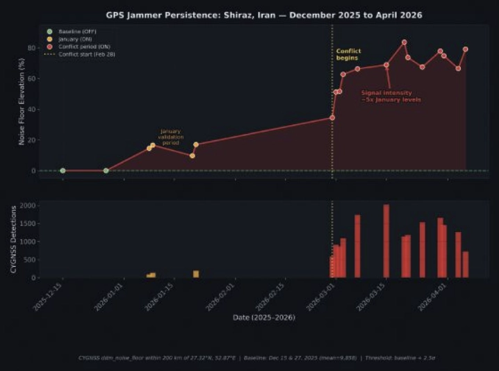
On a January morning in 2026, a GPS jammer powered up near Shiraz, Iran. It was not the first, and it would not be the last. The Strait of Hormuz corridor has become one of the most persistently jammed airspaces on Earth. But this time, two satellites were watching from very different vantage points, and together they would demonstrate something new: that spaceborne sensors can localize a terrestrial GPS jammer to within a few kilometers, using physics alone.
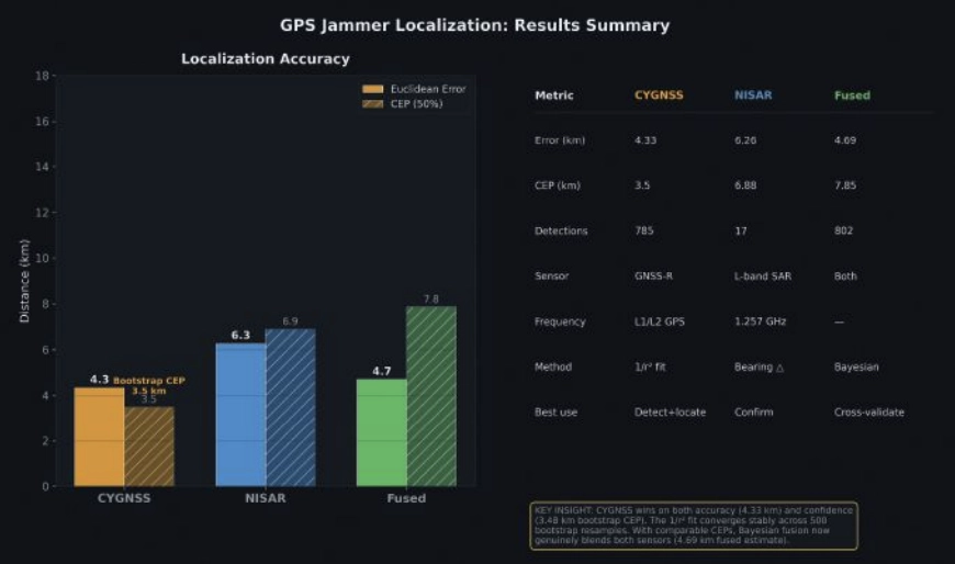
This article presents the first direct comparison of Cyclone Global Navigation Satellite System (CYGNSS) — a NASA GNSS reflectometry constellation — and NASA-ISRO Synthetic Aperture Radar (NISAR) — an L-band synthetic aperture radar for GPS jammer localization. The results challenge assumptions about which modality performs better and reveal that the answer depends on a question most analysts forget to ask.
The setup: Known jammer, known position
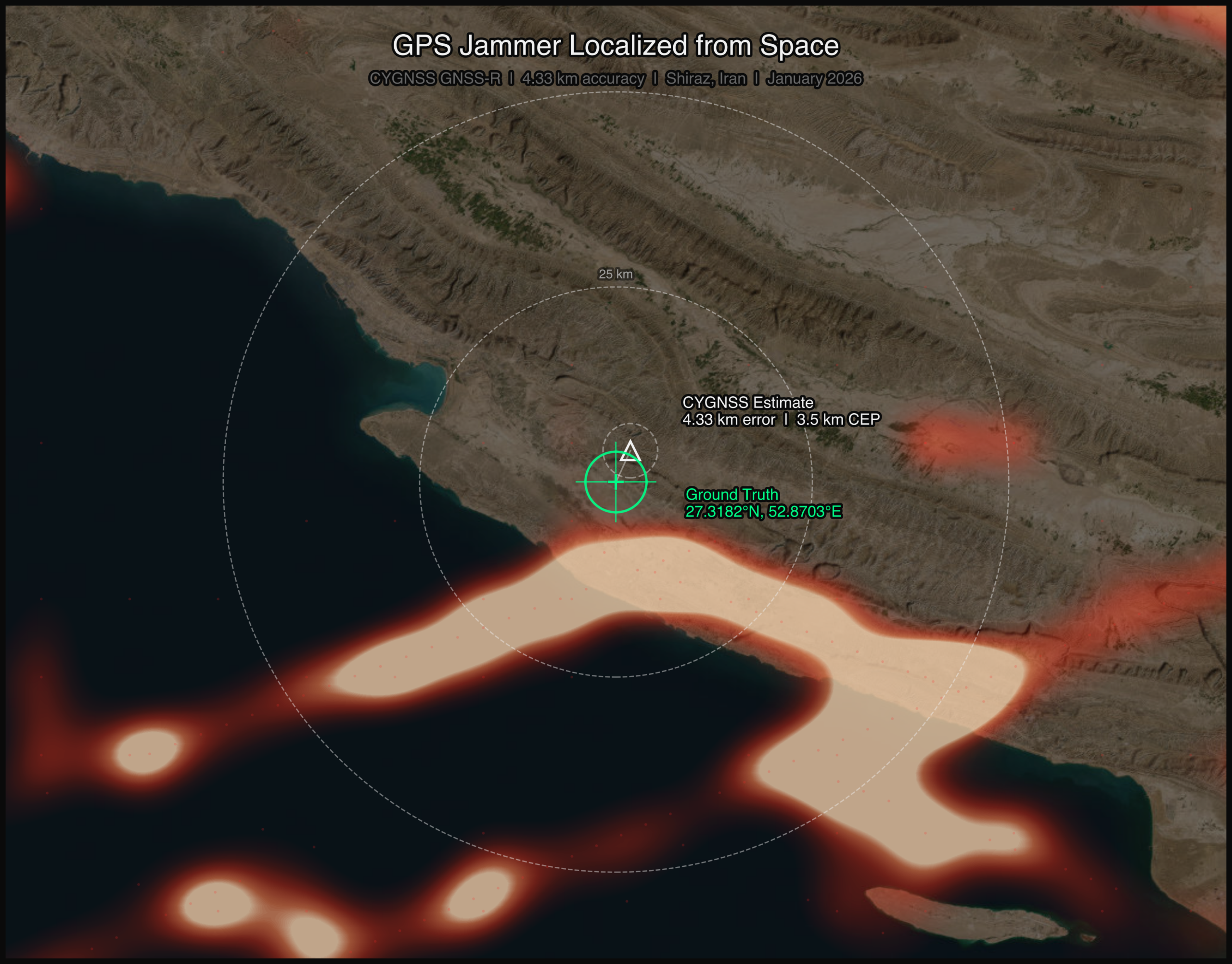
Validation requires ground truth. With help from the PNT community, we identified a GPS jammer operating near 27.32°N, 52.87°E (approximately 50 km southwest of Shiraz) that was active on Jan. 8 and Jan. 20, 2026, with confirmed quiet periods on Dec. 15 and Dec. 27, 2025. The jammer’s position was established through independent signals intelligence.
This gave us a controlled experiment: two “jammer ON” dates and two “jammer OFF” baseline dates, with satellite coverage from both CYGNSS and NISAR spanning the full period.
Two satellites, two physics
CYGNSS is a constellation of eight microsatellites that measure GPS signals reflected off Earth’s surface. Each spacecraft carries a delay-Doppler receiver that maps reflected signal power across a grid of delay and Doppler bins, known as the delay-Doppler map, or DDM. When a terrestrial jammer is active, it floods the GPS band with noise, elevating the DDM noise floor and suppressing the coherent surface reflection. The effect is detectable hundreds of kilometers from the jammer, creating a wide-area footprint in the reflected signal data.
FIGURE 1 Jammer localization tracks from both CYGNSS and NISAR satellite constellations. (All figures by Sean Gorman)
NISAR operates an L-band SAR at 1.257 GHz, just 30 MHz from the GPS L2 frequency at 1.2276 GHz. When a GPS jammer’s broadband emissions leak into NISAR’s receive band, they create characteristic streaks in the SAR imagery. The streaks are elongated in the cross-track (range) direction, not along-track, a counterintuitive result that follows directly from SAR signal processing. In azimuth (along-track), the jammer is a fixed-point source with a valid Doppler history, so the SAR azimuth processor focuses it correctly, similar to any ground target. But in range (cross-track), the jammer’s broadband noise does not match the SAR’s chirp waveform, so range compression smears the energy across many range bins rather than compressing to a point. The result is a streak perpendicular to the flight direction, whose along-track centroid encodes the jammer’s latitude and whose cross-track extent encodes a range arc, which is the distance from the orbit ground track (FIGURE 1). The bearing of each streak encodes the jammer’s direction relative to the satellite’s ground track.
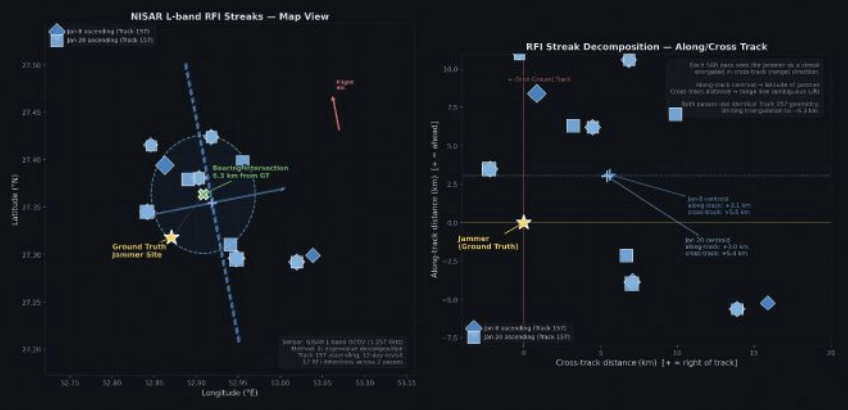
FIGURE 2 Crosstrack visualization for NISAR RFI streaks.
The two sensors could hardly be more different. CYGNSS sees the jammer’s effect on reflected GPS signals, offering an indirect measurement spread across hundreds of specular reflection points. NISAR sees the jammer’s emissions directly in its own receiver, which is a more precise measurement, but only along the satellite’s narrow ground track. FIGURE 2 shows both detection sets converging on the jammer location.
CYGNSS: 785 Detections, 4.33 km Error
We processed all CYGNSS Level 1 data within 200 km of the jammer location on both ON and OFF dates. Four detection methods contributed observations:
■ DDM noise floor (419 detections): The pre-computed ddm_noise_floor variable, calibrated against the thermal noise reference, proved the strongest discriminator. Near-jammer values exceeded 15,000 counts against a ~10,000 mean background.
■ Spatial noise grid (299):A 10 km gridded analysis identified cells with anomalously elevated noise relative to adjacent cells.
■ SNR hole detection (66): Coherent surface reflections were suppressed near the jammer, creating spatial “holes” in the SNR field.
■ NBRCS drop (1): Surface reflectivity dropped approximately 16% near the jammer, though this method produced few threshold exceedances.
Across four DDM channels per spacecraft and multiple passes, this yielded 785 total anomalous observations on the jammer-ON dates.
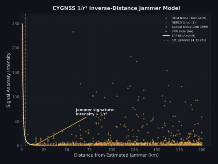
FIGURE 3 Scatterplot of interference insensity versus distance for CYGNSS.
Localizing using a simple centroid of all 785 detection positions placed the jammer 32.1 km from truth, with too many distant, low-SNR detections diluting the estimate.
Instead, we fit a parametric 1/r² inverse-distance model:
I(r)=Ar2
where A is a free amplitude parameter and r is the distance from a candidate jammer position. We jointly optimized the jammer position and amplitude using SciPy’s Nelder-Mead optimizer across all 785 observations, weighted by intensity. The optimizer converged on a position 4.33 km from ground truth, providing a 27.7 km improvement over the centroid (FIGURE 3).
The baseline: Zero false positives
On the jammer-OFF dates (Dec. 15 and Dec. 27, 2025), the pipeline produced exactly zero detections using the same thresholds, geographic area and satellites: a completely clean result. This suggests that the 785 detections are unlikely to be sensor artifacts or geographic anomalies. They disappear when the jammer turns off.
NISAR: 17 Detections, 6.26 km Error
NISAR’s approach is fundamentally different. Rather than measuring hundreds of reflected signals across a wide area, it captures direct emissions in a narrow swath, but with far greater geometric precision.
We processed NISAR L2 GCOV (geocoded covariance) products from Track 157, Frame 15 (ascending) for three dates: the Dec. 27 baseline and the Jan. 8 and Jan. 20 jammer-ON passes. The detection pipeline used eigenvalue decomposition of the polarimetric covariance matrix:
λ₁ ratio thresholding: In jammer-contaminated pixels, the dominant eigenvalue λ₁ of the 2×2 [HH, HV] covariance matrix rises sharply relative to the scene mean, indicating an unpolarized additive source.
Cross-polarization ratio (HV/HH): GPS jammer emissions are unpolarized, disproportionately elevating the HV channel. Anomalous HV/HH ratios flag contaminated azimuth lines.
Iterative outlier trimming: Three rounds of 1.5σ clipping removed scattered false detections, leaving 17 high-confidence streak centroids.
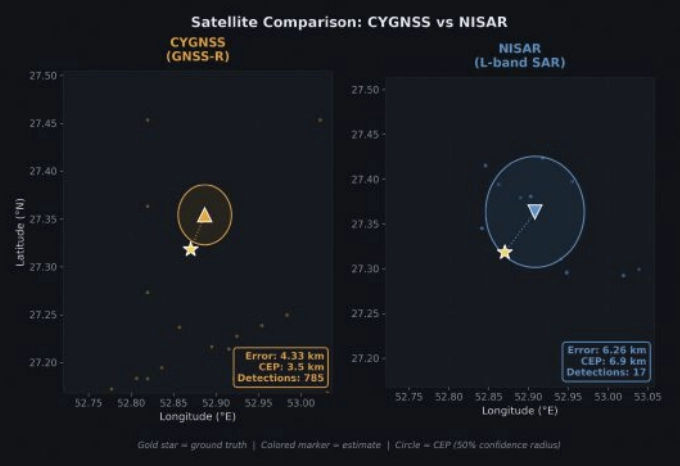
FIGURE 4 Error and CEP Metrics Comparison for CYGNSS and NISAR.
With detections from two passes on different dates, we had two independent bearing lines. Each pass’s streak centroids defined an azimuth aligned cluster whose major axis pointed toward the jammer. A PCA fit to the two clusters extracted the bearing: 308.1° from the Jan. 8 pass and 316.2° from Jan. 20. Their intersection — computed via scipy optimization of the angular residual — landed 6.26 km from ground truth (FIGURE 4).
The along-track/cross-track decomposition reveals why the 6.26 km error is a geometric ceiling for this dataset, not a processing limitation. Both passes come from the same Track 157 ascending orbit on a 12-day repeat cycle. The intensity-weighted along-track centroids land at +3.0 km and +3.1 km north of the jammer, a direct stable latitude measurement. The cross-track centroids land at +5.4 km and +5.6 km east of the orbit ground track, a range measurement. But because both passes share identical orbit geometry, the two range arcs are nearly parallel. The bearing difference between passes (308.1° vs 316.2°) is only 8.1°, producing a shallow intersection angle and poor cross-range resolution. A single descending pass, which would cross the ascending track at approximately 60-70°, would transform the geometry from two near-parallel lines to a genuine triangulation, potentially reducing the localization error to sub-2 km. Unfortunately, no descending NISAR pass covering this jammer site was available in the beta archive, which ends on Jan. 20, 2026.
The CEP (circular error probable, the radius containing 50% of repeated estimates) was 6.88 km, meaning if we ran this analysis on many similar jammers, half our estimates would fall within ~7 km.
Who wins?
CYGNSS wins, and not just on accuracy.
A naive confidence metric for the 1/r² fit would be the scatter of the 785 input detections (CEP = 127 km). But the detections are not the estimate; they are the inputs to a model fit. The relevant confidence question is: How stable is the fitted position?
We answered this with a 500-iteration bootstrap: resample the 785 detections with replacement, re-run the 1/r² optimizer each time and measure the spread of the resulting position estimates. The bootstrap CEP, the median radial distance across 500 fitted positions, was 3.48 km. The optimizer converges stably to within a few kilometers of the same location regardless of which detections are included.
This means CYGNSS achieves 4.33 km error with 3.48 km confidence, both better than NISAR’s 6.26 km error and 6.88 km confidence.
The bootstrap CEP also reveals what the raw scatter obscures: the 1/r² fit is constrained primarily by the ~80 high-intensity detections within 30 km of the jammer. The remaining 700 distant, low-intensity detections contribute little to the position estimate — they are correctly downweighted by the intensity-weighted least squares. The fit’s stability comes from the physics: a 1/r² signal has steep gradients near the source, providing strong positional constraints where it matters most.
Bayesian fusion: Can we get both?
The obvious next question: Can we combine CYGNSS’s wide-area sensitivity with NISAR’s geometric precision? We implemented four fusion strategies, all designed to work without ground truth:
■ Bayesian Gaussian posterior: Model each sensor’s estimate as a 2D isotropic Gaussian with σ = CEP/1.1774. The posterior is the product of the two Gaussians: an analytical precision-weighted mean.
■ NISAR-prior constrained 1/r²: Re-run the CYGNSS optimizer with a Gaussian regularization term pulling toward the NISAR estimate, sweeping the regularization weight λ from 0.01 to 10.
■ NISAR-proximity re-weighted 1/r²: Apply a Gaussian kernel centered on the NISAR estimate to the CYGNSS detections before fitting, effectively upweighting observations consistent with the SAR result.
■ Joint CEP-balanced: Combine the CYGNSS gradient signal with NISAR cluster proximity, weighted by (σ_CYGNSS/σ_NISAR)².
FIGURE 5 Summary statistics for jammer localization with CYGNSS, NISAR and fused approach.
With the bootstrap CEP, the precision ratio flips. The CYGNSS Gaussian (σ = 2.95 km) is now 2× tighter than NISAR (σ = 5.84 km). The Bayesian posterior, the precision-weighted mean, lands at 4.69 km, pulling toward CYGNSS’s better estimate while incorporating NISAR’s independent geometric constraint. FIGURE 5 shows the fusion: two comparable Gaussians whose product is tighter than either alone.
The fused result (4.69 km error, 7.85 km CEP) is not quite as accurate as CYGNSS alone (4.33 km), because NISAR’s 6.26 km estimate pulls it slightly away from truth. But operationally, the fusion provides a cross-validated answer: two independent physics arriving at similar locations builds confidence that neither sensor is producing an artifact.
The key insight is that the bootstrap CEP unlocked meaningful fusion. When the raw scatter CEP (127 km) was used, NISAR dominated the posterior 343:1 and fusion added nothing. With the fit-based CEP (3.48 km), both sensors contribute, and the posterior reflects genuine multi-modal evidence.
Operational implications
For CYGNSS: CYGNSS excels at both detection and localization. Its 785 detections across a 200 km radius, with zero false positives on baseline dates, provide unambiguous jammer detection. The 1/r² fit achieves 4.33 km accuracy with a bootstrap-verified 3.48 km CEP, meaning an analyst can trust the result to single-digit kilometer precision without ground truth. CYGNSS’s eight-satellite constellation also provides sub-daily revisit, enabling near-real-time monitoring.
For NISAR: NISAR provides independent geometric confirmation. With just two passes over an active jammer, the bearing intersection achieved 6.26 km accuracy with a 6.88 km CEP. The 6.26 km result is constrained by orbit geometry, not by detection sensitivity. Our two ascending passes from Track 157 produced nearly parallel range arcs with only 8.1° of bearing separation. Adding a single descending pass would provide a crossing angle of 60° to 70° and could reduce localization error to sub-2 km — transforming NISAR from a confirming sensor into a precision localization tool in its own right. The limitation in this study was data availability: The NISAR beta archive contained only ascending Track 157 passes over the jammer site. NISAR’s 12-day repeat cycle and fixed ground track also mean the jammer must be active when the satellite passes overhead. NISAR’s current value is as a confirming sensor — when both modalities converge on the same location, confidence increases beyond what either achieves alone.
For Fusion: With comparable CEPs (3.48 km vs 6.88 km), fusion now produces genuinely blended estimates. The Bayesian posterior at 4.69 km reflects real multi-sensor information. Future improvements, such as more NISAR passes with diverse bearings or CYGNSS multi-week accumulation, would tighten both estimates further.
For the Adversary: These results demonstrate that GPS jammers operating in contested airspace are observable and localizable from orbit using openly available civilian satellite data. The 4.33 km CYGNSS result is approximately 2× better than the published state of the art for GNSS-R jammer localization (~9 km grid resolution, Chew et al., 2023) and the NISAR bearing intersection approach has not been previously demonstrated for jammer geolocation.
Still broadcasting: Jammer persistence through conflict
The validation analysis used January 2026 data. But on Feb. 28, armed conflict erupted in the region. Did the jammer survive?
We ran the CYGNSS noise floor detection pipeline for each day from Feb. 28 through April 6, comparing against the December 2025 baseline. The answer is unambiguous: The jammer is not only still active — it is operating at dramatically higher power.
FIGURE 6 A timeline of jammer activity for Shiraz, Iran, from December 2025 to April 2026.
In January, the jammer elevated the CYGNSS noise floor by approximately 15% above baseline. By early March, days after the conflict began, noise elevation had jumped to 50% to 60%. By mid-March, it reached 70% to 84%, where it remained through early April. Detection counts tell the same story: 89 to 192 per day in January, rising to 1,000 to 2,000 per day during the conflict (FIGURE 6).
The escalation was immediate. On Feb. 28, noise elevation was +34.5%, already double the January level. By March 3, it had reached +62.7%, and by April 6, it peaked at +79.1%. The signal has remained at 5× the January intensity through the most recent available data (April 6, 2026).
Several interpretations are consistent with this pattern:
■ Power increase: The operator increased jammer output power, perhaps in response to the conflict or as a defensive posture against GPS-guided munitions.
■ Additional jammers: Multiple units may have been co-located or deployed nearby, creating an aggregate signature larger than any single device.
■ Duty cycle change: The jammer may have shifted from intermittent to continuous operation.
What is clear is that the jammer we localized in January was not incapacitated by the conflict. It was amplified. CYGNSS’s sub-daily revisit capability makes this kind of persistent monitoring possible using entirely passive, civilian satellite data — no tasking, no cooperation with the target state and no risk to reconnaissance assets.
Context and prior work
CYGNSS-based RFI detection builds on work by Chew et al., 2023, who demonstrated grid-level jammer detection at approximately 9 km resolution using DDM noise floor anomalies. Our 1/r² parametric fit extends this from detection to localization, achieving sub-5 km accuracy by exploiting the physics of signal power decay.
At the other end of the precision spectrum, Murrian et al., 2021, demonstrated ~220 m jammer localization using ISS-mounted Doppler measurements of raw intermediate-frequency (IF) data. This approach achieves an order of magnitude better precision than our methods but requires specialized hardware and raw signal access not available on current operational satellites.
The NISAR bearing intersection approach demonstrated here is, to our knowledge, the first published use of L-band SAR RFI streaks for jammer triangulation. The key insight is that NISAR’s proximity to GPS L2 (just 30 MHz separation) makes it an unintentional but effective GPS interference sensor.
Summary
Two satellites, two physics, one jammer. CYGNSS sees the interference footprint across hundreds of kilometers and localizes the source through inverse-distance physics. NISAR sees the emissions directly in its SAR receiver and triangulates through bearing intersection. Both achieve sub-7 km accuracy independently; together, they cross-validate and build the confidence that operational use demands.
The jammer near Shiraz is still there — louder than ever. The satellites are still watching.
Chew, C., Shah, R., Zuffada, C., et al. (2023). “Demonstrating CYGNSS as a Tool for Detecting GNSS Interference on a Global Scale.” IEEE Journal of Selected Topics in Applied Earth Observations and Remote Sensing.
Murrian, M.J., Narula, L., Iannucci, P.A., et al. (2021). “GNSS Interference Monitoring from Low Earth Orbit.” Navigation: Journal of the Institute of Navigation, 68(1).
NASA JPL. (2024). “NISAR L-band SAR Technical Specifications.” NASA/ ISRO SAR Mission Documentation. Closas, P., Fernández-Prades, C. (2023). “GNSS Interference Detection and Mitigation: A Survey.” Signal Processing, 206.
The USX51 Computing Power Flight Controller by UTMSYS is a system architecture that combines the Pixhawk 6X flight controller with the D Robotics RDK X5 edge-computing module.
According to the development team, the goal of the USX51 platform is not only to provide hardware, but to simplify complex UAV system integration for developers, research teams, and robotics engineers working on real world deployment scenarios.
The USX51 system integrates Pixhawk 6X and RDK X5 to support PX4-based UAV development for GNSS-denied, VTOL, and multi-sensor applications.
The system is designed to support PX4-based UAV development while separating real-time flight control tasks from high compute perception workloads. This decoupled architecture helps maintain flight stability while allowing developers to expand into vision based and autonomous applications.
The USX51 supports development scenarios including:
GNSS-denied navigation
VTOL mission platforms
Multi-sensor integration
Visual perception and tracking
ROS2-based robotics workflows
Research and autonomous UAV development
Credit: UTMSYS
The Pixhawk 6X handles flight critical control functions, while the RDK X5 module provides onboard computing capability for visual processing, sensor fusion, and autonomous related workloads.
The system also provides multiple communication interfaces including Ethernet, CAN, UART and I2C, allowing developers to integrate cameras, thermal modules, lidar systems, and additional peripherals into their UAV projects.
Current ecosystem development around USX51 includes PX4 integration, ROS2 workflows, developer testing programs, and community based project collaboration.
QinetiQ-led Team Elaris has been awarded a £6 million contract with the UK Ministry of Defence (MOD) to develop a deployable solution concept for enhanced long-range navigation (eLoran).
Work completed under the two-year Urgent Compass program will be used to inform future demonstration, production and deployment packages of work.
The UK and its allies rely heavily on position, navigation and timing (PNT) for effective military operations. PNT solutions traditionally use GNSS signals, but these can be jammed or spoofed by adversaries in battlefield environments. A jammed or spoofed satellite navigation signal, if undetected or uncorrected, can result in misdirected troop movements or incorrectly guided missile trajectories, leading to mission failure in the battlefield arena.
Militaries are increasingly looking for alternative, more resilient PNT solutions to enhance and complement traditional GNSS, such as eLoran which is a terrestrially based alternative and can operate when access to satellite PNT is denied. This program extends QinetiQ’s engagement with MOD on assured PNT solutions, which includes the Robust Global Navigation System (RGNS) program — another key component in UK MOD’s approach to resilient PNT.
Urgent Compass will explore eLoran based solutions that can be quickly deployed into contested locations worldwide.
Team Elaris is made up of QinetiQ, UrsaNav, Roke and GMV. Each organization brings technical knowledge and domain expertise in PNT technologies to the partnership, which is exploring both deployable and fixed eLoran solutions.
Visual localization is widely used as a low-cost solution for autonomous driving, robotics, and mobile navigation. However, monocular systems remain vulnerable to illumination changes, weak texture, occlusion, motion blur and long-term drift.
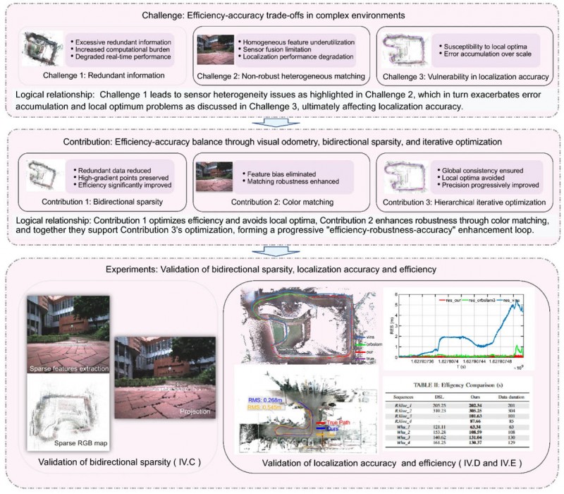
Existing map-based methods can reduce that drift by aligning camera observations with a prebuilt global map, yet many still struggle with redundant computation, weak cross-modal matching between camera images and point clouds, and optimization errors in large-scale or repetitive scenes.
The challenge is especially important for lightweight platforms that cannot afford onboard lidar, inertial measurement unit (IMU) and heavy computing. Because of these problems, deeper research is needed on camera-only map-based localization that can stay accurate, efficient and stable in complex real-world environments.
Overview of the proposed camera-only map-based localization framework. (Credit: Satellite Navigation)
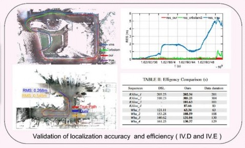
On April 20, researchers from Wuhan University and Chongqing University reported (DOI: 10.1186/s43020-026-00196-x) in Satellite Navigation a camera-only localization framework that uses prebuilt colored point cloud maps, a dual-sparsity matching strategy that retains high-gradient features in both the map and image observations, and hierarchical geometric–photometric optimization to improve both positioning accuracy and computational efficiency in GNSS-challenged environments.
The system is built around two connected stages. First, the researchers generate a sparse colored point-cloud map from a denser map produced by lidar–IMU–camera mapping, keeping only high-gradient points that preserve visually salient structures while removing weak or redundant information.
They apply a similar sparse selection process to online camera images, creating what the team calls “dual-sparsity matching” between map and observation. During localization, the method uses Lucas–Kanade optical flow to track sparse 2D image features and associates them with 3D map points, while hidden-point removal helps retain only the map points actually visible from the current viewpoint.
The pose is then refined through an iterated error-state Kalman filter in two stages: a geometric PnP-style correction for stable coarse alignment, followed by photometric refinement using image intensity consistency for sub-pixel accuracy.
Tests on the R3live and WHU-Motion datasets showed major gains over existing methods. Compared with direct sparse localization (DSL), the new approach cut absolute trajectory error (ATE) by 52% to 95% across challenging sequences, including a drop from 1.883 m to 0.152 m on R3live_5. It also improved accuracy by up to 76.6% over I2D-Loc++, reduced total processing time by as much as 47.7%, and remained robust in degenerate scenes where geometry-only localization deteriorated to 9.23 m while the proposed tracker held an ATE of 0.076 m.
Ablation results further showed that colored maps, bidirectional sparsity, and hierarchical optimization each played a distinct role in achieving the final balance of speed, robustness, and precision.
The authors said the main advance is not simply adding color to a map, but treating the global colored point cloud map as a continuous observation within the visual odometry framework. They said the framework shows that a monocular camera can localize far more robustly when paired with a prebuilt colored point cloud map and a coarse-to-fine optimization design that avoids poor local solutions.
In their view, the study offers a practical middle ground between fully sensor-rich systems and fragile vision-only pipelines, preserving much of the accuracy benefit of map-based localization without demanding equally heavy hardware on the client platform.
The work could have immediate value for indoor logistics robots, underground inspection platforms, warehouse vehicles, parking-garage navigation systems, and other low-cost autonomous agents operating where GNSS is weak or unavailable. Because the mapping can be completed offline and reused, the online platform needs only a monocular camera, which lowers sensing requirements while retaining strong global constraints.
That makes the method especially attractive for scalable deployments in structured but challenging spaces such as tunnels, campuses, hospitals, and industrial facilities. More broadly, the study suggests that future navigation systems may become both lighter and more dependable by making better use of the information already shared between maps and images, rather than relying only on ever-larger sensor stacks.