Tag: L-band

  • Converging on the jammer: Dual-satellite GPS interference localization from space

    Converging on the jammer: Dual-satellite GPS interference localization from space

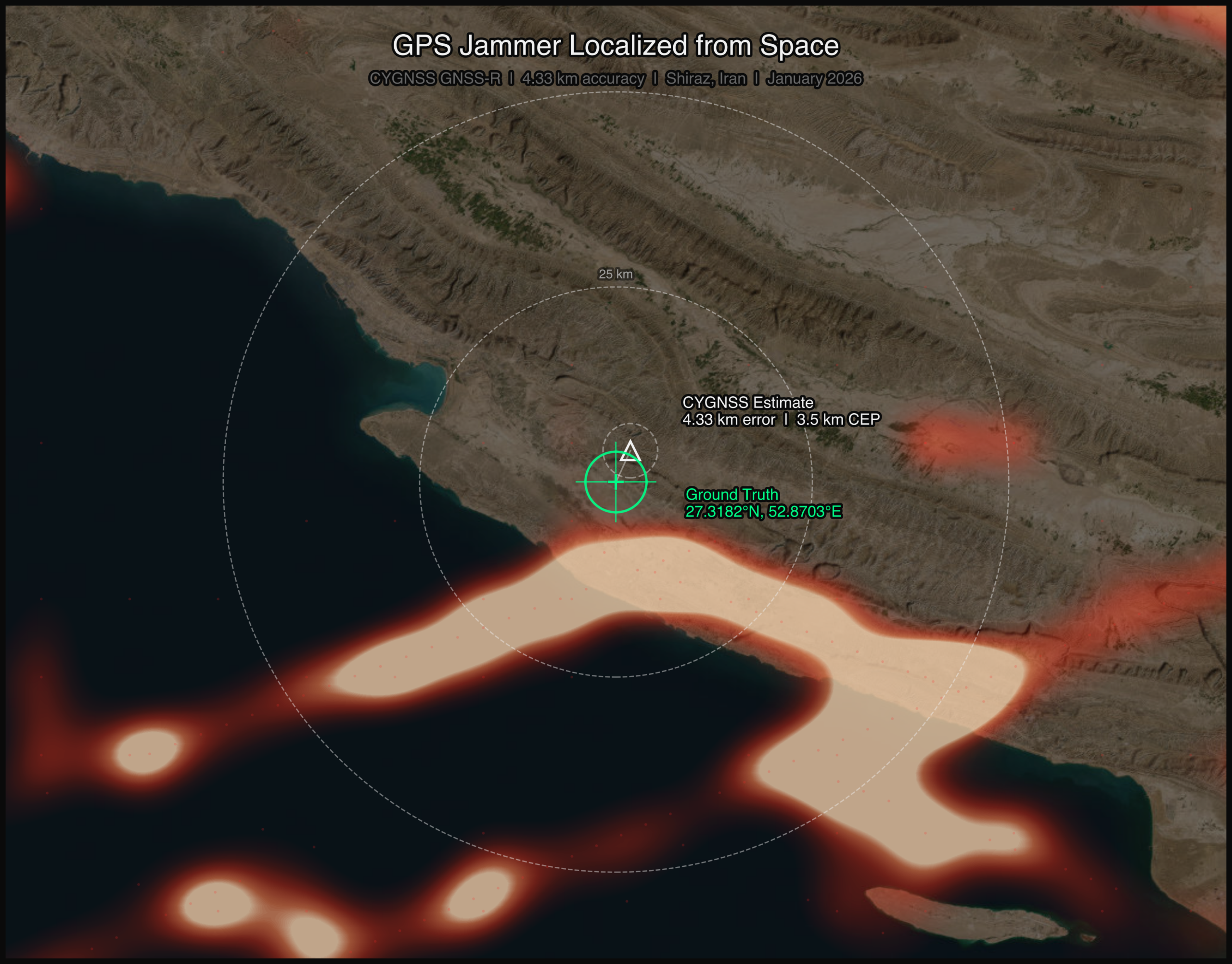
    On a January morning in 2026, a GPS jammer powered up near Shiraz, Iran. It was not the first, and it would not be the last. The Strait of Hormuz corridor has become one of the most persistently jammed airspaces on Earth. But this time, two satellites were watching from very different vantage points, and together they would demonstrate something new: that spaceborne sensors can localize a terrestrial GPS jammer to within a few kilometers, using physics alone.

    This article presents the first direct comparison of Cyclone Global Navigation Satellite System (CYGNSS) — a NASA GNSS reflectometry constellation — and NASA-ISRO Synthetic Aperture Radar (NISAR) — an L-band synthetic aperture radar for GPS jammer localization. The results challenge assumptions about which modality performs better and reveal that the answer depends on a question most analysts forget to ask.

    The setup: Known jammer, known position

    Validation requires ground truth. With help from the PNT community, we identified a GPS jammer operating near 27.32°N, 52.87°E (approximately 50 km southwest of Shiraz) that was active on Jan. 8 and Jan. 20, 2026, with confirmed quiet periods on Dec. 15 and Dec. 27, 2025. The jammer’s position was established through independent signals intelligence.

    This gave us a controlled experiment: two “jammer ON” dates and two “jammer OFF” baseline dates, with satellite coverage from both CYGNSS and NISAR spanning the full period.

    Two satellites, two physics

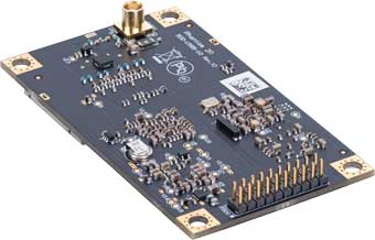
    CYGNSS is a constellation of eight microsatellites that measure GPS signals reflected off Earth’s surface. Each spacecraft carries a delay-Doppler receiver that maps reflected signal power across a grid of delay and Doppler bins, known as the delay-Doppler map, or DDM. When a terrestrial jammer is active, it floods the GPS band with noise, elevating the DDM noise floor and suppressing the coherent surface reflection. The effect is detectable hundreds of kilometers from the jammer, creating a wide-area footprint in the reflected signal data.

    FIGURE 1 Jammer localization tracks from both CYGNSS and NISAR satellite
constellations.
    FIGURE 1 Jammer localization tracks from both CYGNSS and NISAR satellite
    constellations. (All figures by Sean Gorman)

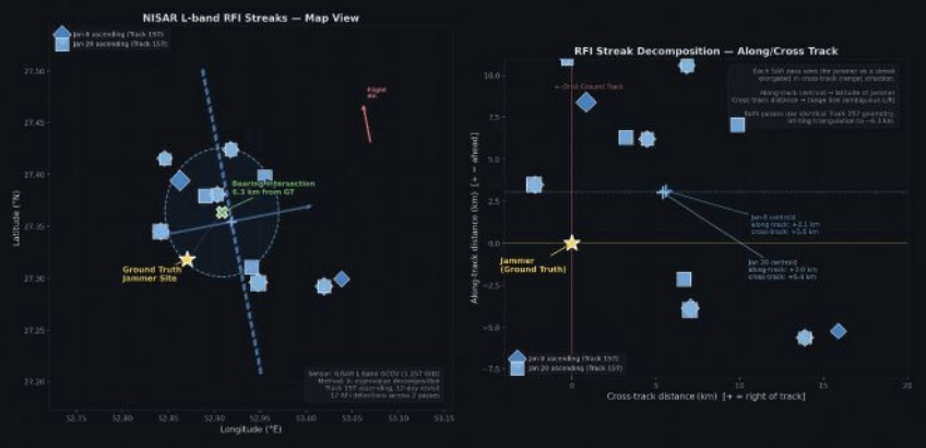
    NISAR operates an L-band SAR at 1.257 GHz, just 30 MHz from the GPS L2 frequency at 1.2276 GHz. When a GPS jammer’s broadband emissions leak into NISAR’s receive band, they create characteristic streaks in the SAR imagery. The streaks are elongated in the cross-track (range) direction, not along-track, a counterintuitive result that follows directly from SAR signal processing. In azimuth (along-track), the jammer is a fixed-point source with a valid Doppler history, so the SAR azimuth processor focuses it correctly, similar to any ground target. But in range (cross-track), the jammer’s broadband noise does not match the SAR’s chirp waveform, so range compression smears the energy across many range bins rather than compressing to a point. The result is a streak perpendicular to the flight direction, whose along-track centroid encodes the jammer’s latitude and whose cross-track extent encodes a range arc, which is the distance from the orbit ground track (FIGURE 1). The bearing of each streak encodes the jammer’s direction relative to the satellite’s ground track.

    FIGURE 2 Crosstrack visualization for NISAR RFI streaks.
    FIGURE 2 Crosstrack visualization for NISAR RFI streaks.

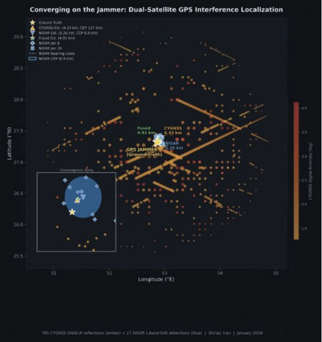
    The two sensors could hardly be more different. CYGNSS sees the jammer’s effect on reflected GPS signals, offering an indirect measurement spread across hundreds of specular reflection points. NISAR sees the jammer’s emissions directly in its own receiver, which is a more precise measurement, but only along the satellite’s narrow ground track. FIGURE 2 shows both detection sets converging on the jammer location.

    CYGNSS: 785 Detections, 4.33 km Error

    We processed all CYGNSS Level 1 data within 200 km of the jammer location on both ON and OFF dates. Four detection methods contributed observations:

    ■ DDM noise floor (419 detections): The pre-computed ddm_noise_floor variable, calibrated against the thermal noise reference, proved the strongest discriminator. Near-jammer values exceeded 15,000 counts against a ~10,000 mean background.

    ■ Spatial noise grid (299):A 10 km gridded analysis identified cells with anomalously elevated noise relative to adjacent cells.

    ■ SNR hole detection (66): Coherent surface reflections were suppressed near the jammer, creating spatial “holes” in the SNR field.

    ■ NBRCS drop (1): Surface reflectivity dropped approximately 16% near the jammer, though this method produced few threshold exceedances.

    Across four DDM channels per spacecraft and multiple passes, this yielded 785 total anomalous observations on the jammer-ON dates.

    FIGURE 3 Scatterplot of interference insensity versus distance for CYGNSS.
    FIGURE 3 Scatterplot of interference insensity versus distance for CYGNSS.

    Localizing using a simple centroid of all 785 detection positions placed the jammer 32.1 km from truth, with too many distant, low-SNR detections diluting the estimate.

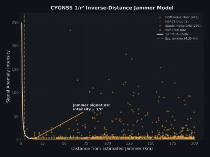
    Instead, we fit a parametric 1/r² inverse-distance model:

    I(r)=Ar2

    where A is a free amplitude parameter and r is the distance from a candidate jammer position. We jointly optimized the jammer position and amplitude using SciPy’s Nelder-Mead optimizer across all 785 observations, weighted by intensity. The optimizer converged on a position 4.33 km from ground truth, providing a 27.7 km improvement over the centroid (FIGURE 3).

    The baseline: Zero false positives

    On the jammer-OFF dates (Dec. 15 and Dec. 27, 2025), the pipeline produced exactly zero detections using the same thresholds, geographic area and satellites: a completely clean result. This suggests that the 785 detections are unlikely to be sensor artifacts or geographic anomalies. They disappear when the jammer turns off.

    NISAR: 17 Detections, 6.26 km Error

    NISAR’s approach is fundamentally different. Rather than measuring hundreds of reflected signals across a wide area, it captures direct emissions in a narrow swath, but with far greater geometric precision.

    We processed NISAR L2 GCOV (geocoded covariance) products from Track 157, Frame 15 (ascending) for three dates: the Dec. 27 baseline and the Jan. 8 and Jan. 20 jammer-ON passes. The detection pipeline used eigenvalue decomposition of the polarimetric covariance matrix:

    1. λ₁ ratio thresholding: In jammer-contaminated pixels, the dominant eigenvalue λ₁ of the 2×2 [HH, HV] covariance matrix rises sharply relative to the scene mean, indicating an unpolarized additive source.
    2. Cross-polarization ratio (HV/HH): GPS jammer emissions are unpolarized, disproportionately elevating the HV channel. Anomalous HV/HH ratios flag contaminated azimuth lines.
    3. Iterative outlier trimming: Three rounds of 1.5σ clipping removed scattered false detections, leaving 17 high-confidence streak centroids.
    FIGURE 4 Error and CEP Metrics Comparison for CYGNSS and NISAR.
    FIGURE 4 Error and CEP Metrics Comparison for CYGNSS and NISAR.

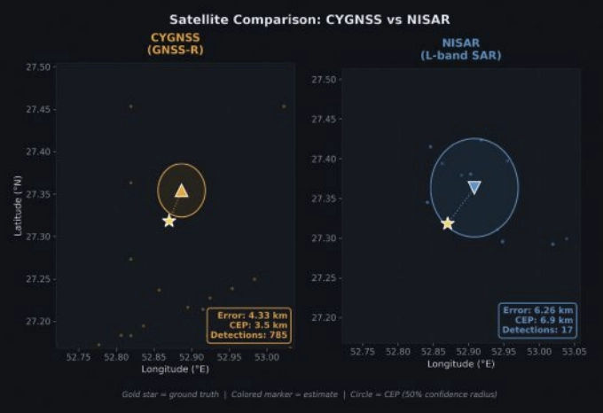
    With detections from two passes on different dates, we had two independent bearing lines. Each pass’s streak centroids defined an azimuth aligned cluster whose major axis pointed toward the jammer. A PCA fit to the two clusters extracted the bearing: 308.1° from the Jan. 8 pass and 316.2° from Jan. 20. Their intersection — computed via scipy optimization of the angular residual — landed 6.26 km from ground truth (FIGURE 4).

    The along-track/cross-track decomposition reveals why the 6.26 km error is a geometric ceiling for this dataset, not a processing limitation. Both passes come from the same Track 157 ascending orbit on a 12-day repeat cycle. The intensity-weighted along-track centroids land at +3.0 km and +3.1 km north of the jammer, a direct stable latitude measurement. The cross-track centroids land at +5.4 km and +5.6 km east of the orbit ground track, a range measurement. But because both passes share identical orbit geometry, the two range arcs are nearly parallel. The bearing difference between passes (308.1° vs 316.2°) is only 8.1°, producing a shallow intersection angle and poor cross-range resolution. A single descending pass, which would cross the ascending track at approximately 60-70°, would transform the geometry from two near-parallel lines to a genuine triangulation, potentially reducing the localization error to sub-2 km. Unfortunately, no descending NISAR pass covering this jammer site was available in the beta archive, which ends on Jan. 20, 2026.

    The CEP (circular error probable, the radius containing 50% of repeated estimates) was 6.88 km, meaning if we ran this analysis on many similar jammers, half our estimates would fall within ~7 km.

    Who wins?

    CYGNSS wins, and not just on accuracy.

    A naive confidence metric for the 1/r² fit would be the scatter of the 785 input detections (CEP = 127 km). But the detections are not the estimate; they are the inputs to a model fit. The relevant confidence question is: How stable is the fitted position?

    We answered this with a 500-iteration bootstrap: resample the 785 detections with replacement, re-run the 1/r² optimizer each time and measure the spread of the resulting position estimates. The bootstrap CEP, the median radial distance across 500 fitted positions, was 3.48 km. The optimizer converges stably to within a few kilometers of the same location regardless of which detections are included.

    This means CYGNSS achieves 4.33 km error with 3.48 km confidence, both better than NISAR’s 6.26 km error and 6.88 km confidence.

    The bootstrap CEP also reveals what the raw scatter obscures: the 1/r² fit is constrained primarily by the ~80 high-intensity detections within 30 km of the jammer. The remaining 700 distant, low-intensity detections contribute little to the position estimate — they are correctly downweighted by the intensity-weighted least squares. The fit’s stability comes from the physics: a 1/r² signal has steep gradients near the source, providing strong positional constraints where it matters most.

    Bayesian fusion: Can we get both?

    The obvious next question: Can we combine CYGNSS’s wide-area sensitivity with NISAR’s geometric precision? We implemented four fusion strategies, all designed to work without ground truth:

    ■ Bayesian Gaussian posterior: Model each sensor’s estimate as a 2D isotropic Gaussian with σ = CEP/1.1774. The posterior is the product of the two Gaussians: an analytical precision-weighted mean.

    ■ NISAR-prior constrained 1/r²: Re-run the CYGNSS optimizer with a Gaussian regularization term pulling toward the NISAR estimate, sweeping the regularization weight λ from 0.01 to 10.

    ■ NISAR-proximity re-weighted 1/r²: Apply a Gaussian kernel centered on the NISAR estimate to the CYGNSS detections before fitting, effectively upweighting observations consistent with the SAR result.

    ■ Joint CEP-balanced: Combine the CYGNSS gradient signal with NISAR cluster proximity, weighted by (σ_CYGNSS/σ_NISAR)².

    FIGURE 5 Summary statistics for jammer localization with CYGNSS, NISAR and fused approach.
    FIGURE 5 Summary statistics for jammer localization with CYGNSS, NISAR and fused approach.

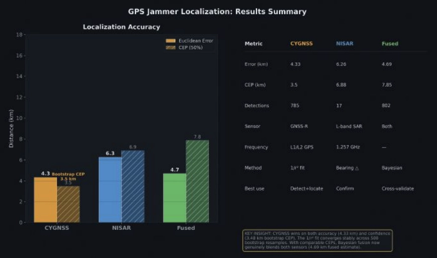
    With the bootstrap CEP, the precision ratio flips. The CYGNSS Gaussian (σ = 2.95 km) is now 2× tighter than NISAR (σ = 5.84 km). The Bayesian posterior, the precision-weighted mean, lands at 4.69 km, pulling toward CYGNSS’s better estimate while incorporating NISAR’s independent geometric constraint. FIGURE 5 shows the fusion: two comparable Gaussians whose product is tighter than either alone.

    The fused result (4.69 km error, 7.85 km CEP) is not quite as accurate as CYGNSS alone (4.33 km), because NISAR’s 6.26 km estimate pulls it slightly away from truth. But operationally, the fusion provides a cross-validated answer: two independent physics arriving at similar locations builds confidence that neither sensor is producing an artifact.

    The key insight is that the bootstrap CEP unlocked meaningful fusion. When the raw scatter CEP (127 km) was used, NISAR dominated the posterior 343:1 and fusion added nothing. With the fit-based CEP (3.48 km), both sensors contribute, and the posterior reflects genuine multi-modal evidence.

    Operational implications

    For CYGNSS: CYGNSS excels at both detection and localization. Its 785 detections across a 200 km radius, with zero false positives on baseline dates, provide unambiguous jammer detection. The 1/r² fit achieves 4.33 km accuracy with a bootstrap-verified 3.48 km CEP, meaning an analyst can trust the result to single-digit kilometer precision without ground truth. CYGNSS’s eight-satellite constellation also provides sub-daily revisit, enabling near-real-time monitoring.

    For NISAR: NISAR provides independent geometric confirmation. With just two passes over an active jammer, the bearing intersection achieved 6.26 km accuracy with a 6.88 km CEP. The 6.26 km result is constrained by orbit geometry, not by detection sensitivity. Our two ascending passes from Track 157 produced nearly parallel range arcs with only 8.1° of bearing separation. Adding a single descending pass would provide a crossing angle of 60° to 70° and could reduce localization error to sub-2 km — transforming NISAR from a confirming sensor into a precision localization tool in its own right. The limitation in this study was data availability: The NISAR beta archive contained only ascending Track 157 passes over the jammer site. NISAR’s 12-day repeat cycle and fixed ground track also mean the jammer must be active when the satellite passes overhead. NISAR’s current value is as a confirming sensor — when both modalities converge on the same location, confidence increases beyond what either achieves alone.

    For Fusion: With comparable CEPs (3.48 km vs 6.88 km), fusion now produces genuinely blended estimates. The Bayesian posterior at 4.69 km reflects real multi-sensor information. Future improvements, such as more NISAR passes with diverse bearings or CYGNSS multi-week accumulation, would tighten both estimates further.

    For the Adversary: These results demonstrate that GPS jammers operating in contested airspace are observable and localizable from orbit using openly available civilian satellite data. The 4.33 km CYGNSS result is approximately 2× better than the published state of the art for GNSS-R jammer localization (~9 km grid resolution, Chew et al., 2023) and the NISAR bearing intersection approach has not been previously demonstrated for jammer geolocation.

    Still broadcasting: Jammer persistence through conflict

    The validation analysis used January 2026 data. But on Feb. 28, armed conflict erupted in the region. Did the jammer survive?

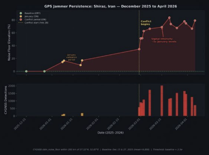
    We ran the CYGNSS noise floor detection pipeline for each day from Feb. 28 through April 6, comparing against the December 2025 baseline. The answer is unambiguous: The jammer is not only still active — it is operating at dramatically higher power.

    FIGURE 6 A timeline of jammer activity for Shiraz, Iran, from December 2025 to
April 2026.
    FIGURE 6 A timeline of jammer activity for Shiraz, Iran, from December 2025 to
    April 2026.

    In January, the jammer elevated the CYGNSS noise floor by approximately 15% above baseline. By early March, days after the conflict began, noise elevation had jumped to 50% to 60%. By mid-March, it reached 70% to 84%, where it remained through early April. Detection counts tell the same story: 89 to 192 per day in January, rising to 1,000 to 2,000 per day during the conflict (FIGURE 6).

    The escalation was immediate. On Feb. 28, noise elevation was +34.5%, already double the January level. By March 3, it had reached +62.7%, and by April 6, it peaked at +79.1%. The signal has remained at 5× the January intensity through the most recent available data (April 6, 2026).

    Several interpretations are consistent with this pattern:

    ■ Power increase: The operator increased jammer output power, perhaps in response to the conflict or as a defensive posture against GPS-guided munitions.

    ■ Additional jammers: Multiple units may have been co-located or deployed nearby, creating an aggregate signature larger than any single device.

    ■ Duty cycle change: The jammer may have shifted from intermittent to continuous operation.

    What is clear is that the jammer we localized in January was not incapacitated by the conflict. It was amplified. CYGNSS’s sub-daily revisit capability makes this kind of persistent monitoring possible using entirely passive, civilian satellite data — no tasking, no cooperation with the target state and no risk to reconnaissance assets.

    Context and prior work

    CYGNSS-based RFI detection builds on work by Chew et al., 2023, who demonstrated grid-level jammer detection at approximately 9 km resolution using DDM noise floor anomalies. Our 1/r² parametric fit extends this from detection to localization, achieving sub-5 km accuracy by exploiting the physics of signal power decay.

    At the other end of the precision spectrum, Murrian et al., 2021, demonstrated ~220 m jammer localization using ISS-mounted Doppler measurements of raw intermediate-frequency (IF) data. This approach achieves an order of magnitude better precision than our methods but requires specialized hardware and raw signal access not available on current operational satellites.

    The NISAR bearing intersection approach demonstrated here is, to our knowledge, the first published use of L-band SAR RFI streaks for jammer triangulation. The key insight is that NISAR’s proximity to GPS L2 (just 30 MHz separation) makes it an unintentional but effective GPS interference sensor.

    Summary

    Two satellites, two physics, one jammer. CYGNSS sees the interference footprint across hundreds of kilometers and localizes the source through inverse-distance physics. NISAR sees the emissions directly in its SAR receiver and triangulates through bearing intersection. Both achieve sub-7 km accuracy independently; together, they cross-validate and build the confidence that operational use demands.

    The jammer near Shiraz is still there — louder than ever. The satellites are still watching.

    Chew, C., Shah, R., Zuffada, C., et al. (2023). “Demonstrating CYGNSS as
    a Tool for Detecting GNSS Interference on a Global Scale.” IEEE Journal of
    Selected Topics in Applied Earth Observations and Remote Sensing.

    Murrian, M.J., Narula, L., Iannucci, P.A., et al. (2021). “GNSS Interference
    Monitoring from Low Earth Orbit.” Navigation: Journal of the Institute of
    Navigation, 68(1).

    NASA JPL. (2024). “NISAR L-band SAR Technical Specifications.” NASA/
    ISRO SAR Mission Documentation.
    Closas, P., Fernández-Prades, C. (2023). “GNSS Interference Detection
    and Mitigation: A Survey.” Signal Processing, 206.

  • GPS Editorial Advisory Board: Expert takes on GNSS protection

    GPS Editorial Advisory Board: Expert takes on GNSS protection

    Among the technical approaches being researched this year for GNSS/PNT protection, which do you consider most effective or promising?

    Photo: Jules McNeff
    Photo: Jules McNeff

    “The simple answer is what I have been saying many times before. The most effective way to back up GPS/GNSS is to use the terrestrial technology available from eLoran.  It is affordable, long-range, precise and essentially unjammable. However, it’s not what I would call ‘promising’ because that’s not what the government wants to hear. In fact, the government is in the process of dismantling the existing Loran infrastructure that could easily be recapitalized as autonomous eLoran stations. eLoran could provide robust nationwide timing and positioning preservation, including in the northern Pacific Ocean and Alaska, as well as across the Arctic, with Canada, to link up with our allies in the UK and Europe, who are also investing in eLoran. There is no real commercial market in the far north and there are no commercial systems proposed that can provide such coverage in those areas where we are facing challenges from Russia and China today and that will only increase into the future.”

    Jules McNeff


    Allison Brown
    Allison Brown

    L-band jamming and spoofing is now prevalent in many parts of the world. It has now been confirmed that space-based jammers have been active, as well as conventional terrestrial jamming.  Anti-jam solutions can only provide protection up to a certain jammer power level and are not a ‘silver bullet’ solution. Moreover, nulling of space-based jammers will also have the effect of nulling parts of the sky where GPS satellites are in view, degrading performance by reducing DOP. Alternative PNT solutions that are not relying on L-band signals are the most effective solution for operations in highly contested, jammed or spoofed L-band environments.”

    Allison Brown


    Photo: Mitch Narins headshot
    Mitch Narins

    “I believe that both orbital and ground-based PNT systems, operating in tandem and integrated properly, are the ultimate solution for critical infrastructure applications, but to get there, ‘the budget-office-inspired problem’ of having to pick one and only one must be abandoned: prevention is usually cheaper than curation. Only after space-based and ground-based PNT designers, developers, regulators and users understand and welcome the essential nature of PNT source diversity will we actually achieve the resilient PNT capabilities that we all need.”

    Mitch Narins

  • SBG Systems now compatible with Marinestar corrections

    SBG Systems now compatible with Marinestar corrections

    Credit: SBG Systems
    Credit: SBG Systems

    The latest versions of Ekinox, Apogee, and Navsight from SBG Systems are now fully compatible with the Fugro Marinestar G4+ precise point positioning (PPP) solution.

    Fugro Marinestar G4+ is a solution that uses satellite-based augmentation to deliver centimetric positioning accuracy without depending on a local base station. This product is suitable for maritime operations where precise positioning is important.

    With this compatibility, users can now use Marinestar correction with SBG products both via L-Band or NTRIP distribution.

    The combination of high-performance correction with inertial measurements from SBG Systems enables users to achieve accuracy in attitude and position for maritime applications. This is suitable for applications such as marine construction, dredging, hydrography and more.

  • As launch looms, threat from Ligado returns

    As launch looms, threat from Ligado returns

    Matteo Luccio
    Luccio

    “The new LightSquared business plan and the new FCC rules significantly expand the terrestrial transmission increasing the potential for interference to GPS receivers,” the U.S. departments of Defense and Transportation (DOD and DOT) wrote to the Federal Communications Commission in 2011 after the FCC granted the company permission to offer broadband via its satellite and base station networks to a wide variety of mobile broadband partners. The move — heralded by supporters as hastening the advent of 4G services across the country, especially in underserved communities — sent shockwaves across the GNSS/PNT community, which opposed the plan forcefully for the threat it posed to GPS.

    Reborn in December 2015 as Ligado Networks, the company obtained the FCC’s unanimous approval in April 2020 for the use of spectrum near the L-bands used by GPS for its 5G network. It is scheduled to launch its first deployment at the end of September.

    Nearly all the federal government, including DOD and DOT, as well as most manufacturers of GNSS receivers, are very strongly opposed. On September 9, the National Academies of Science, Engineering and Medicine’s Committee to Review FCC Order 20-48 will release its independent evaluation of the issue, as mandated by the 2021 National Defense Authorization Act.

    The study, begun in May 2021, considered three issues:

    1. Which of two prevailing proposed approaches for evaluating harmful interference is most effective to mitigate the risk of harm.

    2. The potential for harmful interference from Ligado to mobile satellite services — such as Iridium.

    3. The feasibility and practicality of the remedies proposed by the FCC.

    A summary of the report can be found here.

    Welcome Penny Axelrad

    I am very pleased to announce that Prof. Penina “Penny” Axelrad has joined GPS World’s Editorial Advisory Board.
    Penny is a University of Colorado (CU) Distinguished Professor in the Ann and HJ Smead Department of Aerospace Engineering Sciences. She received her B.S. and M.S. degrees in Aeronautical and Astronautical Engineering from MIT and her Ph.D. in Aeronautics and Astronautics from Stanford University. She has been a member of the faculty at CU since 1992, serving as primary advisor for 25 Ph.D. graduates and many M.S. and undergraduate research students.

    Penny has been active in research on GPS and PNT technology and applications for aircraft, spacecraft and remote sensing, as well as estimation of satellite orbits and attitude, since 1985, co-authoring more than 60 journal papers and 130 conference papers. She has served as principal investigator or co-investigator on grants and contracts totaling $17 million. She is a Fellow of the Institute of Navigation and the American Institute of Aeronautics and Astronautics, and a member of the National Academy of Engineering. Since 2013 she has served as a member of the National Space-Based Positioning, Navigation and Timing (PNT) Advisory Board.

    I overlapped with Penny at MIT in the mid-1980s. Now, nearly 40 years later, I look forward to her contributions to this magazine.

  • Ligado approaches Canada for spectrum permission, comments sought

    Ligado approaches Canada for spectrum permission, comments sought

    News from CANSPACE Listserv

    The Canadian Positioning, Navigation and Timing Office (PNTO) is warning stakeholders that Ligado has asked the Canadian government for access to spectrum that neighbors that of GNSS services. The request has long been a major issue in the United States because of the risk of radio frequency interference for GNSS users.

    Image: da-kuk/E+/Getty Images
    Image: da-kuk/E+/Getty Images

    Innovation, Science and Economic Development’s (ISED) Spectrum Management and Telecommunications team announced on Aug. 19 a Notice of Application from Ligado Networks. The application seeks authority for providing terrestrial mobile services in the L-band (1526-1536 MHz in the MSS downlink, and 1627.5-1637.5 MHz and 1646.5-1656.5 MHz in the MSS uplink).

    In its application, Ligado Canada is requesting that ISED adopt similar operational requirements and technical rules as those of the U.S. Federal Communications Commission. The rules are spelled out in 2020 FCC order  20-48, “FCC Ligado Amendment to License Modification Applications.” The operational requirements would allow Ligado Canada to provide ancillary terrestrial mobile services over specific portions of its licensed MSS spectrum.

    Interested stakeholders can submit comments until Oct. 18 on ISED’s website. Respondents are requested to email their comments in Microsoft Word or Adobe PDF to [email protected].


    CANSPACE Listserv is a service of Canadian Space Geodesy Forum and is administered by Dr. Richard Langley.

  • Septentrio expands product portfolio for marine market

    Septentrio expands product portfolio for marine market

    The housed AsteRx-U3 Marine and the OEM board AsteRx-m3 Fg are the two new GNSS receivers for dredging, marine construction and offshore applications

    Photo: CharlieChesvick/E+/Getty Images
    Photo: CharlieChesvick/E+/Getty Images

    Septentrio, a leader in high-precision GNSS positioning solutions, has launched two new GNSS products for marine applications: AsteRx-U3 Marine and AsteRx-m3 Fg.

    Both products offer accurate positioning near shore and offshore via centimeter-level real-time kinematic (RTK) or the built-in Fugro precise point positioning (PPP) sub-decimeter subscription service, delivered either over NTRIP internet or over L-band satellite.

    Corrections delivered over L-band allow dredging, bathymetry or marine construction projects even in areas where there is no internet service. The AsteRx-U3 Marine receiver, enclosed in an IP68-rated housing, offers a unique feature of a dedicated L-band demodulator with a separate L-band RF input, which allows for the use of dedicated antennas for excellent reception of L-band signals even at high latitudes.

    “The new products are designed around our most powerful GNSS core, bringing the latest evolution in GNSS technology to the demanding marine construction and dredging markets,” said Silviu Taujan, product manager at Septentrio. “They build on the success of the field-proven AsteRx-U Marine Fg and AsteRx4-Fg, with more processing power to allow tracking of all visible satellite signals while enabling higher update rates. AsteRx-U3 Marine and AsteRx-m3 Fg are both feature-rich receivers, combining the best-in-class RTK base and rover functionality with an option of sub-decimeter PPP positioning.”

    Orders for both products can be placed immediately. Deliveries for AsteRx-m3 Fg will follow the company’s standard lead times, while deliveries for AsteRx-U3 Marine will start from July.

    Septentrio GNSS technology is resilient to RF interference, which on vessels can come from satellite uplinks such as Iridium modems or from other radio antennas. Having robust GNSS technology means accurate and uninterrupted positioning on any vessel, even in challenging marine environments. Both AsteRx-U3 Marine and AsteRx-m3 Fg receivers offer accurate heading and pitch or heading and roll orientation information with the dual GNSS antenna configuration.

  • Editorial Advisory Board Q&A: Should all GNSS follow NavIC?

    Would it be beneficial for GNSS constellations to transmit signals at higher frequencies, such as in the S-band or the C-band, following the example of the Indian NavIC?

    Jean-Marie Sleewaegen
    Jean-Marie Sleewaegen

    “The S- and C-bands refer to frequency bands centered around 2492 MHz and 5020 MHz. The main advantage compared to L-band is the reduced effect of the ionosphere. However, this comes at the expense of higher propagation losses, increased phase jitter due to the lower wavelength, and extra cost in the receiver and antenna when combined with L-band. The added value for existing GNSS systems already transmitting multiple signals in L-band is probably low. However, because they are less congested than L-band, those bands could be attractive to new space-based PNT services.”
    — Jean-Marie Sleewaegen, Septentrio


    Alison Brown
    Alison Brown

    “The main challenge with adding additional bands to GNSS constellations (other than getting frequency allocations) is that these will not be compatible with any existing GNSS chip sets or fielded antennas. The cost/benefit analysis is unlikely to be attractive for most GNSS chip vendors to develop products with this capability.”
    — Alison Brown, NAVSYS Corporation


    Ellen Hall
    Ellen Hall

    There are benefits that the higher bands can offer in GNSS, however the constellation and system must be designed to take advantage of them, which makes it very difficult for the legacy systems that were designed around L-band only to tap into any of these benefits. Higher bands have lower ionospheric distortion, which enables better single-frequency accuracy and unlocks some interesting multi-frequency capability, while shorter wavelengths can allow for smaller antennas in user equipment. However, the tropo/atmospheric distortion gets worse as well as the spreading losses. Another consideration for the higher bands is spectrum interference, as the S-band area especially is extremely busy.

    — Ellen Hall, Spirent Federal Systems

  • DOT report: L-band, UHF, LF and fiber PNT needed to protect US

    DOT report: L-band, UHF, LF and fiber PNT needed to protect US

    In a report issued on Jan. 14, the Department of Transportation (DOT) outlined the results of its GPS Backup Technology Demonstration project. As officials had previously projected, it called for a system-of-systems approach using multiple complementary technologies.

    The report called for an architecture that included signals from space in the L-band, terrestrial broadcasts in the ultra high frequency (UHF) and low frequency (LF) spectra, and a fiber backbone to synchronize and feed precise time to terrestrial transmitters.

    The demonstration project and report were mandated by Congress in legislation passed in late 2017 and funded in early 2018. Delays within the administration resulted in the project beginning in early 2019.

    Monty Johnson of OPNT demonstrates precise time transfer through 100 kilometers of spooled fiber-optic cable. (Photo: RNT Foundation)
    Monty Johnson of OPNT demonstrates precise time transfer through 100 kilometers of spooled fiber-optic cable. (Photo: RNT Foundation)

    Demonstrations

    Of 21 firms that offered to demonstrate their wares, 11 were selected. They were:

    • Echo Ridge LLC and Satelles Inc. Satellite-based PNT technologies using the S and L bands, respectively.
    • OPNT B.V. and Seven Solutions S.L. Fiber-optic time transfer using the White Rabbit Precision Time Protocol technology.
    • TRX Systems Inc. Dead reckoning technology with inertial measurement units and localized map matching supplemented with ultra-wideband beacons.
    • Hellen Systems LLC and UrsaNav. eLoran that uses LF transmissions.
    • Serco Inc. Medium frequency R-mode.
    • NextNav LLC. Metropolitan beacon system using UHF frequencies.
    • PhasorLab Inc. and Skyhook Wireless Inc. Both use Wi-Fi frequencies. Phasorlab uses a dedicated network of transmitters. Skyhook leverages existing Wi-Fi access points.

    Five of the demonstrations were conducted at Joint Base Cape Cod, with the remainder at NASA’s Langley Research Center in Virginia.

    Timing demonstrations were assessed for system:

    • coverage (service availability) within an “appropriate area” (wireless systems only)
    • accuracy and stability across an appropriate area
    • long-term accuracy and stability of time transfer to a fixed location
    • time transfer availability and accuracy to a fixed location under challenged GPS signal conditions.

    Positioning was evaluated for:

    • coverage within a defined region
    • 2D and 3D dynamic positioning service availability and accuracy
    • availability and accuracy of static positioning
    • long-term availability and accuracy of static positioning
    • long-term availability and accuracy of static positioning under challenged GPS signal conditions

    DHS work referenced

    The report also mentions an earlier set of demonstrations done by the Department of Homeland Security (DHS).

    In December 2018, DHS’s Science and Technology Directorate performed the work through the Homeland Security Systems Engineering and Development Institute. The project “demonstrated a combination of position and timing use cases for dynamic vs. static and indoor vs. outdoor applications, along with a time-transfer use case for critical infrastructure applications.” Systems from Locata Corp, NextNav, and Satelles were evaluated.

    The DoT report says that eLoran was not part of the DHS effort because of the lack of transmitters in the area. However, “DHS had previously studied eLoran performance under a Cooperative Research and Development Agreement (CRADA) with Harris Corporation and UrsaNav and had an understanding of its capabilities.”

    A report of DHS’ December 2018 work is not publicly available, though DOT says it was used to inform their efforts.

    The only publicly available information from DHS about the eLoran CRADA seems to be a 2016 press release. A presentation and other information  is available on the UrsaNav website.

    Findings

    The 437-page DOT report is filled to the brim with detailed information about the project, individual technologies, and demonstration results.

    The Executive Summary says that, in addition to the findings from the DHS December 2018 effort (which were not listed), the DOT demonstration had four key findings:

    1. All TRL-qualified vendors offered showed PNT “performance of value” and one showed value in all scenarios.
    2. Neither eLoran company succeeded in the Static Basement Timing scenario.
    3. R-mode ranging did not meet the minimum technical readiness level (TRL) of 6.
    4. Deployment effort and coverage (infrastructure per unit area) are significant cost factors.

    Addressing the needs of critical infrastructure owners and operators, the report concluded the needed “technologies are LF and UHF terrestrial and L-band satellite broadcasts for PNT functions with supporting fiber optic time services to transmitters/control segments.”

    Reactions and way forward

    Government officials and industry observers alike have welcomed the report, though it does leave some questions on the table.

    One is about other national PNT needs. The congressional tasking was to report on GPS backup technologies for critical infrastructure and national security. The Jan. 14 report focuses on critical infrastructure needs. Information on national security requirements, some of which is classified, was provided to Congress separately by DHS and the Department of Defense.

    “Economic and homeland security are sometimes considered by agencies and Congress as subsets of national security, sometimes not,” according to one analyst. “So, we don’t know if the needs of first responders, delivery services, civil government agencies, and other essential users were ever formally considered. The good news is that the combination of systems identified, if implemented and made available to all, would likely meet the needs of most.”

    Other open issues are about implementing the report’s recommendations.

    Some have been quick to point out that the demonstrations were to inform the government, not part of a procurement.

    “If this was for an acquisition, it would have been done differently,” said one government retiree.  “Rather than having vendors set up and operate the equipment, government evaluators would have been much more hands on. And they would have made every effort to do all the trials at the same location.”

    Going forward, cost will also an important factor, as mentioned in the report’s key findings. “Depending on who you want to serve and where, the costs of different technologies vary by orders of magnitude,” said one provider.

    Reaction from those involved with the demonstration project has been generally upbeat with praise for DOT’s effort and anticipation of more progress.

    Typical were comments from Ganesh Pattabiraman, CEO at NextNav, who appreciated the real-world scenarios DOT used in the project. Regarding next steps he said, “We look forward to working with Congress on implementing the report’s recommendations.”

  • Sapcorda expands GNSS augmentation service for autonomous vehicles

    Sapcorda expands GNSS augmentation service for autonomous vehicles

    Image: Sapcorda
    Image: Sapcorda

    GNSS augmentation solution targets North America and Europe with safe and precise centimeter-level accuracy performance from two geostationary satellites.

    Sapcorda Services GmbH is now testing its GNSS augmentation services for the L-band signal in North America and Europe. The testing lays the foundation for a Dec. 1 launch of what Sapcorda said will be the strongest, most reliable GNSS augmentation signal for safety-critical navigation in autonomous vehicles and machinery.

    Available in areas without GSM coverage or mobile internet signal, the new Sapcorda L-band beam solutions from two geostationary satellites provide PPP-RTK data-feed redundancy in real-time by swapping to a second data feed when internet connectivity is not available. This automated swapping significantly improves reliability for life-critical applications such as autonomous cars.

    “To use GNSS in mass-market safety-critical applications, manufacturers need GNSS augmentation services that provide correction data with safety-critical positioning,” said Botho zu Eulenburg, CEO, Sapcorda. “By expanding our SAPA services with L-band transmission, we enable a high-power correction data stream for homogeneous performance and end-to-end data security with continental coverage in the United States and Europe — thus improving accuracy, reducing convergence time, and enabling the use of lower-cost receivers and antennae.”

    The Sapcorda L-band signal will be transmitted in the open SPARTN format, a format specifically developed for IP-based and geostationary satellite distributions. It will be invaluable for safety-critical applications in automotive (such as V2X and autonomous driving, AD/ADAS) and maritime, as well as a wide variety of uses across sectors such as industrial, robotics and drones.

    The L-band satellite beam coverage will be available on December 1, 2020. Sapcorda’s safe and precise augmentation (SAPA) service will broadcast SAPA Basic and SAPA Premium correction data streams.

    These data streams feature:

    • 99.9% service availability with fast convergence and an accuracy of less than 10 cm, delivering the precision required for safety- and life-critical applications
    • Redundancy through dual data streams when internet connectivity isn’t available, ensuring uninterrupted broadcast streaming
    • Demodulation by any L-band demodulator on the market, simplifying hardware design and reducing bill of materials
    • Availability of service coverage areas in North America and Europe, allowing manufacturers to use a single GNSS augmentation services’ solution for major global regions
    • Distributed in the same open format as IP-delivery channels (SPARTN)

    Sapcorda’s SAPA services are supported by experienced engineering teams dedicated to systems integrators and enterprise business customers. The Basic and Premium SAPA services for L-band signal operation begins in both regions on Dec. 1.

  • GPS Innovation Alliance refutes 5G claims in regard to Ligado

    GPS Innovation Alliance refutes 5G claims in regard to Ligado

    Image: A-Digit/DigitalVision Vectors/Getty Images
    Image: A-Digit/DigitalVision Vectors/Getty Images

    The GPS Innovation Alliance filed an ex parte with the Federal Communications Commission (FCC) regarding its Ligado decision. This follows a letter the alliance sent to FCC Commissioner Michael O’Rielly on July 30 regarding Ligado Networks.

    The document covers a number of details regarding the Ligado Networks and the advancement of 5G.

    According to the document, former NASA Administrator Daniel Goldin claims that FCC’s approval of the proposal by Ligado Networks to repurpose satellite spectrum in the L-Band for high-power terrestrial use should be upheld because it will help advance American leadership in 5G technologies.

    “Winning the race to 5G — against China and other countries — is important, but Ligado’s proposed network is largely irrelevant to 5G,” the GPS Innovation Alliance said in response. “The availability of Ligado’s spectrum for terrestrial use will not contribute to the advancement of 5G but will instead undermine U.S. Global Positioning System receivers and devices that are foundational to wireless technology in general, including 5G.”

    In addition, the GPS Innovation Alliance’s stated in its ex party that the use of L-Band spectrum is not critical for 5G services.

    Other points mentioned in the document include that Ligado’s spectrum is not internationally harmonized, significantly diminishing its effectiveness as a 5G band, and that Ligado’s proposed network simply will not offer a 5G service. According to the GPS Innovation Alliance, Ligado merely proposes to offer limited internet of things services, primarily delivered over custom private networks to specific geographic areas for limited vehicular and utility operations. Not only is this not a 5G service offering, but similar services are already being provided by wireless service providers, the alliance added.

    Read the full document here.

  • Bad Elf GNSS receiver adopts Hemisphere Phantom module

    Bad Elf GNSS receiver adopts Hemisphere Phantom module

    Bad Elf LLC has completed transition of all Bad Elf Flex receivers to the Hemisphere GNSS Phantom OEM module.

    Photo: Bad Elf
    Photo: Bad Elf

    As one of the first partners to incorporate the Phantom, Bad Elf Flex offers significantly enhanced capabilities and further exemplifies the company’s commitment to future-ready GNSS designs.

    “We tested the Phantom OEM modules extensively, and confirmed they deliver the promised power savings and performance improvements when integrated with the Bad Elf Flex,” said Larry Fox, Bad Elf’s vice president of marketing and business development. “Hemisphere’s technology allows us to democratize GNSS through Bad Elf Flex.”

    The new Phantom modules deliver a 30% gain in battery life, superior performance and scalable access to every GNSS constellation and signal, including GPS, Galileo, GLONASS, BeiDou, QZSS, IRNSS, SBAS and Hemisphere’s Atlas L-band, Fox said.

    Photo: Hemisphere GNSS
    Photo: Hemisphere GNSS

    Bad Elf Flex is a scalable-accuracy GNSS receiver with a daily option to choose between L-band and real-time kinematic (RTK). In standard configuration, it achieves 30-60 cm accuracy in real-time for GIS use.

    Consuming a Bad Elf Flex Token unlocks a full RTK workflow for a 24-hour period to deliver 1-cm horizontal accuracy. Bad Elf Flex stores the tokens directly on the receiver, making them available for use anytime and anywhere. Customers requiring high accuracy at all times can purchase the Bad Elf Flex Extreme bundle, with RTK capabilities permanently unlocked, for a one-time upgrade fee.

    Surveyors and their crews now have a scalable-accuracy, survey-grade receiver. GIS managers can focus on flexible field choices for work crews with varying skill levels. Bad Elf Flex falls within most capital expense budgets, allowing businesses to obtain operational and financial efficiencies.

    “Bad Elf saw an opportunity to offer the GIS community a product lineup with better than 3-meter accuracy for under $3,000,” said John Cunningham, Bad Elf’s chief executive officer. “We began three years ago with our 2-meter ($300) and 1-meter ($600) mapping-grade product offerings. Our customers continued asking us to address the 50 cm, 10 cm and 1 cm requirements for their businesses. We worked hard over the past two years to build a platform, Bad Elf Flex ($3,000), that addresses these needs without breaking budgets. We have a solution that works today and provides a foundation to meet future customer requests. We love learning from our customers and look forward to continuing this conversation and extending high-accuracy GNSS for all.”

    “Hemisphere is excited that Bad Elf’s Flex series now features our latest generation GNSS receiver,” said Miles Ware, director of marketing at Hemisphere. “We believe the scalable accuracy option made possible by our high-performance Atlas L-band correction service will be a game-changer in their served markets.”

  • 4 satellites officially join Galileo constellation

    4 satellites officially join Galileo constellation

    News from the European Space Agency

    The latest four Galileo satellites have been given the green light to begin working alongside the rest of Europe’s satellite navigation fleet, giving a further boost to worldwide Galileo service quality.

    Galileo has grown to become Europe’s single largest satellite constellation, built up over 10 launches over the course of this decade. The first of seven double-satellite Soyuz launches took place in 2011, with three sets of four-satellite Ariane-5 launches during the last three years.

    The latest quartet of Galileo satellites were launched together by Ariane 5 on July 25, bringing the number of satellites in orbit to 26.

    L-band antenna at Redu. (Photo: ESA)
    L-band antenna at Redu. (Photo: ESA)

    Once safely in orbit the satellites entered their in-orbit test commissioning, overseen by a combination of facilities across Europe.

    The Launch and Early Operations Phase team of France’s CNES space agency in Toulouse worked together with the two Galileo control centres in Fucino, Italy, and Oberpfaffenhofen, Germany and ESA’s Redu centre in Belgium.

    Redu’s 20-m antenna played an important part during in-orbit testing, allowing for high-resolution monitoring of the L-band navigation signal coming from each satellite.

    The two control centres participated by testing their control of the satellites. The operations teams confirmed their fully-trained status and their readiness to manage the fleet now it has swelled to 26 satellites in total.

    Galileo's Control Centre in Fucino is used to oversee the satellites' navigation payloads and services.(Photo: ESA)
    Galileo’s Control Centre in Fucino is used to oversee the satellites’ navigation payloads and services. (Photo: ESA)

    David Sanchez-Cabezudo, ESA’s Galileo In-Orbit Testing manager commented: “All the lessons learned and experience gained in these last years through the Galileo satellite commissioning campaigns have led us to a high level of efficiency and effectiveness — not only in managing the technical aspects of the testing operations but the large number of interfaces at contractual and human levels. A complex network of teams has had to work together to make this activity work.”

    Galileo satellites orbit in three orbital planes in medium Earth orbit, 23 222 km up. The result is that at least four Galileo satellites should be visible from any point on Earth — the minimum needed to achieve a position fix.

    Galileo's Control Centre in Oberpfaffenhofen in Germany oversees the Galileo satellite platforms.(Photo: ESA)
    Galileo’s Control Centre in Oberpfaffenhofen in Germany oversees the Galileo satellite platforms. (Photo: ESA)

    Oberpfaffenhofen Control Centre
    Galileo Initial Services commenced on Dec. 15, 2016, with each new addition to the working constellation serving to enhance the stability and speed of the system.

    A further 12 Galileo satellites are currently in production by the same industrial consortium — with OHB manufacturing the satellite platforms and Surrey Satellite Technology Ltd the navigation payloads.

    The next Galileo launch is schedule for 2020, the same year that Full Operational Capability is set to start.

    The Galileo programme is funded and owned by the EU. The European Commission has the overall responsibility for the programme, managing and overseeing the implementation of all programme activities.

    ESA is entrusted with Galileo’s deployment, the design and development of the new generation of systems and the technical development of infrastructure. The definition, development and in-orbit validation phases were carried out by ESA, and co‑funded by ESA and the European Commission.

    The European Global Navigation Satellite System Agency (GSA) ensures the uptake and security of Galileo. Galileo operations and provision of services became the responsibility of the GSA in July 2017.

    Galileo's global ground segment. (Map: ESA)
    Galileo’s global ground segment. (Map: ESA)