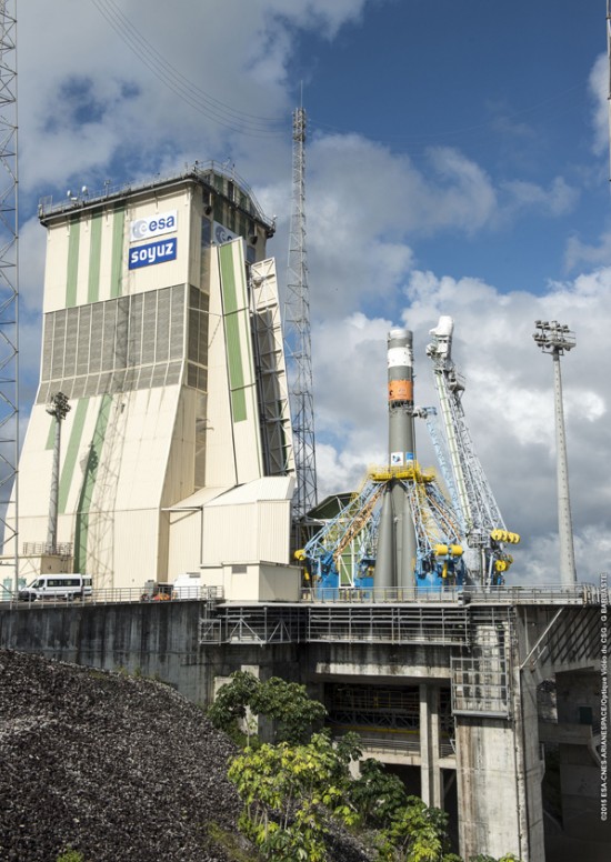
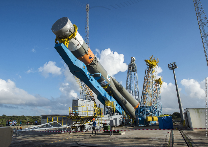
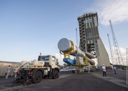
The Soyuz launcher is transferred to the launch pad. (Credit: Arianespace)
I had the honour of the first question at today’s Galileo press conference hosted by the European Space Agency (ESA), and it was about the status of the satellites launched last March. The answer to that question and others are below.
The satellites being launched this evening are destined for Plane A and will be its first occupants. They will occupy slots 5 and 8 in the plane. They will undergo a 76-day-long in-orbit test procedure before being made available to users.
The satellites launched in March, Galileo satellites 7 and 8 (a.k.a. FOC-FM3 or GSAT0203 and FOC-FM4 or GSAT0204 using PRNs 26 and 22, respectively), have essentially completed in-orbit testing and should be available to users sometime this month.
The ground segment is to be modified to enable the production of navigation messages for satellites 5 and 6 (a.k.a. FOC-FM1 or GSAT0201 and FOC-FM2 or GSAT0202 using PRNs 18 and 14, respectively) launched in August 2014 into wrong orbits (a “kind of Plane D” according to one of the ESA officials at the press conference). This will occur by the beginning of 2016 when these satellites will then be available for testing in navigation and positioning applications. They will not be included in the broadcast almanac as the orbits are too far from nominal to be represented by the standard almanac format. But the signals should be fully usable by those receivers and chipsets that can acquire and track Galileo satellites without an almanac. Testing will be carried out to see if the satellites can become part of the operational constellation.
IOV-4 (a.k.a. FM4 or GSAT0104 using PRN 20), the in-orbit validation satellite that suffered a power failure in May 2014 and is only broadcasting on the E1 frequency, may become operational for single-frequency use if suitable ground segment modifications can be made.
The next Galileo launch after this evening’s will be in December on a Soyuz launcher when another two satellites will be placed into orbit.
In 2016, there will be one launch but using, for the first time, the Ariane 5 launcher, to place four satellites into orbit.
In 2017, there will be two launches: a Soyuz launch orbiting two satellites, and an Ariane 5 launch, orbiting four satellites.
A 30-satellite constellation will be in place by 2020, following ESA’s slogan “30 satellites by 2020,” with 10 satellites per plane with each plane having two spare satellites. This should be feasible as two satellites are now being manufactured every three months. Twenty-four satellites is the minimum for Galileo operational capability.
The European GNSS Agency (GSA) has launched a new research and development funding mechanism supporting development of Galileo chipsets and receivers, intended to enable the adoption of Galileo and EGNOS-powered services across all market segments. The Fundamental Elements programme supports activities that will be carried out from 2015-2020 with a projected budget of EUR 100 million.
Fundamental Elements is part of an overall strategy of market uptake initiatives led by the GSA and in accordance with EU regulation.
“For the first time, EU regulation provides a financing tool for the market uptake of European GNSS chipsets and receivers,” said GSA Executive Director Carlo des Dorides. “The GSA will be instrumental in ensuring that the new Fundamental Elements programme contributes to the successful integration of Galileo and EGNOS.”
Fundamental Elements complements the EU’s Horizon 2020 research programme. While Horizon 2020 aims to foster adoption of Galileo and EGNOS via content and application development, Fundamental Elements projects will focus on supporting the development of innovative chipset and receiver technologies.
Fundamental Elements will provide two types of financing: grants and procurement. Grants will be provided with financing currently foreseen for up to 70 percent of the total value of the grant agreement. Intellectual property rights will stay with the beneficiary under the condition that the developed product is aimed at commercialization.
In the case of grants, the GSA publishes two annual Grant Plans, one for EGNOS and another for Galileo. These plans indicate the envisaged grants to be awarded per year. The Fundamental Elements grants are included in these plans and can be consulted before the publication of the Call for Proposals. The annual Grant Plans include a brief description of the projects and the indicative budget and timings. Procurement will be used only in cases where keeping intellectual property rights allow for the better fulfillment of the programme’s objectives.
UPDATE (9/10/15): A public workshop will be held in Washington, D.C., on Oct. 2 to provide an opportunity to discuss the draft test plan and address questions before the close of the public comment period. The workshop will be held in the RTCA NBAA/Colson Room, 1150 18th St. NW, Suite 910, Washington, D.C., 20036. Click here to register for the workshop.
The U.S. Department of Transportation today published a Federal Register Notice seeking public comment on a draft test plan for the GPS Adjacent Band Compatibility Assessment effort. The plan aims to obtain interference tolerance masks for GNSS receivers in the L1 radiofrequency band (1559-1610 MHz).
The objective of the test is to collect data to determine Interference Tolerance Masks (ITM) for categories of GPS and GNSS receivers processing signals in the 1559-1610 MHz Radionavigation Satellite Service (RNSS) frequency band, as well as receivers that process Mobile Satellite Service (MSS) signals to receive differential corrections.
Demand for commercial spectrum to support broadband wireless communications — in particular, LightSquared — has led the government to consider repurposing various radio frequencies, including the satellite communications bands next to GPS. The ITMs will be used to assess the adjacent band interference power levels that can be tolerated by GNSS receivers processing desired signals in the RNSS band.
The document outlines the requirements, the overall test plan, and the associated output data needed to successfully perform this component of the GPS Adjacent Band Compatibility assessment.
The plan can be downloaded here. Deadline for comments is Oct. 9.
In December 2012, the DOT developed its GPS Adjacent Band Compatibility Assessment Plan that identifies the processes to:
Derive adjacent-band transmitter power limit criteria for assumed new applications necessary to ensure continued operation of GPS services, and
determine similar levels for future GPS receivers utilizing modernized GPS and interoperable GNSS signals.
The DOT has previously held three public workshops to discuss the Adjacent Band Compatibility Assessment.
The new version of the precise point positioning software includes several updates and new features, including creation of GAPS Basic and Advanced user submission pages.
The GAPS Basic user submission page allows for quick and easy submission of observation files for users who frequently use GAPS’ default processing options.
The GAPS Advanced user submission page includes:
• User-selection of the orbit and clock products to be used.
• User-selection of the carrier-phase and pseudorange observables to be used.
• Optional use of GPS L2C in place of P2 for all satellites currently transmitting L2C.
• Optional use of GPS L5 in place of L2 for all satellites currently transmitting L5.
• Optional use of static-mode satellite clock interpolation (if 30s clock product is used and logging interval < 30s).
• User-selection of GDOP cut-off threshold.
• User-selection of positional convergence condition and maximum number of iterations for least-squares filter.
• Enhanced the cycle-slip detection algorithm (following Blewitt, 1990).
• A minimum of 4 satellites per epoch are required before estimation begins.
• User-selection of all available neutral atmosphere delay (NAD) prediction model and mapping function (MF) combinations.
NAD prediction models include: UNB-VMF1 (NCEP), UNB-VMF1 (CMC), VMF1 (ECMWF), UNB3m, GPT2 (1×1 deg.), ESA 2.5 and None
Mapping function options are: Vienna MF and Niell MF.
• User option to not estimate NAD.
• User option to not estimate tropospheric gradients.
• Optional use of a user-provided receiver antenna calibration file.
• NAD estimation automatically terminated if receiver rises above neutral atmosphere threshold (50,000 ft = 15,240 m).
• Added option to estimate precipitable water (if a meteorological file is submitted).
• New .ion, .cmp, .nad, and .DOP output files as well as modified formatting of the .par file.
• Improved reporting of processing parameter options and results in the HTML output.
• Added receiver clock and DOP plots.
• Added height component to kml output.
For information on the processing strategy, visit the web page. Your feedback (suggestions, bug reports, etc.) is welcome via the GAPS Development Team email: [email protected].
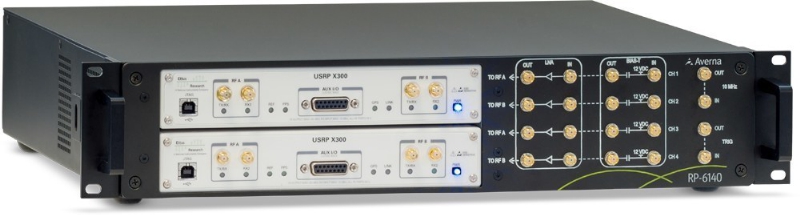
Averna and Skydel Solutions will be showcasing their latest GNSS technology simulation products at The Institute of Navigation (ION) GNSS+ conference, giving show-goers the opportunity to see the RP-6100 in action.
ION GNSS+, taking place Sept. 14-18 in Tampa, Fla., is the 28th International Technical Meeting of the Institute of Navigation’s Satellite Division and the world’s largest technical meeting and showcase of GNSS and related technology, products and services.
The companies will be presenting at Booth #100 in the Exhibit Hall, meeting attendees and discussing their latest innovations in GNSS receiver validation, among other topics. They will also be demonstrating two new GNSS solutions:
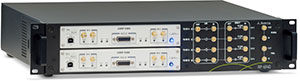
RP-6100 Multi-Channel RF Record & Playback: The RP-100 for RF application testing allows users to tecord real-world signals such as GNSS, HD Radio, LTE and Wi-Fi — plus impairments — to significantly advance projects and harden product designs.
GNSS Simulator: New from Averna’s partner Skydel Solutions, this innovative and cost-effective simulator is entirely software driven. It’s a perfect fit with the RP-6100, Averna said, enabling users to test corner cases and future events with a real-time GNSS solution.
Averna RP-6100 record and playback solution. (PRNewsFoto/Averna)
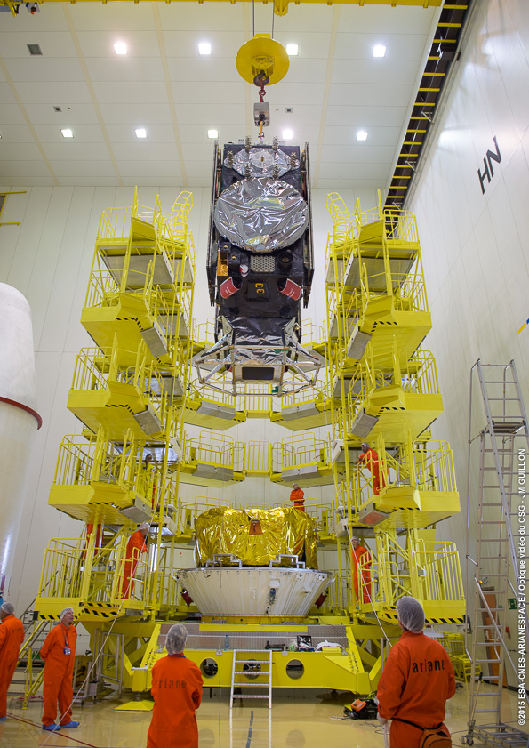
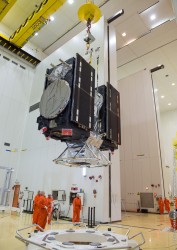
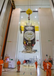
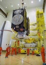
Galileos 9 and 10 are lowered onto the Fregat upper stage.
Galileo 9 and 10 are ready for launch atop a Soyuz rocket at 23:08 local time on Sept. 10 (02:08 GMT and 04:08 CEST on Sept. 11) from Europe’s Spaceport in French Guiana.
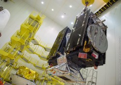
After being attached to their carrier last week, the pair of fully fueled satellites was carefully lowered onto the Fregat upper stage on Wednesday, Sept. 2, in the 3SB preparation building of the Guiana Space Centre. The following day was devoted to functional checks and inspections, preparing the Galileos plus Fregat to be encapsulated within the halves of their Soyuz rocket fairing, which took place on Sept. 4. This complete “upper composite” was then transported to the launch site and attached vertically to the first three stages of the Soyuz ST-B, the 12th Soyuz to be operated from the spaceport.
As much a spacecraft as a launcher stage, the re-ignitable Fregat will take the Galileos the bulk of the way to their designated medium-altitude orbit once the first three stages achieve low orbit, 9 minutes and 24 seconds after launch. A pair of Fregat firings will be separated by a 3-hour, 13-minute coast up to their target 23,222 km orbital altitude and 57.394° inclination.
Soyuz in Launch Zone. The basic three-stage vehicle for Arianespace’s Sept. 10 Flight VS12 rolled out from its MiK integration building in the Spaceport’s northwestern sector this morning, and was transferred horizontally to the ELS launch zone by a transporter/erector rail car.
The Soyuz rocket is moved to the launch pad and lifted into a vertical position.
The Soyuz was then erected in a vertical position and suspended over the launch pad, held in place by four large support arms. This was followed by the 53-meter-tall mobile gantry’s move-in to protect the launcher, providing a safe environment for installation of the “upper composite” containing the Galileo satellites.
Galileo 9 and 10 are the fifth and sixth Galileo FOC (full operational capability) spacecraft, and have been designated “Alba” and “Oriana” — continuing the naming process after children who won a painting competition organized by the European Commission in 2011. The satellites were built by OHB System, with Surrey Satellite Technology Ltd. supplying their navigation payloads.
The European Commission is managing and funding Galileo’s FOC phase — during which the network’s complete operational and ground infrastructure is being deployed. The European Space Agency has been delegated as the design and procurement agent on the Commission’s behalf.
Two More this Year. Two further satellites are scheduled for launch by the end of this year. One is under test at ESA’s ESTEC technical centre in Noordwijk, the Netherlands, while the other has already completed its checks and is awaiting transportation to Kourou in the second half of October. In addition, the first satellite of the following batch (Galileo 13) has arrived at ESTEC and is undergoing its thermal-vacuum test. The next will arrive by mid-September.
Follow Arianespace’s launch activity on its website.
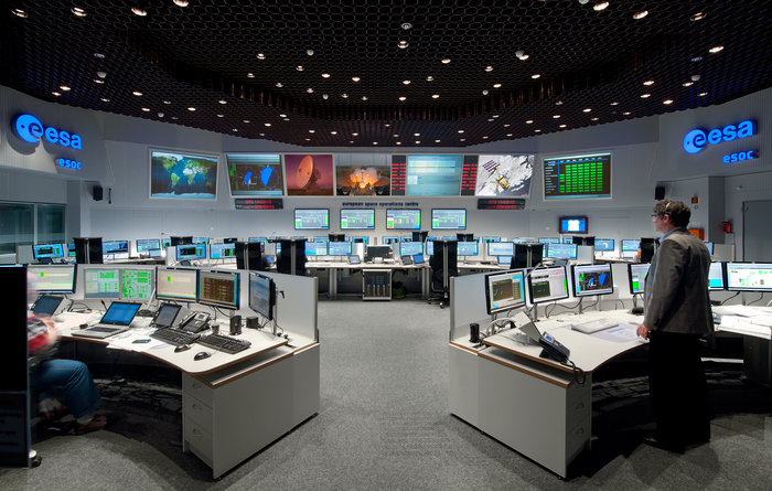
ESOC serves as the Operations Control Centre for ESA missions and hosts ESA’s Main Control Room (shown here), combined Dedicated Control Rooms for specific missions and the ESTRACK Control Centre, which manages ESA’s worldwide ground tracking stations.
Mission Control’s Mission. When the next pair of Galileo satellites is boosted into orbit on Friday, a team of mission control experts in Darmstadt, Germany, will spring into action, working around the clock to bring the duo through their critical first days in space. The fiery ascent to space will last just over nine minutes, after which the Fregat upper stage will fire twice to place the satellites into their release orbit.
Separation from Fregat, about 3 hours and 48 minutes into flight, marks the start of the critical early orbits for the team at ESA’s European Space Operation Centre in Darmstadt. Within the combined flight control team from ESA and France’s CNES space agency, each position is paired with its counterpart from the other agency and mixed “CNESOC” shifts will rotate to conduct operations around the clock. The same team conducts all the Galileo early operations alternately from ESOC and from the CNES control centre in Toulouse, France.
“Upon separation, the team will be very focused, and we’ll be watching for a number of critical events on the satellites to happen automatically at the right time and in the right order,” said ESA’s Liviu Stefanov, lead flight director for this phase. “The satellite must switch on, go into a basic flight configuration, deploy its solar wings for power, orient them towards the Sun and acquire Sun-pointing attitude. “As soon as we get communications, we’ll check its health and start sending commands to configure the satellite after completion of the automatic sequence and prepare it for the next major activity: pointing Galileo towards Earth.”
The intense activity will begin the 10-day early operations phase, during which the joint team will work 24 hours/day to oversee steps to prepare the satellites for handover to the Galileo Control Centre in Oberpfaffenhofen, for routine operations, and ESA’s Redu Centre in Belgium, for detailed payload testing.
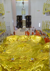
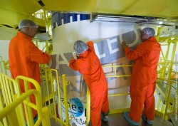
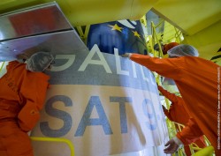
The logos of the two new satellites in the Galileo constellation are placed on the launcher fairing.
Photo Gallery
Galileos 9 and 10 are lowered onto the Fregat upper stage. (Credit: CNES/ESA)
Galileos 9 and 10 are lowered onto the Fregat upper stage.(Credit: CNES/ESA)
Galileo 9 and 10 on their dispenser being lifted towards the gold-insulation-covered Fregat upper stage. (Credit: CNES/ESA)
Galileos 9 and 10 are lowered onto the Fregat upper stage.(Credit: CNES/ESA)
Galileos 9 and 10 are lowered onto the Fregat upper stage. (Credit: CNES/ESA)
Galileos 9 and 10 are lowered onto the Fregat upper stage. (Credit: CNES/ESA)
The Soyuz launcher is transferred to the launch pad. (Credit: Arianespace)
The Soyuz rocket is moved to the launch pad and lifted into a vertical position. (Credit: Arianespace)
The Soyuz launcher is transferred to the launch pad. (Credit: Arianespace)
The logos of the two new satellites in the Galileo constellation are placed on the launcher fairing. (Credit: CNES)
The logos of the two new satellites in the Galileo constellation are placed on the launcher fairing. (Credit: CNES)
The logos of the two new satellites in the Galileo constellation are placed on the launcher fairing. (Credit: CNES)
The logos of the two new satellites in the Galileo constellation are placed on the launcher fairing. (Credit: CNES)
ESOC serves as the Operations Control Centre for ESA missions and hosts ESA’sMain Control Room (shown here), combined Dedicated Control Rooms for specificmissions and the ESTRACK Control Centre, which manages ESA’s worldwide groundtracking stations. (Credit: ESA)
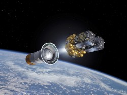
Artist’s view of Galileo satellites attached to their dispenser atop their Fregat upper stage separating from the Soyuz upper stage. The Fregat then flies them the rest of the way up to medium-Earth orbit. (Credit: ESA)
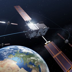
The Galileo GNSS. (artist’s rendering, courtesy ESA)
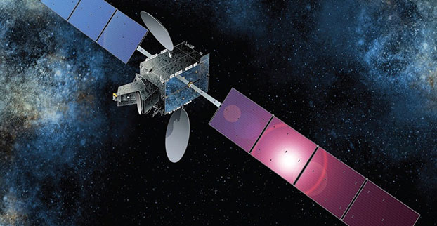
After extensive ground and space testing, the SES-5 GEO satellite has entered into the European Geostationary Navigation Overlay Service (EGNOS) operational platform, broadcasting EGNOS Signal-In-Space (SIS), according to the European GNSS Agency (GSA).
SES-5 — which replaces Inmarsat-4F2 — will ensure reliable EGNOS services until 2026. It has been introduced through EGNOS System Release V241M, which will enable a range of performance improvements. In particular, EGNOS will offer even greater stability during periods of high ionospheric activity.
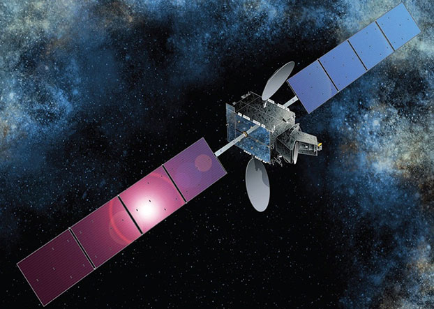
“SES-5 is the first step of the complete renewal of the EGNOS Space Segment, securing the EGNOS services for the next decade and the future transition to the dual-frequency multi-constellation services,” said Carlo des Dorides, GSA Executive Director. “It will be completed by the introduction of the ASTRA-5B signals and the procurement of a new EGNOS payload which are both planned for 2016.”
SES-5, carrying EGNOS L1 and L5 band payloads, was launched in July 2012. The integration of a second EGNOS SBAS L1/L5 band payload on SES ASTRA-5B GEO satellite is currently ongoing. The introduction of this second SES GEO satellite for EGNOS is planned at the end of 2016. SES won the contract following an open-tender procedure.
“SES is looking forward to many years of successful operation in delivering EGNOS services to the European citizens and beyond,” said Ferdinand Kayser, chief commercial officer at SES.
EGNOS is operated by the European Satellite Services Provider (ESSP), under contract by the GSA on behalf of the European Commission.
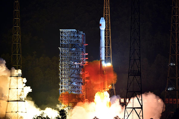
China launched two BeiDou navigation satellites into medium Earth orbit on July 25.
China launched two BeiDou navigation satellites into medium Earth orbit on July 25.
The two new satellites, BeiDou-3 M1 and BeiDou-3 M2, are in orbital slots 1 and 6 of Plane 1 (or A Plane), respectively. The satellites are designated BDS M1-S and M2-S — the “S” may stand for “Test” (in Chinese: 试验 = Shiyan).
On Aug. 14, China stated one satellite was working autonomously and had set up a link with the other satellite, successfully testing the autonomous control technology of the Beidou constellation. The inter-satellite link realizes communication and distance measurement among satellites, bringing autonomous control of the system a step closer.
Autonomous navigation is the project’s key to global operation. It enables satellites to work independently, providing users with more accurate data, according to BeiDou design engineers.
On Aug. 9, signals from the two new BeidDou satellites were received with a software-defined radio sampler operated at the European Commission’s Joint Research Centre in Ispra, Italy. The sampler is driven by orbit-prediction software that triggers a synchronized acquisition on both 1575.42 MHz and 1278.75 MHz using 1-bit complex samples at 60 megasamples per second (about 60 MHz total bandwidth). The two-line element sets for the orbits were obtained from the CelesTrak website, and predicted positions were computed using code developed following the Simplified General Perturbations Satellite Orbit Model 4 (SGP4) as documented in the U.S. Department of Defense Spacetrack Report No. 3.
To confirm the identity of the satellite being tracked using codeless tracking, we matched the measured Doppler frequency shift with the predicted one. The local oscillator clock drift was modeled using GPS L1 C/A-code signals and taken into account when matching the Doppler shift.
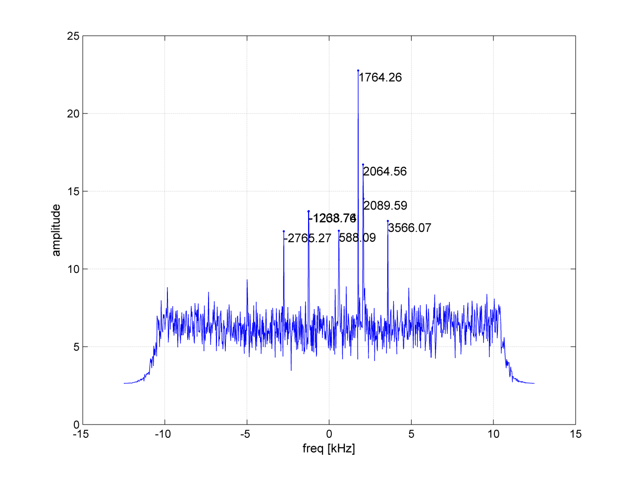
According to a presentation given at Stanford University’s 2014 PNT Symposium by Mingquan Lu and Zheng Yao from Tsinghua University, modernized BeiDou satellites broadcast an MBOC(6,1,1/11) [a multiplexing of BOC(6,1) and BOC(1,1) signals] and a BOC(14,2) signal on the L1 frequency. Neglecting the BOC(6,1) term, side lobes were brought to baseband and cross-correlated by our equipment. In Figure 1, the peak at 1756.41 MHz is BEIDOU-3 M2. This is also confirmed by cross-correlating the lobes of the BOC(14,2) signal, which is quite a unique feature of the new satellites (see Figure 2).
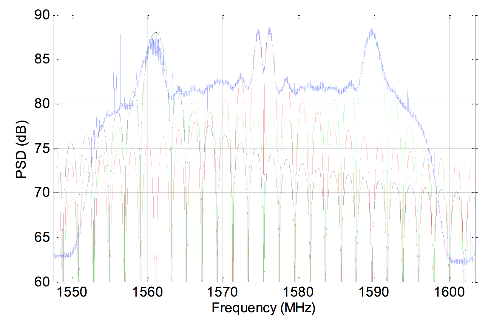
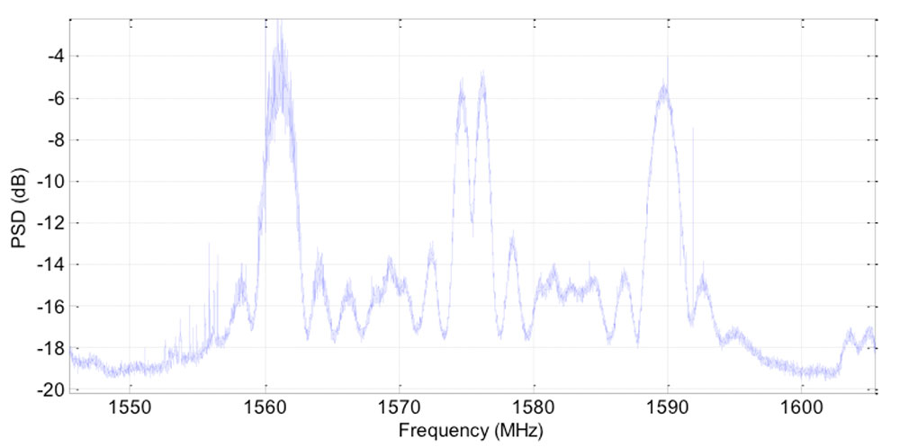
On Aug. 10, a 1.8-meter dish was pointed at the satellite, and a Tektronix RSA306 USB Real Time Spectrum Analyzer was used to sample the signal on L1 with 14-bit resolution at 112 megasamples per second. The resulting power spectrum is shown in Figure 3.
Figure 3. Power spectral density of BEIDOU-3 M2 on L1.
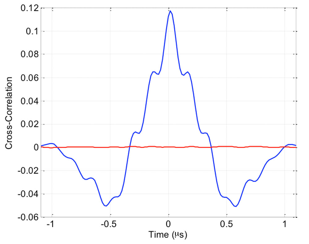
The spectrum shows very good overlap between the anticipated BOC(1,1) signal in red, BOC(14,2) in green and BPSK(2) in black. In fact, PRN33 correlates with the low side lobe suggesting that the satellite is also broadcasting a legacy signal on 1561.098 MHz (see Figure 4).
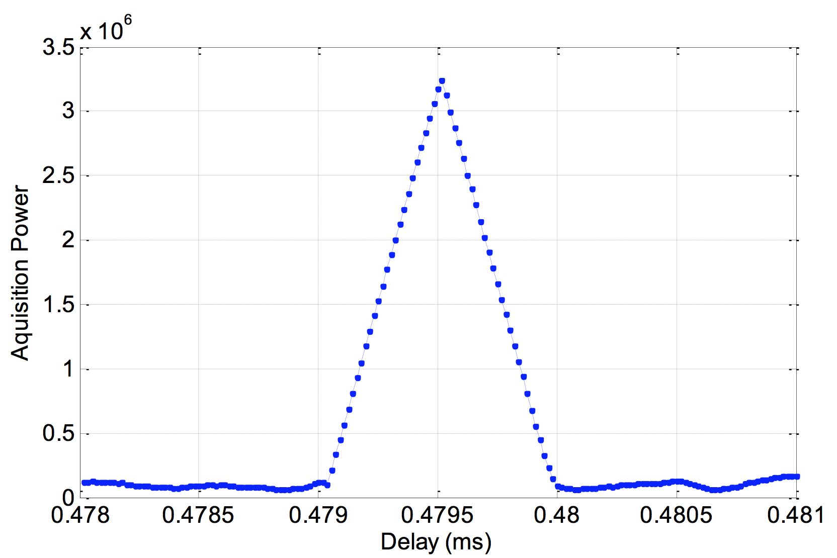
Figure 4. Cross-correlation of a BPSK(2) BeiDou code PRN33 on a 1561.098-MHz carrier.
Meanwhile, tracking by stations participating in the International GNSS Service Multi-GNSS Experiment has established that the second recently launched BeiDou Phase 3 MEO satellite is using PRN code 34, and that the first Phase 3 satellite, BeiDou I1-S launched on March 30, 2015, into an inclined geosynchronous orbit, is using PRN code 31.
UPDATED 08/28/15 with information from the European Space Agency.
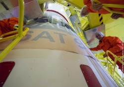
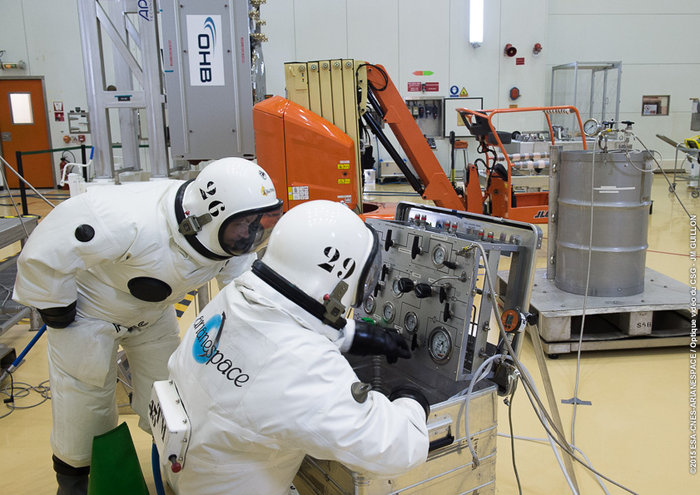
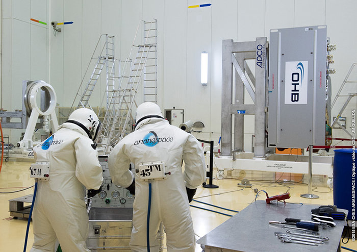
Europe’s ninth and tenth Galileo satellites were fueled Aug. 24 by technicians in protective SCAPE suits within the Guiana Space Centre’s 3SB preparation building. This left the satellites ready to be attached to their launcher upper stage in preparation for launch. (Photo:ESA)
The two European Galileo navigation satellites for Arianespace’s next mission from French Guiana have been fueled at the Spaceport, readying them for integration with their Soyuz launcher.
Galileo full operational capability (FOC) satellites 9 and 10 were “topped off” during activity this week at the Spaceport’s S3B payload preparation facility, further advancing preparations for the Sept. 10 mission — which is designated Flight VS12 in Arianespace’s launcher family numbering system, signifying the 12th liftoff of the medium-lift Soyuz vehicle from French Guiana. Lift-off is scheduled for 02:08:10 p.m. UTC.
Flight VS12’s satellites are the fifth and sixth in Galileo’s FOC phase. They were produced by OHB System, with Surrey Satellite Technology Ltd. supplying their navigation payloads that will generate precise positioning measurements and services around the world.
The Sept. 10 mission will be the fifth Soyuz flight with Galileo satellites performed by Arianespace from French Guiana — a series that began with the Russian-built launcher’s inaugural liftoff at the Spaceport in Oct. 2011.
At full deployment, the Galileo program will consist of 30 satellites — comprising operational spacecraft and reserves — situated on three circular medium Earth orbits at some 23,200 km. altitude inclined 56 degrees to the equator. The constellation — and associated ground infrastructure — will provide high-quality positioning, navigation and timing services under civilian control, and be interoperable with GPS and the Russian GLONASS.
Galileo’s FOC phase is managed and funded by the European Commission, with the European Space Agency delegated as the design and procurement agent on the commission’s behalf.
Arianespace Flight VS12 will be the company’s eighth mission this year, following the successful launches in 2015 of four heavy-lift Ariane 5s, two lightweight Vega vehicles, and one Soyuz.
Technicians donned spacesuit-like SCAPE (Self Contained Atmospheric Protective Ensemble) suits to fill each satellite with sufficient hydrazine fuel for their planned 12 years of operations in space, the European Space Agency describes in a news release. This fuel is needed for fine-tuning of their orbital paths following their launch, followed by routine orbital and attitude control over the course of their working lives.
Each Galileo satellite needs to keep its navigation antenna trained on Earth’s disc at all times, employing dedicated infrared Earth and Sun sensors for this purpose. This marked the first time Galileo had been fuelled within the Guiana Space Centre’s 3SB preparation building. Previously, the S5 fuelling building was dedicated to this purpose, but upgrades by Arianespace mean fuelling can now take place at the same location where they will subsequently be attached to their Fregat upper stage, streamlining the satellite preparation process. Completion of fuelling means the two satellites are essentially ready for launch — what needs to be accomplished now is to first attach the Galileos to their launch dispenser, then to fix this in turn to their Fregat.
The satellites plus Fregat will then be encapsulated within the launcher fairing, after which this ‘upper composite’ can then be attached to the other three stages of the Soyuz ST-B launcher. The latest Galileo launch campaign commenced at the end of July, with the arrival of the satellites in French Guiana on July 24. A “fit check” followed, to confirm the satellites as delivered in Kourou did indeed fit onto the dispenser that will first secure them in place during launch and then pyrotechnically eject them into their orbits once their target 23 222 km altitude medium-Earth orbit has been reached. This was followed by in-depth system checks and final settings of onboard navigation and data handling software parameters.
Two further Galileo satellites are still scheduled for launch by end of this year. One of these satellites is completing testing at ESA’s ESTEC technical centre in Noordwijk, the Netherlands, while the other one has already completed its testing and is awaiting transportation to Kourou in the second half of October.
In addition the first satellite of the following batch has arrived at ESTEC and is currently undergoing its thermal vacuum test. Another flight model will arrive at ESTEC by mid-September.
Let us not exaggerate — nor prematurely announce — the death of a subsystem. However, the demise of the U.S. Nationwide Differential GPS (NDGPS) network can be confidently foretold. Although a Federal Register notice dated Aug. 18 merely seeks public comment on plans to shut down a large portion of NDGPS, the handwriting is on the wall. Once having writ, the hand of fate moves on.
We should neither lament nor applaud. NDGPS, like many other technologies, has seen its time come and go, while competitors have arisen to perform its role and take its place. Such is evolution in the industrial world as well as in the biological kingdoms.
In 2016, three quarters of the currently operating NDGPS reference stations will be taken down and decommissioned. That’s not what the federal notice states, but that’s what it effectively says. The document’s comment period ends on Nov. 16. It is difficult to conceive of a public outcry that might reverse the intended course of the U.S. Coast Guard, Department of Transportation and Army Corps of Engineers.
The NDGPS network had its birth in the 1980s, as a tool to provide real-time positioning accuracy for harbor entrances and coastal navigation. Inland components were added over the years to improve river navigation, NDGPS use in precision agriculture began to grow, and a role in railroad positive train control (PTC) was much discussed. But all these efforts could not gather enough momentum to firmly establish the network’s viability. Meanwhile, satellite-based differential services from both commercial providers and the U.S. government’s own Wide Area Augmentation System (WAAS), and a network of continuously operating reference stations (CORS) from the National Geodetic Survey continually nibbled away at NDGPS’s potential customer base. Consequently, industry fielded a meager range of radiobeacon DGPS receivers.
The real death blow came in 2013, when the Federal Railroad Administration (FRA) eliminated an NDGPS requirement from its PTC program. The railroads, never a nimble industry nor one receiving the governmental support it enjoys in other countries, had by that time become the last hope of NDGPS. Ag users had already for the most part moved over to WAAS and commercial SBAS providers. Marine users did not by themselves form a sufficiently large constituency, and even they were not fully equipped nor wholesale adopters of the system.
The story of Loran bears some similarities to NDGPS, but Loran now enjoys a resurgence that NDGPS will never see. It is destined for the technological graveyard. There is an ecosystem of positioning, navigation and timing (PNT) tools and applications. Operating in a free market, with some measure of governments’ interference and manipulation, it has its own patterns of natural selection. We will continue to see the rise and fall of species. NDGPS has now been branded a dinosaur. It will be interesting to see how other technologies, competing for the same finite range of resources, will interact, thrive, or decline.
Editor’s Note: The article below has been greatly revised and expanded from the original version published Aug. 10.
By Michele Bavaro, James Curran and Joaquim Fortuny
On July 25, 2015, China launched two modernized BeiDou satellites. Although the nomenclature is still uncertain, the Joint Space Operations Centre / North American Aerospace Defense Command identifiers for the satellites are BEIDOU-3 M1 and BEIDOU-3 M2. The satellites have been placed in medium Earth orbit (MEO) and both satellites have reached their designated orbital slots.
On Aug. 9, some signals from these satellites were received with a software-defined radio sampler operated at the European Commission’s Joint Research Centre in Ispra, Italy. The sampler was driven by orbit-prediction software that triggers a synchronized acquisition on both 1575.42 MHz and 1278.75 MHz using 1-bit complex samples at 60 megasamples per second (about 60 MHz total bandwidth). The two-line element sets for the orbits were obtained from the CelesTrak website and predicted positions were computed using code developed following the Simplified General Perturbations Satellite Orbit Model 4 (SGP4) as documented in the U.S. Department of Defense Spacetrack Report No.3.
To confirm the identity of the satellite being tracked using codeless-tracking, the measured Doppler frequency shift measured by the codeless-tracking receiver was compared with the Doppler predicted using the SGP4. The local oscillator clock drift was modeled using GPS L1 C/A-code signals and taken into account when matching the Doppler shift.
According to a presentation given at Stanford University’s 2014 PNT Symposium by Mingquan Lu and Zheng Yao from Tsinghua University, modernized BeiDou satellites are expected to broadcast an MBOC(6,1,1/11) signal, being a multiplexing of BOC(6,1) and BOC(1,1) signals, and a BOC(14,2) signal on the L1 frequency. Neglecting the BOC(6,1) component, the two BPSK(1) lobes of the BOC signal were brought to baseband and cross-correlated by our equipment, in an effort to detect the presence of the broadcast signals. In Figure 1, the peak at 1756.41 kHz is believed to correspond to the MBOC(6,1,1/11) signal broadcast by the BEIDOU-3 M2 satellite.
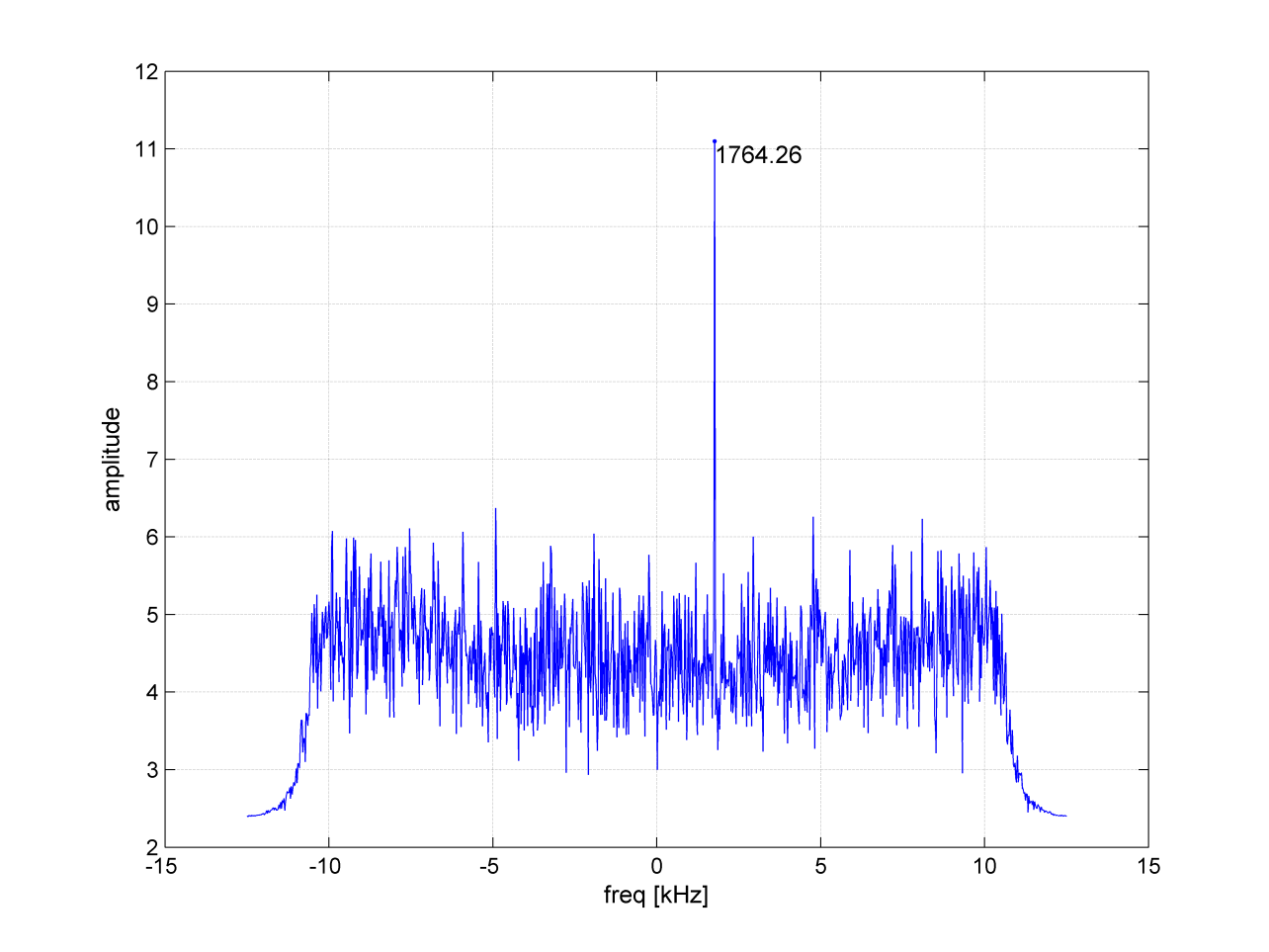
Figure 1. BOC(1,1) cross-correlation.Figure 2: Power spectral density of BeiDou-3 M2 on L1. Signal collected using a 1.8m steerable dish.
On Aug. 10, a 1.8-meter dish was pointed at the satellite and a number of further datasets were collected. The power spectrum estimated from one of these datasets is shown in Figure 2. Upon first inspection, the spectrum shows very good agreement with the anticipated MBOC(6,1,1/11) signal, centred at 1575.42 MHz. Further testing revealed that the BeiDou pseudorandom noise code (PRN33) correlates with the low side lobe, indicating that the satellite is broadcasting a legacy B1I signal on 1561.098 MHz. A replica of the B1I PRN code was generated and correlated against the received signal, to confirm the presence of the legacy BPSK(2) signal. A trace of the cross-correlation function is shown in Figure 3.
Figure 3. Cross-correlation of a BPSK(2) BeiDou code PRN33 on a 1561.098-MHz carrier.
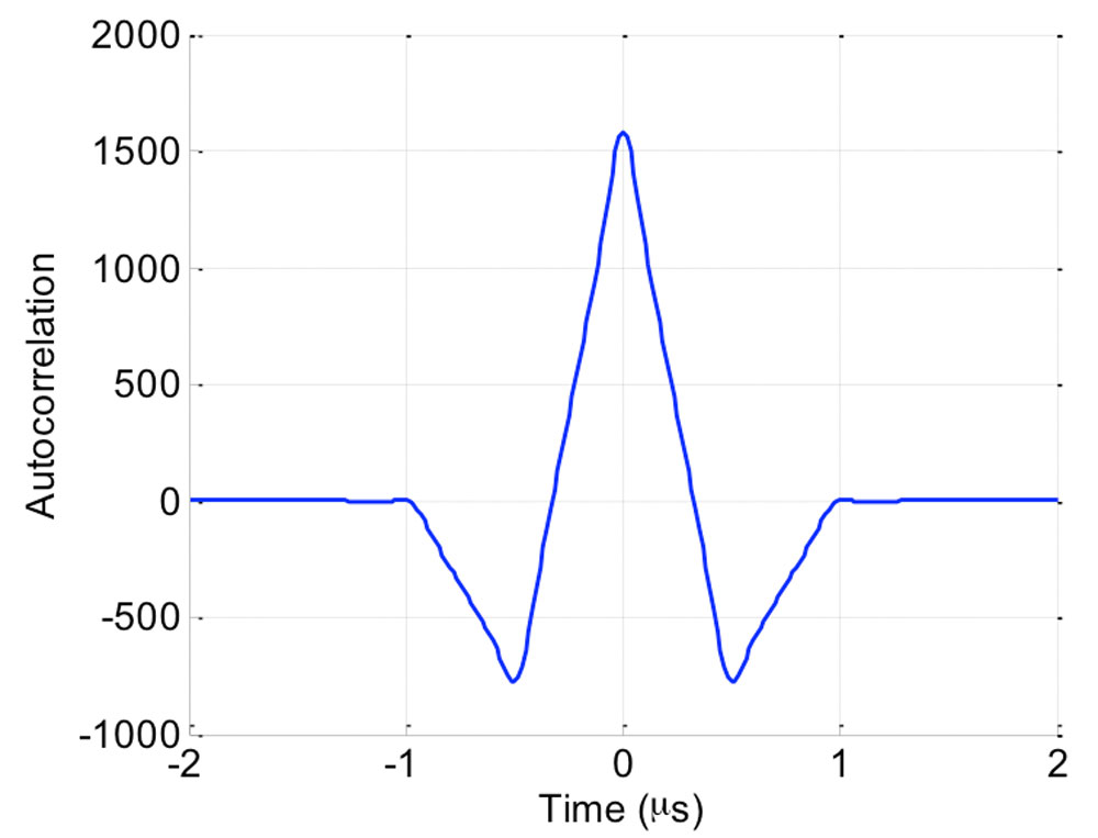
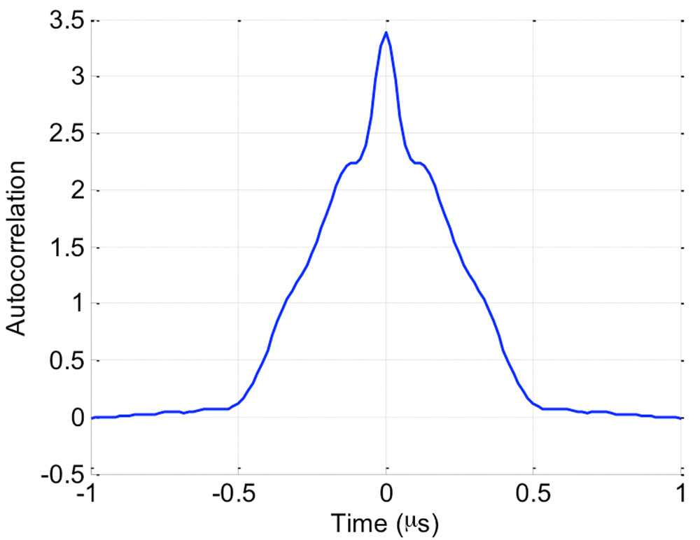
Further examining the IF data, we were able to determine the exact modulation of the central MBOC -ike signal. The raw IQ samples corresponding to the center of the L1 band were filtered to approximately 10 MHz, keeping only the MBOC signal, and tracked using a phase-locked loop operating directly at the 60 MHz sample rate, to recover the phase of the signal, prior to correlation. These phase-coherent samples were examined to gain some insight into the modulation. A simple autocorrelation of these phase-coherent samples suggested that there was no power in the quadrature channel, but that the in-phase channel contained what appeared to be an MBOC signal. More interestingly was the observation that the autocorrelation was periodic with a period of 10 milliseconds, suggesting the presence of a 10,230-chip primary code. An example of the autocorrelation of these phase-coherent samples is shown in Figure 4.
Figure 4: Autocorrelation of the TMBOC(6,1,4/33) pilot signal centred at 1575.42 MHz.
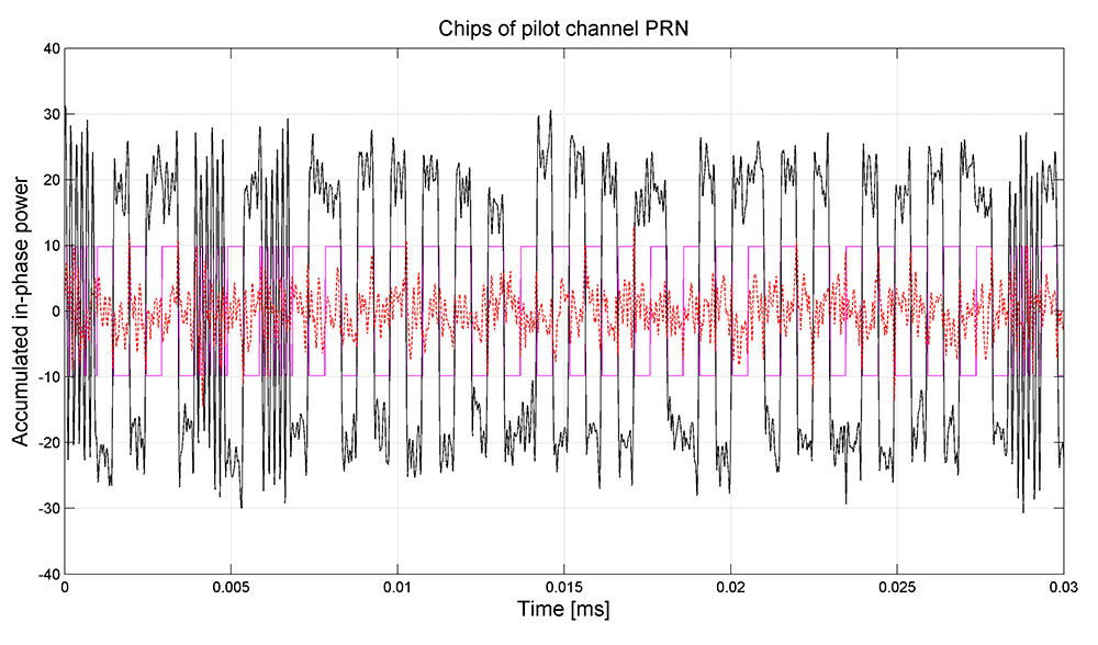
As the signal appeared to have a repetition period of 10 milliseconds, it was possible to perform a coherent combination of many successive 10-millisecond periods to achieve a sufficiently high signal-to-noise ratio to examine the modulation in detail. This process revealed what appears to be a TMBOC(6,1,4/33) modulation. Interestingly, once we aligned the samples to a 20-millisecond system time boundary via tracking of the legacy signal, the allocation of the BOC(6,1) component and the BOC(1,1) component could be identified. This pattern appears to be identical to that of L1C signal, being four segments of one-chip duration in each successive group of 33 chips. Specifically, chips {1,5,7 and 30} are allocated a BOC(6,1) pulse, and the remainder of the 33 chips are allocated BOC(1,1) pulses, as shown in Figure 5. Having produced a replica for the BOC(1,1) and BOC(6,1) components, we were able to implement a matched filter to extract the spreading sequences.
Figure 5: TMBOC(6,1,4/33) modulation visible on the received signal. In magenta, the expected chip allocation of the time-division MBOC.
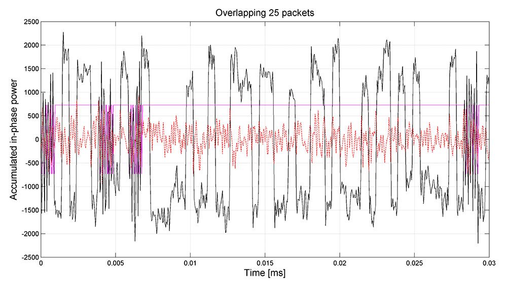
Further analysis revealed that the pilot signal was modulated by an overlay sequence, having a repetition period of 18 seconds, again, similar to that of the L1C specification. Leveraging the alignment to the 6 seconds boundary of the legacy signal, the overlay code, having a length of 1800 symbols, was extracted. The code has been circularly rotated to match with the 18-second boundary of the legacy SOW (Seconds Of Week). Note, however, that while the relative values of the primary and secondary code are likely correct, there still exists a single uncertainty as to the overall sign of the two codes. The correct codes may indeed be the inverse of what was extracted.
The assumption that a power sharing favoring the pilot over the data as suggested by Lu and Yao was confirmed by the fact that the demodulated chips do not obviously appear as a three-level signal (as one would expect, for example, with Galileo E1B-E1C). Rather, the amplitude of the received signal was dominated by the pilot signal.
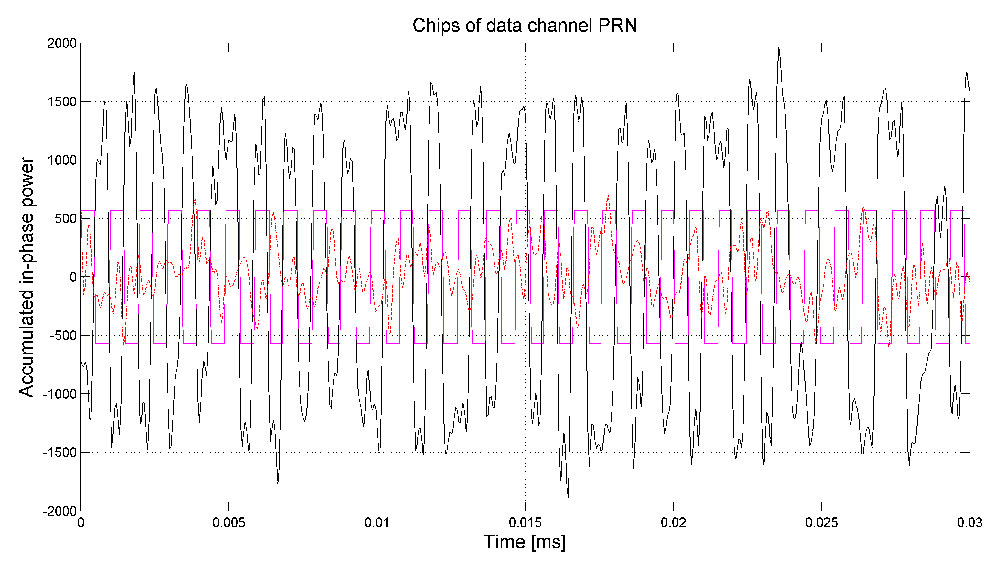
Figure 6: Autocorrelation of the BOC(1,1) data signal centred at 1575.42 MHz.Figure 7: Coherent accumulation of modernised BeiDou OS data channel (pilot stripped with SIC) over 0.5 seconds. In magenta the expected subcarrier pattern is shown.
Having extracted the pilot code, we could perform successive interference cancellation (SIC) and strip its power contribution from the signal. An attenuation of 10 dB was sufficient to bring the spreading code of the data channel to the surface, which was readily achieved, even when using low-resolution samples. After we extracted the phase of the pilot signal, the samples were aligned to be phase coherent and the autocorrelation was examined. This appeared as a BOC(1,1) signal with a period of 10 milliseconds and aligned in phase with the pilot signal. The autocorrelation is shown in Figure 6. Using again the technique described above, the individual chips were examined, as shown in Figure 7, where it is clear that the TMBOC modulation is used only on the pilot signal, and that the data signals is, indeed, a simple BOC signal. Again, a PRN sequence of length 10,230 chips was extracted.
Knowing the PRN code for the data it was also possible to demodulate the navigation symbols, which do not show any particular repetition period, suggesting a weak or no preamble, similar to the approach taken by the GPS L1C design. Given both PRN code sequences, it was possible to track the signals and estimate the actual power-sharing ratio. Initial measurements suggest that there is a ratio of 2:1 favouring the TMBOC pilot signal.
A further effort was made to identify the modulation of the two lobes, spaced at ±14 MHz relative to the center frequency. Suggestions in the literature, had indicated that these were upper and lower lobes of a BOC(14,2) signal. Initial study, however, indicates that this may not be the entire picture.
Firstly, the upper lobe, centred at 1589.742 MHz, was examined. Placing a tight filter around the main lobe and examining the chips showed a number of interesting features. Firstly, it appears to be a simple BPSK(2) signal, having a 20,460 chip code, with a 10-millisecond repetition period. It also seems to be modulated by a secondary code. The secondary code is of 20-millisecond duration, with each symbol having a duration of 1 millisecond. Interestingly, this code was found to be the same Newman-Hoffman code used on the legacy B1I signal at 1561.098 MHz, and is given by:
00000100110101001110.
A peculiar feature of this signal is the appearance of a data modulation, having a symbol period of 10 milliseconds. In all, it appeared as though the signal has a primary code with a chip-rate of 2.046 megachips per second and a period of 10 milliseconds; a secondary code with a symbol period of 1 milliseconds, repeating every 20 milliseconds, and a further data modulation with a symbol period of 10 milliseconds.
When examining the received chips more closely, a number of gaps in the signal power were observed, corresponding to the same pattern as was observed on the pilot signal at L1. This suggested that it might also be a time-division signal, but that the narrow filtering that had been applied had rejected the second component.
Figure 8: Coherent accumulation of the time-division BPSK(2) and BOC(6,2) signal located at L1 + 14 MHz over 0.5 seconds. In magenta the expected time-division pattern between chips of the BPSK and the BOC components is shown.
To identify if there was another signal broadcast during these outages, we made a search for any signal in the vicinity that followed the same modulation of secondary and data symbols as the main BPSK(2) lobe. A BOC(6,2) component was found, with lobes spaced at 6 MHz on either side of the main BPSK lobe. Specifically, they were located at 1583.604 MHz and at 1595.88 MHz, representing a BOC(6,2) component for the BPSK(2) signal at 1589.742 MHz. Once this second signal component was identified, the received samples were re-processed with a wider bandwidth, such that the entire signal could be examined. A trace of the chips is presented in Figure 8.
Indeed, this seemed a very unique signal: being centred at 1589.742 MHz, being a time-division of a BPSK(2) signal and a BOC(6,2) signal, with a time-sharing of 8/66 and a pattern given by: {1, 2, 9, 10, 13, 14, 59, 60}. Having identified the signal period as 20 milliseconds, including the secondary code, we phase-aligned the received samples and measured their autocorrelation, as shown in Figure 9.
Figure 9: Autocorrelation of the time-division BPSK(2) and BOC(6,2) signal centred at 1589.742 MHz.
Although the work had identified three signals: the TMBOC pilot signal at L1; the BOC data signal at L1; the time-division BPSK and BOC signal at L1+14 MHz, and had confirmed the presence of the legacy B1I signal at L1-14 MHz, the question of the presence of the reported BOC(14,2) signal at L1 remained. Early experiments, showing the characteristic BPSK(2) cross-correlation between the signals at ±14 MHz had suggested its presence. A lack of periodicity in this cross-correlation had further suggested that it may have a non-repeating spreading sequence. However, as yet, no conclusive evidence of its presence has been found.
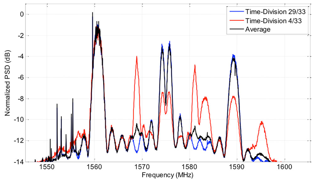
To further investigate the presence of the BOC(14,2) signal, the spectrum of the received signal was again examined. As it had been identified that there was a time-division modulation on both the TMBOC signal at L1, and on the BPSK(2)-BOC(6,2) signal L1 + 14 MHz, which used the same time-division pattern, a spectrum of the two different portions of time was estimated. The instantaneous power broadcast during each of these two periods is shown in Figure 10. This instantaneous power spectral density (PSD) represents the power broadcast at any instant by the satellite, and will be either one or other of the PSD shown, dictated by the time-division pattern (periods 1, 5, 7 and 30 out of every 33 periods). The average power of each spectrum will be, of course, scaled by 4/33 and 29/33, respectively. Note also that the relative power is distorted across frequency by the gain of the antenna element. In particular, the higher frequencies, above 1600 MHz, are attenuated by approximately 3 dB or more.
This confirmed a number of previous observations. Firstly, it was confirmed that the L1 signal contained a TMBOC signal, and a BOC signal having half of the power, as indicated by the 29/33 curve having twice the power of that of the 4/33 curve in the two BOC lobes at L1. Secondly, it confirmed the presence of the BOC(6,1) at L1 and of the BOC(6,2) at L1 + 14 MHz. Finally, it was noted that the two BPSK(2) lobes, at ±14 MHz both contain a non-time-division component. In the case of the -14 MHz lobe, there is no time division, as the power is constant for both the 4/33 and 29/33 periods. In the case of the 14 MHz lobe, it is clear that half of the power is time-multiplexed, as there is a 3 dB difference between the 29/33 and 4/33 periods. This indicates that there is a continuous BPSK(2) signal broadcast at +14 MHz. What is more, comparing the spectrum to that of the line-spectrum observed on the -14 MHz lobe, it is likely modulated with a very long, or non-repeating, spreading sequence. One explanation for this is the presence of a BOC(14,2) signal having a non-periodic spreading sequence.
Figure 10: The normalized Time-Division PSD measurement of the received signal, illustrating the instantaneous power broadcast during the 29/33 portion and the 4/33 portions.
An identical analysis of the second satellite, BEIDOU-3 M1, was conducted to determine whether or not the signal specifications of both satellites were similar. Indeed, they were found to be identical, again having a TMBOC and BOC data-pilot pair centered at L1, a Time-Division BPSK-BOC signal centered at L1+14 MHz and a legacy B1I signal at L1-14 MHz. Once again, there also appears to be a BOC(14,2) transmitting a non-repeating spreading sequence.
It appears, therefore, that the new BeiDou signal baseline will consist of a TMBOC civil signal at L1, containing a data TMBOC(6,1,4/33) pilot signal and a BOC(1,1) data signal very similar to that of the GPS L1C. This signal is complimented with a pair of open signals: one being the legacy B1I signal, located at L1 minus 14 MHz; and the second being a Time-Division of a BPSK(2) and a BOC(6,1). Beneath these two signals there also appears to be a BOC(14,2) signal having a non-repeating spreading sequence. This signal scheme is consistent between the two new satellites, BEIDOU-3 M1 and M2.
The authors invite any interested parties to contact them for more information.
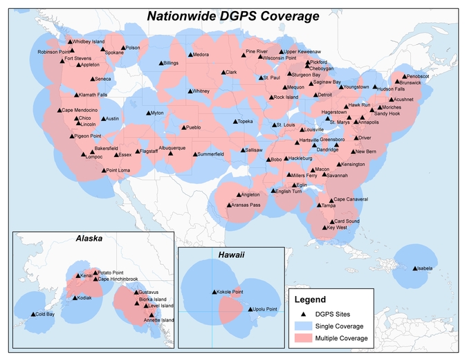
Twenty-two NDGPS sites that serve coastal areas would remain operational under the proposal.
An Aug. 18 Federal Register notice proposes shutting down the Nationwide Differential Global Positioning System (NDGPS) in January 2016 because of a decline in its use, except for sites in coastal areas.
The notice, issued by the U.S. Coast Guard (USCG), Transportation Department (DOT) and Corps of Engineers (USACE), reads:
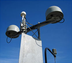
The Nationwide Differential Global Positioning System (NDGPS) service augments GPS by providing increased accuracy and integrity using land-based reference stations to transmit correction messages over radiobeacon frequencies. The service was implemented through agreements between multiple federal agencies including the USCG, DOT, and Army Corps of Engineers, as well as several states and scientific organizations, all cooperating to provide the combined national DGPS utility.
However, a number of factors have contributed to declining use of NDGPS and, based on an assessment by the Department of Homeland Security, DOT and USACE. DHS, DOT and USACE are proposing to shut down and decommission 62 DGPS sites, which will leave 22 operational sites available to users in coastal areas.
A DGPS reference station antenna.
Contributing factors cited in the decision are:
USCG changes in policy to allow aids to navigation (ATON) to be positioned with a GPS receiver using Receiver Autonomous Integrity Monitoring (RAIM), which assesses the integrity of a GPS signal within the receiver;
increased use of Wide Area Augmentation System (WAAS) in commercial maritime applications, which uses ground-based reference stations and satellite communications to improve accuracy;
limited availability of consumer-grade NDGPS receivers;
no NDGPS mandatory carriage requirement on any vessel within U.S. territorial waters;
the DOT Federal Railroad Administration’s determination that NDGPS is not a requirement for the successful implementation of Positive Train Control (PTC), which provides the railway system the capability to positively enforce movement authorities along railroad systems.
In April 2013, announced that DHS and DOT were in the process of analyzing the need for NDGPS. “The response to the 2013 notice was limited, but the responses received were well informed on the NDGPS system, its use, and current and potential applications,” the notice reads. “While a limited number of responders found the broadcast of corrections to be beneficial, no respondents reported the discontinuance of DGPS broadcast to be detrimental or harmful. Ship pilots in particular noted that DGPS can be critical in confined waterways for precise ship-handling maneuvers.”
Public comments on the proposed shutdown and decommissioning of 62 DGPS sites are being accepted until Nov. 16. Termination of the NDGPS broadcast at these sites is planned to occur on Jan. 15, 2016.
Full details on how to submit public comments can be found on the Federal Register page.