GeoOptics, a satellite-based environmental data services company, in cooperation with Atmospheric and Environmental Research (AER), an environmental research and development company, has announced the initial results of an Observing System Simulation Experiment (OSSE) showing the reliability of radio occultation data in improving predictions of severe weather and flash flood events.
Using weather prediction models and data assimilation techniques, AER evaluated the potential benefit of observing Earth’s atmosphere with a vast future constellation of many hundreds of orbiting GNSS – Radio Occultation (GNSS-RO) receivers. As a case study, the model used the convective system that brought severe weather to Oklahoma in 2013, which included an Enhanced Fujita Scale-3 tornado and heavy rains.
“The improved characterization of moisture in the lowest 4-5 km of the atmosphere is very significant and, working with our colleagues at AER, we believe quite a rigorous scientific conclusion,” said Conrad Lautenbacher, GeoOptics CEO. “We see commercial provision of GNSS-RO as a valuable complement to public sector systems and a reliable, low-cost way to achieve the levels of scale tested. We are very excited by the results.”
Through collaboration begun in 2014, the two companies set out to assess the impact of vastly increased numbers of GNSS-RO profiles on regional weather forecasting within the context of a global weather satellite system. Oklahoma was the region of focus of the study, an area with a history of severe weather phenomena. Today’s total global GNSS-RO profiles number approximately 1,800 per day, of which 0.64 profiles per day are readings taken over Oklahoma.
In the study, AER and GeoOptics modeled from 50,000 to 2,000,000 global profiles per day through the deployment of the planned CICERO satellite constellation. Such large scale would correspondingly increase the profiles per day over Oklahoma to between 17 and 700.
“We see commercial remote sensing and particularly the GNSS-RO technology as a paradigm change in developing and maintaining a cost-effective, next-generation operational observational infrastructure for environmental prediction,” said AER President Ron Isaacs. “The superb GNSS-RO technology knowledge base at GeoOptics provides an ideal and exciting complement to AER’s decades-long experience in today’s operational remote sensing and weather prediction practices, which include the current use of GNSS-RO sensing.”
GNSS-RO profiles provide measurements of atmospheric temperature, moisture, and pressure with a precision unrivaled by other space-based techniques. The RO sensor gathers this information by precisely observing perturbations imposed on ubiquitous GPS radio signals as they pass through the atmosphere. Today, nearly 3,000 organizations in more than 80 countries use RO data in Numerical Weather Prediction (NWP) and research. NOAA’s own studies show that more accurate mid- to long-term forecasts can be made up to 15 hours sooner using the data collected from the current limited set of experimental GPS-RO sensors.
GeoOptics plans to launch an array of powerful GNSS-RO sensors on its CICERO constellation of low-Earth-orbiting satellites. The rollout of the constellation will begin in the third quarter of 2015 and will deliver more than 50,000 global profiles per day when fully deployed. As demand grows, the 24-satellite CICERO constellation will be expanded to carry additional and complementary instruments, such as scatterometry and gravity sensors.
“GeoOptics will advance a small satellite observing model that starts with GPS radio occultation,” Lautenbacher added. “We believe an integrated private company like ours can deploy such systems for a fraction of current costs to the government.”
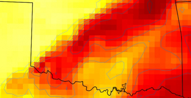
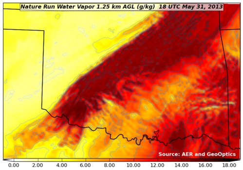
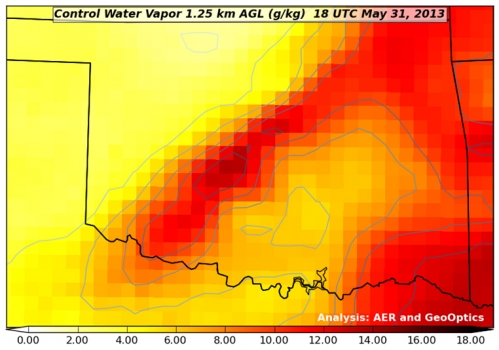
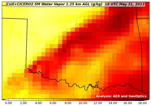
Figure 1. “Nature Run” (the truth reference) atmospheric water vapor at about 4,000 feet above the ground. The yellow-to-red color scale (bottom of figure) indicates how much water vapor is present, i.e., yellow is dry and red is moist. This realization of atmosphere moisture during an Oklahoma severe weather outbreak in May 2013 is the yardstick against which our assimilation experiments are compared for realism. It has a horizontal resolving power of about 1 1/4 mile (i.e., 2 km).Figure 2. Atmospheric water vapor analysis using conventional observing system. Valid time, vertical level and color scale are the same as in Figure 1. Note that the data fusion experiments use a bigger grid than the Nature Run (Figure 1) with a horizontal resolving power of about 11 miles (i.e., 18 km).Figure 3. Atmospheric water vapor analysis using conventional observing system + CICERO radio occultation observations. The distribution of water vapor in this analysis is much closer to the Nature Run (Fig. 1) in pattern and magnitude than the Control result (Fig. 2).
Jan. 6 was the last day of service for GPS satellite SVN-26. SVN-26 was a Boeing/Rockwell International Block II GPS satellite launched July 7, 1992. It was one of the first generation of operational GPS satellites, and had a design life of only 7.5 years. On Jan. 7, SVN-26 (PRN-26) was transferred from the operational ground control system (AEP) to Launch, Anomaly and Disposal Operations (LADO).
CGSIC Executive Secretariat Rick Hamilton, USCG Navigation Center, remarked on its longevity. “A testament to the satellite engineers and the men and women of the Air Force, the Second Space Operations Squadron at Schriever Air Force Base has successfully managed SVN-26 in its mission for over 22 years.”
In the near term, PRN-26 will be used for clock checkout activities on a few LADO satellites. The compatibility test for SVN-71, the next IIF satellite to launch (SVN-71/IIF-9), is scheduled for the week of Jan. 19. PRN-26 will be used by SVN-71 for the compatibility test, and then be used again for LADO satellite clock tests.
PRN-26 will be reassigned to SVN-71 just before launch from Cape Canaveral on March 25.
Trimble has introduced TerraFlex Advanced, an enhanced edition of its TerraFlex field data capture software, which manages asset collection and update activities for everyday geospatial requirements. Organizations across a variety of industries, including environmental management, utilities and government agencies, can deploy a common workflow for field workers to collect or inspect their assets efficiently using TerraFlex Advanced.
TerraFlex Advanced enables GIS professionals to stay productive by keeping their data and devices up-to-date and organized. It allows users to import existing assets or GIS data into their TerraFlex projects and make real-time updates to the data in the field. The information can be shared across the project organization, so all project members — from the field to office — are working with the most up-to-date data available.
In addition, a new version of the TerraFlex Mobile apps supports Trimble RTX technology-based correction services. Trimble RTX (Real Time eXtended) is a high-accuracy GNSS correction technology that delivers repeatable centimeter-level positioning worldwide to compatible GNSS receivers. GIS professionals now have more flexibility to achieve the accuracy required by their highly mobile workflows in real-time, without being tied to a base station or local VRS network.
With TerraFlex Advanced, users can collect, process and manage geospatial data quickly and efficiently across a fleet of mixed consumer and professional data collection mobile devices and platforms. Local governments who require regular data updates on city assets, utility workers performing frequent inspections on infrastructure, and many other mapping and GIS organizations can update new and existing data while in the field much faster.
“In today’s environment, asset conditions are constantly changing and access to real-time information about these assets is crucial to decision-making and sustainability of those assets,” said Alain Samaha, business area director of GIS and Software for Trimble’s Geospatial Division. “TerraFlex Advanced addresses this growing requirement by ensuring GIS field crews are equipped with current information so they can make informed decisions, avoid costly rework, and plan and schedule resources efficiently for the maintenance of assets.”
Part of the Trimble InSpherecloud-based software platform for the management of geospatial applications, data, and services, TerraFlex Advanced extends the robust project, user and form functionality in the original TerraFlex Basic edition, keeping field crews organized and productive on a variety of devices and in a wide range of environments.
In addition to TerraFlex Advanced software, Trimble also announced new enhancement to its InSphere platform applications — Equipment Manager and Data Manager.
Equipment Manager — A software application that enables geospatial enterprises to unify management of all their equipment, Equipment Manager now lets users manage custom equipment types, including non-Trimble devices, accessories, and any other equipment that needs to be managed together with their Trimble mapping and surveying equipment. Additionally, users can stay on top of required updates and keep their field equipment properly maintained with service scheduling and alerts.
Data Manager — Data Manager allows users to securely access, search, visualize and share geospatial information. This module now expands support for more data types, including all features from TBC files, image features, and TGO files, enabling users to upload more data into the application to manage, view, search and share with other project stakeholders.
Designer Timo Arnall has created lamps that change brightness depending on the strength of received GPS signals. The glowing orbs were made with Einar Sneve Martinussen and Jørn Knutsen as part of a research project at the Oslo School of Architecture and Design. The research began in 2009 with RFID and Wi-Fi projects that aim to reveal technology in a visual way.
“GPS is widely used, yet it’s invisible and few of us really have any idea of how it works or how it inhabits our everyday environments. We wanted to explore the cultural and material realities of GPS technology, and to develop new understandings about it through design,” Arnall said on his website.
Dubbed “Satellite Lamps,” each orb is embedded with a GPS receiver. As the strength of signal wavers in and out, the glowing orbs become brighter or dimmer. The stronger the signal, the brighter the lamp.
“Satellite Lamps shows that GPS is not a seamless blanket of efficient positioning technology; it is a negotiation between radio waves, earth-orbit geometry and the urban environment. GPS is a truly impressive technology, but it also has inherent seams and edges,” Arnall said.
Arnall created a timelapse video showing the lamps in action. “When we photograph them as timelapse films, we start to build a picture of how these signals behave in actual urban spaces,” he said.
The Russian government is establishing a joint stock company named “GLONASS” with 100-percent participation of the state, according to the website of the Russian Cabinet, as reported by Ria Novosti.
Russian President Vladimir Putin in July 2014 ordered the government to develop and adopt a roadmap for the creation of an open joint-stock company “GLONASS” with 100-percent state participation. According to the plan, the property complex of the state automated information system “ERA-GLONASS” will be transferred to the share capital of the newly created company. ERA stands for Emergency Response in case of Accidents. “To establish a joint-stock company ‘GLONASS’, 100 percent of the shares of which are federal property… Set the size of the share capital of the company is 100 million rubles,” said the executive order.
Deputy Prime Minister Dmitry Rogozin in September welcomed the establishment of the company, calling it a first step in the commercialization of space-based services.
The authorities intend to develop the GLONASS infrastructure to enhance the quality and quantity of services. A development strategy for the new company is due March 30.
Col. William Cooley, Director, U.S.A.F. Global Positioning Systems Directorate.
Colonel William Cooley, director of the Global Positioning Systems Directorate, has been nominated by President Obama to the Senate for appointment to the rank of brigadier general, United States Air Force, according to an announcement by Secretary of Defense Chuck Hagel. He is the first SPO director in many years to be nominated for general officer rank, according to Don Jewell, GPS World’s contributing editor for defense.
Cooley is currently serving as senior materiel leader and director, Global Positioning Systems Directorate, Air Force Space Command, Los Angeles Air Force Base, California.
“This is a great accomplishment for Bill and for the GPS community,” Jewell said. “We are all certainly very proud of him and his accomplishments and his unflagging support for the PNT community globally.”
“This nomination is an outstanding achievement as it clearly demonstrates continued senior leadership confidence in his ability to lead the men and women in our Air Force. We have been privileged to see that for ourselves here at SMC,” said Samuel A. Greaves, Lieutenant General, USAF, Commander, Space and Missile System Center.
This tri-band receiver technology, when combined with baseband search and track engines, allows true simultaneous tracking of all current L1 GNSS signals, including GPS, GLONASS, BeiDou, Galileo, Quasi-Zenith Satellite System (QZSS), and satellite-based augmentation systems (SBAS).
By Charles Norman and Andreas Warloe, Broadcom Corporation
Starting with the first commercial GPS receivers, adding support for incrementally more complex GNSS systems presents significant challenges for GNSS hardware and software developers. The latest systems, especially Galileo, were designed with the assumption that Moore’s law would provide nearly unlimited computing resources and memory over time. The expected improvements in ASIC technology have indeed occurred, but market demands have pushed the size, cost, and power consumption of GNSS chipsets down, rather than allowing capabilities to grow freely.
GNSS in cellular phones is now expected to be always-on and to add only a few dollars to the cost of a $600 smartphone. Even as customers and phone manufacturers demand GLONASS, BeiDou, and Galileo support, chipset cost is not allowed to increase significantly. Instead of, in essence, designing four separate GNSS receivers in the chip, cost and size pressures force designers to look for commonality among the signals in order to share hardware blocks and software or digital signal-processing algorithms.
GNSS L1 Signal Down-Conversion
Commercial L1 GNSS signals span a 50 MHz range. It is getting harder for a single antenna to cover the entire bandwidth, but it is possible. The radio input contains three frequency bands of interest, spanning a total of 15 MHz:
BeiDou, at 1561 MHz, is at the low end;
GPS, Galileo, satellite-based augmentation systems (SBAS), and Japan’s Quasi-Zenith Satellite System (QZSS), at 1575 MHz, are in the middle; and
GLONASS, at 1602 MHz, is at the top.
The radio process in the new tri-band receiver described here first amplifies the signal using a low-noise amplifier (LNA) to keep the system noise figure as low as possible. Then it downconverts to an intermediate frequency (IF) and filters the three bands into separate channels. The three bands are then digitized and sampled at the lowest possible sample rate. The sampled bands can be filtered digitally to remove blockers and downconverted to baseband. The baseband samples are buffered by constellations to allow parallel access for searching or tracking on each visible satellite.
All satellites in a code-division multiple access (CDMA) constellation can share baseband buffers, but the frequency-division multiple access (FDMA) constellation, GLONASS, uses a separate buffer for each satellite. This is because the memory and power required to store each satellite in use is less than storing the entire FDMA bandwidth.
Signal Similarities and Differences
All GNSS satellite signals use binary phase-shift keying (BPSK) modulation. The biphase modulation is generated from a high rate pseudorandom noise (PRN) code that is exclusive-ORedwith a low-rate data stream.
The PRN code for all constellations except Galileo is generated from linear feedback shift registers (LFSRs). Galileo’s PRN code is a memory code with a bit-offset carrier BOC(1,1)/BOC(6,1) modulation. All constellations except GLONASS are CDMA. Each satellite in a CDMA constellation is at the same frequency but has a unique PRN code. GLONASS is FDMA. Each visible GLONASS satellite has a unique frequency, but all use the same PRN code.
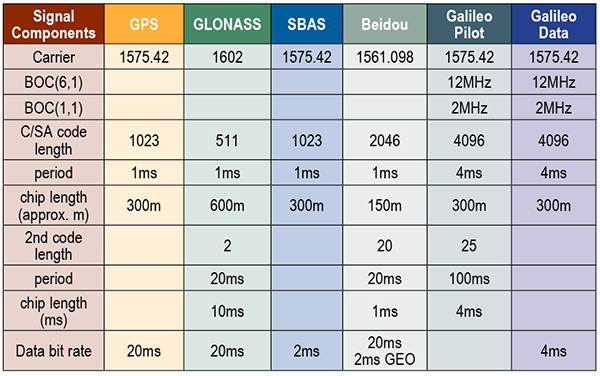
L1 GNSS constellations use four different code lengths: 511, 1023, 2046, and 4092. The code length has a large impact on the power required to detect a signal. Data modulation is different on each constellation. BeiDou data is exclusive-ORed with a secondary code. Galileo has a secondary code-only channel. The highest data or secondary code rate is 1 kHz on BeiDou, and the lowest is 50 Hz on GPS. Table 1 shows a detailed chart with the main signal parameters for all L1 GNSS signals.
Table 1. Parameters for all L1 GNSS signals.
Radio Overview
The radio processing starts with a LNA, which utilizes a 72-nanometer negative metal oxide semiconductor transistor in a cascade configuration, with deliberate capacitive feedback and inductive source degeneration to achieve an excellent noise figure (~1.5 dB system noise figure) while maintaining a good input match. Two external matching components are required to achieve an optimal input match.
Following the LNA is an in-phase/quadrature ring mixer switched-capacitor mixer. With this style of mixer, the LNA output is only connected to one mixer output at a time and, thus, the optimal noise figure is obtained. By switching the output of the LNA from the I+ output and then later to the I– output, a 2:1 voltage gain is achieved. This improves noise figure and eases the noise requirements of the IF amplifier following the mixer, thus reducing power consumption.
The local oscillator for the mixer is derived from a low-power, low phase-noise, phase-locked loop. It has many adjustments, so the circuit can be adapted to a wide variety of reference frequencies and system requirements. It employs a ΔΣ modulator in the feedback loop, allowing for very fine frequency-control resolution.
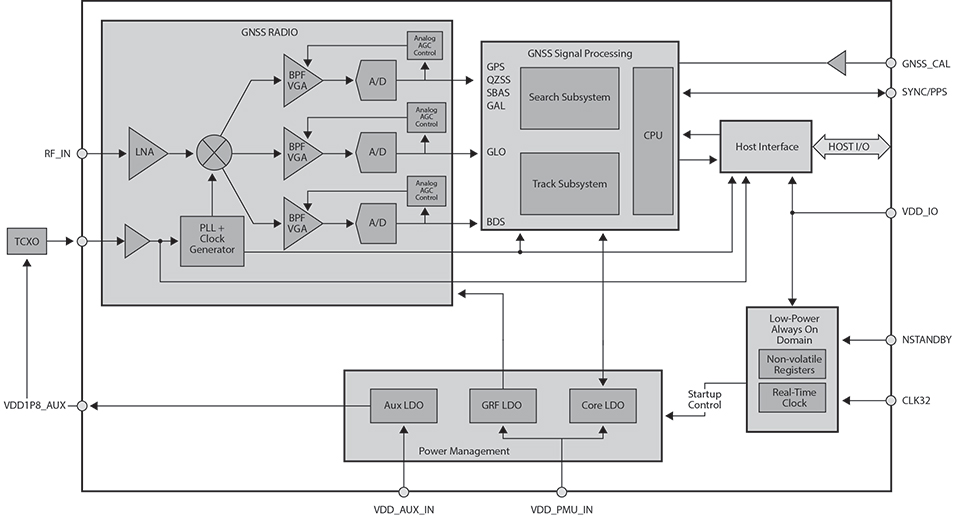
The complex IF output from the mixer is amplified by a transimpedance section followed by three parallel amplifier/filter/attenuator sections, one for GPS/Galileo/SBAS/QZSS, one for GLONASS, and one for BeiDou. The transimpedance section’s response is close to a simple pole but with a small amount of peaking. Each of the remaining sections is built with a single complex band-pass/band-notch section, followed by real poles and zeroes. Using real poles and zeroes considerably reduces the noise and bandwidth requirements of the amplifiers. The net effect is that the power consumption of the overall IF amplifier section is substantially reduced.
There are three parallel ΔΣ analog-digital converters (ADCs), one for each of the three IF sections. The ΔΣ ADC is a continuous-time, second-order, one-bit ΔΣ ADC, running at a sample rate of 395.75 Msps. The ΔΣ ADC comprises two operational amplifiers, two digital analog converters, and a quantizer. The ΔΣ ADCs are designed in such a way that the quantization noise is lowest not at zero frequency offset (DC), but at the offset frequency of the GNSS signal. The A/D samples are filtered with a third-order cascaded integrator-comb subsampled at 99.44 mega-samples per second. Additional finite impulse response (FIR) filters and subsampling to 33.1 MHz complete the sampling. The combined ΔΣ ADC and digital filtering provide more than 50 dB of dynamic range.
Digital processing at 33.1 MHz includes several filters that remove interference sources from the received radio signal and automatic gain control logic that adjusts the gain of the IF amplifiers to give an optimal signal level. A configurable 20-tap FIR filter is provided for each sample section and can be configured to remove wideband blockers. In addition, each section has eight narrowband, single-pole infinite impulse response filters for removing narrowband blockers.
Figure 1. Radio overview diagram.
Separate Search and Track Blocks
Separate search and track sections are employed to compute correlations between the three sample streams and multiple reference hypotheses. The three sample streams are buffered in memory to allow the search and track sections to process multiple correlations in parallel. Search employs a prime factor fast Fourier transform with a selectable size (1023, 2046, or 4092).
Search correlations are computed by first removing a hypothesis Doppler from a buffered set of samples and then combining a selectable number of code epochs. The filtered samples are translated to the frequency domain, multiplied by the frequency-domain representation of the desired PRN code, and finally translated back to the time domain. This process creates a coherent correlation vector for the entire code. The coherent correlation vector is non-coherently accumulated until the signal-to-noise ratio of the peak exceeds a detection threshold.
Track correlations are computed in the time domain by multiplying a multichip reference code by a set of buffered samples. Typically, the reference code is linearly delayed for N correlations to produce an N-sample coherent correlation vector. The correlation vectors are buffered to allow multiple filters to be processed in parallel. A coprocessor is used to run the filters. The outputs from the coprocessor provide estimates of code phase, Doppler, acceleration, data synchronization, data bits, signal power, and more.
All the buffering and multiple processing sections allow for multiple hypotheses to be tested in parallel. For example, on a tunnel entry, the attenuated signal can continue to be tracked while the search section tries to detect the full-power signal.
Secondary Code Resolution. Several constellations have secondary codes that limit the length of the coherent integration unless the code can be wiped. GLONASS has a 100-Hz Manchester code, BeiDou has a 1-kHz secondary code, and the Galileo Pilot has a 250-Hz secondary code. After the time accuracy drops below 1 millisecond, all of the secondary codes can be wiped in both search and track, so the coherent period can be optimized to maximize sensitivity and minimize measurement error. On a cold start, when time is unknown, it is best to first try to detect with coherent correlations less than the secondary code chip period.
When a signal is detected, the receiver either goes into track and computes correlations with longer coherent periods for multiple time hypotheses or continues in search with a longer coherence period and multiple time hypotheses. The search and track sections allow for either of these choices. For constellations like Galileo, the best choice is to remain in search. For others like BeiDou, it is best to move to track.
Benefits of Multi-GNSS Receivers
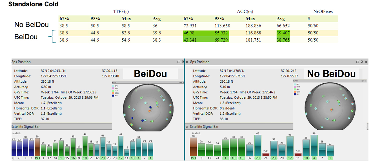
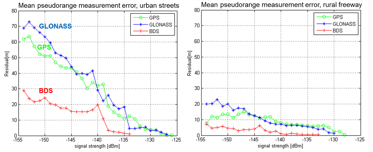
The ability to track all L1 constellations means that even in difficult environments, there are a sufficient number of satellites to produce a navigation solution. As can be seen from field-test results, not only are more satellites tracked, but more satellites with strong signals are tracked. The measurement errors of satellites received with strong signals will be smaller, leading to very low bit-error rates and allowing for a faster ephemeris collection. Field test results confirm that a receiver with BeiDou support achieves faster and more accurate fixes than a receiver without BeiDou support (see Figure 2).
Figure 2. A receiver with BeiDou support achieves faster and more accurate fixes than a receiver without BeiDou support.
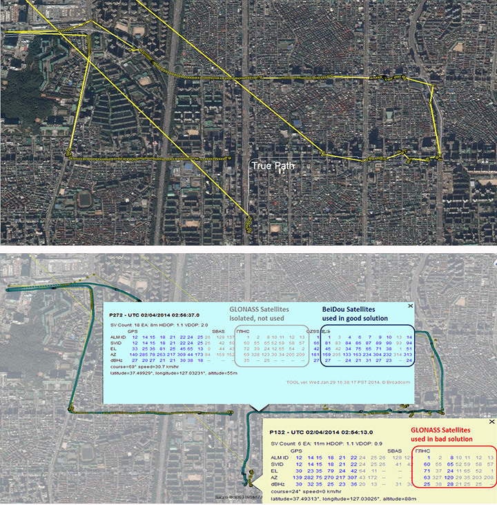
In addition to speed and accuracy improvements, more constellations provide a higher reliability. Recently, an upload error in the GLONASS constellation caused otherwise healthy satellites to report orbit errors of several kilometers. GPS/GLONASS-only systems could not completely isolate the faulty satellites. In difficult environments, there are not enough good satellites to isolate the faulty ones. With the addition of BeiDou, the faulty satellites were correctly isolated (Figure 3).
Figure 3. (Top) Seoul, South Korea, third-party GPS/GLONASS-only receiver; (bottom) Broadcom GPS/GLONASS/BeiDou receiver enables isolation of faults.
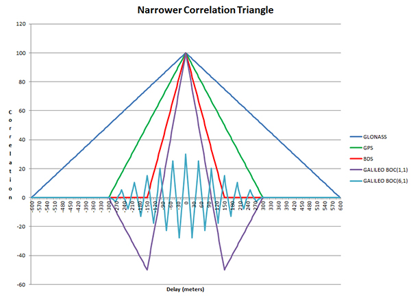
Each constellation adds unique improvements. Narrowing the correlation triangle allows for improved multipath rejection and more accurate pseudorange measurements (Figure 4).
Figure 4. Narrower correlation triangle.
GLONASS, with the slowest code rate, has the broadest correlation triangle. BeiDou, with the highest code rate, has a correlation triangle that is narrower than GPS. The BOC code on Galileo gives the narrowest correlation triangle. Field test results confirm the improved measurements (Figure 5).
GLONASS, the only FDMA constellation, has the least cross-correlation. GPS uses Gold codes to keep the cross-correlations between any of its satellites at a minimum. BeiDou and Galileo have lengthened their codes and added a secondary code to reduce cross-correlations.
Conclusion
Taking advantage of similarities in the L1 GNSS constellations together with careful design choices to minimize size and current consumption has enabled the creation of commercial GNSS system-on-chips that support all current GNSS L1 systems and meet the cost, size, and power requirements of cellular phones. The addition of new constellations like BeiDou and Galileo has significantly improved speed, performance, and reliability.
Acknowledgments
Javier de Salas, Frank van Diggelen, and John Hutson, all of Broadcom.
Manufacturer
The BCM4774 single-chip GNSS location hub for smartphones with Galileo support was designed by Broadcom Corporation.
Charles Norman is a technical director in the GNSS group at Broadcom Corporation. Previously, he worked on GNSS systems at Magnavox, Interstate, SIRF, and RFMD. He holds 39 issued patents on GNSS systems and has an M.A. in mathematics from the University of California-Los Angeles.
Andreas Warloe is a senior technical director in the GNSS group at Broadcom Corporation. He previously worked on GNSS receivers at Magellan, Leica Geosystems, IBM, and RFMD. He holds an M.S. in electrical engineering from the University of Southern California.
The United Nations and Russia’s space agency ROSCOSMOS are holding a workshop on ways to use GNSS for sustainable social and economic benefits. The workshop will be held May 18-22 in Krasnoyarsk, Russian Federation.
Current and planned projects that use GNSS technology, including the GLObalnaya NAvigatsionnaya Sputnikovaya Sistema (GLONASS) of the Russian Federation, for both practical applications and scientific explorations will be presented. Cooperative efforts and international partnerships for capacity-building, training and research, including the activities of the GLONASS learning center will also be presented.
The workshop program will include plenary sessions described below and also sufficient time for discussions among participants to identify the priority areas where pilot projects should be launched and examine possible partnerships that could be established. In addition, a half-day technical tour will be arranged by the Local Organizing Committee during the workshop.
The workshop is co-organized and co-sponsored by the International Committee on Global Navigation Satellite Systems, and hosted by the Reshetnev Information Satellite Systems Joint Stock Company.
Sessions include:
Session 1: Current and Planned GNSS and Satellite-Based Augmentation Systems
Session 2: GNSS-based Applications
Session 3: GNSS and Space/Atomospheric Weather Monitoring
Session 4: GNSS Reference Frames/Systems and Reference Station Networks
Session 5: Capacity building, training and education in the field of GNSS
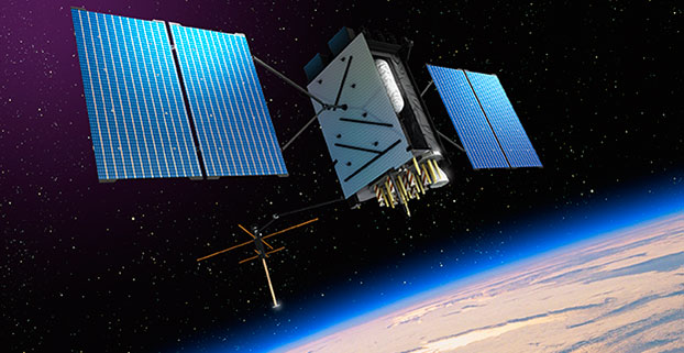
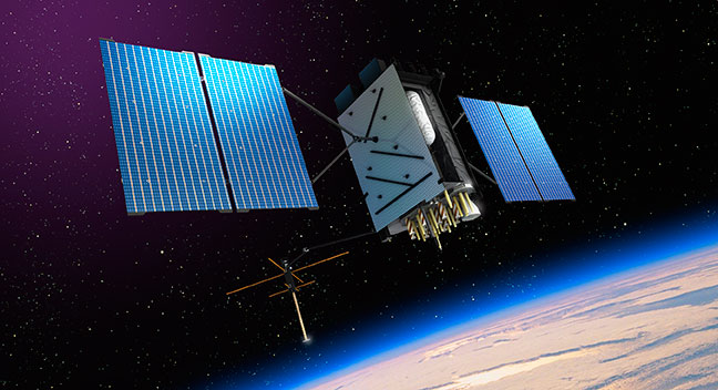
Artist’s rendering of GPS III satellite (courtesy of Lockheed Martin).
Raytheon Company and Lockheed Martin successfully completed the fourth of five planned launch and early orbit exercises to demonstrate new automation capabilities, information assurance and launch readiness of the U.S. Air Force’s next-generation GPS III satellite and Operational Control System (OCX).
Successful completion of Exercise 4, on Oct. 3, represents a key milestone demonstrating the end-to-end capability to automatically transfer data between Raytheon’s OCX and Lockheed Martin’s GPS III satellite. One additional readiness exercise, five launch rehearsals and a mission dress rehearsal are planned prior to launch of the first GPS III satellite with OCX.
The exercise used the latest baseline of Raytheon’s OCX Launch Checkout System (LCS) software featuring integrated information assurance functionality for the first time and the latest version of Lockheed Martin’s GPS III satellite simulator. Exercise 4 successfully demonstrated mission planning and scheduling capabilities with the simulated Air Force Satellite Control Network (AFSCN) for the first time, including a replan scenario that would occur in the event of a launch slip.
The system also automatically generated antenna pointing angles for the simulated AFSCN, which until now have been manually generated. Exercise 4 expands on three previous exercises, introducing maneuver planning and reconstruction capabilities, as well as advanced planning and scheduling with AFSCN assets. The automation of these capabilities will allow GPS operators to spend their time optimizing system performance rather than focusing on routine operations.
“As part of establishing the LCS Block 0 baseline, the completion of Exercise 4 demonstrates the capability of OCX to successfully support a GPS-III satellite launch in an information assurance hardened environment,” said Matthew Gilligan, Raytheon vice president and GPS OCX program manager. “Exercise 4 began the instantiation of vital OCX automation capabilities that give operators their time back in order to focus on mission critical activities, one of the important elements of a modernized GPS.”
“Launch Exercise 4 demonstrated the team’s ability to complete nearly 100 percent of the GPS III space vehicle 1 launch and early orbit mission sequence,” said Mark Stewart, vice president for Lockheed Martin’s Navigation Systems mission area. “The findings the team made during this robust launch exercise will help mature the processes, procedures, and tools necessary to enter our rehearsal phase and ultimately the launch and checkout mission.”
GPS III satellites will deliver three times better accuracy, provide up to eight times improved anti-jamming capabilities, and include enhancements that extend spacecraft life to 15 years, 25 percent longer than the newest Block IIF satellites. GPS III will be the first generation of GPS satellite with a new L1C civil signal designed to make it interoperable with other international global navigation satellite systems. The first GPS III satellite is currently undergoing integration and testing, with final space vehicle delivery planned for late 2015.
OCX is being developed in two blocks using a commercial best practice iterative software development process, with seven iterations in Block 1 and one iteration in Block 2. Exercise 4 was conducted using the recently completed Iteration 1.5 software, representing an early delivery of the final software baseline. Exercise 5, scheduled for 2015, will include critical information assurance features needed to support launch of the first GPS III satellite.
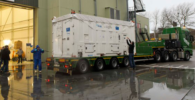
The latest Galileo satellite, formally known as FOC FM06, arrived at the ESTEC Test Centre in its protective container on Dec. 18, after traveling from OHB in Bremen, Germany. Photo: European Space Agency
The latest Galileo satellite has arrived at ESTEC, in the Netherlands, and is undergoing a full checkout to prove its readiness for space.
The satellite was carried by lorry from its manufacturer in Germany, cocooned within an environmentally controlled container. It arrived inside ESTEC’s cleanroom environment on Dec. 18. The container was then opened up to begin preparations for testing.
The first six Galileo satellites are already in orbit, launched in pairs in 2011, 2012 and August this year.
The last pair was delivered into the wrong orbit by a faulty upper stage, but the fifth satellite’s orbit has since been changed to allow checking of its navigation payload, which began at the end of November.
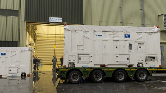
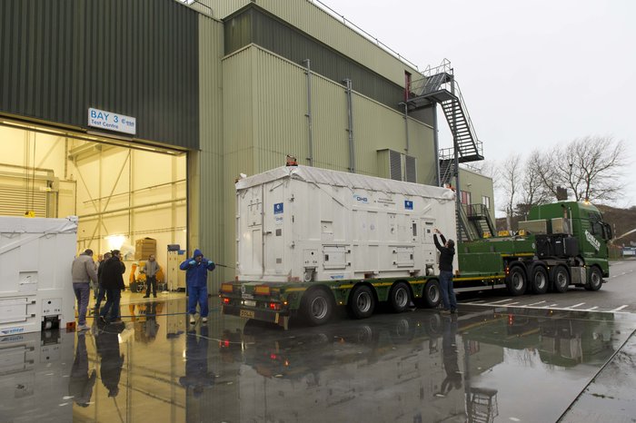
The sides and top of the Galileo satellite container were sprayed clean before it was taken inside the bay of the ESTEC Test Centre to keep any contamination from entering the pristine cleanroom. Photo: European Space Agency
Meanwhile, down on the ground, production of further satellites continues steadily, taking the Galileo series into double figures overall.
Following on from the first four In-Orbit Validation satellites, 22 of these Full Operational Capability satellites are being built by OHB in Bremen, Germany, with navigation payloads from SSTL in Guildford, UK.
Numbered Flight Model 6, or FM06 for short, this latest of the newer satellites is now reunited under the test centre’s roof with three others. FM03 and FM04 have completed their acceptance testing, culminating in the weeks-long thermal-vacuum test. Each satellite was subjected to the same vacuum and extreme temperature conditions experienced in orbit, as well as radio-frequency testing of their navigation payloads and antennas inside an anechoic chamber isolated from the external universe. This pair is now in storage in the centre pending the results of their concluding acceptance review.
The other satellite, FM05, recently ended its own thermal-vacuum trial. It is now being reconfigured for radio-frequency testing, planned to take place after the Christmas break. The latest unboxed Galileo satellite will undergo its own thermal–vacuum test in January.
ESTEC is an essential stop on the way to space for Galileo. It is equipped with all the facilities needed to simulate space conditions under a single roof, including an acoustic chamber, earthquake-strength shaker tables, and anechoic and vacuum chambers, along with a range of specialised measuring equipment.
Once ESTEC gives the satellites its stamp of quality then they are in principle ready to be flown to Europe’s Spaceport in Kourou, French Guiana. ESA and the European Commission are currently deciding on the launch schedule for these next Galileos.
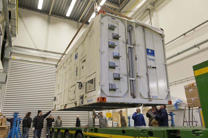
The container containing the latest Galileo satellite, FOC FM06, was carefully hoisted off the lorry that carried it from OHB in Bremen, Germany. Its underside was then carefully cleaned before it was taken out of the bay into the cleanroom environment. Photo: European Space Agency
Will Be Employable for Surveying, Precise Positioning, and Geodesy
By Peter Steigenberger and André Hauschild, German Aerospace Center (DLR) / German Space Operations Center
The first Full Operational Capability (FOC) Galileo satellite started transmitting L-band navigation signals on November 29, 2014. Based on data collected by a global network of GNSS tracking stations of the Cooperative Network for GNSS Observation (CONGO) and the Multi-GNSS Experiment (MGEX) of the International GNSS Service (IGS), we determined that an E1 signal with pseudorandom noise code (PRN) E18 was first tracked at the station LLAG (La Laguna, Tenerife, Canary Islands) at 06:08 UTC. A few moments later, the satellite’s transmissions were also tracked at other MGEX stations including the E5a, E5b, and E5 AltBOC signals. Based on the computed satellite visibility at various tracking stations, the satellite could be positively identified as GSAT0201, also known as Galileo FOC-FM1 or Galileo 5 with COSPAR ID 2014-050A and NORAD ID 40128.
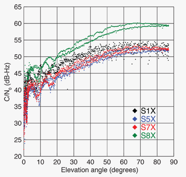
FIGURE 1 shows the carrier-to-noise-density ratio (C/N0) of the E18 signals tracked at the CONGO/MGEX station SIN1 (Singapore, using a Trimble NetR9 receiver with a Leica AR25.3 antenna). We selected the signals from this station for analysis due to an E18 pass occurring close to the zenith and covering almost the full range of elevation angles. The E5a and E5b signals (S5X and S7X RINEX identifiers) show very similar performance, whereas the C/N0 values of the E1 signal are 1–2 dB-Hz higher. The C/N0 values of the E5 AltBOC signal (S8X) reach 60 dB-Hz at high elevation angles, which is about 6 dB-Hz higher than the other signals.
Figure 1. Galileo E18 carrier-to-noise-density ratio for the CONGO/MGEX station SIN1 (Singapore).
The first pair of Galileo FOC spacecraft was launched on August 22 with a Soyuz launcher from the Guiana Space Centre, Kourou, French Guyana. Due to a malfunction of the Fregat upper stage, the satellites were injected into elliptical orbits with an inclination of about 49° instead of near circular orbits with 55° inclination. In November, the perigee of the first FOC satellite was raised by about 3,500 kilometers by a series of 11 maneuvers with a corresponding reduction in orbit eccentricity from 0.23 to 0.16.
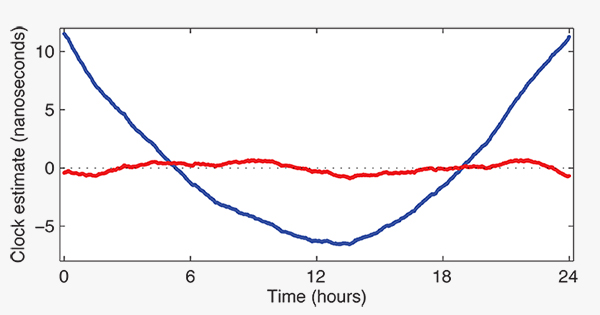
E18 has been included in the precise orbit and clock solutions of the MGEX analysis center at Technische Universität München (TUM) in Munich, Germany, since December 5. FIGURE 2 shows the detrended estimates of the active Galileo E18 clock for December 7. The presence of a pronounced quadratic term as well the large drift of 33.9 microseconds per day indicate that the active clock is a rubidium atomic frequency standard rather than a more precise passive hydrogen maser. The FOC satellites carry two of each kind of clock.
Figure 2. Galileo E18 clock estimates for December 7, 2014, with respect to the hydrogen maser at the Ottawa IGS station (NRC1) after removing an offset and drift (blue) or a second order polynomial (red).
The TUM orbit and clock product allows researchers to again compute dual-frequency positioning solutions using only Galileo observations, as the In-Orbit Validation satellite E20 has not transmitted an E5 signal since May, when a power anomaly left the satellite with the capability to only transmit an E1 signal. Furthermore, E20 currently does not transmit a navigation message.
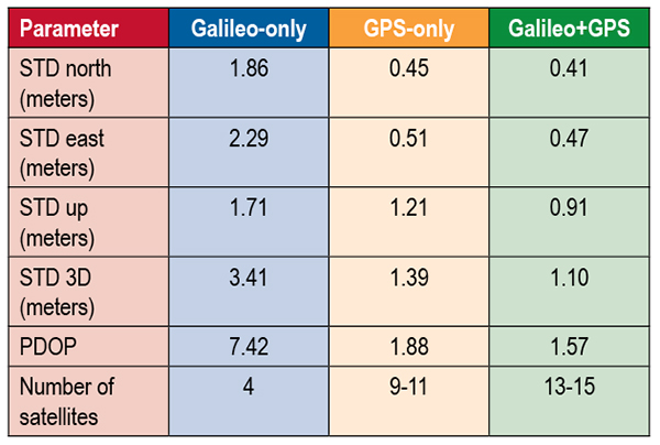
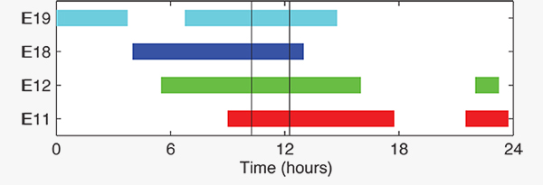
TABLE 1 shows the scatter of single-point positioning using pseudorange (code) observations from the MGEX station MAS1 (Maspalomas, Gran Canaria, Canary Islands) for a Galileo-only, a GPS-only, and a combined Galileo+GPS solution for December 6. At an elevation cut-off angle of 10°, four Galileo satellites were visible from 10:15 until 12:25 UTC (see FIGURE 3). The GPS-only solution covers the same time interval. The start time is not limited by the cut-off angle but an E18 transmission outage from 3:45–10:15 UTC.
TABLE 1. Single point positioning results for the MGEX station MAS1 (Maspalomas) for December 6, 2014.Figure 3. Galileo visibility at the MGEX station MAS1 (Maspalomas) on December 6, 2014. The time period considered in the single-point positioning is indicated by vertical lines.
We used an ionosphere-free linear combination of Galileo E1 and E5 AltBOC code observations and GPS L1 and L2 code observations with a 30-second sampling interval. As the Galileo-only solution suffered from position dilution of precision (PDOP) values of up to 830, a total of 32 epochs with PDOP values greater than 25 were excluded. The geometry of the remaining epochs is still pretty unfavorable. At a mean PDOP value of 7.4, the standalone position solution exhibits a 3D standard deviation (STD) error of 3.4 meters. Use of the Galileo satellites in a combined GPS+ Galileo solution improves the positioning performance. In particular, the height component benefits from the inclusion of the four Galileo satellites with a standard deviation improvement of 25 percent.
Despite the orbit injection error, the new Galileo FOC satellite has now been successfully activated and added to the Galileo constellation. Unfortunately, the current orbit is incompatible with the standard Galileo almanac format, which may cause restrictions for some commercial receiver types.
Nevertheless, the satellite can already be tracked by a wide range of geodetic receivers with existing firmware versions and it will, in fact, be possible to use the new satellite for diverse applications in surveying, precise positioning, and geodesy, as well as in general multi-GNSS studies. We now look forward to the activation of the second FOC satellite, which can be expected in early 2015 and will, for the first time, offer multi-frequency signals from a total of five Galileo satellites.
Sanctions Delay GLONASS-K2
According to Nikolai Testoyedov, the CEO of Information Satellite Systems Reshetnev, manufacturer of the GLONASS satellites, the company will now produce nine GLONASS-K1 satellites.
“For a smooth transition to a multi-functional group and due to issues with the very complex GLONASS-K2 satellites, we decided to continue with the GLONASS-K1 intermediate range of satellites, and we are preparing for the launch of nine units of this series,” he said.
He recalled the original plan was to launch two K1 satellites and then move to GLONASS-K2 satellites.
“In the beginning, really, we wanted after the two GLONASS-K1 satellites No. 11 and 12, to go for the launch of more advanced GLONASS-K2 devices. But, unfortunately, the plans had to be adjusted somewhat because of the sanctions restricting the delivery of radiation-resistant electronic components from the West. We have to put a hold on the in-depth development of technical and technological documentation and that delays us in terms of moving ahead by at least a year or two,”he said.
Reported by the Russian magazine Vestnik GLONASS, and relayed by Richard Langley’s CANSPACE listserv.
GNSS Mandates Would Violate Trade Agreements
A U.S. government representative stated at an international satnav forum that mandating use of specific GNSS services for applications such as air-traffic control, freight shipments, emergency calling, and road tolling could violate the terms of World Trade Organization (WTO) agreements that many nations, including all six GNSS providers, have signed.
Regional mandates already exist for GLONASS in Russia and BeiDou in China, and have been suggested and extensively discussed in Europe, as a way of stimulating the market adoption of Galileo receiver chipsets, thus recouping some of the massive public investment in the satnav system.
The presentation occurred during the Ninth Meeting of the International Committee on Global Navigation Satellite Systems (ICG), held Nov. 10–14, 2014, in Prague, Czech Republic.
Jason Kim, a senior policy analyst at the U.S. Department of Commerce, stated that the United States and the European Union already enjoy a productive dialog on GNSS trade issues under the 2004 U.S.-EU Agreement on GPS-Galileo Cooperation. In that agreement, both parties agreed to consult before establishing GNSS standards, certification requirements, regulations, mandates; affirmed their non-discriminatory approach with respect to GNSS trade; and established a working group to consider non-discrimination and other trade related issues.
Finally, the United States and the European Union recognized and reiterated in 2004 their commitments to WTO rules including those governing technical barriers to trade, specifically, that there would be no goods discrimination based on non-tariff measures such as regulations, standards, testing, or certification.
Kim made the remarks in the course of his presentation titled “GNSS Market Access.” He told GPS World that his presentation was directed less at the European Union, which has been conscientious of its WTO commitments, and more towards the rest of the ICG members, including non-provider nations that may be asked by GNSS providers to mandate specific systems.
“To promote adoption of their systems,” Kim stated, “GNSS providers are considering/implementing equipage mandates for various applications: aviation, motor-carrier and HAZMAT vehicle tracking, car accident reporting (eCall/ERA-GLONASS), and emergency phone calls (E112).
“The United States recommends technology-neutral, performance-based standards,” Kim continued, giving as example the U.S. E911 rules that specify a required positioning accuracy and then allow wireless carriers to choose the best technical solutions according to their lights.
The U.S. government presentation at ICG revealed particular concern that regulations under consideration could adversely affect the sales of U.S. GPS-enabled hardware in many industry sectors. All members of the WTO, including the six GNSS providers on the ICG, are bound to a range of trade agreements designed to promote open-market access, all cited in the Prague ICG presentation: the General Agreement on Tariffs and Trade (GATT), the Agreement on Technical Barriers to Trade (TBT), and the General Agreement on Trade in Services (GATS). The United States, Europe, Japan, and 12 others are also parties to the WTO Agreement on Government Procurement (GPA).
European Commission officials have publicly and recently stated that they are considering how to stimulate Galileo use, in particular through regulatory measures requiring that navigation equipment be installed on aircraft, automobiles, and other platforms.
“Requiring specific systems arbitrarily prevents or penalizes imports of goods having perfectly functional GNSS capability,” said Kim. “WTO members must comply with TBT obligations in setting technical regulations.”
He concluded his presentation by requesting that the ICG Providers’ Forum add GNSS market access to its future agenda for discussion, and consider developing a new principle on market access for future adoption.