Category: GNSS

  • Kinexon Wins 10th European Satellite Navigation Competition with Athlete Tracking Analysis

    Kinexon Wins 10th European Satellite Navigation Competition with Athlete Tracking Analysis

    Photo: Kinexon

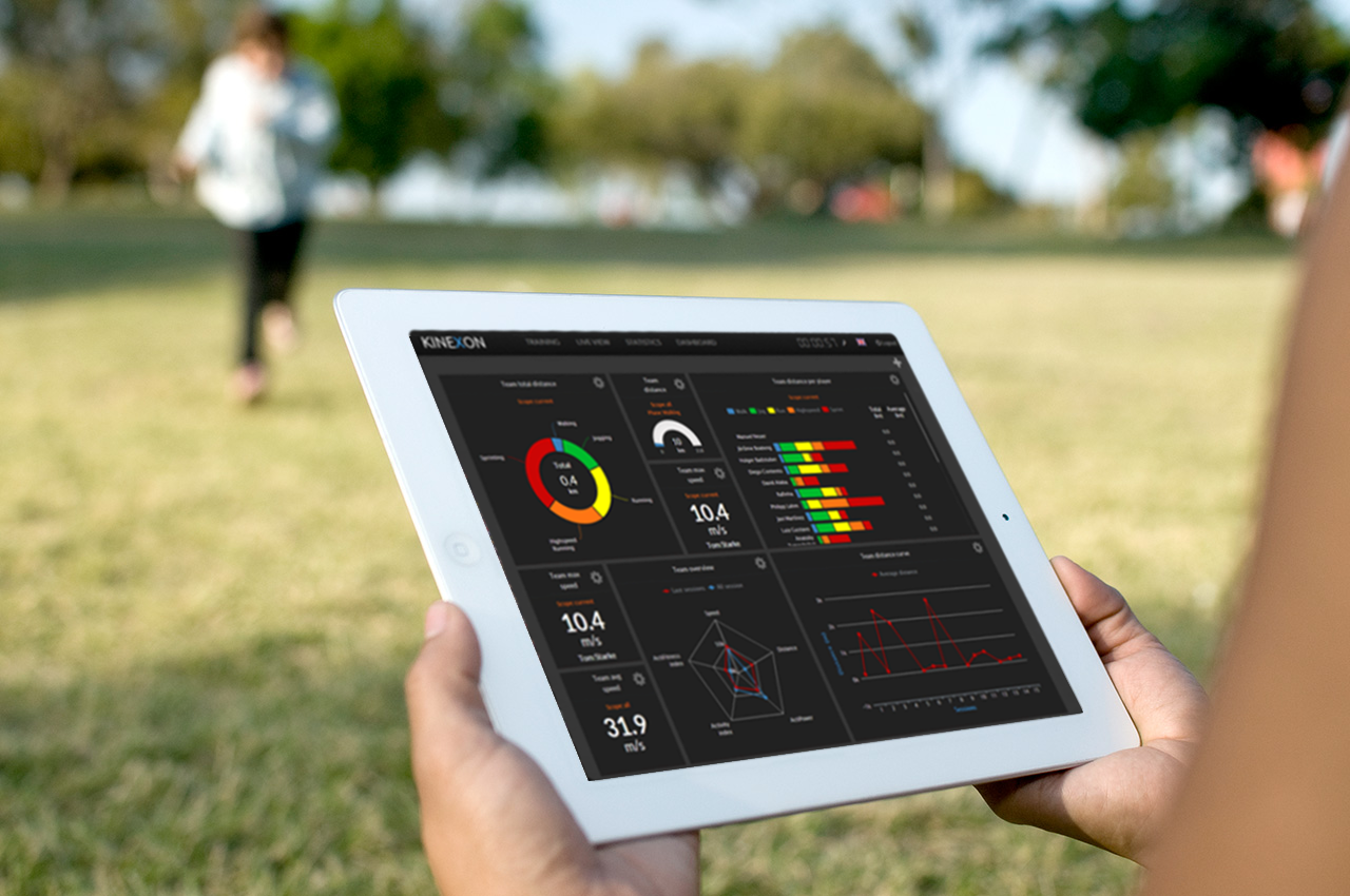
    Online analysis of athletes’ tactical, technical, and physical capability is the focus of this year’s newly named Galileo Master, Kinexon GmbH.

    The 10th European Satellite Navigation Competition (ESNC) recognized the best products, services, and innovations that facilitate the use of satellite navigation in everyday life. At the 2013 awards ceremony, prizes worth a total of about EUR 1 million were presented in 32 categories. The ceremony helped kick off the European Space Solutions conference, which is taking place November 5-7 at Alte Kongresshalle München.

    ESNC 2013 gave participants from all around the world the chance to vie for any one of 25 regional prizes. In addition, topic-specific special prizes were sponsored by the following partners: the European GNSS Agency (GSA), the European Space Agency (ESA), the German Aerospace Center (DLR), and — for the first time this year — the European Patent Office (EPO) and Metaio GmbH. Students and research assistants were also encouraged to submit their ideas to the ESNC University Challenge.

    Athletic analysis is playing an increasingly important role in modern sport training. The underlying idea — known as the Hawthorne effect — is simple: if you can measure your performance, you can also improve it. Following this principle, two research assistants from Technische Universität München (Germany) founded the company Kinexon GmbH at the ESA Business Incubation Centre Bavaria and developed a cloud-based solution for analyzing and visualizing training data on mobile devices.

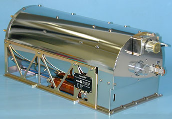
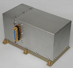
    Kinexon’s solution kits athletes out with a small, portable location sensor and feeds the resulting data into the cloud by means of a stationary base antenna. This enables users to track and analyze performance parameters and tactical movements down to the centimeter in real time.

    In particular, however, it was the solution’s user-friendliness during training and relatively low cost (compared to the camera-based systems commonly seen today) that won over the international jury of experts in the European Satellite Navigation Competition. So far, the high price of such systems has limited their use to professional sport; Kinexon’s system will now give amateur clubs the chance to benefit from adding online analysis to their training activities, as well.

    Along with the sport sector, this flexible satellite-based localization system also exhibits huge potential in tapping into further markets, including healthcare, logistics, and unmanned aerial vehicles (UAVs). “We’re pleased to be supporting Kinexon at ESA BIC Bavaria,” affirms Thorsten Rudolph, CEO of Anwendungszentrum GmbH Oberpfaffenhofen. The Kinexon system, the first version of which is set for market launch in November 2013, managed to edge out more than 400 other ESNC entries from nearly 50 countries.

    Gerd Gruppe, member of the Executive Board, German Aerospace Center (DLR), conferred the EUR 20,000 grand prize on Kinexon GmbH founders Oliver Trinchera and Alexander Hüttenbrink.

    “DLR sets great store in technology transfer,” Gruppe said. “After all, innovations form the basis of economic success and hold considerable potential for society. The ESNC has developed into a driving force behind the innovative use of satellite navigation technologies and a starting point for numerous successful start-ups in Germany, Europe, and the rest of the world.”

    Winners of the 10th European Satellite Navigation Competition

    In addition to the overall winner, the Galileo Master, the 10th European Satellite Navigation Competition rewarded Special Prizes in seven different categories and 25 prizes to regional winners.

    Special Prize Winners 2013 
    GSA :: The most promising EGNOS application idea
    Jelle Reichert, JOHAN, The Netherlands :: JOHAN: the Digital Oracle for Field Sports, Including GNSS Player Tracking in Real Time
    Keywords: Mobile Location Based Services, sports,  real-time tracking, health
    ESA Innovation Prize & 2nd in Overall Ranking
    Jan Walter Schroeder and team, SenSovo, Germany :: Sensovo Navipal: A New Way to Feel Directions
    Keywords: tactile navigation, wearable technology, tourism, outdoor sports, visually impaired
    DLR :: Robust GNSS – Safety for Success
    Bastiaan Ober and John Wilde, Integricom, DW International, The Netherlands :: Galileo-Based Ionospheric and Interference Monitoring for Aviation
    Keywords: signal security, real-time monitoring, aviation,  interference
    EPO :: Best Patented Innovation
    Gaël Scot and team, CNES, France :: Two Patents for Improved Galileo System Performance
    Keywords: signal security, patents, high-end GNSS receivers
    Metaio :: The most innovative location-based Augmented Reality application
    Steve Lee and team, Stevenson Astrosat, United Kingdom :: WinterVision: Augmented Reality for Winter Road Safety
    Keywords: augmented reality, road safety, driver assistance system, emergency response
    University Challenge & Portugal
    Luis Gomes and Filipe Sousa, Outcapsa, Portugal :: GeoAgenda: Innovative Geo-located Agenda Concept
    Keywords: LBS, smart personal organiser, meeting tool
    GNSS Living LabPrize & North Rhine-Westphalia / Germany & 3rd in Overall Ranking
    Adalbert Rajca and Yasotharan Pakasathanan , ampido GmbH, Germany :: Ampido: The Car Park in Your Pocket
    Keywords: Location Based Services, smart city application, park-sharing, share economy


    Regional Prize Winners 2013
    Aquitaine/France
    Romain Desplats and team, CNES, France :: Physiotrack: Track Your Physical Progress
    Keywords: sports tracking, health, performance monitoring, physical exercise forecast
     Arab Middle East & North Africa (MENA)
    Hussain Saleh, Ghent University, Belgium :: A Generic GNSS Network for Disaster MonitoringKeywords: emergency management, disaster monitoring, big data, artificial intelligence
    Austria
    Dr Clemens Strauß and Gernot Hollinger, Strauß & Hollinger : GeoIT OG, Austria :: ENViGUARD: The App That Helps Keep Your City Clean
    Keywords: smart waste management, crowdsourcing, LBS, public health, pollution control, environmental protection
    Baden-Württemberg / Germany
    Erich Franke and team,  AFUSOFT Kommunikationstechnik GmbH, Germany :: SaltHawk: Innovative Winter Road Safety System
    Keywords:  road safety, environmental protection, road service management
    Bavaria / Germany & Overall Winner
    Dr Oliver Trinchera and Dr Alexander Hüttenbrink , KINEXON GmbH, Germany :: KINEXON: Precise Localisation and Sports Monitoring
    Keywords: precise tracking, wearable technology, sports, health, logistics
    Bulgaria
    Nikolay Staykov and team, Mobilly, Bulgaria :: Mobilly: A Next-Generation Travel Planner
    Keywords: LBS, travel planner, local discount campaigns, couponing
    Catalonia / Spain
    Rafael Olmedo and Carlos Barreto, GEKO NAVSAT, SpainNAVMATE: The Low-Cost Safety Solution for the Great Outdoors
    Keywords: wearable technology, emergency management, outdoor navigation, outdoor sports
    Czech Republic
    Jiří Mikoláš and team, Be interactive, Czech Republic :: Augmented Prague: The Innovative Sight Seeing App
    Keywords: Augmented Reality, AR, LBS, tourism, city guide


    Estonia
    Mari Loorman, Estonia :: LASIK: Optimising Children’s Physical Activity
    Keywords: children’s health, physical activity, computer addiction
    Flanders / Belgium
    Joeri Spitaels and team, QraQon, Belgium :: Winnetou: Improved Security for Freight Wagons
    Keywords: freight tracking, transport security, solar-powered
    Gipuzkoa / Spain
    Jon Sánchez Ugarte, OnSiteBIM, Spain :: BimOn! Making Building Smarter with AR
    Keywords: Augmented Reality, AR, construction sites, building models, LBS
    Hesse / Germany & 3rd in Overall Ranking
    Lukas Wagner and team, Notificatio UG, Germany:: AlarmApp: Location-based Emergency Notification System
    Keywords: emergency management, volunteer fire fighters, LBS
    Ireland
    Paula Kelleher and James Mannix, Geomanics Ltd, Ireland :: CarSafari: Every Trip an Adventure
    Keywords: in-car entertainment, tourism, education, location-based advertising
    Japan
    Hitomi Inaba and team, University of Tokyo, Japan :: TrustSync: Secure Time and Frequency Synchronisation
    Keywords: high precision, signal security, synchronisation, GNSS receivers, financial networks
    Lithuania
    Saulius Rudys and Mantautas Rudys, Lithuania :: Improved Indoor and Underground Navigation Accuracy
    Keywords: indoor navigation, GNSS repeater, precise navigation
    Lombardy / Italy
    Mirko Antonini and Alessandro Di Felice, SpaceEXE Srl, Italy :: COPPI: Monitoring and Tracking of Cyclists
    Keywords: professional cycling teams, sports tracking, health, real-time performance monitoring
    Mexico
    Victor Jose Gatica-Acevedo and team, National Polytechnic Institute, Mexico :: AMBER Alert: Recovering Lost Children Through GNSS Integration
    Keywords: seach and rescue, LBS, notification, tracking
    The Netherlands
    Willem Folkers, Folkline, The Netherlands :: The Anti-Spoofing GNSS Receiver
    Keywords: signal security, safety critical applications, Galileo PRS (public regulated service)
    Nice-Sophia Antipolis / France
    Yann Hervouet and team, Instant System, France :: Real-Time Solutions for Public Transport PassengersKeywords: real-time trip planner, smart public transport, real-time schedule information
    North Rhine-Westphalia / Germany & GNSS Living Lab Prize & 3rd in Overall Ranking
    Adalbert Rajca and Yasotharan Pakasathanan , ampido GmbH, Germany :: Ampido: The Car Park in Your Pocket
    Keywords: Location Based Services, smart city application, park-sharing, share economy
    NorwayHarald Skinnemoen and team, AnsuR, Norway :: GNSS-Enabled Do-It-Yourself Insurance Claims                 
    Keywords: LBS, insurance claims, geo-tagged images, crowdsourcing
    Øresund / Denmark & Sweden
    Andreas Ekengren and team, PingPal AB, Sweden :: Pingpal: Privacy-Protected Positioning for Your App
    Keywords: social networking, cloud solution, privacy protection
    Portugal & University Challenge
    Luis Gomes and Filipe Sousa, Outcapsa, Portugal :: GeoAgenda: Innovative Geo-located Agenda Concept
    Keywords: LBS, smart personal organiser, meeting tool
    Switzerland
    Che-Tsung Lin and team, Industrial Technology Research Institute, Taiwan :: See Through: Driving as You’ve Never Seen Before
    Keywords: driver assistance, V2V communication, road saftey
    United Kingdom
    Georgios Michalakidis and team, ManagePlaces Limited, United Kingdom :: ManagePlaces: Location-Based Project Management
    Keywords: field staff management, LBS, mobile workflow management, cloud solution


  • Galileo Satellites Put to the Test

    Galileo Satellites Put to the Test

    The main antenna of the second Galileo Full Operational Capability (FOC) satellite being inspected with a flashlight in advance of mass property testing during August 2013.
    The main antenna of the second Galileo Full Operational Capability (FOC) satellite being inspected with a flashlight in advance of mass property testing during August 2013.

    Europe’s next pair of Galileo satellites have been the focus of a busy autumn at the European Space Agency’s (ESA’s) technical centre in the Netherlands, continuing a full-scale campaign to ensure their readiness for space.

    The first Galileo Full Operational Capability (FOC) satellite, FM1, seen beside the Phenix test chamber being readied for its five-week long thermal vacuum testing in October 2013.
    The first Galileo Full Operational Capability (FOC) satellite, FM1, seen beside the Phenix test chamber being readied for its five-week long thermal vacuum testing in October 2013.

    With the first four Galileos already in orbit, these new versions are the first two of a total 22 Full Operational Capability (FOC) satellites being built by OHB in Germany with a payload from Surrey Satellite Technology Ltd. in the UK.

    The second satellite joined its predecessor in mid-August at ESA’s European Space Research and Technology Centre in Noordwijk. This is the largest spacecraft testing site in Europe, with a full range of space simulation facilities under a single roof in cleanroom conditions. A wide range of tests have been performed on the two satellites.

    The first of the two satellites is now midway through a five-week immersion in vacuum and temperature extremes that mimic the conditions it faces in space. This thermal-vacuum test takes place inside a 4.5-meter diameter stainless-steel vacuum chamber called Phenix. An inner box called the thermal tent has sides that are heated to simulate the Sun’s radiation or cooled down by liquid nitrogen to create the chill of Sunless space.

    Second Galileo Full Operational Capability (FOC) satellite being prepared for acoustic testing, simulating the noise of a rocket launch, inside the Large European Acoustic Facility, LEAF, of the ESTEC Test Centre in early September 2013.
    Second Galileo Full Operational Capability (FOC) satellite being prepared for acoustic testing, simulating the noise of a rocket launch, inside the Large European Acoustic Facility, LEAF, of the ESTEC Test Centre in early September 2013.

    The newly arrived satellite first underwent a mass property test — measured to check its center of gravity and mass are aligned within design specifications. The more precisely these are known, the more efficiently the satellite’s orientation can be controlled with thruster firings in orbit, potentially elongating their working life by conserving propellant.

    Meanwhile, its predecessor left the wider universe behind in the Maxwell Test Chamber. Shielded walls blocking out all external electrical signals and spiky, radio-absorbing anechoic material lining the chamber enable electromagnetic compatibility testing. Isolated within the chamber as though floating in infinite space, the satellite could be switched on to check all its systems can operate together without interference.

    September saw the second satellite undergo acoustic testing in the Large European Acoustic Facility, LEAF, effectively the largest sound system in Europe. The first satellite submitted to this trial just a few weeks before. A quartet of noise horns are embedded in one wall of this 11-meter-wide, 9-meter-deep and 16.4-meter-high chamber, generating sound by passing nitrogen gas through the horns, surpassing 140 decibels.

    Galileo Full Operational Capability (FOC) satellite first flight model, FM1, being prepared for 'passive intermodulation testing' within the Maxwell electromagnetic test facility inside the ESTEC Test Centre at the end of August 2013.
    Galileo Full Operational Capability (FOC) satellite first flight model, FM1, being prepared for ‘passive intermodulation testing’ within the Maxwell electromagnetic test facility inside the ESTEC Test Centre at the end of August 2013.

    Accelerometers placed within the satellite checked for potentially hazardous internal vibration during this trial by sound. Then the spacecraft was vibrated on the shaker tables, simulating the violent forces of a rocket launch.

    Up-and-down vibration on the QUAD shaker followed by side-to-side shaking on the horizontal shaker, with data gathered across hundreds of channels.

    The satellite was then connected to the dispenser that will hold it during launch to simulate the separation at the end of its climb to orbit. This separation is triggered by firing a pyro device which then pushes the satellite away from the dispenser. This demonstration took place last month.

    “There will always be two Galileo satellites being tested at the ESTEC Test Centre for the next few years,” explains Giuliano Gatti, the head of the Galileo Space Segment Procurement Office.

    “As the Galileo constellation takes shape, ESTEC will remain an essential part of each satellite’s pathway to space, between the end of manufacturing in Germany and UK and the launch by Soyuz ST-B or Ariane-5 from Europe’s Spaceport in French Guiana.

    “Of course, the testing on these initial FOC satellites is especially rigorous because we are validating the overall design. The Galileo satellites to follow will undergo more streamlined ‘acceptance’ testing instead.”

    The next two satellites are in final assembly at OHB in Germany, scheduled to reach ESTEC early next year, as these first two satellites head off to French Guiana for launch.

    Galileo Full Operational Capability Flight Model 2, FM2, satellite's main L-band antenna used for broadcasting navigation messages, seen during preparation for a mass property test at the ESTEC Test Centre at the end of August 2013.
    Galileo Full Operational Capability Flight Model 2, FM2, satellite’s main L-band antenna used for broadcasting navigation messages, seen during preparation for a mass property test at the ESTEC Test Centre at the end of August 2013.
  • Fourth ESA Colloquium on Galileo Coming in December

    The Fourth International Colloquium on Scientific and Fundamental Aspects of the Galileo Programme will be held in Prague, Czech Republic, December 4–6.

    Since 2007, the worldwide scientific community has met every two years to discuss the possibilities for boosting the scientific use of Galileo and for contributing to the development of the GNSS.

    The event is always organized in one of the 20 European Space Agency’s Member States, and makes an essential contribution to ESA’s implementation and definition of the evolution of the European GNSS. The gathering of major academic players provides a scientific reference for institutional executives and industry, as well as offering a unique platform for promoting innovative GNSS initiatives at large.

    The colloquium focuses on four major areas of research:

    • Scientific applications in meteorology, geodesy, geophysics, space physics, oceanography, land surface and ecosystem studies, using either direct or reflected signals, differential measurements, phase measurements, radio occultation measurements, using receivers placed on the ground, in aircraft or on satellites.
    • Scientific developments in physics, dealing with future GNSS, particularly in testing fundamental laws in astronomy and in quantum communication. Relativistic reference frames and relativistic positioning will be addressed.
    • Aspects of metrology such as reference frames, onboard and ground clocks, and precise orbit determination.
    • Scientific aspects of satellite navigation and positioning such as signal propagation, tropospheric and ionospheric corrections and the means to model and mitigate multipath and interference.

    The various possibilities to use navigation satellites such as Galileo for scientific purposes will be reviewed and the use of scientific applications to contribute to make the most of the present systems and define their evolution will be scrutinized.

    The conference is being organized as a series of plenary talks and two parallel half-day sessions.

    For more information or to register, visit the colloquium website.

  • Cambridge Consultants Introduces Tractor Collision Avoidance Technology

    Cambridge Consultants introduces radar-based technology detection system to help agricultural vehicles avoid collisions. The new radar system helps prevent this by protecting the perimeters of the vehicle from potential hazards – giving audible and visual warnings to the driver.

    CambridgeConsultants1

    “We have identified a huge demand for this type of agricultural technology as we see a continued increase in advanced farming techniques in the face of impending population growth and food shortages,” said Gary Kemp, programme director at Cambridge Consultants. “We’ve created practical technology that’s simple to operate and install but is also low cost and incredibly effective.”

    According to the announcement, the radar units are designed to be installed on the front and rear of a vehicle as well as on the boom ends, and can detect multiple collision hazards in a wide field of view which maximises coverage. The technology can process many different moving and stationary obstacles – and instantly send an alert to the driver to warn of a potential collision. The low-frequency (5.8GHz) system is based on standard manufacturing principles, making it a cost-effective solution. The patented short-range radar technology provides unbeatable performance from a compact, low-cost sensor. The sensor simultaneously tracks multiple objects in 3D over a wide field of view and up to 30m range. Real-time collision prediction algorithm identifies hazards early, giving the driver ample time to take avoiding action

    The company will be showcasing its latest farming technology at the Agritechnica International Exhibition, November 12-15, in Hanover, Germany, hall 17, stand C38.

  • New Structure for GLONASS Nav Message

    New Structure for GLONASS Nav Message

    Photo: GLONASS

    Russian scientists propose a new code-division multiple-access signal format to be broadcast on a new GLONASS L3 signal. Once implemented across the modernizing GLONASS constellation, this will facilitate interoperability with — and eventually interchangeability among — other GNSS signals. The flexible message format permits relatively easy upgrades in the navigation message, if required.

    By Alexander Povalyaev

    Navigation messages (NM) developed and broadcast so far, by both GPS and GLONASS, are fixed, regular structures including pages (frames), subframes (rows), and words. Despite their simplicity, such structures are very conservative. The only possibility to update such navigation messages is restricted to the use of previously allocated backup frames. Increasing numbers of such frames make for ineffective use of navigation message transmission capacity. Conversely, the relatively small number of backup frames restricts the potential for future navigation-message upgrades.

    This concept is illustrated by the next two figures. Figure 1 shows the structure of GPS NM superframe.nBackup subframes are showed in bold dots. We can see that from 125 subframes of a GPS NM with a duration of 12.5 minutes, 14 subframes (or roughly 11 percent) are backup ones.

    Figure 1. Backup of GPS NM superframe.
    Figure 1. Backup of GPS NM superframe.

    Figure 2 shows the structure of GLONASS NM. Backup frames with indication of bit numbers are shown by unhatched fields. In the GLONASS superframe with a duration of 2.5 minutes, these bits occupy only about 3 percent.

    If we assume a data equivalence transmitted in the GLONASS and GPS navigation solutions, we can see that data transmission rate in GLONASS is five times as much as in GPS. This is explained by the higher redundancy of the GPS NM. Besides the roughly 11 percent of subframes kept in backup, the GPS superframe reserves field for transmission of 32 satellite almanacs, although the number of satellites in GPS constellation is always less than 32. As a result, the NM transmission channel in GPS used ineffeciently.

    For GLONASS, the situation is different. The NM includes only about 3 percent of backup bits, and the superframe reserves field for transmission of only 24 satellite almanacs. This significantly increases the NM transmission channel efficiency relative to GPS, but causes big problems during any process of system update.

    In these cases, upgrades or updates should only occur when they furnish backward compatibility, which means that previously manufactured user equipment can still maintain its compatibility with the updated system. When generating a NM in the form of fixed, strictly regular structures including pages (frames), subframes (rows), and words meeting the backward compatibility principle, this means that update sonly can be done using backup frames, because modification of basic, non-redundant frames will produce problems with earlier user equipment health. From this point of view, a large number of backup frames in very preferable.

    Difficulties. As an example, let us consider the problems that arise in the process of a GLONASS upgrade, the purpose of which is to increase the number of GLONASS satellites in the constellation up to 30. Such an upgrade can be done in order to exclude areas of dilution of precision (DOP) degradation that arise due to GLONASS’s symmetrical constellation geometry. To provide that the rule of backward compatibility is met, it is necessary that almanacs of six extra satellites be placed in backup bits of the superframe. But the number of such bits in the GLONASS superframe (as shown in Figure 2) allows placement of only one satellite almanac. Thus in the case of such an upgrade, the almanac of the first basic 24 salellites will be transmitted within the time of 1 superframe, that is, 2.5 minutes, and the almanac of the xis extra satellites will be transmitted consequently in backup rows within the time of six superframes, that is, 2.5 × 6 = 15 minutes.

    Figure 2. Backup of GLONASS navigation message superframe.
    Figure 2. Backup of GLONASS navigation message superframe.

    A New Way. Avoiding such difficulties associated with NMs with fixed, strictly regular structures including pages (frames), subframes (rows), and words is possible through the use of a NM with flexible row structure. Such a structure was formed for the first time for the GPS L5 signal. In this structure, the NM is formed as a variable-row flow of different types. Each row type has a unique structure and contains specified information type, for example: ephemeris, almanacs of specified satellites, parameters of Earth pole movement models, parameters of ionosphere delay models, and so on.

    User equipment allots a successive row from the flow, defines its type, and in accordance with the type allots data contained in this row. When using such NM structure, strict regularity of different data types received by user equipment is disturbed, but GNSS control system guarantees that data transmission delays for each data type in NM will not exceed maximum values previously defined in the interface control document (ICD). For example, rows with ephemeris data in the GPS L5 signal are transmitted a minimum of once every 24 seconds, the so-called restricted almanac of the system is transmitted minimum once every 10 minutes, and so on. (See the “Navstar GPS Space Segment/User Segment L5 Interfaces, IS-GPS-705,” www.navcen.uscg.gov/pdf/Number.pdf.)

    Deploying a Growing GNSS. A flexible row structure of the NM provides more effective use of NM transmission channel capacity, especially during the stage of system deployment which, as experience has shown, may last several years. During this stage, the  GNSS orbital constellation is not complete and thus the NM may be generated as a row flow containing almanacs of only those satellites that are actually included in the orbital constellation. Reducing the number of rows with satellite almanacs allows reducing the time interval per which ephemeris are transmitted. Obviously a NM with fixed regular structures does not permit this capability.

    The main advantage of  a NM with flexible row structure is the possibility of its evolutional upgrade meeting the rule of backward compatibility. For this purpose, the  ICD of respective signals for developers of user equipment states that if the user equipment encounters unknown row types, it should ignore them. This allows adding new row types in the process off GNSS upgrade. Including rows of new types in the NM certainly lowers the transmission rate, relative to rows of old types.

    Previously manufactured user equipment ignores rows with new types and therefore does not use innovations introduced in the process of GNSS upgrade, but at the same time its health is not affected. More recent user equipment gets the opportunity to use data both from old and new row types and therefore to use introduced innovations.

    In this case, user equipment upgrade replaces old software versions with new ones. This replacement is not due to any invalidity of old software version, but the equipment owner’s desire to benefit from the innovations introduced by GNSS.

    Very old row types may on the other hand be removed from NM. At that point, very old and not-upgraded user equipment would become non-operational. This situation is quite normal because it may be considered as excluding excessively obsolete user equipment from operation.

    When using flexible row structure, a GLONASS NM upgrade as in the previous example on exceeding the number of satellites up to 30 would mean simply exceeding the number of rows with the type defining the structure of almanac data. In this case, transmission rate of ephemeris and almanac would certainly degrade a little, but it would require no conversion of user-equipment software.

    Status. Currently GLONASS uses signals with frequency separation in L1 (1592.9 – 1610 MHz) and L2 (1237.8 – 1256.8 MHz). The system upgrade now underway will in the long-range outlook turn to signals with code-division multiple-access (CDMA) in L1, L2, and L3 (1190.35 – 1212.23 MHz). One satellite has been launched transmitting signals with code separation in L3.

    The NM of all new GLONASS signals with code separation, or CDMA, will have flexible row structure. Documents are now being developed concerning NM row structure of this type. For example, Figure 3 shows the structure of 20throw type for open signal L3OC with code separation in L3 containing almanac. L3OC signal rows contain 300 bits and have time interval of 3 seconds.

    Figure 3. The structure of 20th row type for GLONASS open signal L3OC with code separation.
    Figure 3. The structure of 20th row type for GLONASS open signal L3OC with code separation.

    Parameters shown in Figure 3 have the following meaning:

    TM    time mark signal
    Type        row type (in this case = 20)
    String count    time mark numeralization;
       number of satellite transmitting present NM
    Гj    health operative feature («0») or unhealth operative feature («1») of satellite j navigation radiosignal
    lj    reliability feature («0») or unreliability feature («1») of NM data in the current row with number j;
    П1    service bits for calling ground control system (НКУ)
    П2     satellite orientation mode feature:
    П2 = 0, satellite is in orientation mode to the Sun;
    П2 = 1, satellite is in the mode of anticipatory turn or in the mode change status (Sun orientation and anticipatory turn)
    КР    feature of planned correction of onboard time scale (OTS) by ± 1 sec at the end of Greenwich current quarter
    А    anomaly feature of the following row which, when onboard time scale has been corrected by ± 1 sec, will have 2 or 4 sec
    CRC    control bits of cyclic redundancy code.

    The above parameters of 20th row type are service parameters. Their content remains unchanged for all NS rows of L3OC. The following parameters of 20th row type are information parameters.
    Ns    the number of satellites in the current constellation
    EA    satellite almanac age
    NA    calendar day number within 4-year interval to which almanac belongs
    РСA    status register of navigation radiosignals L1, L2, L3
    MA    satellite upgrade with the number j
    τA    correction for transition from OTS of the satellite with number j to GLONASS time scale (GTS)
    λA    geodetic longitude of the first ascending node of the satellite orbit with number j within the day with number NA
    A    the time (according to the Moscow decree time) when the satellite with the number j transits the first ascending node within the day with number NА
    ΔiA    correction to the orbit inclination average value (63º) for the satellite with the number j
    εA    satellite orbit eccentricity with the number j
    ωA    satellite orbit perigee argument for the satellite with the number j
    ΔTA    correction to average value (43,200 seconds) rate of change of Zodiacal orbital period for the satellite with the number j
    ΔTA     Zodiacal orbital period for the satellite with the number j.

    Acknowledgment

    The author would like to thank Sergey Karutin and Dmitry Lerner for help in translation of this paper.


    Alexander Povalyaev is deputy head of division in JSC Russian Space Systems and a professor at the Moscow Aviation Institute. He has been developing methods and algorithms for GNSS carrier-phase measurements processing for more than 30 years. Currently he focuses on developing new code-division GLONASS signals.


  • The System: Autumn Falls Back

    The System: Autumn Falls Back

    Delta IV, the current GPS launch vehicle, awaits a date with space at Cape Canaveral.
    Delta IV, the current GPS launch vehicle, awaits a date with space at Cape Canaveral.

    Launch Delays Ground GPS IIF and Galileo FOC

    The scheduled October 23 launch of GPS IIF-5, the fifth in the current “follow-on” generation of GPS satellites, has been postponed in order to complete a review of an adjustment made to the rocket’s upper stage engine. A loss of thrust by a Delta IV rocket upper stage during a GPS launch last year worried the Air Force and the United Launch Alliance (ULA), though the satellite successfully reached its intended orbit.

    A subsequent  investigation identified a fuel leak in the engine system as the culprit. Two  medium Delta IV rockets and one heavy version have launched since then, but ULA said further investigation had produced new information about the engine’s first start.

    While no new launch date has been set, the ULA released a statement:

    “The ongoing Phase II investigation has included extremely detailed characterization and reconstructions of the instrumentation signatures obtained from the October 2012 launch and these have recently resulted in some updated conclusions related to dynamic responses that occurred on the engine system during the first engine start event.

    “The GPS IIF-5 Delta IV launch is being delayed to allow the technical team time to further assess these updated conclusions and improvements already implemented and determine whether additional changes are required prior to the next Delta IV launch.

    “The Delta IV booster for the GPS IIF-5 mission has completed the standard processing and checkout on the launch pad and will be maintained in a ready state for spacecraft mate and launch pending completion of this assessment. A new launch date will be established when the assessment of the updated dynamic response information is completed in the coming weeks.”

    A Soyuz rocket (right) will carry Galileo FOC satellites, but no sooner than June 2014.
    A Soyuz rocket (right) will carry Galileo FOC satellites, but no sooner than June 2014.

    Galileo. Continuing delays in ground testing of the first two fully operational Galileo satellites have postponed their launch to June 2014 at the earliest.

    According to European officials, the European Space Research and Technology Centre (ESTEC) thermal vacuum chamber for testing satellites under orbit conditions was not ready for the two FOC satellites delivered by OHB in late summer.

    The satellites thus cannot ship to the Guiana spaceport in South America in time for a planned 2013 launch on a Soyuz rocket. The Galileo schedule is also running into bottlenecks with scheduled launches by other satellite programs aboard Guiana Soyuzes.

    A six-week test of the first Galileo satellite at ESTEC reportedly got under way in October.

    Svalbard station on Spitsbergen in the Norwegian Arctic.
    Svalbard station on Spitsbergen in the Norwegian Arctic.

    Ground Network Supports Galileo for SAR

    Completion of a pair of European Space Agency dedicated ground stations at opposite ends of that continent has enabled Galileo satellites in orbit to participate in global testing of the Cospas–Sarsat search and rescue system.

    The Maspalomas station, in mid-Atlantic Canary Islands, was activated in June. In September, the Svalbard site on Spitsbergen in the Norwegian Arctic activated. The two sites can now communicate and will soon undertake joint tests.

    The International Cospas-Sarsat Programme is a satellite-based search and rescue (SAR) distress alert detection and information distribution system, established by Canada, France, Russia, and the United States, with participation by 33 other countries.

    Activation of the two new stations enables participation of the latest two Galileo satellites in a worldwide test campaign for Cospas-Sarsat expansion.
    The program is introducing a new medium-orbit SAR system to improve coverage and response times, with the Galileo satellites in the vanguard.

    The second pair of Europe’s Galileo satellites — launched together in October 2012 — are the first of the constellation to host SAR payloads. These can pick up UHF signals from emergency beacons aboard ships or aircraft or carried by individuals, which are then relayed to ground stations. There, the source is pinpointed and automatically passed on to a control center, which then routes it to local authorities for rescue.

    “The Galileo satellites, tested in combination with the same SAR payloads on Russian GLONASS satellites as well as compatible repeaters on a pair of U.S. GPS satellites, showed an ability to pinpoint simulated emergency beacons down to an accuracy of 2–5 kilometers in a matter of minutes,” explained Igor Stojkovic, ESA Galileo SAR engineer.

    “Our in-orbit validation tests so far have been in line with expectation and beyond, giving us a lot of confidence in the performance of the final system, once completed. And using a combination of satellites is just how the upgraded system will operate in practice, in order to localize distress signals.”

    Localization test performed from Maspalomas MEOLUT as part of Galileo’s SAR in-orbit validation. Beacon locations obtained with four satellites are shown in black, while those using three satellites are shown in grey. More than 93 percent of all beacon locations, after only a single beacon burst has been received, are within the required five kilometers from actual beacon position.
    Localization test performed from Maspalomas MEOLUT as part of Galileo’s SAR in-orbit validation. Beacon locations obtained with four satellites are shown in black, while those using three satellites are shown in grey. More than 93 percent of all beacon locations, after only a single beacon burst has been received, are within the required five kilometers from actual beacon position.

    System Briefs

    GLONASS Seeks UK Ground. According to the website of the Russian magazine GLONASS Messenger, the Russian Federal Space Agency communicated its proposals for specific areas in the United Kingdom (or, more likely, its territories) to accommodate stations of the GLONASS System for Differential Correction and Monitoring (SDCM). Apparently, an offer was made by the deputy head of Roscosmos, Oleg Frolov, in discussions with David Parker, the director of the British Space Agency. The desired locations for the stations will not be disclosed until the approval of their establishment by the British side, the website reported.

    Head Rolls. After repeated satellite launch failures and rumblings about embezzlement and corruption within the Russian space program Roscosmos, Vladimir Popovkin was let go as director and replaced by Oleg Ostapenko, a colonel general in the Russian Military, deputy minister of Defence, and former commander of the Aerospace Defence Forces. The Russian government also announced formation of new agency, the United Rocket and Space Corporation, to manage satellite and rocket manufacturing facilities heretofore supervised by Roscosmos.

  • The Halloween Storms: When Solar Events Spooked the Skies

    The Halloween Storms: When Solar Events Spooked the Skies

    Photo: Hathaway/NASA/MSFC
    Photo: Hathaway/NASA/MSFC

    Ten years ago, scientists watching the skies experienced a Halloween fright of cosmic proportions, when space weather degraded GPS signals, affecting land and ocean surveys, and commercial and military aircraft navigation.

    The most extreme of what became known as the Halloween Storms hit on October 30, 2003 — ten years ago today. According to the National Oceanic and Atmospheric Agency, the Earth could experience a repeat performance this Halloween, with a 35 percent chance of a major storm at high latitudes.

    The U.S. Geological Survey describes the cause of the 2003 storms:

    In mid-October 2003, a bundle of concentrated magnetic energy emerged from the Sun’s interior, forming a large sunspot, a site of seething activity. Enormous solar flares soon followed.

    Then, on October 28, the sunspot abruptly ejected a concentrated mass of electrically conducting solar wind, flinging it out into interplanetary space toward the Earth. Less than a day later, on October 29, a geomagnetic storm was initiated as the solar wind disrupted the Earth’s protective magnetosphere.

    Over the next three days, the “Halloween magnetic storm” would evolve and grow to become one of the largest such storms in half a century. Magnetic storms are global phenomena, and their effects can be easily seen around the world. During the Halloween storm, for example, magnetic direction in Alaska quickly changed by more than 20 degrees. In other words, the storm was so large that it could be measured with a simple compass. The Halloween magnetic storm also produced spectacular aurora, with green phantom “northern lights” seen as far south as Texas and Florida.

    “The aurora was exciting,” said Richard Langley, GPS World’s Innovation editor. “I’ve never seen a better one since.”

    This full-sky aurora was observed near Fredericton, New Brunswick, Canada (46 degrees north latitude) on October 31, 2003. (Photo courtesy of Richard Langley.)
    This full-sky aurora was observed near Fredericton, New Brunswick, Canada (46 degrees north latitude) on October 30, 2003. (Photo courtesy of Richard Langley.)

    Langley explained the effect of the phenomenon in his introduction to the October 2004 Innovation article, “Combating the Perfect Storm: Improving Marine Differential GPS Accuracy with a Wide-Area Network.”

    It was previously thought that the mid-latitude North American ionosphere was reasonably benign, with minimal storm effects of relevance for marine DGPS users. However, during ionospheric storms in May and October, 2003, [single-frequency] marine DGPS horizontal position accuracies were degraded by factors of 10–30.These degraded accuracies persisted for hours and were well beyond system tolerances specified for marine DGPS users. Such ionospheric activity is not unusual during the years following solar maximum, and is expected to persist for several years.

    Langley provides background on what scientists learned from the Halloween Storms in his February 2011 Innovation column, “GNSS and the Ionosphere: What’s in Store for the Next Solar Maximum?”:

    The current solar cycle is referred to as cycle 24. During the last solar cycle, cycle 23, the GNSS community was alert and aware of what could happen, and therefore many events were observed and analyzed. Among the most well-known events is a sequence of storms during October and November 2003, commonly referred to as the Halloween Storms.

    The most extreme was the storm on October 30, 2003, which resulted from a CME on October 29 at 20:49 UTC, which subsequently impacted Earth’s magnetic field at 16:20 UTC on October 30 and produced a great geomagnetic storm, which lasted for many hours.

    Effects on GPS positioning of this storm have been documented by the GNSS research group of the Royal Observatory of Belgium, where kinematic analyses of data from 36 GNSS stations in Europe showed position errors of more than 10 centimeters in the horizontal and up to 26 centimeters in the vertical between 21:00 and 22:00 UTC on October 30. The position errors were largest for locations in northern Europe including Sweden and Norway. The data analysis was carried out using high-quality carrier-phase data, and the processing was based on using an ionosphere-free linear combination of observations from the L1 and L2 frequencies, whereby the first-order effect of the ionosphere is removed from the results. The position errors are thus caused by mainly higher order ionospheric effects.

    For navigation-grade GPS positioning, a U.S. National Atmospheric and Oceanic Administration technical memorandum reported that the Wide Area Augmentation System (WAAS) vertical error limit of 50 meters was exceeded for a period of about 11 hours on October 30, 2003. This means that, in practice, WAAS was not available for precision aircraft approaches during that time. The European Geostationary Navigation Overlay Service (EGNOS) was not transmitting during the storm, but simulations carried out later by ESA showed that the boundary regions of the EGNOS coverage area would have been especially affected by a reduction in service availability of about 20–60 percent during that day.

    The simulations also showed, however, that in the center of the EGNOS coverage area (in the vicinity of northern Italy), the effect would have been much smaller with a reduction in service availability of only 5–6 percent over the day.

    Such large storms are also often accompanied by displays of aurora (aurora borealis and aurora australis) at lower latitudes than normal.

    15.trimmed
    Another shot of the Halloween 2003 aurora, as seen near Fredericton, New Brunswick. (Photo courtesy of Richard Langley)

    Other Innovation columns assessing the ionosphere’s effect on GPS include:

  • Real-Time GNSS Activities at ESA

    Real-Time GNSS Activities at ESA

    The ESA Navigation Office.
    The ESA Navigation Office.

    Navigation Support Office Provides Services for IGS and Users

    By Werner Enderle, Loukis Agrotis, Rene Zandbergen, Mark van Kints, and Jens Martin

    The European Space Operations Centre has taken on the roles of real-time analysis center, data provider, and analysis-center coordinator for the International GNSS Service’s Real-Time Service, providing a number of products combining data streams from multiple sources.

    The Navigation Support Office of the European Space Agency’s Space Operations Centre (ESA/ESOC) in Darmstadt, Germany, has for the last decade been involved in activities related to the provision of real-time GNSS augmentation services. The motivation for these activities is to support a number of ESA objectives, including:

    • Orbit determination support for low-Earth orbit missions using GNSS;
    • Development and validation of operational capabilities, with an emphasis on Galileo;
    • GNSS infrastructure development, including advanced techniques for better exploitation of the European GNSSs, Galileo, and EGNOS;
    • Research, development, and support to European industry through technology transfer.

    The concept adopted is the generation of precise GNSS orbits using state-of-the-art batch orbit-estimation software. The predicted orbits, accurate to a few centimeters, are used in a Kalman filter, operating in real time, to estimate precise corrections to the satellite clocks from GNSS observations received from a global real-time receiver network. The orbit and clock products can then be made available to users with a latency of 3–4 seconds from the observation epoch.

    The software architecture is modeled after concepts used in satellite control centers with the real-time observation and product streams treated in the same way as satellite telemetry data. A concept of circular history files has been developed, combining seamless real-time processing and retrieval capabilities with the ability to archive data for historical playback. Extensive display and visualization capabilities are also available.

    Participation in the International GNSS Service (IGS) Real-Time Pilot Project has enabled validation of the ESOC software, with continuous operation and monitoring of two solution chains, starting in 2008. As the IGS Real-Time Analysis Center coordinator, ESOC has developed and operates a real-time combination solution, combining streams from multiple sources, as an offering of the IGS Real-Time Service, formally launched in April 2013.

    GNSS Infrastructure

    The ESOC software infrastructure modeled after real-time  satellite control systems includes many of the elements for data processing, archiving, and visualization that are common to such systems. In particular, it implements a specially designed circular filing system for streaming data, allowing maintenance-free operations for processing and archiving of data and products, and seamless transitions from historical to live data processing. Additionally, it includes a highly sophisticated job scheduler for automating operations and an integrated events and alarms monitoring system.

    The software subsystems belong to one of three functional categories:

    Infrastructure. Software is written in C++. The main components are middleware elements for history filing and event logging and a job scheduling application. All middleware elements have C++, Java, and FORTRAN interfaces.

    Algorithmic. Software is written in FORTRAN 90, C++ or Java. It incorporates applications for real-time and batch data processing and estimation and for generation of products and comparison statistics between results sets.

    Visualization. Software is entirely written in Java for portability. It includes real-time  graphical and alphanumeric display applications and the graphical user interface.

    Figure 1 shows the integrated desktop that provides all the functions for software configuration, monitoring, and control. Also shown are examples of graphical and alphanumeric displays. The integrated desktop combines the job scheduler display (left side) with the events display (right), allowing the operator to easily monitor the status of all running batch and real-time applications.

    Figure 1. Real-time processing desktop and sample displays.
    Figure 1. Real-time processing desktop and sample displays.

    The job scheduler is configured to submit all batch jobs at pre-defined times or intervals, and to monitor the real-time  applications. The batch orbit determination function is typically executed every two hours and includes jobs for screening and processing observations from up to 80 stations. The predicted orbits from these runs are updated to provide the most recent information to the real-time  estimation.

    The job scheduler also acts as a watchdog to ensure that all real-time  processes (resident tasks) are continuously running. Any abnormal termination is detected, and the relevant task is restarted automatically. This can also guard against hardware failures, because tasks can be configured to run on more than one hardware node and will be restarted on a backup node if the prime fails.

    Resident tasks are used for processing and filing observation and broadcast ephemeris messages and for performing the real-time estimation. The real-time estimation processes phase and pseudorange observations arriving at the rate of 1 Hz and screens the data to detect outliers and cycle slips. It uses a Kalman filter to estimate multi-GNSS satellite and receiver clock corrections, tropospheric zenith delays at each observing site, and phase biases for each satellite-receiver link. The estimation interval is user-configurable and is currently set at 5 seconds. The estimated satellite clock corrections and predicted orbit information are sent to an output stream and disseminated to users in the form of RTCM SSR messages.

    The software capabilities were originally designed to support the GPS constellation. These capabilities have now been extended to support all the available GNSS constellations, with emphasis on Galileo. In addition to multi-constellation, the capability of multi-frequency processing has been added.

    A network status monitoring display in the form of a world map (see Figure 2) gives the operator an overview of the network data flow. Station and satellite icons are color-coded to reflect the health of the live data links. It is also possible to see the number of live links to each station or from each satellite and the data latency and percentage availability of the observations from each station.

    Figure 2. GNSS network status monitoring display (GPS-only).
    Figure 2. GNSS network status monitoring display (GPS-only).

    To supplement the investment in software, ESOC has maintained and expanded the capabilities of its receiver network. This takes advantage of the existence of a number of ESA-operated satellite tracking sites with the necessary infrastructure (power, communications, atomic frequency standards, concrete pillar for mounting of the GNSS antennas) to host GNSS equipment with minimal additional operating costs. All ESA sites are now equipped with multi-GNSS capability receivers and associated antennas. Additional sites are also being procured with the objective of creating an independent network of around 30 sites with global coverage.

    Real-Time Activities, Projects

    The investment in GNSS software, equipment, and infrastructure has enabled ESA to participate in a number of projects with institutional and commercial partners.

    As a major contributor to the IGS, ESOC has been a strong supporter of the IGS Real-Time Pilot Project. Since the original call for participation, and through to the establishment of the recently launched (April 2013) IGS Real-Time Service (RTS), ESA has played a leading role by assuming the roles of real-time analysis center, data provider, and analysis-center coordinator. In the latter role, ESOC is responsible for the generation of the RTS products and has been generating and disseminating IGS real-time combination streams after processing the real-time solutions from up to 10 analysis centers. Included in these solutions are two streams generated by the ESOC Real-Time Analysis Center. One of these uses orbit information generated by the NAPEOS software (ESOC’s Navigation Support Office standard software package for precise orbit determination), which provides orbit updates every 2 hours. The second ESOC solution stream uses the IGS rapid orbit product, which is updated every 6 hours.

    Stemming from the recognition that real-time services rely on the development of standards and data formats, ESOC has been instrumental in aligning the interests of the IGS community with those of the Radio Technical Commission for Maritime Services (RTCM). ESOC, along with NRCan, represents the IGS at RTCM meetings. Over the last 4–5 years, this forum, which brings together GNSS service providers, users, and receiver manufacturers, has made significant progress in agreeing on standards for:

    • real-time orbit and clock correction messages in state space representation (SSR) format;
    • new multi-GNSS standards for real-time  high-precision observations and for broadcast ephemeris dissemination.

    ESOC also represents the RTCM at the Galileo Geodetic Reference Interface Working Group, a group of experts advising the EC on exploitation of Galileo services for the geodetic community.

    In its mandate to assist European industry, ESOC has been working with Fugro for software development related to the implementation of high-precision augmentation services. The Fugro G2 service, providing augmentation products for GPS and GLONASS, uses software developed by ESA and has been operational since early 2009. The service is being extended to include Galileo, with successful trials already demonstrated by Fugro.

    Capabilities and Performance

    In terms of the IGS RTS, Figure 3 shows the performance of the combination solution produced by ESOC from the results of the contributing analysis centers. The plots show daily clock standard deviations and 1-D RMS orbit differences between the combination solution and the IGS rapid solution. It can be seen that the clock results are of the order of 0.1 nanosecond and the orbit differences at the level of 30–40 millimeters. The advantage of the combination is the ability to identify and eliminate outliers, by examining the differences between the contributing analysis-center solutions. It can be seen that the outliers affecting the early results have been eliminated, with very stable results since around GPS week 1650.

    Figure 3. Real-time service orbit and clock comparisons against IGS rapid products.
    Figure 3. Real-time service orbit and clock comparisons against IGS rapid products.

    The monitoring of the RTS clock solutions in the precise point positioning (PPP) domain is performed by BKG. Figure 4 shows the kinematic PPP performance of one of the ESOC solutions over an interval of 24 hours. It can be seen that accuracies at the decimeter level can be achieved.

    Figure 4. Example of kinematic PPP performance of ESOC solution.
    Figure 4. Example of kinematic PPP performance of ESOC solution.

    To highlight the importance of combining computational and visualization capabilities, the plot in Figure 5 shows the estimated satellite clock behavior of GPS satellite G01. Since the middle of January 2013, the satellite clock started exhibiting a series of clock jumps with a magnitude of 3 nanoseconds. This pattern was observed once per orbit, with clock jump events every 12 hours. The problem was resolved on February 6, with the satellite being taken out of service and reconfigured. The ESOC capabilities allow for the detection and monitoring of such events in real time, creating the possibilities for a timely response (for example, by suppressing the problematic satellite) to ensure the service is not degraded.

    Figure 5. GPS PRN-1 anomalous clock behavior.
    Figure 5. GPS PRN-1 anomalous clock behavior.

    The software visualization capabilities also allow the possibility to identify and visualize signal problems with the satellites. In the example in Figure 6, GPS satellite G30 is seen to be tracked by 14 receivers at 19:43:19 on April 11, 2009. The live links are identified by the light blue lines radiating from the satellite. In the next snapshot, at 19:44:35, all 14 receivers appear to have lost the measurements from this satellite, as the grey lines indicate geometric visibility but no measurements arriving at the stations. At the same times, the receivers are continuing to track other satellites. This behavior has been observed a number of times and is known to affect only the Block IIA range of GPS satellites. A loss of measurements for a period of 1–2 minutes is typically observed.

    Figure 6. Signal drop from Block IIA GPS satellite.
    Figure 6. Signal drop from Block IIA GPS satellite.

    Conclusions

    The latest improvements of ESOC’s Navigation Support Office software provide full multi-frequency and multi-constellation processing capability. The IGS Real-Time Service is provided as a routine operational service since April 2013, enabling a kinematic precise point position solution at accuracy levels in the 10–20 centimeter range. Existing ESOC real-time capabilities are also ready for potential use within Galileo.

    Acknowledgements

    ESOC is working with a large number of partners and real-time analysis centers. In particular we would like to thank BKG, NRCan, GFZ, CNES, DLR, GMV, JPL, IGS Governing Board, Fugro, GEO++, TUW, WHU, Geoscience Australia, NGS, UPC.


    Werner Enderle is the head of the Navigation Support Office at ESA\ESOC. Previously, he worked at the European GNSS Authority and for the European Commission, in charge of the procurement for the Galileo Ground Control Segment. He holds a doctoral degree in aerospace engineering from the Technical University of Berlin, Germany.

    Loukis Agrotis, with his company Symban, is a contractor for ESA working on the development of ESOC’s Real-Time GNSS infrastructure. He is also the Analysis Centre Coordinator for the IGS Real-Time Pilot Project and represents the IGS at the Radio Technical Commission for Maritime Services (RTCM). He holds a Ph.D. in satellite orbits and the Global Positioning System from the University of Nottingham, UK.

    René Zandbergen is a navigation engineer in ESA’s Navigation Support Office, based at ESOC in Darmstadt, Germany. He is involved in running operational activities related to high-precision and high-availability navigation support services in near-real time and real time. He holds a Ph.D. in satellite altimeter data processing from the Delft University of Technology in the Netherlands.

  • GPS IIF-5 Launch Delayed

    The scheduled October 23 launch of GPS IIF-5, the fifth in the current “follow-on” generation of GPS satellites, has been postponed in order to complete a review of an adjustment made to the rocket’s upper stage engine. A fuel leak in that engine of the Delta 4 rocket during a GPS launch in October of last year created some worries for the Air Force and the United Launch Alliance (ULA), although the satellite successfully reached its intended orbit despite the upper stage producing less thrust than expected.

    A subsequent  investigation determined a fuel leak in the engine system was responsible. Two  medium Delta IV rockets and one heavy version have launched since then, but ULA said continued investigation had produced new information about the engine’s first start.

    While no new definitive launch date has been set, the ULA released a statement:

    “The ongoing Phase II investigation has included extremely detailed characterization and reconstructions of the instrumentation signatures obtained from the October 2012 launch and these have recently resulted in some updated conclusions related to dynamic responses that occurred on the engine system during the first engine start event.

    “The GPS IIF-5 Delta IV launch is being delayed to allow the technical team time to further assess these updated conclusions and assess the improvements already implemented and determine whether additional changes are required prior to the next Delta IV launch.

    “The Delta IV booster for the GPS IIF-5 mission has completed the standard processing and checkout on the launch pad and will be maintained in a ready state for spacecraft mate and launch pending completion of this assessment. A new launch date will be established when the assessment of the updated dynamic response information is completed in the coming weeks.”

    .

  • Orolia to Supply Atomic Clocks for Galileo Satellites

    Orolia to Supply Atomic Clocks for Galileo Satellites

    Passive hydrogen maser.
    Passive hydrogen maser.

    Orolia has finalized the contracts to supply Rubidium atomic clocks (Rubidium Atomic Frequency Standard, RAFS) and passive hydrogen masers to equip eight satellites for Galileo’s Full Operational Capability Phase II program. The two new contracts, totaling 14.5 million euros, follows the authorization to proceed received in June 2012 for the manufacture of these two types of high-precision clocks.

    Orolia brands include Spectratime and Spectracom. The announcement was made through Orolia subsidiary Spectratime.

    Each Galileo satellite carries two Rubidium atomic clocks and a passive hydrogen maser, the most stable clock in the world, according to Spectratime. Once completed, this new contract, in partnership with Astrium and Selex Galileo, will make Spectratime the leading supplier in the world for active atomic clocks in space, including 72 for the Galileo system.

    Rubidium atomic clock, or RAF.
    Rubidium atomic clock, or RAF.

    Atomic clocks are used in satellite navigation because of their stability, low weight and high reliability. Very accurate time is used to precisely measure the path of radio signals from the satellites to Earth, and by calculation, the distance between the satellites and the Galileo receiver. The stability of these clocks is enough to guarantee geo-location accuracy of one meter with a fully operational ground infrastructure.

    Spectratime said it has the expertise and capability in designing advanced maser physics packages for high-performance, high-reliability space applications, where the clocks need protection in the hostile space environment from radiation, magnetic fields, shock, vibration, or thermal variations.

  • CMTINC Releases Affordable Utility Data Collection App for iPad

    CMTINC.COM announces the release of the Utility Data Collection app for the Apple iPad. This powerful GPS/GIS mapping and data collection app was mainly designed for utility asset management and meter reading. However, Photo Pole 1Hit could also be used by other professionals who need to map points, lines and  areas and record pertinent information for the mapped Features, such as for fish & wildlife, natural resources, land management, oil and gas, archaeology, sales route management, and others.

    According to the announcement, the Utility Data Collection app provides a dedicated data entry form for entering meter readings and other observations. The meter readers can opt to have the meter route displayed on a satellite map. They will be able to tell which meters have been read as the corresponding symbols will display in a different color on the map. They will also be able to sort and search the meter records. The import and export functions makes it easy to set up meter routes, upload meter database and export meter readings.

    Between the monthly meter reads, the app can be used by the maintenance crew to map the locations and record the conditions of land plots, utility poles, utility meters and other equipment. The surveyed items can be easily tagged with pre-defined descriptions as well as photos taken on the spot.

    The company reports that the Utility Data Collection app is the answer for small towns and utility cooperatives who are looking to transition to a newer and more effective utility management and meter reading system on a budget.

  • Blue Marble Releases Fully Managed Version of GeoCalc SDK

    Blue Marble Geographics announced the release of a fully managed .NET version of the GeoCalc 6.6 software development kit (SDK). Now .NET developers can get all of the accuracy and power of the GeoCalc toolkit in a fullyGeoCalcVS managed .NET control. Blue Marble’s geospatial data manipulation, visualization and conversion solutions are used worldwide by thousands of GIS analysts at software, oil and gas, mining, civil engineering, surveying, and technology companies, as well as governmental and university organizations.

    According to the announcement, GeoCalc is a fully object-oriented class library for software developers. Available on a number of platforms, not only does it support a massive amount of geodetic objects out of the box but the tool also has a direct connection to the OGP’s EPSG Geodetic Parameter web registry. This allows you to directly update your EPSG definitions whenever you need it and to supplement our already huge database with even more objects for coordinate transformation. Blue Marble’s geodetic toolbox leverages an XML data source, enabling secure and powerful data transformation management through interfaces and logic that allow you to lock down your datasource via password protection. The toolkit includes a variety of tools for improving data quality management from a development level allowing the software developer to work with the survey expert to provide powerful coordinate transformation software. With the release of the fully managed .NET platform, developers now can get all of the accuracy and power of the GeoCalc toolkit in a fully managed .NET control.

    “This fully managed version of GeoCalc has come about from working closely with a number of our developer customers over the past year,” stated Blue Marble President Patrick Cunningham “We’re pleased to make powerful, reliable coordinate transformation available for any software environment and happy to assist our customers at the same time. When we say customer driven development, we mean it.”

    The company reports that the GeoCalc fully managed SDK is built on Microsoft’s 4.0 .NET architecture. This means all of the memory management details are handled entirely by the .NET virtual machine and the CLR (Common Language Runtime). Using this standard Windows framework increases security, performance, and usability for anyone working inside the latest Microsoft development environments. This new version of GeoCalc streamlines the development process as 32 and 64 bit compatibility issues are handled entirely by Visual Studio, and the new code base means only one application needs to be delivered for both environments. The single DLL redistributable framework makes windows deployment much easier in many cases, lowering development costs and speeding up time to market.