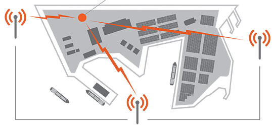
Signal Sentry 1000, an Exelis product that detects and locates GPS interference sources in 3-D by using longitude, latitude and altitude has demonstrated successful results during a planned field testing event held last week at the Vidsel Test Range in Sweden.
Taking advantage of the range’s remote location, Exelis was able to conduct tests of its Signal Sentry 1000 product using controlled jamming. The test was conducted without disrupting the GPS signal relied upon by civilian and military operations outside of the test range location. The test employed eight sensors positioned in an array pattern and showed that Signal Sentry was able to successfully detect and locate the jamming source. Having demonstrating interference detection and location capability, Signal Sentry 1000 can be deployed to collect actionable intelligence for law enforcement and protect GPS signal-dependent critical infrastructures.
Signal Sentry 1000 technology is a network of threat-detection sensors, which is part of a centralized server executing Exelis-developed proprietary location algorithms. These sensors can be strategically located around different types of critical infrastructure, such as shipping ports, utilities and government facilities to automatically sense and locate any intentional or unintentional GPS jamming source. Should a threat be detected, users would receive location information and actionable intelligence in order to determine an interference-mitigation plan.
“Exelis developed Signal Sentry 1000 to help protect critical infrastructure and to deliver intelligence to law enforcement operations that depend upon GPS availability,” said Mark Pisani, vice president and general manager of precision instruments and positioning, navigation and timing for Exelis Geospatial Systems. “Achieving this field test milestone proves that our detection technology works. The next step is to evolve this technology for our military customers.”
Signal Sentry 1000 builds upon Exelis expertise in the field of GPS and positioning, navigation and timing. Exelis payloads and payload components have been on board every GPS satellite for nearly 40 years. Today, Exelis is involved in GPS modernization initiatives, building tomorrow’s GPS III satellite constellation by developing and integrating the navigation payloads. Exelis is also providing navigation processing components, precision monitor station receivers, and key components of the system security design for the GPS Operational Control System, known as OCX.
PCTEL, Inc. announced the launch of its next generation multi-band GNSS antennas for global timing and precision tracking applications at the ION GNSS Conference being held this week in Nashville, Tennessee.
The new antennas, which are designed for use with GPS, GLONASS, BeiDou, and Galileo systems, are being showcased along with other PCTEL antennas at the PCTEL booth in the Exhibit Hall, Booth 318/320. All models of the new antennas are available for sale.
Equipment providers for carrier network timing, precision agriculture, and global asset tracking applications need a single antenna solution for global deployment. PCTEL’s new GNSS1-TMG-26N and GPS-LB12GL-MAG antennas address global compatibility issues for two of the industry’s most crucial applications.
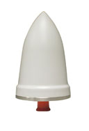
For critical timing applications for macro and small cell deployments, PCTEL has developed the GNSS1-TMG-26N antenna. The GNSS1-TMG-26N is a fixed mount network timing antenna covering GPS, GLONASS, Beidou, and Galileo system frequencies in one single unit, making it a true global solution.
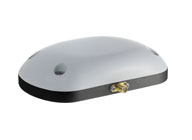
PCTEL’s GPS-LB12GL-MAG antenna is designed for precision agriculture.
For global precision navigation applications, PCTEL has developed the GPS-LB12GL-MAG to cover GPS L1, GPS L2, GLONASS, and L-BAND constellations. The GPS-LB12GL-MAG’s multi-band coverage addresses the precision market in the USA as well as differential correction signals needed across Europe and Asia.
“PCTEL will meet the GNSS market requirements for our global customers while maintaining PCTEL’s high standards for quality and performance,” said Jeff Miller, president of PCTEL Connected Solutions. “We understand that our products need global compatibility to support our customers around the world. We are proud to showcase our design excellence in this highly technical area,” added Miller.
Designed to automatically code and decode GPS signals, encryptors facilitate the exchange of user information by securely transmitting navigation payload data between the OCX ground station and the orbiting constellation of satellites.
“Following successful thermal, electromagnetic interference and security verification testing, Exelis delivered the first three of 14 encryptors,” said Kevin Farrell, positioning, navigation and timing general manager for Exelis Geospatial Systems. “Once integrated into the OCX system, the encryptors will help ensure that the next generation of GPS satellites will be ready for launch and provide advanced capabilities and security to both military and civilian users of the signal and the overall GPS modernization effort.”
Exelis provides critical elements of software in the navigation processing subsystem that will enable controllers to better understand the exact position of GPS satellites. This helps ensure accurate navigation information is securely broadcast to users. In addition to encryptors, Exelis is building high-precision receivers for use in GPS ground monitoring stations and satellite signal simulators for testing purposes.
As part of the overall GPS modernization effort, Exelis is also on contract with Lockheed Martin to provide payloads for GPS III satellites. Exelis is a major space technology provider, supporting both the satellite and ground portions of the GPS III modernization program.
For nearly 40 years, Exelis payloads and payload components have been on board every GPS satellite and have accumulated more than 500 years of on-orbit life without a single mission-related failure due to Exelis equipment.
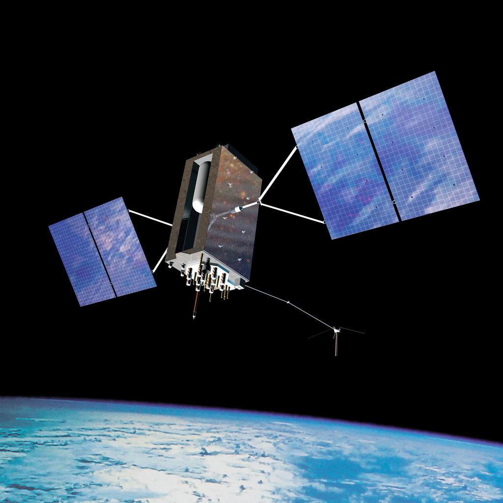
Artist’s concept of the nextgen GPS III satellite (courtesy of the USAF).
Lockheed Martin and Raytheon Company successfully completed the third of five planned launch and early orbit exercises to demonstrate the launch readiness of the world’s most powerful and accurate Global Positioning System (GPS), the U.S. Air Force’s next-generation GPS III satellite and Operational Control System (OCX).
Successful completion of Exercise 3, on August 1, was a key milestone demonstrating Raytheon’s OCX software meets mission requirements and is on track to support the launch of the first GPS III satellite, being produced by Lockheed Martin. Two additional readiness exercises and six 24/7 launch rehearsals are planned before launch of the first GPS III satellite in 2015.
Using new installments of Raytheon’s OCX software and Lockheed Martin’s GPS III Launch and Checkout Capability (LCC), the Air Force Global Positioning System Directorate and the industry team completed a launch and early orbit exercise over a three-day period in late July. Exercise 3 demonstrated space-ground communications; first acquisition and transfer orbit sequences; orbit-raising maneuver planning and execution; and basic anomaly detection and resolution capabilities. In addition, the industry and customer teams jointly executed mission planning activities, such as orbit determination and the generation of upload command files.
Exercise 3 expands on two previous exercises, with a longer mission timeline, and the introduction of simulated vehicle and ground anomalies to evaluate the combined response capabilities of the control segment, satellite and operations crew. “Successful completion of Exercise 3 clearly demonstrates that OCX is on track to support the first GPS III satellite launch,” stated Matt Gilligan, a vice president with Raytheon’s Intelligence, Information and Services business and Raytheon’s GPS OCX program manager. “The system responded as designed, and met all of the launch exercise success criteria and successfully demonstrated our anomaly response.”
“Exercise 3 demonstrated that the cross-organizational operations team is on track to support successful GPS III launch and on-orbit checkout missions from our Newtown facility,” said Keoki Jackson, vice president of Lockheed Martin’s Navigation Systems mission area. “I look forward to the team’s continued success as they progress through the complex mission readiness program towards the first GPS III launch.”
The Lockheed Martin-developed GPS III satellites and Raytheon‘s OCX are critical elements of the U.S. Air Force’s effort to modernize the GPS enterprise more affordably while improving capabilities to meet the evolving demands of military, commercial and civilian users worldwide.
GPS III satellites will deliver three times better accuracy; provide up to eight times more powerful anti-jamming capabilities; and include enhancements which extend spacecraft life 25 percent further than the prior GPS block. The GPS III also will carry a new civil signal designed to be interoperable with other international global navigation satellite systems, enhancing civilian user connectivity. The spacecraft bus and antenna assemblies for the first GPS III satellite have been delivered to Lockheed Martin’s GPS III Processing Facility and are in the integration and test flow leading to the planned space vehicle delivery in mid-2014.
OCX is being developed in two Blocks using a commercial best practice iterative software development process, with seven iterations in Block 1 and one iteration in Block 2. Exercise 3 was conducted using the recently completed Iteration 1.4 software. Exercise 4, scheduled for early 2014, will use Iteration 1.5 software, which includes the Launch and Checkout System capability as well as all critical information assurance features needed to support launch of the first GPS III satellite.
The Geomatics Department at the Oregon Institute of Technology announces that beginning September 30, selected Geomatics courses in Surveying and Geographic Information Systems (GIS) will be offered online. These courses are designed for the working professional that desires formal education to advance in their career. All courses are fully accredited and transferable to the Geomatics degree.
The GIS courses are being taught by John Ritter, and the Surveying courses will be led by Mitch Duryea, PLS. Ritter and Professor Duryea are both faculty at the Oregon Tech campus in Klamath Falls.
Currently recognized as the regional center for excellence for Geomatics in the Northwest and listed as one of the six best Land Surveying schools, Oregon Tech combines theory, problem-solving, and field work in a computer-intensive curriculum that prepares students for employment and licensure as Professional Land Surveyors.
Oregon Tech is the only university in the Northwest to offer a four-year degree in Geomatics that is fully-accredited by the Accreditation Board for Engineering and Technology (ABET). The department offers instruction using state-of-the-art technology, and Oregon Tech Geomatics graduates remain highly sought after by industry. Over 95 percent of students who graduate from Oregon Tech with a Geomatics degree are hired upon or before graduation.
According to the U.S. Bureau of Labor Statistics, the architecture and engineering occupations group which includes surveyors, cartographers, photogrammetrists, and surveying technicians is one of the top 10 occupational groups projected to have the fastest growth in employment between 2002 and 2012. Salary levels are expected to rise as demand for qualified professionals in these fields grows.
“We’re excited to expand our program online,” said Geomatics professor and Professional Land Surveyor, Mitch Duryea. “This offers us even more ability to reach students who are unable to attend our Klamath Falls or Wilsonville campus. At this time, we have 3-4 courses available online each term and have plans to add additional courses in the future.”
For more information about Geomatics online, contact Mitch Duryea, PLS.
The 53rd meeting of the Civil GPS Service Interface Committee will be held Monday and Tuesday, September 16-17, before the Institute of Navigation GNSS+ 2013 Conference. Both events take place at the Nashville Convention Center, in Nashville, Tennessee.
Monday morning’s CGSIC concurrent sessions include the Timing Subcommittee and the Surveying, Mapping, and Geosciences Subcommittee. Monday afternoon’s sessions include the International Information Subcommittee and the U.S. States and Local Government Subcommittee.
Raytheon Company has received Interim Authorization to Test (IATT) security certification for the Global Positioning System Next Generation Operational Control System (GPS OCX) Launch and Checkout System (LCS) four months ahead of schedule.
Raytheon received a one-year certification with no liens, meaning the government does not require any changes. The LCS IATT certification enables Raytheon to move to the next stage of testing the Launch and Checkout System in preparation for launch of the first GPS III satellite.
“Successful IATT certification ahead of our original schedule demonstrates not only that Raytheon meets the U.S. Air Force’s high standards for information assurance as we develop this critical national system, but also the efficient efforts of our government partners,” said Matthew Gilligan, Raytheon’s GPS OCX program manager and a vice president in Raytheon’s Intelligence, Information and Services business. “Typically IATT certification is given for six-month increments; the LCS one-year accreditation speaks to the quality of the information assurance design and threat protection.”
The Interim Authorization to Test not only includes the LCS, but also Lockheed Martin’s GPS III satellite support systems, including the Exercise and Rehearsal Training Tool and Upload Generation Tool.
The next-generation GPS ground-control system, known as OCX.
Raytheon’s OCX and the Lockheed Martin-built GPS III satellites are critical elements of the U.S. Air Force’s effort to modernize the GPS enterprise while improving capabilities to meet the evolving demands of military, commercial and civilian users worldwide. OCX is being developed in two “blocks” using a commercial best-practice iterative software development process. There are seven iterations in Block 1 and one in Block 2. LCS is the fifth Iteration of Block 1, and it successfully completed Critical Design Review in June 2013.
The first GPS III satellite is in production at Lockheed Martin and expected to be delivered to the U.S. Air Force “flight-ready” in mid-2014. GPS III satellites are expected to deliver three times better accuracy, provide up to eight times more powerful anti-jamming capabilities, and include enhancements that extend spacecraft life 25 percent further than the prior GPS block. The GPS III also will carry a new civil signal designed to be interoperable with other international global navigation satellite systems, enhancing civilian user connectivity.
EU Member States have begun their independent testing of the most accurate and secure signal broadcast by the four Galileo navigation satellites in orbit.
Transmitted on two frequency bands with enhanced protection, the Public Regulated Service (PRS) offers a highly accurate positioning and timing service, with access strictly restricted to authorized users.
“Galileo is in its In-Orbit Validation phase, planned to include experimental demonstrations of PRS capabilities in terms of positioning and access control,” explained Miguel Manteiga Bautista, heading ESA’s Galileo Security Office.
PRS access was initially considered for Galileo’s Full Operational Capability phase, but it has been enabled in 2013 in response to the strong interest of Member States in this service. To allow early access to PRS during the current phase, the European Commission and ESA began the joint project ‘PRS Participants To IOV’ (PPTI) in July 2012.
ESA ensured the availability of several tools developed under ESA contracts, including test receivers and other qualification equipment. ESA also provided the critical knowhow and expertise required to conduct these experimental campaigns.
ESA’s PRS Laboratory, based at the Agency’s ESTEC technical centre in Noordwijk, the Netherlands, was used to provide training, demonstrations and sample data.
“As a result, Belgium, France, Italy and the UK have now performed independent PRS acquisition and positioning tests. In parallel, ESA, through collaboration with Dutch and Italian authorities, is also conducting PRS fixed and mobile validation in several locations in the Netherlands and Italy,” added Miguel Manteiga.
The PRS tests have demonstrated a current autonomous positioning accuracy below 10 m when in the correct geometrical configuration. This is an impressive result considering the small number of Galileo satellites in orbit and the limited ground infrastructure so far deployed.
In the case of Italy, which has developed its own PRS receiver, the tests have already confirmed the feasibility of independent PRS receiver development and verification based on specifications provided by the Eurpoean Space Agency (ESA).
ESA’s new Telecommunications and Navigation Testbed Vehicle, a mobile test platform to support test campaigns for navigation and telecommunications services, most notably Europe’s Galileo constellation.
“But the PPTI project is still ongoing in order to test more advanced functionalities this coming autumn and to run the first aeronautical PRS tests in collaboration with the Dutch authorities. Other Member States have also expressed their willingness to join the IOV PRS experimentation campaigns soon,“ concluded Miguel Manteiga.
The project is the first step to ensure the use of the PRS service as soon as it is operational. It will be complemented by the PRS Pilot Projects, focused on PRS applications, which are currently under definition in a common effort between the EU Member States, the European Commission, ESA and the European Global Navigation Satellite System Agency.
In addition to the qualification of the PRS service, these initiatives will allow the timely availability of competitive PRS receivers in Europe and the setting up of organizations in the Member States required to handle PRS, ESA said.
In the field, capture up to 200 MHz of multi-channel bandwidth and return to your lab with a rich library of GPS and GLONASS signals and impairments to accelerate RF product designs and research. Add a camera for a complete view and map of your recording environment.
Averna’s RF Studio software and suite of award-winning RF test instruments set the standard for portability, flexibility and repeatability, empowering you to efficiently record and play back all common radio, video, and GNSS signals in the highest fidelity to accelerate RF projects and reduce travel and testing costs.
RF Studio: A Powerful Software for Easy RF Recording
Available with Averna’s RF recorders and for National Instruments’ USRP, the versatile RF Studio features signal templates for quick setup and recording. With the Noise Figure feature you can view and record weak signals under the noise floor, and with the Spectrum, Power, and Histogram views you can visualize and analyze all your captured RF spectrum.
With the optional DriveView™ module, you can capture a complete visual record and map of where you made your recordings to aid analysis and troubleshooting. As well, RF Studio’s plug-in architecture supports additional hardware, channels, user inputs, remote triggering and a distributed control interface to ensure the widest possible application.
RF Studio is available with the following platforms
National Instruments’ USRP
RF Studio for the USRP is the only product on the market in its price range that offers the flexibility to cover a wide variety of use cases, thus making it a very competitive solution for general-purpose RF R&P. RF Studio gives NI USRP customers a turnkey RF R&P solution while also leveraging the flexibility and customization possibilities that have made this software-defined radio such a successful platform.
Averna’s RF Record & Playback Solutions
Our suite of RF test instruments sets the standard for portability, flexibility and repeatability, empowering RF device manufacturers to efficiently generate, record and play back all common radio, video, and navigation signals, ensuring complete test coverage and the highest quality for their RF products.
Multi-Channel, 50 MHz and 20 MHz Compact RF Recorders
By Richard Langley, Steffen Thoelert, and Michael Meurer
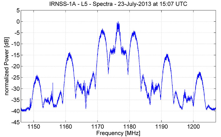
The spectrum of signals from IRNSS-1A, the first satellite in the Indian Regional Navigation Satellite System, as recorded by German Aerospace Center researchers in late July, appears to be consistent with a combination of BPSK(1) and BOC(5,2) modulation.
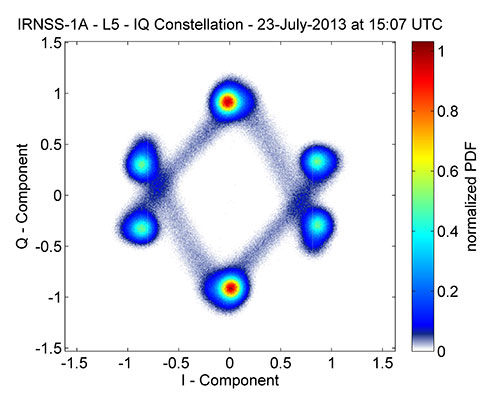
Figure 1 shows that, centered at 1176.45 MHz, the signal has a single symmetrical main lobe and a number of side lobes characteristic of the signal structure that the Indian Space Research Organization (ISRO) announced would be used for IRNSS transmissions in the L-band. Figure 2 shows the corresponding IQ constellation diagram. Further analysis will be required to sleuth additional signal details as ISRO, so far, has not publicly released an IRNSS interface control document describing the signal structure in detail.
Figure 1. Spectrum of IRNSS-1A L5 signal.Figure 2. IQ constellation diagram of IRNSS-1A L5 signal.
The German scientists caution that “this is a very early snapshot of the current signal transmission and probably both the signal power and the signal quality will change and possibly improve during the in-orbit-testing phase of the satellite’s operation.
Extra Life for IIRs, IIR-Ms
U.S. Air Force engineers are testing on-orbit a technique to extend the life of the 19 GPS IIR and IIR-M satellites on orbit, roughly 60 percent of the current contellation.
A new charging method may reduce the rate of satellite battery degradation, thereby extending satellite operational life. If the technique passes the test, the initiative could add a combined 20 years to the life of the satellites — saving the Air Force tens of millions of dollars in the process.
Gen. William Shelton, commander of Air Force Space Command, credits Capt. Jacob Hempen of the Air Force’s 2nd Space Operations Squadron for the job. Capt. Hempen says in turn that Warren Hwang of the Aerospace Corporation originated the idea.
When satellite solar panels are directly exposed to the Sun, they charge satellite batteries while continuing to power other operations onboard the space vehicle. When the satellite passes into the Sun’s shadow behind the Earth, it runs on batteries. The batteries can be re- charged at variable rates. When some of the batteries are powered above a certain rate threshold, they can overheat, accelerating their natural rate of decay.
Lowering battery charging rates could still enable the satellites to perform well while minimizing the rate of degradation. Hitting the optimum number called for some finely-honed calculations.
The satellites were built by Lockheed Martin Space Systems, and the oldest still in operation was launched in 1997.
They had an intial design life of eight years, which many have now well outlasted. If the technique proves out and is carefully applied across the board, it could conceivably fill in replenishment gaps equivalent more than two additional spacecraft — conceivably as much hundreds of millions of dollars in build and launch costs, postponed. In today’s budget environment, a postponement can be construed as equivalent to outright savings.
System Briefs
GLONASS Partial Make-Good. Russia will launch two GLONASS satellites later this year to make up for the loss of three satellites in the July 2 Proton rocket explosion. The first is scheduled for the beginning of September, and the second at the end of October. Both will rise aboard Soyuz carrier rockets, which have proven more reliable than the Protons. A constellation of 29 GLONASS satellites is now in orbit, with 24 spacecraft in operation, three spares, one in maintenance, and one in test flight phase.
Meanwhile, plans to reduce GLONASS funding have alarmed at least some deputies of the Duma, the Russian state legislative body. Government officials have floated a plan to reduce funding of the space program in 2014 by 11.7 billion rubles ($355 million), by 13.5 billion rubles in 2015, and by 40 billion rubles in 2016. The federal space program of Russia for 2006-2015 already lacks 10.5 billion rubles funding, and this year there has been a 2.3-billion-ruble additional reduction in R&D. A Duma committee chairperson warned that this trend will “lead to the loss of confidence of the international community in the GLONASS system and, consequently, to a reduction in its use globally. Russia will lose a strategic global instrument of political and economic prestige.” The Duma has recommended that the government maintain funding of federal space programs.
Galileo Satellites’ Trial By Noise. The first Galileo Full Operational Capability (FOC) satellite successfully completed acoustic testing in July, part of a full-scale test campaign at ESA’s ESTEC Test Centre in Noordwijk, the Netherlands.
The satellite was placed in the Large European Acoustic Facility (LEAF), effectively the largest sound system in Europe. A quartet of noise horns embedded in a wall of the 11 x 9 x 16.4 meter test chamber generated an acoustic noise level of 140.7 decibels, about the same noise as standing 25 meters from a jet taking off, and intended to simulate the extreme environment experienced by a satellite atop a rocket about to fire itself off the launch pad.
A second FOC satellite arrived at ESTEC on 9 August from manufacturer OHB in Bremen, Germany. It will undergo a similar acoustic testing and then a System Compatibility Test Campaign will linking it with the Galileo Control Centres in Germany and Italy and ground user receivers as if it were already in orbit.
A total of 14 FOC satellites are being produced and then tested at ESTEC as an integral part of their path to orbit. A second work order of eight satellites has been given to OHB.
GPS III Pathfinder. On July 19, Lockheed Martin delivered a full-sized, functional prototype of the next-generation GPS satellite to Cape Canaveral Air Force Station to test facilities and pre-launch processes in advance of the arrival of the first GPS III flight satellite.
The GPS III Non-Flight Satellite Testbed (GNST) paves the way for the first flight GPS III satellite, expected to arrive at the Cape in 2014, ready for launch by in 2015.
An innovative investment by the Air Force under the original GPS III development contract, the GNST has helped to identify and resolve development issues prior to integration and test of the first GPS III flight space vehicle (SV-01).
Following the Air Force’s rigorous “back-to-basics” acquisition approach, the GNST has gone through the development, test and production process for the GPS III program first, significantly reducing risk for the flight vehicles, improving production predictability, increasing mission assurance and lowering overall program costs.
Lockheed Martin is currently under contract for production of the first four GPS III satellites (SV 01–04), and has received advanced procurement funding for long-lead components for the fifth, sixth, seventh and eighth satellites (SV 05–08).
GNSS Industry Survey. Here are the results of two questions asked about government and industry from the 2013 GNSS STATE OF THE INDUSTRY SURVEY.
Is government committed to private industry in a time of drastic budget cuts?Is industry actively making its concerns known to government?
By Steffen Thoelert, Johann Furthner, and Michael Meurer
Future positioning and navigation applications of modernizing and newly established GNSSs will require a higher degree of signal accuracy and precision. Thus, rigorous and detailed analysis of the signal quality of recently launched satellites, including the discovery of any possible imperfections in their performance, will have important implications for future users.
Global navigation satellite systems achieved amazing progress in 2012, with major milestones reached by the various navigation and augmentation systems, bringing new satellites and satellite generations into orbit. Since the complexity of the satellites and also the requirements for a precise and robust navigation increase consistently, all of the newly available signals of the existing or emerging navigation satellite systems must be analyzed in detail to characterize their performance and imperfections, as well as to predict possible consequences for user receivers.
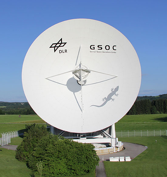
Since the signals are well below the noise floor, we use a specifically developed GNSS monitoring facility to characterize the signals. The core element of this monitoring facility is a 30-meter high-gain antenna at the German Aerospace Center (DLR) in Weilheim that raises GNSS signals well above the noise floor, permitting detailed analysis. In the course of this analysis, we found differences in the signal quality in the various generations of the Chinese navigation satellite system BeiDou, differences which influence the navigation performance.
This article gives an overview of new navigation satellites in orbit. For selected satellites, a first signal analysis reveals important characteristics of these signals. The data acquisition of these space vehicles was performed shortly after the start of their signal transmission to get a first hint about the quality and behavior of the satellites.
For more detailed analysis, these measurements should be repeated after the satellites become operational. Then the acquired high-gain antenna raw data in combination with a precise calibration could be used for a wider range of analyses: signal power, spectra, constellation diagrams, sample analysis, correlation functions, and codes to detect anomalies and assess the signal quality and consequently the impact at the user performance.
Measurement Facility
In the early 1970s, DLR built a 30-meter dish (Figure 1) for the HELIOS-A/B satellite mission at the DLR site Weilheim. These satellite missions were the first U.S./German interplanetary project. The two German-built space probes, HELIOS 1 (December 1974–March 1986) and HELIOS 2 (January 1976–January 1981), approached the Sun closer than the planet Mercury and closer than any space probe ever. Later, the antenna supported space missions Giotto, AMPTE, Equator-S, and other scientific experiments.
Figure 1. 30-meter high-gain antenna.
In 2005, the Institute of Communications and Navigation of the DLR established an independent monitoring station for analysis of GNSS signals. The 30-meter antenna was adapted with a newly developed broadband circular polarized feed. During preparation for the GIOVE-B in-orbit validation campaign in 2008, a new receiving chain including a new calibration system was installed at the antenna. Based on successful campaigns and new satellite of modernizing GPS and GLONASS, and GNSSs under construction — Galileo and COMPASS — the facility was renewed and updated again in 2011/2012.
This renewal included not only an upgrade of the measurement system itself, but also refurbishment of parts of the high-gain antenna were refurbished.
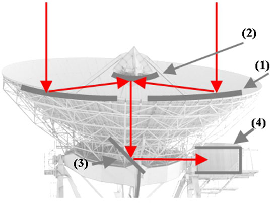
The antenna is a shaped Cassegrain system with an elevation over azimuth mount. The antenna has a parabolic reflector of 30 meters in diameter and a hyperbolic sub-reflector with a diameter of 4 meters. A significant benefit of this antenna is the direct access to the feed, which is located within an adjacent cabin (Figure 2). The L-band gain of this high-gain antenna is around 50 dB, the beam width is less than 0.5°. The position accuracy in azimuth and elevation direction is 0.001°. The maximum rotational speed of the whole antenna is 1.5°/second in azimuth and 1.0°/second in elevation direction.
Figure 2. The shaped Cassegrain system: (1) parabolic reflector of 30 m diameter; (2) hyperbolic sub- reflector with a diameter of 4 meter; (3) sub-reflector; (4) Cabin with feeder and measurement equipment.
Measurement Set-up
The antenna offers another significant advantage in the possibility to have very short electrical and high-frequency connection between the L-band feeder and the measurement equipment. As mentioned earlier, the challenge for future GNSS applications is the high accuracy of the navigation solution. Therefore, it is necessary to measure and then analyze the signals very accurately and precisely. To achieve an uncertainty of less than 1 dB for the measurement results required a complete redesign of the setup, which consists of two main parts:
paths for signal receiving and acquiring the measurement data;
calibration elements for different calibration issues.
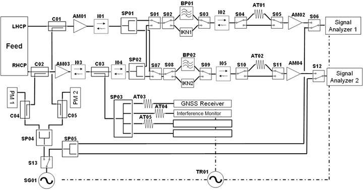
The path for receiving the signal and acquiring the measurement data consists of two signal chains, each equipped with two low-noise amplifiers (LNAs) with a total gain of around 70 dB, a set of filters for the individual GNSS navigation frequency bands, and isolators to suppress reflections in the measurement system. With this setup it is possible to measure right-hand circular polarized (RHCP) and left-hand circular polarized (LHCP) signals in parallel.
This provides the capability to perform axial ratio analysis of the satellite signal, and consequently an assessment of the antenna of the satellite. Using the switches SP01 and SP02, the measurement system is also able to acquire data from two different bands at the same time. This enabless investigations concerning the coherence between the signals in post-processing.
The signals are measured and recorded using two real-time vector signal analyzers with up to 120 MHz signal bandwidth. Both analyzers are connected to a computer capable of post-processing and storing the data. Additional equipment like digitizers or receivers can be connected to the system using the splitter III outputs, where the unfiltered RHCP signals are coupled out after the first LNA. A high-performance rubidium clock is used as reference signal for the whole measurement equipment. In front of the first LNA of each chain, a signal can be coupled in for calibration issues.
Control Software. Due to the distance of the antenna location from the Institute at Oberpfaffenhofen (around 40 kilometers) it was necessary to perform all measurement and calibration procedures during a measurement campaign via remote control. A software tool was developed which can control any component of the setup remotely. In addition, this software can perform a complete autonomous operation of the whole system by a free pre-definable sequence over any period of time. This includes, for example, the selection of the different band-pass filters, the polarization output of the feed, and the control of the calibration routines.
After the measurement sequence, the system automatically copies all data via LAN onto the processing facility, starts basic analysis based on spectral data, and generates a report. Sophisticated analysis based on IQ raw data is performed manually at this time.
Absolute Calibration
To fulfill the challenge of highly accurate measurements, it is necessary to completely characterize all elements of the measurement system, which comprises the antenna itself and the measurement system within the cabin after the feed. An absolutely necessary precondition of the calibration of the high-gain antenna is a very accurate pointing capability. The pointing error should be less than 0.01° concerning antennas of this diameter.
Furthermore, it is important to check long-term stability of these characterizations and the influences of different interference types and other possible error sources. This has to be taken in to account, when it comes to a point where the value of the absolute calibration has the same range as the summed measurement uncertainties of the equipment in use.
Antenna Calibration. High-accuracy measurements require not only the correct antenna alignment but also accurate power calibration of the antenna. To determine the antenna gain, well known reference sources are needed. These could be natural sources like radio stars or artificial sources like geostationary satellites.
Standard reference signal sources for the calibration of high-gain antennas are the radio sources Cassiopeia A, Cygnus, and Taurus. All these radio sources are circumpolar relative to our ground station, and therefore usable for calibrations at all times of the year. A further advantage of these calibration sources is the wide frequency range of the emitted signals. Thus, contrary to other signal sources (like ARTEMIS satellite L band pilot signal) the antenna gain can be calibrated in a wide bandwidth. With the help of the well-known flux density of the celestial radio sources and using the Y-method, the relation between the gain of the antenna and the noise temperature of the receiving system, or G/T, can be measured. Measuring the noise figure of the receiving system, the antenna gain can finally be calculated.
System Calibration. The measurement system calibration behind the feed is performed using wideband chirp signals. The chirp is injected into the signal chains via coupler I and II (Figure 3). The calibration signal is captured by the two vector signal analyzers. In the next step, the signal is linked via the switches directly to the analyzers, and the chirp signals are recorded as reference again. It has to be taken into account that more elements are in the loop during the chirp recordings compared to the receiving chain. These are the link between the signal generator and the couplers and the direct path to the analyzers.
Figure 3. Measurement setup overview.
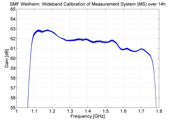
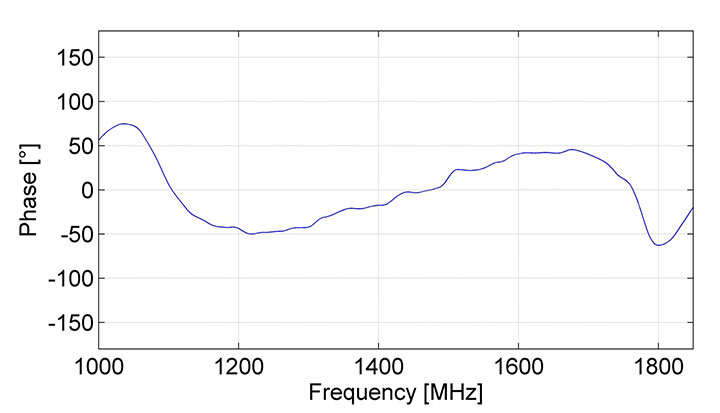
To separate the receiving chain from the additional elements within the wideband calibration loop, two more measurements are needed. The injection path from the signal generator to the couplers and the direct paths are characterized by network analyzer (NWA) measurements. Based on the chirp and NWA measurements, the transfer function of the system is calculated to derive the gain and phase information. To determine the calibration curve over the frequency range from 1.0 GHz to 1.8 GHz, a set of overlaying chirps with different center frequencies is injected into the signal paths and combined within the analysis. Figure 4 and Figure 5 show the results of the wideband calibration of gain and phase.
Figure 4. Gain of the measurement system after the feed over 14 hours.Figure 5. Phase of measurement system.
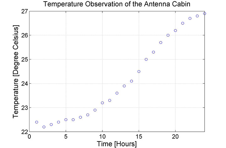
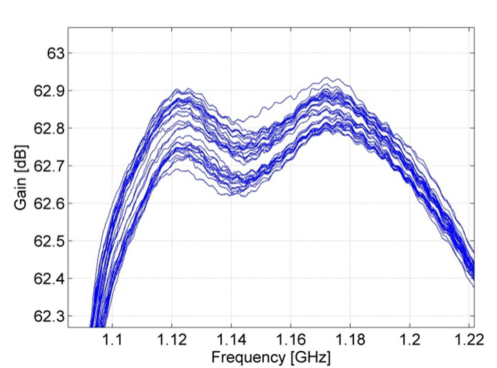
Is it enough to determine the gain only once? If we assume that there is no aging effect of the elements, and the ambient conditions like temperature are constant, the gain should not change. In reality the behavior of the system is not constant. Figure 6 shows the temperature within the cabin during a failure of its air conditioning system. Figure 7 shows the corresponding gain of the measurement system during the temperature change in the cabin of about 5° Celsius. Clearly, it can be seen that the gain changed around 0.2 dB.
Figure 6. Cabin temperature increase during outage of the air condition concerning measurements shown in Figure 7.Figure 7. Gain variations of the measurement system based on temperature variations in the cabin (see Figure 6).
This example shows the sensitivity of the system to changes in environmental conditions. Usually the measurement system is temperature-stabilized and controlled, and the system will not change during data acquisition. But every control system can be broken, or an element changes its behavior. For this reason, the calibration is performed at least at the beginning and at the end of a satellite path (maximum 8 hours).
Measurement Results
Here we present selected results from the European Galileo and the Chinese BeiDou navigation systems.
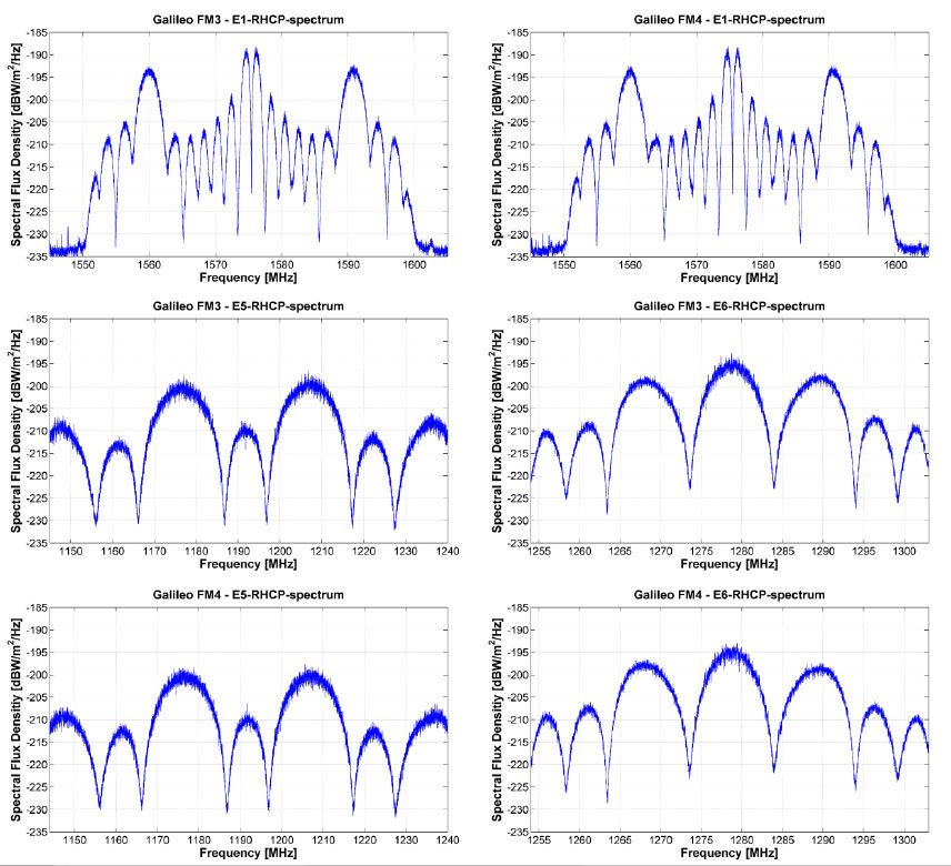
Galileo FM3 and FM4. In October 2012, the third and fourth operational Galileo satellites, FM3 and FM4, were launched into orbit. Signal transmissions started in November and in December, respectively. Both satellites provide fully operational signals on all three frequency bands, E1, E5, and E6. The measurement data of both satellites were captured in December 2012, shortly after the beginning of the signal transmission. Figure 8 shows the spectra of both satellites for El, E5, and E6 bands. The quality of the transmitted signals seems to be good, but for the El signal of FM4 satellite, minor deformations of the spectra are visible.
Figure 8. Measurement results of Galileo IOV FM3 & FM4: El, E5 and E6 spectra.
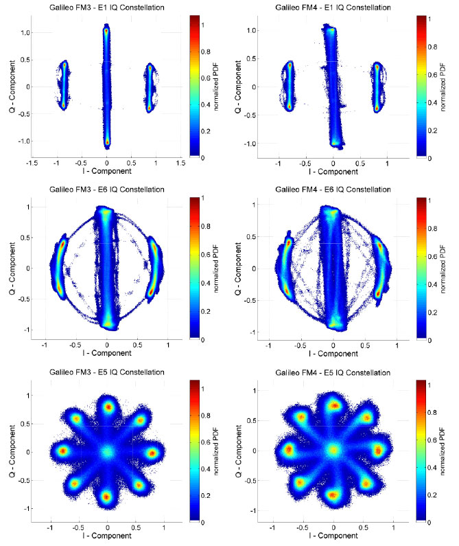
Figure 9 shows the results of the IQ constellations both for FM3 and FM4 concerning each transmitted signal band. The constellations and consequently the modulation quality of each signal are nearly perfect for the FM3 satellite. The IQ constellation diagrams of FM4 show minor deformations in each band. What impact these imperfections create for future users has yet to be analyzed. Both satellites were at the time of measurement campaign still in the in-orbit test phase and did not transmit the final CBOC signal in the E1 band. It could be expected that especially the signals of the FM4 will be adjusted to become more perfect.
Figure 9 Measurement results of Galileo IOV FM3 & FM4: E1, E5, and E6 – IQ Constellation.
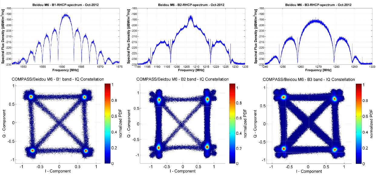
BeiDou M6. BeiDou satellites transmit navigation signals in three different frequency bands, all are located adjacent to or even inside currently employed GPS or Galileo frequency bands. The center frequencies are for the B1 band 1561.1 MHz, B3 band 1268.52 MHz, and B2 band 1207.14 MHz.
In 2012, China launched six satellites: two inclined geostationary space vehicles and four medium-Earth orbit ones, concluding in September (M5 and M6) and October 2012 (IGSO6). There have been further BeiDou launches in 2013, but these satellites’ signals are not analyzed here.
Figure 10 displays calibrated measurement results from the Beidou M6 satellite. The spectra of the B2 and B3 band of the Beidou M6 satellite are clean and show no major deformation. Within the B1 spectra, some spurious results, especially on top of the side lobes, are obvious. This behavior has to be investigated more in detail to determine their origin. The IQ diagrams, which visualize the modulation quality, show also no major deformation. Only within the B3 signal, a marginal compression of the constellation points can be seen, which points to a large-signal operation at the beginning of the saturation of the amplifier of the satellite.
Figure 10. BeiDou M6 satellite signal spectra and IQ constellations at B1, B2 and B3 band
Conclusion
Reviewing the quality of the presented measurements, signal analysis, and verification on GNSS satellites, the use of the 30-meter high-gain antenna offers excellent possibilities and results. Regarding the calibration measurements of the antenna gain and measurement system, the variances are in the range of measurement uncertainty of the equipment.
The sensitivity of the measurement system concerning ambient conditions was exemplarily shown based on the gain drift caused by a temperature drift. But the solution is simple: stabilize the ambient conditions or perform calibration in a short regular cycle to detect changes within the system behavior to be able to correct them.
Based on this absolute calibration, a first impression of the signal quality of Galileo FM3 and FM4 and the BeiDou M6 satellites were presented using spectral plots and IQ diagrams. Only minor distortion could be detected within the Galileo FM4 and Beidou M6 signal; these distortions may be negligible for most users. Concerning FM4 and FM3, both satellites were in the in-orbit test phase during the data acquisition. The signal quality may have been changed during their stabilization process in orbit, or the signals have been adjusted in the meantime. Thus, it would be interesting and worthwhile to repeat the measurements and perform detailed analysis to assess the final satellite quality and consequently the user performance.
Acknowledgments
The authors wish to thank the German Space Operation Centre for the opportunity to use the high-gain antenna. The support of colleagues at the DLR ground station Weilheim for the operational and maintenance service over recent years is highly appreciated. This work was partly performed within the project “Galileo SEIOT (50 NA 1005)” of the German Space Agency, funded by the Federal Ministry of Economics and Technology and based on a resolution by the German Bundestag. Finally, the support of DLR’s Centre of Excellence for Satellite Navigation is highly appreciated.
This article is based on the paper “GNSS Survey – Signal Quality Assessment of the Latest GNSS Satellites” presented at The Institute of Navigation International Technical Meeting 2013, held in San Diego, California, January 28–30, 2013.
Steffen Thoelert received his diploma degree in electrical engineering at the University of Magdeburg. He works in the Department of Navigation at German Aerospace Centre (DLR), on signal quality assessment, calibration, and automation of technical processes.
Johann Furthner received his Ph.D. in laser physics at the University of Regensburg. He works in the DLR Institute of Communication and Navigation on the development of navigation systems in a number of areas (systems simulation, timing aspects, GNSS analysis, signal verification, calibration processes).
Michael Meurer received a Ph.D. in electrical engineering from the University of Kaiserslautern, where he is now an associate professor, as well as director of the Department of Navigation at DLR.
U.S. Air Force engineers are testing on-orbit a technique to extend the life of the 19 GPS IIR and IIR-M satellites on orbit, roughly 60 percent of the current constellation.
A new charging method may reduce the rate of satellite battery degradation, thereby extending satellite operational life. If the technique passes the test, the initiative could add a combined 20 years to the life of the satellites — saving the Air Force tens of millions of dollars in the process.
Gen. William Shelton, commander of Air Force Space Command, credits Capt. Jacob Hempen of the Air Force’s 2nd Space Operations Squadron for the job. Capt. Hempen says in turn that Warren Hwang of the Aerospace Corporation originated the idea.
When satellite solar panels are directly exposed to the Sun, they charge satellite batteries while continuing to power other operations on board the space vehicle. When the satellite passes into the Sun’s shadow behind the Earth, it runs on batteries. The batteries can be recharged at variable rates. When some of the batteries are powered above a certain rate threshold, they can overheat, accelerating their natural rate of decay.
Lowering battery charging rates could still enable the satellites to perform well while minimizing the rate of degradation. Hitting the optimum number called for some finely-honed calculations.
The satellites were built by Lockheed Martin Space Systems, and the oldest still in operation was launched in 1997. They had an initial design life of eight years, which many have now well outlasted. If the technique proves out and is carefully applied across the board, it could conceivably fill in replenishment gaps equivalent more than two additional spacecraft — conceivably as much hundreds of millions of dollars in build and launch costs, postponed. In today’s budget environment, a postponement can be construed as equivalent to outright savings.