James D. Litton, President/CEO, Litton Consulting Group
Precise positioning of many different kinds of vessels and other equipment depend upon satellite-based augmentation systems (SBAS) of GNSS, principally GPS and GLONASS at this time. The applications range from exploration to production and delivery of hydrocarbons to shore-based installations and navigation of very large crude carriers, or oil tankers. Decisions and recommendations are strongly needed to keep these services free from interference.
It is fallacious to think that because LightSquared or similar use of out-of-band high-power terrestrial radiation would be confined to a continental region (physically impossible, in any case), that no harm would accrue to offshore navigation assets. The three principal suppliers of these offshore precise positioning services are Fugro’s Starfix services, C&C Technology’s C-Nav which utilizes John Deere/NavCom’s StarFire systems, and Subsea 7’s Veripos system.
All of these systems depend upon GNSS reference receivers placed around the world in networks which depend upon corrections that are derived from regionally sited reference stations. The 10-centimeter level of precision now required for many of the most dangerous and valuable applications requires, in turn, centimeter-level accuracy in base stations in the United States and elsewhere in the world.
Inmarsat frequencies allocated to these applications for delivery of the differential corrections generated by these reference stations have been in use for both the huge number of land applications (agriculture, infrastructure development, river and harbor navigation, seismic exploration, pipeline surveys, etc) and offshore applications. Changing these frequencies is feasible only at great cost to both Inmarsat and the many on- and offshore uses. Inmarsat may be compensated by LightSquared for its costs, but not so the many millions of dollars of expense to offshore and onshore operators in down time, redesign and reprogramming of receivers, and suspension of critical operations.
The offshore applications outlined here are just a few of the more familiar. No attempt has been made to capture all of these applications in this short memorandum, but operators in this industry, represented by the National Ocean Industries Association (NOIA), have made their position clear in the attached letter to the FCC.
Major Offshore Applications
Exploration. Modern seismic exploration depends upon seismic streamers many kilometers long. Several such streamers (containing thousands of hydrophones for capturing reflections from deep beneath the ocean floor and determining the structure and composition of the strata which may contain hydrocarbons) are towed by each ship. The seismic profiles which result are depicted in three dimensions with great precision. Discovery and assessment of such strata depend sensitively upon the positioning accuracy of these streamers, which, in turn, depend sensitively on the position of the vessel with respect to the center of the earth, because the vessel’s trajectory is the reference for the relative positioning of the streamers by magnetic and inertial means, sometimes augmented by GNSS receivers integrated into the seismic streamers.
Drilling. Increasingly, drill rigs and drill ships are placed and maintained in position by dynamic positioning systems that depend upon augmented GNSS systems for stabilizing the massive structures over the well head. In deep water (more than 5,000 feet), only dynamic positioning through the use of massive thrusters (such as those employed by the Deepwater Horizon vessel of Transocean in the Macondo well disaster, commonly referred to as the BP disaster) is feasible. With as much as 10,000 feet of riser attached to these drill ships between the well head and the ship, safe operation is critically dependent upon very precise positioning of the vessel. Further, down-hole positioning depends upon inertial and wireline systems, which are calibrated by the use of augmented GNSS systems.
Production. Production platforms range from single sites over a single well to massive platforms with undersea pipelines and risers connecting them to manifolds on the sea floor, which in turn are connected to multiple well heads in an area. This infrastructure is placed, maintained, and monitored with the use of SBAS systems integrated with acoustic systems. Use of remotely operated vehicles and autonomous underwater vessels or vehicles, submarines equipped with sensors that can image and manipulate underwater structures, for these purposes is prevalent.
Station Keeping. Supply vessels, crew vessels, special-purpose vessels, and helicopters are positioned relative to the drill rig, seismic vessel, production platform, and pipeline-laying vessel by SBAS systems fused with other sensors such as lasers and microwave distance-measuring equipment. A huge drill ship, for instance, moving about in response to ocean dynamics but centered on the well head, cannot be docked to a supply vessel solely with ropes and cables. Each vessel must be free to move but to move synchronously with each other. Because of the huge masses involved, the velocity of each relative to the other must be kept as near zero as possible. Centimeter-level precision is required for this purpose. In all of the applications listed above, at various stages, vessels require station keeping with other vessels to very precise relative distances and velocities.
Containment and Recovery. When there is a requirement for a flotilla of vessels such as attended the Macondo blow-out event, there are as many as a hundred large and small vessels in a relatively small area, with the need for central control (by the U.S. Coast Gaurd in this case) and collision-avoidance systems. These systems also depend upon having precise GNSS, mostly using SBAS systems.
Further application details and additional critical applications can be provided upon request.
Jim Litton is the President of the Litton Consulting Group, Inc. (LCG). His GPS-related experience includes being the Chief Engineer at Magnavox during the GPS phase I development, contributing to analysis of ionospheric effects and senior vice-president and general manager of the Magnavox Commercial GPS Division before forming the Litton Consulting Group in 1992. He co-founded NavCom Technology in 1994. He holds the Hays award from the ION for 1996 and is co-inventor on a codeless GPS receiver patent.
Recent events, some of them summarized here, may appear to have dealt setbacks to LightSquared, the boundless opportunist of wireless broadband that just happens to interfere with GPS. But the company has not run out of moves yet. Would you, if you had $20 billion at stake? The latest gambit, led by lawyers and cloaked in jargon, appears to be an end-run around the U.S. government to appeal to the International Telecommunications Union, which has ultimate and international authority over spectrum. Watch out, GLONASS and Galileo — and U.S. troops operating in foreign theaters.
GPS World has received copies of three “fact sheets” authored by two lawyers and a strategic consultant. The documents are addressed to ITU-R WP 4C, the International Telecommunications Union Working Party that handles mobile satellite services (MSS) and radio determination satellite service (RDSS spectrum) and orbits. One document is titled “ Compatibility between Complimentary Ground Componenet in the 1525–1559 Mhz and 1626.5–1660.5 Mhz Bands and Other Service.” All three documents appear to be cover sheets for longer treatises, and their language and citations are not entirely clear to me, as my legal and regulatory background leaves something to be desired.
However, they announce their purpose as “to modify and refine the example methodology to calculate aeronautical mobile satellite (route) service spectrum requirements,” and “to address ongoing Integrated Mobile Satellite Service Complimentary Ground Component compatibility matters,” and finally “to update the Integrated Mobile Satellite Service Complimentary Ground Component technical characteristics based upon the most recent information regarding CGC deployment plans in this frequency band.”
One source familiar with the documents, who did not wish to be named, commented that “One should interpret what LightSquared is doing with ITU as a bellwether indication of intent to use the whole band at the full authorized power, no matter how they spin ‘protect GPS’ in their press releases.
“At first blush, the filings look innocuous; let me assure you, they are not. This is the first salvo. Watch what they do, much more than what they say.
“These are fact sheets intended to inform the U.S. government that LightSquared intends to develop papers with the intent to get the U.S. government to approve the papers to be sent to the ITU WP-4C, the Working Party that handles MSS and RDSS spectrum & orbits. The ultimate goal is to work internationally to allow LightSquared to allow ancillary terrestrial component (ATC) broadcast globally.”
In other developments, going now in reverse chronological order, from most recent to early June:
Congressional Activity
On June 23, the U.S. House of RepresentativesAppropriations Committee approved the fiscal year 2012 Financial Services and General Government Appropriations bill. One amendment to the bill prohibits funding for the Federal Communications Commission (FCC) to remove conditions on or permit certain commercial broadband operations until the FCC has resolved concerns of harmful interference by these operations on GPS devices. The amendment was adopted on a voice vote. More details here.
Previously, on May 27, the U.S. House of Representatives passed a bill stating that the FCC shall not provide final authorization for LightSquared operations until Defense Department concerns about GPS interference have been resolved. The bill then went to the U.S. Senate for its action.
The House actions and a letter to the FCC signed by 32 U.S. senators may presage a showdown over the issue between Congress and the president, who has promised increased broadband access. A 4G wireless network providing this access could be facilitated by LightSquared sales of service via its tower transmitters to wireless carriers. LightSquared has already signed a $20 billion, 15-year deal with Sprint.
Money Talks
A report on “The Economic Benefits of Commercial GPS Use in the United States and the Costs of Potential Disruption” was presented by during a June 21 webinar sponsored by the Coalition to Save Our GPS. The report estimates that “the direct economic benefits of GPS technology on commercial GPS users are . . . over $67.6 billion per year in the United States,” but also that ““the direct economic costs of full GPS disruption to commercial GPS users and GPS manufacturers are estimated to be $96 billion per year in the United States.” Final Report Withheld
At the last minute of a June 15 deadline for the final Working Group report on interference, LightSquared asked for a two-week extension. Federal regulators granted the request, and the final report is now due on July 1.
A spokesperson for the Coalition to Save Our GPS revealed that “The Working Group results show devastating interference to GPS and no proven method of mitigation. Delay will not change these results. These results are the same results the FCC had had before it granted the waiver.”
Some Solution. Three days after requesting the delay, LightSquared announced it had solved the problem, by proposing to broadcast only from the lower end of its permitted spectrum band. GPS experts countered that this would still disable the functioning of high-precision receivers.
“This comes out of the blue, without the knowledge, agreement or consensus of the industry group studying the problem,” riposted the Coalition to Save Our GPS. “That may well be because virtually nothing has actually changed in this “new” proposal relative to what LIghtSquared pledged at the outset of testing. The power levels don’t change. Nor do the frequencies. In fact, the only thing that has changed is the order in which the channels within the band adjacent to GPS would be deployed.
“LightSquared’s announced “solution” has two components:
“1. LightSquared acknowledges that “[e]arly test results indicated that one of LightSquared’s 10MHz blocks of frequencies poses interference to many GPS receivers.” LightSquared states that for “the next several years” it would not operate in this band – which is directly adjacent to GPS spectrum and is referred to as the “upper MSS band.” During this period, LightSquared would commence operations in a second 10 MHz block of the MSS band , referred to as the “lower MSS band,” slightly further away from GPS.
“2. According to the proposal ‘LightSquared will modify its FCC license to reduce the maximum authorized power of its base-station transmitters by over 50 percent. This action will limit LightSquared to the power it was authorized to use in 2005.’
“This so-called solution is not a solution in any shape, form or fashion,” continues the Coalition. “This is not a move to an alternative frequency band. Nor is it a reduction in power relative to what has been tested from the beginning. The “solution” would cause massive disruption to many critical U.S. economic sectors, initially including public sector users of high precision GPS, later followed – af
ter “the next several years” — by other GPS users. The only real solution to the LightSquared interference problem is to move out of the MSS band altogether."
The Air Transport Association and the Aircraft Owners & Pilots Association told Congress that the only acceptable mitigation is for LightSquared’s operations to be moved outside of the L-band and away from GPS. “With so much of the early evidence showing that LightSquared’s proposed network would potentially endanger nearly every flight operating in U.S. airspace, it seems evident that no further development of this system can be allowed.”
Military Report Calls for FCC Retreat
The National PNT Engineering Forum concluded after testing classified and GPS receivers under LightSquared terrestrial transmission conditions: “Significant concerns remain that operation of an ATC integrated service as originally envisioned by the FCC cannot successfully coexist with GPS.”
The NPEF report calls for rescinding the FCC waiver for LightSquared terrestrial transmissions, conducting more thorough studies on impacts, and revisiting the 2003–2010 authorizations. The group tested a variety of military receivers under classified categorization, also known as “government receivers.” Rebuttals Distort Record
Claims by LightSquared’s Carlisle and FCC chair Julius Genachowski, that the GPS industry knew long ago about LightSquared’s plan for powerful terrestrial transmitters, contradict the truth. Examination of FCC filings show that the GPS industry knew about and agreed to a plan by a previous ownership of the company, for a different purpose, with a different business concept, and employing a completely different technological approach, one that would not have harmed GPS transmissions and disabled GPS users the way the current LightSquared plan does.
The terrestrial broadband operations first unveiled in November 2010 cannot be described as ancillary to the purpose for which Lightsquared predecessors Motient, MSV, and SkyTerra received their spectrum and licenses — that is, to provide a service that was primarily a mobile satellite service. The November letter to the FCC described a new business model that turns the original concept on its head. LightSquared for the first time revealed plans to build a “nationwide network of 40,000 terrestrial base stations,” and stated that “the capacity of its fully deployed terrestrial network across all base stations will be tens of thousands of times the capacity of either of [its] satellites.”
The deviations from established policy required to accommodate LightSquared’s new business model are not technicalities. They represent a fundamental change to a complex and interrelated set of rules that were carefully designed to protect GPS users from interference.
The predecessor companies had to protect their own primary satellite operations from interference. The protection that their own satellite operations required was also sufficient — at that time — to protect GPS receivers. The terrestrial network and powerful signal LightSquared now proposes bear no resemblance to the operations the FCC authorized in 2003.
At its June 9–10 meeting, the National Space-Based Positioning, Navigation and Timing (PNT) Advisory Board found that GPS services cannot be assured if the LightSquared plan is approved, and that the only viable option for continued availability of GPS as well as new wireless broadband is to find another spectrum for LightSquared not adjacent to the GPS frequency.
The formal recommendation reads: “The provision of GPS services cannot be assured if the LightSquared proposal for satellite and terrestrial broadband provision using the MSS L-Band receives final approval.
“The only reasonable and viable option to continue ubiquitous availability of GPS and the provision of a new 4G wireless broadband capability would be for the FCC to assign an alternate frequency spectrum to LightSquared that has little or no probability of affecting the delivery or utilization of GPS/GNSS services.”
During its meeting, the Advisory Board heard directly from one representative of LightSquared, the company’s executive vice president, regulatory affairs and public policy, Jeff Carlisle, and from Jim Kirkland, vice president and general counsel, Trimble Navigation, speaking on behalf of the Save Our GPS Coalition. "Without knowing otherwise," commented one observer, "one might have thought they were talking about two different sets of FCC actions. Their interpretations of FCC actions were completely orthogonal to each other."
During the discussion, one Advisory Board member, a former governor of the state of Wyoming, told presenter Jeff Carlisle of LightSquared, “Your definition of mitigation seems more tied to a legal argument than a common-sense argument.”
Other speakers on the LightSquared/GPS panel included Dean Bunce, co-chair of the National PNT Engineering Forum (NPEF), which has had responsibility for testing various classified GPS receivers under LightSquared conditions; and Robert Frazier of the Federal Aviation Administration (FAA) Spectrum Planning and International Office.
Another observer at the Advisory Board meeting opined of the LightSquared presentation and subsequent replies to questions from board members, “I’ve seen weasels before, but not like this. Misinformation, mis-statements, reversals and take-backs, outright lies.”
Tests Slam Hi-Precision Receivers
Data from Las Vegas field tests show that wide-bandwidth, high-precision GPS receivers started feeling the effects of the LightSquared transmission about 1,800 meters from the tower. Medium-bandwidth high-precision GPS receivers started feeling the effects of the LightSquared transmission at about 1,200 meters from the tower. In each case, there was about a 200-meter buffer from when the GPS receivers started to feel the effects of the LightSquared transmission to the GPS receiver being jammed, at 1,600 meters and 1,000 meters respectively. For further details, see this article.
GPS World has received further details of the tests but not an authorization to publish them yet.
Deere & Company, a major provider of precision agriculture equipment and services, notified the FCC on May 26 of substantial interference with its GPS receivers by the LightSquared signal. Deere receivers registered impact of and interference by the LightSquared signal as far away as 22 miles from a transmitter. Further, the company has found no practicable technical solution to the problem.
The European Commission (EC) announced that the final two contracts, out of six, for Galileo, Europe’s global navigation satellite programme will be signed at 16.00 by the European Space Agency on behalf of the EC at the prestigious Le Bourget Aerospace Fair in Paris. The combined valued of the two contracts is €355 million. The contract signed with Thales Alenia Space (FR), for a value of €281 million, ensures the formatting of navigation information for broadcast by the satellites. The contract signed with Astrium (UK), for a value of €73.5 million concerns the "housekeeping" of the satellites including the maintenance and correct positioning of the satellites in orbit. Signature of these contracts is essential for the deployment and provision of three initial services by Galileo in 2014:
The free Open Service basic signal, which everybody can use.
The Public Regulated Service comprising two encrypted signals with controlled access for specific users like governmental bodies.
Search-and-Rescue Service for humanitarian search and rescue activities.
For Vice President Antonio Tajani, European Commissioner for enterprise and industrial policy, “The award of the contracts to French and UK companies once again underlines the true cross-border European collaboration which is Galileo. Signature of the contracts marks the end of a rigorous procurement process, and the beginning of a new chapter for Galileo. Rigorous – because I personally insist on reducing costs wherever possible throughout the Galileo programme. A new chapter for Galileo – because we are now well and truly on the road to putting in place the infrastructure leading to the provision of vital services to citizens in 2014. We are all looking forward to the launch of the first two operational Galileo satellites on 20th October from French Guiana Space port”.
According to the announcement, the procurement of services essential for Galileo’s full operational capability is divided into six contracts. In January 2010, three contracts were awarded to ensure system engineering support, satellites and launchers (see IP/10/7) A fourth contract was signed in Brussels in October 2010 with SpaceOpal for operating the space and ground infrastructure (IP/10/1382). Galileo will underpin many sectors of the European economy through its services: electricity grids, fleet management companies, financial transactions, shipping industry, rescue operations, peace-keeping missions will all benefit from the free Open Service, the Public Regulated Service and the Search-and-Rescue service.
The EC reports that in addition, Galileo will make Europe independent in a technology that is becoming critical, including for such areas as electricity distribution and telecommunication networks. Galileo is expected to deliver €60 billion to the European economy over a period of 20 years in terms of additional revenues for industry and in terms of public and social benefits, not counting the benefit of independence.
Galileo will provide three early services in 2014/2015 based on an initial constellation of 18 satellites, says the EC: an initial Open Service, an initial Public Regulated Service and an initial Search-and-Rescue Service. Further services to follow later will cover a Commercial Service combining two encrypted signals for higher data throughput rate and higher accuracy authenticated data.
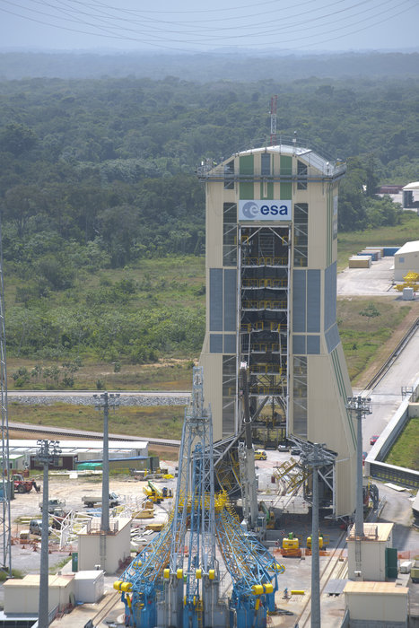
The European Space Agency (ESA) announced that two Soyuz launchers which will fly the first four satellites of Europe’s Galileo navigation system into orbit have arrived at Kourou harbour in French Guiana, completing a journey that took them halfway round the world.
The first two Galileo In Orbit Validation satellites are set to be launched from Europe’s Spaceport on 20 October, with two more following them into orbit by mid-2012. The October launch will be the first flight of a Soyuz rocket from French Guiana.
The two Soyuz ST-B launchers and their Fregat-MT upper stages were carried across the Atlantic aboard Arianespace vessel MN Colibri, arriving on June 18. The rocket hardware left by train from the Soyuz manufacturing plant in Samara, Russia and the Fregat factory in Moscow to St. Petersburg harbour, where it was loaded for shipment, leaving on June 3 for French Guiana.
Soyuz ST-B launchers at Kourou harbor.
According to the ESA, the next step will be the Launcher Flight Readiness Review, due to take place on 21 July. Authorisation will then be given to begin assembling the rocket hardware and deployingthe initial Soyuz ST-B launcher for the first Galileo campaign.
The first two Galileo satellites — known as PFM and FM2, for Protoflight Model and Flight Model 2 – are currently undergoing their final qualification and acceptance tests at Thales Alenia Space in Rome, Italy. Once Satellite Flight Readiness Review has given the green light, both satellites and their ground equipment and launch teams will arrive at the beginning of September for the launch campaign.
Soyuz ST-B is the most powerful version of the famous Soyuz launcher, while the Fregat-MT is an upgraded version of the Fregat upper stage.
Other Soyuz hardware is already in storage at Kourou but only the combination of Soyuz ST-B and Fregat-MT was up to the demanding task of conveying the Galileo satellites into their circular 23,222 km orbits. A European dispenser will hold the satellites in place as they share their ride to orbit, and then release them into their final orbits.
Baseline versions of the reignitable Fregat were previously employed to deliver ESA’s GIOVE-A and -B experimental satellites in 2006 and 2008, which secured the rights to Galileo’s radio frequencies. Fregat-MT carries an additional 900 kg of propellants for its double-satellite load.
The ESA says that October’s launch will be a historic occasion, the first time that a Soyuz launcher lifts off from a spaceport other than Baikonur in Kazakhstan or Plesetsk in Russia.
Because French Guiana is so close to the equator each launch will benefit from Earth’s spin, increasing the maximum payload to geostationary transfer orbit from 1.7 tonnes to three tonnes, says the ESA. As a medium-class launcher, Soyuz will complement Ariane and Vega to enhance the flexibility and competitiveness of Europe’s launcher family. Each three-stage rocket will be assembled horizontally in the traditional Russian manner, transferred to the launch site and moved to the vertical so that its payload can be mated onto it from above. A new mobile launch gantry enables this process, while protecting the satellites and the launcher from the humid tropical environment.
These first four Galileo satellites will form the operational nucleus of the full Galileo satnav constellation, according to the announcement. They are fully representative of the others that will follow them into orbit, combining the best atomic clock ever flown for navigation — accurate to one second in three million years.
Performance of Multiplexed Binary Offset Carrier Modulations for Modernized GNSS Systems
By E. Simona Lohan, Mohammad Z. H. Bhuiyan, and Heikki Hurskainen
A candidate for modernized GNSS civil signals in the L1/E1 band was BOC(1,1), a binary-offset-carrier signal with a “split spectrum” that has negligible impact on the existing GPS signals. However, a signal with better acquisition capabilities and improved multipath performance (while still compatible with the existing GPS signals) is a multiplexed BOC modulation, MBOC(6,1,1/11). The MBOC spectrum can be achieved by following one of several different signal-construction paths with some resulting differences in how a receiver tracks the signal and its associated performance.
INNOVATION INSIGHTS by Richard Langley
IN GEOFFREY CHAUCER’S 1391 ESSAY, A Treatise on the Astrolabe (one of the earliest known instruction manuals in English), he says (with modern spelling) “Right as diverse paths lead the folk the right way to Rome.” He was talking about the use of English rather than Latin or another language to convey the same information. And we now commonly use the shortened version of this expression — all roads lead to Rome — to express the sentiment that a particular problem can be solved in different ways.
So it was with the decision by the United States and Europe to use a common, interoperable signal for the new GPS III civil service and the Galileo Open Service on the L1/E1 frequency of 1575.42 MHz. The road to “Rome” was tedious, long, and a little bumpy at times. A number of studies and a lot of rhetoric centered on how to make the new signal compatible with the legacy GPS L1 signals, the C/A-code and the P(Y)-code, as well as the modernized GPS military signal on L1, the M-code.
A similar compatibility issue had been solved when the M-code was added to the legacy GPS signals, starting with the Block IIR-M satellites. The M-code is a binary-offset-carrier (BOC) signal — a split spectrum signal — that places most of its power near the edges of the allocated GPS frequency bands, thereby having negligible impact on the legacy signals. The M-code modulation, designated BOC(10.23,5.115) and commonly abbreviated BOC(10,5), uses a subcarrier frequency of 10.23 MHz and a spreading code rate of 5.115 megachips per second to achieve the desired spectral separation. This design provides military users with an improved signal with little impact on civil users.
Similar approaches were initially proposed for the new GPS L1C and Galileo E1/L1 OS signals with a BOC(1,1) modulation initially agreed on. However, further studies showed that a signal with better acquisition capabilities and improved multipath performance (while still compatible with the existing GPS signals) was a multiplexed BOC modulation, MBOC(6,1,1/11), formed by multiplexing a wideband signal, BOC(6,1), with a narrow-band signal, BOC(1,1), in such a way that 1/11th of the power is allocated, on average, to the high frequency component. Such a signal has the added benefit that one can choose whether to make use of just the low-frequency component in, say, a simple “mass market” receiver or also use the high-frequency component for more demanding applications.
It turns out that the agreed-upon MBOC spectrum can be achieved by following one of several different signal-construction paths with some resulting differences in how a receiver tracks the signal and its associated performance. In this month’s column, we take a look at some of the options.
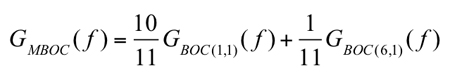
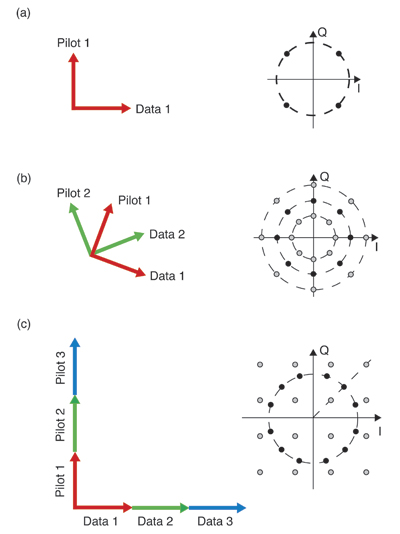
In July 2007, the United States and Europe announced agreement on the use of the multiplexed binary offset carrier (MBOC) modulation as a common baseline for Galileo Open Service signals in the E1 band and GPS L1C signals in the L1 band. According to the most recent Galileo Signal-In-Space Interface Control Document (SIS-ICD; see Further Reading), the MBOC power spectral density (PSD) has been fixed to
(1)
where GBOC(m,n)(f) is the normalized PSD of a BOC(m,n)-modulated pseudorandom noise (PRN) code with sine phasing. The indices m and n are related to the sub-carrier frequency, fsc, and the chip frequency, fc, via m = fsc/frefand n = fc/fref, respectively; fref = 1.023 MHz is the reference C/A-code frequency, and NB = 2fsc/fc = 2m/n is the BOC modulation index.
The MBOC PSD is obtained by taking the data and pilot channels together. The data and pilot channels can use, independently, one of the following modulations: composite binary offset carrier (CBOC) or time-multiplexed binary offset carrier (TMBOC) modulations. CBOC and TMBOC, in turn, have several variants. Since the data and pilot channels are typically processed independently, it is important to understand the differences between various CBOC and TMBOC modulations and this is the primary goal of this article. There are several possible ways to achieve a PSD as given in Equation (1) and they are based on combining the data and pilot channels in the Galileo and modernized GPS systems. The main modulation types for pilot or data channels that can be used in order to achieve (when combined) the MBOC PSD can be summarized as follows:
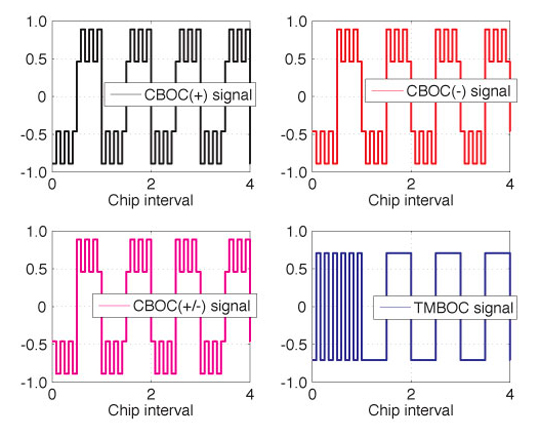
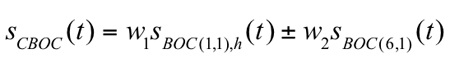
1. The CBOC method: CBOC is formed via a weighted sum or difference of BOC(1,1)- and BOC(6,1)-modulated code symbols (where the BOC(1,1) part is passed through a delay block in order to match the rate of the BOC(6,1) part) as defined in Equation (2):
(2)
where sBOC(1,1),h is the up-sampled BOC(1,1)-modulated code (that is, the code provided at the same rate as the sBOC(6,1) signal), sBOC(6,1) is the BOC(6,1)-modulated code, and w1 and w2 are amplitude weighting factors, chosen in such a way to match (as closely as possible, when both data and pilot channels are considered) the PSD of Equation (1), with w12 + w22 = 1. When the two right-hand terms are added in Equation (2), CBOC(+) is formed; when subtracted, CBOC(–) is formed. A third alternative for CBOC implementation is to use the CBOC(+/–) approach, where the odd-numbered chips are CBOC(+)-modulated and the even chips are CBOC(–)-modulated. The current Galileo SIS-ICD uses a CBOC(+) variant (also called CBOC in-phase) for the E1-B data channel and a CBOC(–) variant (also called CBOC anti-phase) for the E1-C data-less (or pilot) channel.
2. The time-multiplexed BOC (TMBOC) method: the whole signal is divided into blocks of N code symbols with M (<N) code symbols sine-BOC(1,1)-modulated, while N-M code symbols are sine-BOC(6,1)-modulated. The typical shorthand notation for this variety of TMBOC would be TMBOC(6,1,(N-M)/N), referring to the sine-BOC(6,1) component of the signal. This time-domain division may be applied for both pilot and data channels, individually. The choice of the N and M parameter values depends on the desired power percentage of the pilot channel with respect to the data channel. We have shown in earlier work (see Further Reading) that, from the point of view of the MBOC autocorrelation function, TMBOC and CBOC(+) implementations are equivalent, as long as the weights are related to the N and M values using w1 = √(M/N) and w2 = √((N-M)/N). Various TMBOC implementations exist according to the values chosen for N and M and according to whether the BOC(1,1) code symbols are in phase or out of phase with the BOC(6,1) code symbols. For example, for a 50-percent/50-percent power split between the pilot and data channels using in-phase code symbols, M = 9 and N = 11 (that is, TMBOC(6,1,2/11) is used), while for a 75-percent/25-percent power split between the pilot and data channels (again, using in-phase code symbols), M = 29 and N = 33 (that is, TMBOC(6,1,4/33) is used).
A major difference between CBOC and TMBOC signals is that CBOC signals have four different levels (as a weighted sum or difference of two sub-carriers), while TMBOC signals have only two levels. The impact of these differences in the tracking stage of a receiver has been analyzed, for example, by a team of researchers led by Olivier Julien (see Further Reading). They showed that an optimal CBOC receiver should generate a local replica that also has four levels, resulting in a replica encoded on more than just one bit. This complicates the CBOC receiver architecture, compared to TMBOC 1-bit receiver architectures. In terms of performance, a CBOC(–) receiver proved to have the same delay-tracking variance performance as a TMBOC(6,1,4/33) receiver and both slightly outperform a TMBOC(6,1,1/11) receiver. And considering multipath error performance, a TMBOC(6,1,4/33) receiver was shown to give the best performance, followed very closely by a CBOC(–) receiver. Our research extends this earlier study.
Examples of CBOC and TMBOC waveforms are shown in Figure 1. Here, w1 = (10/11) and the TMBOC waveform has every first chip BOC(6,1)-modulated (inside blocks of 11 chips). In the figure, only the first five modulated chips are shown for clarity.
Figure 1. Example of MBOC waveforms for a PRN sequence [1, -1, 1, -1, -1].Our article addresses the following issues: First, we analyze the spectral differences between various CBOC and TMBOC modulations in terms of their effect on receiver performance. Secondly, we look at the navigation data error probability, the tracking error variance in the presence of noise, and the robustness of the signal in the presence of multipath and bandwidth limitations of MBOC variants, by taking into account the spectral differences between the different variants. Thirdly, we justify the choice of CBOC(+) for data channels and CBOC(–) for pilot channels in the Galileo SIS-ICD in terms of these receiver performance criteria.
Spectral Differences of CBOC/TMBOC Modulations
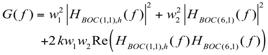
The spectral differences refer to the differences in the PSD of various waveforms. We recall that the PSD is the Fourier transform of the CBOC/TMBOC autocorrelation function. CBOC/TMBOC signals are formed from the convolution of PRN code waveforms, CBOC/TMBOC modulation waveforms, and navigation data (when present). If the same PRN code is used for the BOC(1,1) and BOC(6,1) modulations, some cross-correlation terms appear in the autocorrelation function, which will also appear in the frequency spectrum. Indeed, following the model, after straightforward derivations, we obtain the generic CBOC/TMBOC PSD as:
(3)
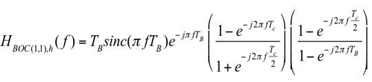
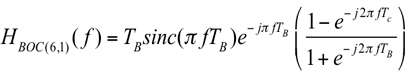
where HBOC(1,1),h(f) and HBOC(6,1)(f) are the following Fourier transforms of the modulation waveforms:
(4)
(5)
Above, TB = TC/12 is the BOC(6,1) sub-interval and sinc(x) = sin(x)/x. The formula given in Equation (3) covers all CBOC/TMBOC cases: k = +1 for CBOC(+) and TMBOC, k = –1 for CBOC(–), and k = 0 for CBOC(+/–), respectively. Equation (3) characterizes either the pilot channel’s PSD or the data channel’s PSD. In order to achieve the PSD of Equation (1), data and pilot channels should be combined. For example, if k = 0, any combination of data and pilot channels is possible in order to attain the PSD. If k ≠ 0, then the data channel should use in-phase combining (k = +1) and the pilot channel should use anti-phase combining (k = –1) or vice versa.
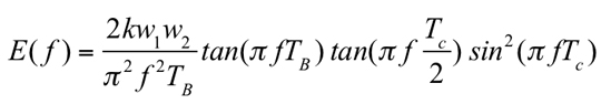
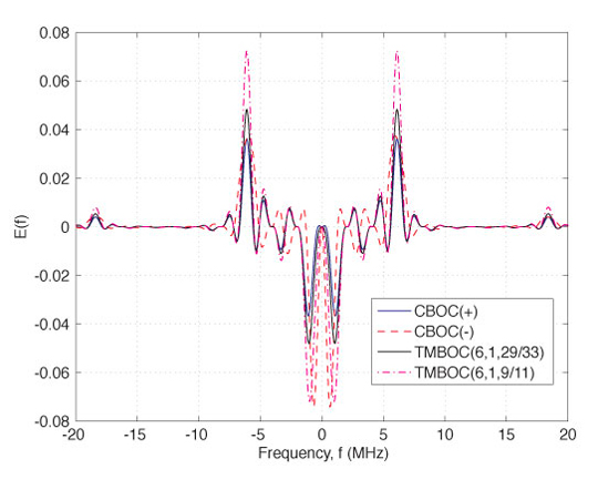
Now, if we take as a reference the PSD of CBOC(+/–) (which, incidentally, is also the PSD of Equation (1)), the spectral differences between the other CBOC/TMBOC modulations and CBOC(+/–) are quantized by the following equation:
(6)
Examples of spectral difference between CBOC(+/–) and each of the following modulations: CBOC(–), CBOC(+), and TMBOC(6,1,(N-M)/N) and each of the following modulations: CBOC(–), CBOC(+), and TMBOC(6,1,(N-M)/N), respectively, are shown in Figure 2. Clearly, these differences are very small.
Figure 2. Examples of PSD spectral differences (linear scale) between various CBOC/TMBOC implementations and CBOC(+/-) assuming an MBOC receiver.
Impact on System Performance
As mentioned before, pilot and data channels typically use different CBOC/TMBOC modulations, in order to achieve an overall PSD as described by Equation (1). Now, based on the derivations we have presented so far, the following questions can be addressed: Which are the most suitable modulations (among the four discussed here; namely, CBOC(+), CBOC(–), CBOC(+/–), and TMBOC) to be used for a pilot channel and for a data channel, respectively; and how will the differences in the PSDs affect the error probability of the decoded signal and the tracking performance of each channel?
Uncoded Error Probability and Fractional Out-of-Band Energy. Data and pilot channels are usually processed independently and then combined (for example, non-coherently) in order to perform the line-of-sight (LOS) signal delay estimation and the navigation data detection. Since different CBOC or TMBOC modulations can be used for the data and pilot channels, one question to be addressed here is what is the most suitable modulation type. Additionally, the carrier-to-noise-density ratio (C/N0) deterioration when another modulation type is employed is also important. These two issues are addressed in this section.
One important spectral parameter that allows us to answer the question about error probability in the decoded data is the so-called fractional out-of-band energy (FOBE), which tells us about the fraction of the signal power remaining outside a certain double-sided bandwidth, Bw. FOBE is related to the power containment factor, used by some authors, via (1 – FOBE(Bw)). Clearly, FOBE depends on the signal modulation type. The higher FOBE is, the greater the deterioration of the signal energy we have after the receiver bandwidth limiting filters, and thus the higher error probability of the decoded signal we have. From the data-channel point of view, correctly decoding the navigation data is very important and therefore, low FOBE is the most important characteris
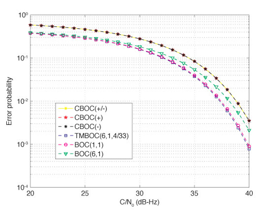
tic when choosing the modulation type. The bit error probability in decoding a binary signal, such as a BOC or MBOC signal, can be computed by taking into account the signal energy deterioration due to filtering. Using the basic formula for computing the bit error probability in decoding a 2-level signal (in the cases of BOC or TMBOC modulation) or a 4-level signal (in the case of CBOC modulation), we can compare the performance of various TMBOC and CBOC modulations in terms of error probability of the decoded data bits, as shown in Figure 3. Clearly, the error probability criterion is more important for a data channel than for a pilot channel. Sine-BOC(1,1) and BOC(6,1) modulations are included in the comparison of Figure 3 as benchmarks. A double-sided bandwidth of 24.552 MHz was considered here, following the choice in the Galileo SIS-ICD.
Figure 3. Detection error probability for CBOC/TMBOC-modulated signals with a 24.552 MHz double-sided bandwidth.
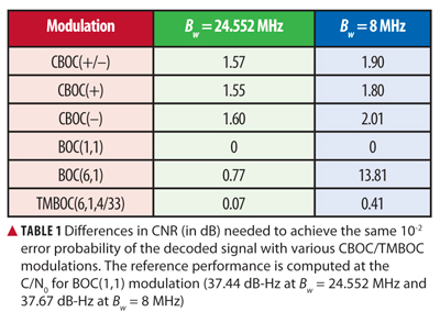
As seen in Figure 3, in terms of the error probability of the decoded signal, BOC(1,1) modulation gives the best results, followed closely by TMBOC(6,1,4/33). In order to achieve an error probability of 10-2, the CNR differences shown in Table 1 are needed for the different modulation types. From Table 1, it can be seen that, among CBOC modulations, the CBOC(+) modulation is the best option from the point of view of decoding the data, and, therefore, it makes it a suitable option for data channels, as chosen in the Galileo SIS-ICD. We remark that the huge CNR gap for BOC(6,1) at Bw = 8 MHz is due to the fact that the power containment of a BOC(6,1) signal is very poor at such a low bandwidth.
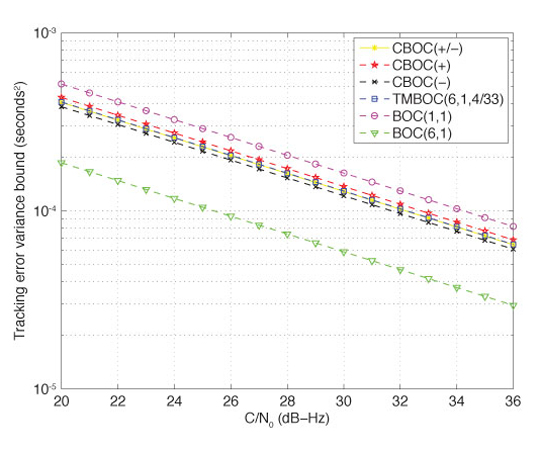
Gabor Bandwidth and Tracking Error Variance. Another important spectral parameter of interest in this analysis is the root-mean-square (RMS) or Gabor bandwidth. A larger RMS or Gabor bandwidth permits a higher accuracy against thermal noise and the tracking accuracy is approximately inversely proportional to the RMS bandwidth. The code-tracking error variance is an important parameter when trying to achieve accurate location estimates. Indeed, a Cramér-Rao lower bound (CRLB) on the tracking error variance has been derived by other researchers. Following the derivation for CRLB on the tracking error variance, we can also compare the performance of various CBOC and TMBOC modulations, as presented in Figure 4. Clearly, this criterion is more important for a pilot channel than for a data channel. A double-sided receiver bandwidth of 24.552 MHz was considered here.
Figure 4. Cramér-Rao lower bound on tracking error variance (in seconds2) for CBOC/TMBOC-modulated signals with a 24.552 MHz double-sided bandwidth.
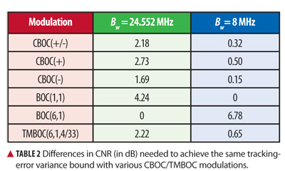
In terms of the tracking error variance bound, which linearly decreases with the CNR (on a dB scale), the CNR differences between various modulations are shown in TablE 2 for a 4-Hz tracking-loop bandwidth. Clearly, from Table 2, CBOC modulations are better in terms of tracking error variance than TMBOC modulation, and, among the CBOC variants, CBOC(–) has the best performance. This justifies the fact that the Galileo SIS-ICD has chosen the CBOC(–) as the best option for pilot channels. We can also see in Table 2 that the bandwidth limitation has an important effect on the tracking error bounds, as expected. At low receiver bandwidth (such as 8 MHz), the differences between various modulations are rather small, while at high or infinite bandwidths, BOC(6,1) modulation is by far the best option, followed by CBOC(–) with a 1.69 dB gap in CNR (that is, CBOC(–) requires an additional 1.69 dB in order to achieve the same tracking error performance as BOC(6,1)).
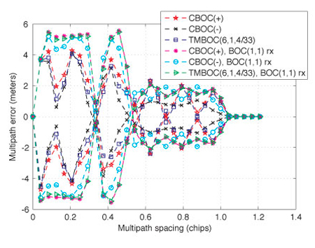
Multipath Error Envelope. The typical procedure for evaluating the performance of a multipath-mitigation technique is via the multipath error envelope (MEE). The MEE curves are obtained for two extreme phase variations of a multipath signal with respect to the LOS component while varying the multipath (that is, second path) delays from 0 to 1.2 chips at maximum, since the multipath errors become less significant after that. The upper multipath error envelope can be obtained when the paths are in-phase (that is, 0° phase difference) and the lower multipath error envelope when the paths are out-of-phase (that is, 180° phase difference). In MEE analysis, several simplifying assumptions are usually made in order to distinguish the performance degradation caused by the multipath only. Such assumptions include zero additive white Gaussian noise, ideal infinite-length PRN codes, zero residual Doppler shift, and zero initial code-delay error.
The MEE curves are generated here for different variants of MBOC implementation. The multipath performance of these MBOC variants with a BOC(1,1)-modulated reference receiver is also presented. In the MEE generation, the second path amplitude was fixed at 3 dB lower than the LOS component. The MEE curves were generated for a 24.552 MHz double-sided bandwidth. The narrow early-minus-late (nEML) correlator with an early-late correlator spacing of 0.0833 chips was used here as a tool for evaluating the performance of the different MBOC variants in the presence of multipath. The nEML is based on the idea of narrowing the spacing between the early and late correlator pair, where the choice of correlator spacing depends on the receiver’s available front-end bandwidth along with the associated sampling frequency.
MEE curves are shown for all of the examined MBOC variants in Figure 5. It can be observed from the figure that CBOC(–) has the best multipath mitigation performance followed by the TMBOC(6,1,4/33) and CBOC(+) variants. A similar conclusion can be drawn when a BOC(1,1) reference receiver is used instead of the respective MBOC reference receiver. However, from Figure 5, it is obvious that there is a moderate performance degradation when a BOC(1,1) reference receiver is used instead of the respective MBOC version, as expected intuitively.
Figure 5. Multipath error envelope curves for a narrow early-minus-late correlator with a 24.552 MHz double-sided bandwidth.
Simulation Results in Multipath Fading Channel
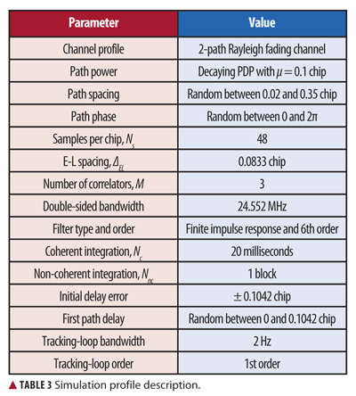
Simulations have been carried out in closely spaced multipath scenarios for different MBOC variants with a finite front-end bandwidth. The simulation profile is summarized in Table 3. A Rayleigh fading channel model is used in the simulation, where the number of channel paths is fixed to two. The successive path separation is random between 0.02 and 0.35 chips. The channel paths are assumed to obey a decaying power delay profile (PDP).
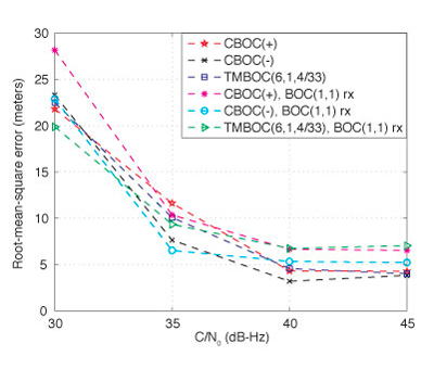
The received signal duration is 0.8 seconds for each particular C/N0 level. The tracking errors are computed after each NcNnc-milliseconds interval (in this case, NcNnc = 20 milliseconds). In the final statistics, the first 600 milliseconds are ignored in order to remove the initial error bias that may come from the delay difference between the received signal and the locally generated reference code. Therefore, for the above configuration, the left-over tracking errors after 600 milliseconds are mostly due to the effect of multipath only. We ran the simulations for 1,000 statistical points, for each C/N0 b> level. The RMS error (RMSE) of the delay estimates can be plotted in meters, by using the relationship RMSEm = RMSEchips•c•Tc, where c is the speed of light, Tc is the chip duration, and RMSEchips is the RMSE in chips. An RMSE versus C/N0 plot for the given multipath channel profile is shown in Figure 6.
As seen in the figure, the CBOC(–) reference receiver has the best multipath mitigation performance under a good
C/N0 (that is, 40 dB-Hz and higher) followed by the other two MBOC variants (CBOC(+) and TMBOC(6,1,4/33)), which exhibit almost similar performance. A similar conclusion can be drawn for the BOC(1,1) reference receiver, where the CBOC(–)-modulated transmitted signal with BOC(1,1) reference receiver showed the best multipath mitigation performance among all three of the studied MBOC variants. In Figure 6, we observe that the small performance deterioration caused by use of a BOC(1,1) reference receiver is visible only under good C/N0 conditions (that is, 40 dB-Hz and higher).
Figure 6. Root-mean-square error versus carrier-to-noise-density ratio for different MBOC variants in a two-path fading channel with 24.552 MHz double-sided bandwidth.
Conclusions
This article discusses the spectral differences between CBOC and TMBOC modulations and their impact on system performance. The exact frequency-domain form of the PSD for CBOC and TMBOC waveforms has been shown and the impact on tracking error variance bounds and on the error probability of the demodulated signal has been discussed. In addition, the multipath mitigation performances of different MBOC variants were presented in terms of RMSE and multipath error envelopes. It was shown that the CBOC(–) variant is the best variant in terms of multipath mitigation and tracking error variance, while TMBOC behaves better than CBOC in terms of error probability of the demodulated data. We also showed that the spectral differences and the differences between CBOC and TMBOC variants in terms of the two considered performance criteria are rather small, especially when the receiver bandwidth is not very high, and, therefore, several variants of MBOC can indeed be used for design and research purposes.
Acknowledgments
The research leading to the results presented in this article received funding from the European Union’s Seventh Framework Programme (FP7/2007-2013) under grant agreement number 227890 (the Galileo-Ready Advanced Mass Market Receiver–GRAMMAR–project). This research work has also been supported by the Academy of Finland and by the Tampere Doctoral Programme in Information Science and Engineering. Particular thanks are also addressed to Stephan Sand from the German Aerospace Center (DLR), Institute of Communications and Navigation, for his useful comments.
Elena Simona Lohan has been an adjunct professor in the Department of Communications Engineering at Tampere University of Technology (TUT) in Hervanta, Finland, since 2007. She obtained her Ph.D. degree in wireless communications from TUT. She also graduated with an M.Sc. in electrical engineering from “Politehnica” University of Bucharest, and with a diplôme d’études approfondies in econometrics from Ecole Polytechnique, Paris. Lohan is currently leading the research activities in signal processing for wireless communications in the Department of Communications Engineering at TUT.
Mohammad Zahidul H. Bhuiyan is a researcher in the Department of Communications Engineering at TUT. His main research areas are multipath mitigation and software receiver design for satellite-based positioning applications.
Heikki Hurskainen received an M.Sc. degree in electrical engineering and a doctoral degree in computing and electrical engineering from TUT in 2005 and 2009, respectively. Currently, Hurskainen is a senior research scientist in TUT’s Department of Computer Systems where he works on satellite navigation research projects.
Navstar GPS Space Segment/User Segment L1C Interfaces, Rev. A, Interface Specification, IS-GPS-800A, prepared by Science Applications International Corporation, El Segundo, California for the Global Positioning System Wing, Systems Engineering and Integration, Los Angeles Air Force Base, California, June 2010.
• Binary Offset Carrier Modulation
“Low Complexity Unambiguous Acquisition Methods for BOC-modulated CDMA Signals” by E.S. Lohan, A. Burian, and M. Renfors in International Journal of Satellite Communications and Networking, Vol. 26, No. 6, 2008, pp. 503–522, doi: 10.1002/sat.922.
“Binary-Offset-Carrier Modulation Techniques with Applications in Satellite Navigation Systems” by E.S. Lohan, A. Lakhzouri, and M. Renfors in Wireless Communications and Mobile Computing, Vol. 7, No. 6, 2007, pp. 767–779, doi: 10.1002/wcm.407.
“Overview of the GPS M Code Signal” by B.C. Barker, J.W. Betz, J.E. Clark, J.T. Correia, J.T. Gillis, S. Lazar, K.A. Rehborn, and J.R. Straton, III, in Proceedings of 2000: Navigating into the New Millennium, the 2000 National Technical Meeting of The Institute of Navigation, Anaheim, California, January 26–28, 2000, pp. 542–549.
“The Offset Carrier Modulation for GPS Modernization” by J.W. Betz, in Proceedings of Vision 2010: Present and Future, the 1999 National Technical Meeting of The Institute of Navigation and 19th Biennial Guidance Test Symposium, San Diego, California, January 25–27, 1999, pp. 639-648.
• Multiplexed Binary Offset Carrier Modulation Implementations and Comparisons
“Future Wave: L1C Signal Performance and Receiver Design” by T.A. Stansell, K.W. Hudnut, and R.G. Keegan in GPS World, Vol. 22, No. 4, April 2011, pp. 30–36,41.
“Analytical Performance of CBOC-modulated Galileo E1 Signal Using Sine BOC(1,1) Receiver for Mass-market Applications” by E.S. Lohan, in Proceedings of PLANS 2010, IEEE/ION Position Location and Navigation Symposium, Indian Wells, California, May 4–6, 2010, pp. 245–253, doi: 10.1109/PLANS.2010.5507207.
“MBOC and BOC(1,1) Performance Comparison” by N. Hoult, L.E. Aguado, and P. Xia in The Journal of Navigation, Vol. 61, No. 4, October 2008, pp. 613–627, doi: 10.1017/S0373463308004918.
“The MBOC Modulation: A Final Touch for the Galileo Frequency and Signal Plan” by J.A. Avila-Rodriguez, G.W. Hein, S. Wallner, J.L. Issler, L. Ries, L. Lestarquit, A. De Latour, J. Godet, F. Bastide, T. Pratt, and J. Owen in Inside GNSS, Vol. 2, No. 6, Se
ptember-October 2007, pp. 43–58.
“Two for One: Tracking Galileo CBOC Signal with TMBOC” by O. Julien, C. Macabiau, J.L. Issler, and L. Ries in Inside GNSS, Vol. 2, No. 3, Spring 2007, pp. 50–57.
“MBOC: The New Optimized Spreading Modulation Recommended for Galileo L1 OS and GPS L1C” by G.W. Hein, J.A. Avila-Rodriguez, S. Wallner, J.W. Betz, C.J. Hegarty, J.J. Rushanan, A.L. Kraay, A.R. Pratt, S. Lenahan, J. Owen, J.L. Issler, and T.A. Stansell in Inside GNSS, Vol. 1, No. 4, May-June 2006, pp. 57–65.
• Gabor Bandwidth and Cramér-Rao Bound
Spread Spectrum Systems for GNSS and Wireless Communications by J.K. Holmes, published by Artech House, Inc., Norwood, Massachusetts, 2007.
“A Family of Split Spectrum GPS Civil Signals” by J.J. Spilker, Jr., E.H. Martin, and B.W. Parkinson, in Proceedings of ION GPS-98, the 11th International Technical Meeting of the Satellite Division of The Institute of Navigation, Nashville, Tennessee, September 15–18, 1998, pp. 1905–1914.
• Narrow Early-Minus-Late Correlation
“Extended Theory of Early-Late Code Tracking for a Bandlimited GPS Receiver” by J.W. Betz and K.R. Kolodziejski in Navigation: Journal of the Institute of Navigation, Vol. 47, No. 3, 2000, pp. 211–226.
The recent broadcast of the first CDMA signal from the new GLONASS-K satellite culminates a long series of events that began in 1989. A key participant gives a first-hand account of the history of many meetings, formal and informal, that created true interoperability between the two major satellite systems, giving users a modern GNSS in action.
October 18, 1989, the Queen Elizabeth Auditorium in London, around 8:30 am. Unknown to me, two 60-minute periods were about to imprint themselves indelibly on my memory.
I walked up the stairs to the exhibition booth of my company, Ashtech, at The Royal Institute of Navigation conference. My good friend, the late Ann Beatty, met me and asked, “Any news from home?”
I thought it was just a casual customary question, and replied: “Thanks, all OK.” She had a strange look on her face. She continued: “Are all your family really OK?” I replied again: “Thanks, all good.” She then realized that I had no clue about the cataclysmic event that had hit the San Francisco Bay area. She abruptly said, “Don’t you know? The big one came! The big earthquake hit San Francisco!”
Californians know the rumors that when The Big One comes, Nevada will have ocean frontage. Now she was telling me that The Big One came! I rushed to the phone, and the recorded AT&T message said, “All lines to your area are out of service.” It took me another hour to find out that this was not yet The Big One, and that my family was safe. I will never forget these 60 minutes of my life. Never!
Nor will I ever forget the events of the next 60 minutes.
After the stress had settled a bit, a delegation from the Russian Space Agency visited our booth. First they expressed their sympathy regarding the earthquake. Then we discussed GPS technology and its similarities with GLONASS. Both systems were fairly new then, although GPS had started first, with a Block I launch in 1978, followed by GLONASS with a launch in 1982. At the time we met in London, GPS was flying 12 satellites, and GLONASS also had 12 in orbit.
The Russian delegation visited all GPS manufacturers’ booths in the exhibition hall and then gathered in the coffee area for their private discussions. A few hours before the conference closed, they returned to our booth and said, “We want to combine GPS and GLONASS, and you are our first choice.” Simply put, I was fascinated and excited.
After working out visa and travel details, four months later I arrived in Moscow in the cold days of February 1990. It was still the Soviet Union.
I had grown up in Iran where the U.S.S.R. was our neighbor to the north. Remembering the global political landscape of my childhood days, I felt both fascination and fear as my airplane landed at Moscow airport.
Upon meeting the people who greeted me at the airport, my fears disappeared, and my fascination grew stronger.
Our first formal meeting took place in the Institute of Space Device Engineering (ISDE), a division of the Russian Space Agency that was responsible for the GLONASS program. The opening photo shows me with the late Dr. Nikolay Yemelianovich Ivanov, director of the GLONASS program, at that first meeting.
I want to focus a bit on the GLONASS team and applaud them for their efforts. What makes the GLONASS team special is that they worked under much harder political and financial conditions than the GPS or Galileo teams. But still they were able to make the project successful. The Soviet Union and later Russia went through huge political, economic, social, and geographical revolutions, but the GLONASS team managed to keep the satellite navigation program alive and successful.
Galileo’s management, while enjoying much more stability and financial luxury, can certainly appreciate and understand the significance of what the GLONASS team accomplished. Galileo also benefitted from the European integration of 27 countries, while the Soviet Union disintegrated into 15 separate nations.
Despite all their heroic work, individuals on the GLONASS team have received almost no international recognition. At home they went unnoticed, due to their political situations. For example, the highest international recognition that Dr. Ivanov received was that he became a member of the GPS World Advisory Board, which I facilitated. In this article, I want to salute some members that I know and at least keep their names and photos recorded in the GPS World archives.
In the first meeting, everyone recognized and emphasized the great potential of combining GPS and GLONASS for a variety of applications. I became more assured of the deep desires of my hosts to make this happen. They had prepared detailed charts and plans, especially for high-precision applications. They also gave me the GLONASS Interface Control Document (ICD) for the first time.
We signed a cooperation protocol and agreed to explore technical details in our next meeting, which occurred a few months later. There I began to know Dr. Stanislav “Stas” Ulianovich Sila-Navitsky, at that time the chief scientist of Dr. Ivanov’s team. Later he became my vice president in three companies that I founded. He also became my best friend of 19 years, before he passed away on May 7, 2010.
We had several meetings in Moscow and one in Paris in the headquarters of our partner SAGEM.
I have wonderful memories of all the meetings. One meeting in Paris included General Leonid Ivanovich Gusev, the head of ISDE. One evening Stas called my hotel room and asked me to cancel our dinner at a famous French restaurant and instead join them for a “real dinner.” Apparently General Gusev was tired of French food! The real dinner took place in the General’s hotel room, and the menu consisted of dark Russian bread, Russian kielbasa sausage, Russian seledka herring, and an abundance of Russian vodka.
Our first announcement of combining GPS and GLONASS was published in GPS World magazine, in only its second issue, March/April 1990. That year we had a poster banner in our Institute of Navigation exhibition, showing the American flag and the Soviet flag (hammer and sickle) next to each other. My very good friend, Colonel Gaylord Green, the second director of the GPS Joint Program Office, refused to have his picture taken with me in front of that banner. Instead, we stood over to another side of the booth for his photo.
A few months after the Paris meeting, the political process known as perestroika began and caused the Soviet Union to end. Life became extremely difficult for Russians.
I called Stas to discuss the situation. We concluded that we had no choice but to continue the plan on our own if we wanted to combine GPS and GLONASS. I went back to Moscow several times, and in February 1992 officially opened the Moscow office of Ashtech. This office is still operational in Moscow with about 10 percent of the original team. It is now in the process of being purchased by Trimble Navigation. What a turn of events!
In 1996 we introduced the first combined GPS and GLONASS receiver; the product announcement appeared in GPS World, July 1996
Back home in the United States, the situation was different. Supporting GLONASS was an unpatriotic act. The most prominent figures of GPS teased me for wasting my time with GLONASS. The news favored their arguments: the Russian economy was going downhill. In September 1998, the Russian ruble collapsed more than 300 percent within a week. Banks closed. Even Coca Cola was not able to pay its employees in Russia because of bank closures. Many western companies left Russia. During that period, I intentionally stayed longer times in Moscow and managed to pay our employees without a day of delay. Furthermore, a more than three-fold rate change in favor of the dollar made our employees relatively rich, because their salaries were based on the U.S. dollar.
I remained confident that GLONASS would succeed because I had seen the enthusiasm and dedication of GLONASS management and engineers.
My Ashtech partners wanted to take the company public to recoup their investments. They thought Wall Street would negatively view GLONASS and the Russian connection. So my aspiration did not match theirs, and I started Javad Positioning System (JPS) in 1996. About 90 percent of the staff engineers followed me to JPS.
One of John Scully’s vice presidents did to Ashtech what Scully did to Apple. Meanwhile JPS became very successful, as Apple did when Steve Jobs returned.
Subsequent to another event and termination of some obligations and commitments, I started JAVAD GNSS in June 2007. Almost all of the key people followed me again. Our current team has a history of working together for close to 20 years.
In JAVAD GNSS we raised the bar of GPS/GLONASS integration to a higher level and focused in two new directions. The first was to eliminate the problem of GLONASS inter-channel biases, which is inherent to the GLONASS frequency-division multiple access (FDMA) signal structure. The second was to support the opinion of GLONASS engineers who were pushing for a new code-division multiple access (CDMA) signal for GLONASS, similar to the GPS signal.
We resolved the GLONASS inter-channel biases issue around 2009 and announced, “Our GLONASS is as good as GPS.”
On the second front, we worked with the top managements of ISDE and the Information Analysis Center (IAC) of the Russian Space Center to demonstrate the advantages of CDMA for high-precision applications.
Some years ago, Stas had confided in me that the issue of CDMA was nothing new, and had been extensively deliberated at all levels of various GLONASS organizations during the early design phase of the system. The result of all these discussions was that engineers and technical people favored CDMA, but the higher management, mostly influenced by the military organizations, held out for FDMA. The reason for favoring FDMA is still a secret, though some believe that they just wanted to be different from GPS and did not see much advantage in CDMA. Some also believed FDMA gave better jamming protection.
Of course in those very early days, no one imagined using GPS or GLONASS for high-precision applications, and as such truly there was not much difference between CDMA and FDMA. Much later, the notion of using carrier phase of GPS and GLONASS signals for high-precision applications was discovered, and then the advantages of CDMA became relevant, as Dr. Ivanov also hinted in our first meeting.
After we combined GPS and GLONASS, and as a lot of our worldwide users began comparing the two systems, the issue of CDMA versus FDMA again came up for discussion among the GLONASS authorities.
More recently, since 2007, we had several meetings in the offices of ISDE in Moscow, in IAC in Korolev (the Russian Space City), and several in our JAVAD GNSS office in Moscow. Most importantly, we had several meetings in my Moscow apartment, enhanced by Russian vodka and the best Armenian cognac, courtesy of Sergey Revnivykh, head of IAC. All meetings were open and candid, discussing and demonstrating the advantages of CDMA, in support of the ISDE engineers who were reluctant to express their opinion above certain levels.
I also met with the head of the Russian Space Agency, Dr. Anatoly Nikolayevich Perminov, who personally supported and sponsored me in obtaining an extended Russian residency visa. Let me also express my appreciation for receiving the Medal of Honor from the Russian Cosmonauts Federation, along with the official astronaut watch. I don’t understand the reason for receiving a Kalashnikov AK-47 semi-automatic rifle from ISDE for my birthday. I wonder how I can transport it home!
General Anatoly Shilov (deputy director of the Russian Space Center), Dr. Vicheslav Dvorkin (GLONASS deputy general designer), Sergey Revnivykh, Viktor Kosenko (first deputy of chief GLONASS designer) and Sergey Karutin (GLONASS senior scientist) are the new generation of GLONASS leaders who deserve credit for supporting CDMA on GLONASS. Recently, a new GLONASS-K sat-ellite was launched, transmitting an experimental CDMA signal in addition to the legacy signals. Almost immediately, we announced tracking of the new GLONASS-K satellite and its new L3 signal details, hours after it started transmitting. See GPS World archives and our website for details of this signal which seems, in all aspects, as good as GPS.
Another new issue of significant international concern was a new frequency for GLONASS. This issue was more political than technical, and is discussed under the umbrella of interoperability.
In the early days of my frequent travels to Russia, the KGB probably suspected that I was a CIA agent — and the CIA probably suspected that I was a KGB agent! I would not be surprised if both the CIA and KGB monitored every bit of my travels and activities. After some years, the San Francisco airport authorities stopped interrogating me for my activities in Russia any time I came back home. Perhaps because of their deep investigations, I earned the trust and friendship of both sides, and their confidence that I had nothing in mind other than helping to integrate GPS and GLONASS. I was an unofficial member and friend of both U.S. and Russian delegations during the so-called interoperability discussions since 2007, which sometimes touched on the CDMA issue as well.
Some of the most fruitful and friendly discussions between the U.S. and Russian delegations occurred in my apartment in Moscow, after their official meetings. Ken Hodgkins of U.S. State Department; Mike Shaw, director of the National Space-Based Positioning, Navigation, and Timing Coordination Office; David Turner, director of the Center for Space Policy & Strategy; Scott Feairheller of the U.S. Air Force; and Tom Stansell, consultant to the GPS Wing were some of my honored guests.
The new GLONASS frequency discussions are still in progress, and I am proud to host and support both sides the best that I can. Sometimes it is fun to observe that discussions resemble poker games where hands are known to all sides, but players still try to bluff each other! Let’s leave it at that for now.
In May of this year, I had a conversation with General Anatoly Shilov, now second-in-command of the Russian Space Agency, reporting to the first deputy of the minister of defense, General Vladimir Popovkin, who recently replaced Dr. Perminov as head of the Russian Space Center. This is an indication of increased attention and support from the Russian government to its GLONASS program. In our conversation, General Shilov was enthusiastic and optimistic that the GLONASS program will move forward faster.
GLONASS has proven to be a real and reliable complement to GPS. If it were not for the failure of the launch of three GLONASS satellites in December 2010, its constellation would be complete and fully, globally operational today. It will happen soon. Sergey Revnivykh estimates that currently the system has 99.8 percent global coverage.
Today, a truly reliable and fast RTK is not possible without combining GPS and GLONASS satellites.
The most recent testimony to the success of GLONASS comes from the long-time GLONASS opponents who once criticized me for supporting the system. Recently they had to pay a lot of money to acquire the first company that I founded in Moscow, which they believed would never survive.
This year at JAVAD GNSS, I and most of my original employees and GLONASS designers are celebrating our 20th year in Russia, and we are working harder to make the integration of GPS and GLONASS even better.
On May 7, 2010, Stas lost to leukemia. He was not present to witness the successful introduction of our TRIUMPH-VS receivers. My refrigerators in Moscow are full of medicines that he brought for me any time I had a little cold. I miss him a lot, and our team is dedicated to following the path that Stas loved so much.
I want to briefly summarize the current status and the future of GPS and GLONASS from the users’ point of view.
GLONASS now has 24 satellites transmitting FDMA signals in two frequency bands. The failure in the last launch to deploy three more satellites delayed completion of the constellation to the end of 2011. The good thing about GLONASS is that both of its L1 and L2 signals are not encrypted and give better data than GPS P1 and P2 that are encrypted.
GLONASS is considering a plan to add CDMA signals to all satellites and not suffer from inter-channel biases. But it will take about 10 years for this plan to become complete for public use, even if the plan is approved and followed. At JAVAD GNSS, we have already mitigated the effect of GLONASS inter-channel biases to the accuracy of better than 0.2 millimeters. We made GLONASS FDMA the same as GPS CDMA by adding some innovations (patent pending) and enhanced algorithms.
The GPS plan is to add a third frequency signal (called L5) and add an unencrypted signal in L2. But it will take several years to have enough new satellites transmitting these new signals to make them usable for daily work.
In the near term, we have two complete systems, consisting of about 30 GPS and 27 GLONASS satellites. The current non-encrypted GLONASS signals give it an edge over the current GPS encrypted signals, given the fact that we have mitigated the GLONASS FDMA inter-channel biases.
GLONASS is also enhancing its control segment to better monitor GLONASS satellites and improve the system’s clock and orbit parameters. Most of these errors are cancelled in differential and high-precision applications anyway.
Existence of two complete and free systems, GPS and GLONASS, will place some doubt on the future of Galileo, as it will be extremely difficult for Galileo to hope to collect money from users to fund itself. The addition of Galileo, as a third system, will not really add much benefit for users anyway. The only push for deploying Galileo must come from some European military organizations to support their specific interest.
I have been extremely fortunate also to have had the opportunity to work on GPS from its early days, co-pioneering high-precision applications at Trimble Navigation. I owe a lot to Charlie Trimble, who helped me to lift myself up when I sought refuge in the United States in 1981. He taught me GPS as well as dedication in business. I also benefitted from Sunday meetings with Dr. Bradford Parkinson, the first program director of GPS, who was and still is a board member of Trimble Navigation. I am curious to find out how Brad, as a board member, voted in the recent matter of the purchase of Ashtech. Since leaving Trimble, my innovative products at Ashtech, JPS, and JAVAD GNSS have been well documented through the years in GPS World.
My emphasis on GLONASS in this memoir is only to record some histories and recognize GLONASS and some of its pioneers who were often overlooked. GPS is already a well-known, well-established system and is the backbone of GNSS.
As a final note, let me add that our current JAVAD GNSS products have the option of tracking all current and future signals of GPS, GLONASS, QZSS, and Galileo. Yes, Galileo too!
Plus: Locata as Alternative PNT, Indian SBAS, Galileo Launch
Slow but steady progress of the Working Group (WG) convened by the Federal Communications Commission (FCC) to study the GPS overload/desensitization issue is related in the group’s Third [monthly] Pogress Report, filed with the FCC on May 16. For the third consecutive time, the report contains little in terms of actual results of testing for interference/desensitization of GPS receivers by the proposed LightSquared terrestrial signal. It continues to carefully lay out the ground rules adopted by several subteams for testing the particular receivers in their domain. As of the date of filing, it reported, “testing is underway for six device categories and has been completed for the Space-Based Receivers category.”
As related in May’s The System, the Working Group has self-divided into sub-teams.
Aviation Sub‐Team. Laboratory testing was scheduled to be completed by May 20, conducted by Zeta Associates. The team’s report is being compiled, and some receivers were to be made available for field testing near Las Vegas.
The Federal Aviation Administration (FAA) issued a flight advisory warning pilots that GPS service in one area of Nevada could be “unreliable or unavailable” May 16–27, during LightSquared testing. Tests were to be conducted in six-hour blocks.
“Pilots are strongly encouraged to report anomalies during testing to the appropriate ARTCC to assist in the determination of the extent of GPS degradation during tests,” said the advisory.
Cellular Sub‐Team. Two of the three laboratories engaged to perform radiated and conducted testing have added work shifts to complete their processes by the TWG’s deadline; the third lab is being configured. Forty-five models of GPS-enabled cell phones will undergo testing, following a detailed procedure described in Appendix D to the report.
General Location/Nav Sub‐Team. This team recently added new members representing public safety users at the request of the National Public Safety Telecommunications Council (NPSTC). See related article, “LightSquared Interference with Emergency Service.“ The sub‐team has accumulated live‐sky GPS test data for use in dynamic testing scenarios, and plans further field tests in the Las Vegas, Nevada, area, described in Appendix G.
High-Precision, Networks, Timing. The sub teams have completed testing of all devices in the NAVAIR lab facility. Some team members expect to have some receivers of the same models that have been tested by NAVAIR available for field testing in Las Vegas, and are working to develop test procedures for the field tests.
Space-Based Receivers. The team completed its laboratory testing activities as reported on April 16, and is now reviewing the initial draft analysis of the impacts.
Senate Letter
Meanwhile, the U.S. Senate is showing increasing signs of life in response to the problem. As of May 23, a total of 32 senators had signed a letter to the FCC initially drafted on April 15 by two U.S. senators from the heartland, Pat Roberts (Republican, Kansas) and Ben Nelson (Democrat, Nebraska). The joint public letter urges action in the form of “asking the FCC to take all necessary steps to protect GPS.”
What sway, if any, the Senate holds over the FCC, which forms part of the executive (presidential) branch of government, remains unclear. However, the letter does signal some heightened interest in Washington, presumably as a result of hearing from constituents. Kansas and Nebraska, of course, have large-scale farming activity, in which precision agriculture driven by GPS plays a significant role.
The two original authors state that “the International Bureau, a sub-organization within the FCC, granted a conditional waiver to allow a single company, called LightSquared, to build tens of thousands of ground stations that may cause widespread interference to neighboring GPS signals.”
The letter goes on to outline the many key roles that GPS plays in economic activity and specifically in “economic recovery,” public safety, aviation, and national defense. “Reliable GPS affects virtually every American,” Nelson and Roberts assert.
They close by “calling on the FCC to ensure that GPS is not compromised in any way. To do so, the full commission must be involved and require LightSquared to objectively demonstrate non-interference as a condition prior to any operation of its proposed service. Anything less is an unacceptable risk to public safety.”
The latest signer, Senator Chuck Grassley of Iowa, writes on his website that “Given the FCC’s haste so far, I worry that LightSquared will not have interference problems resolved before given the green light to become fully operational. Farmers shouldn’t have to worry that they’re planting the correct seed or applying the precise amount of fertilizer needed for the soil to optimally produce the crop, and ambulance drivers shouldn’t have to weather taking a wrong turn or driving into a ditch because a new system is scrambling their existing navigational technology.”
Grassley adds, “If anything, the shadows around the LightSquared project should have led the FCC to proceed with caution rather than step on the gas. Yet the opposite happened. The agency originally planned to take public comment on a key regulation necessary for green-lighting the project for only one week. The commission relented and held the comment period open longer only after consumers and affected businesses protested.”
Defense. Congressman Mike Turner included language in the National Defense Authorization Act (NDAA) that requires the Secretary of Defense to notify Congress if he determines there is widespread interference with the military’s use of GPS caused by a commercial communications service. Turner, the House Armed Services Subcommittee chairman on Strategic Forces, has legislative jurisdiction over space and satellite systems, and included the provision in his Mark of the NDAA.
LightSquared Interference with Emergency Services, Public Safety
Law enforcement, emergency medical service (EMS), and fire first-responders in the state of New Mexico who participated in LightSquared/GPS interference testing at Holloman Air Force Base have submitted reports verifying a negative effect of LightSquared transmissions on their GPS equipment.
A cover letter from the New Mexico E-911 program director states that the reports “substantiate concerns that the LightSquared network will . . . jeopardize 911 and public safety nationwide.”
The director of emergency services for Otero County, New Mexico, writes that “during the testing process the [ambulance’s automatic vehicle location] unit was limited to only being able to see 7 satellites at any location and upon moving just 50 yards from our position at the test site towards the [LightSquared] tower were diminished to 3 or 4 satellites and at 60 yards unable to establish any satellite connections. This is still approximately 1/8 of a mile from the tower.”
The tests were conducted on April 15 and 16 of this year at Holloman Air Force Base, in a live sky environment.
Locata Flight Results; ICAO to Weigh for Alternative PNT
“The Need for an Alternative PNT” was presented to the International Civil Aviation Organization’s (ICAO) 10th meeting in Montreal, Canada, on May 19 by the Australian delegation, proposing a new method for alternative position, navigation, and time (APNT). ICAO accepted the paper, and the Locata technology it describes, placing it on the table as a potential back-up to GPS. The organization will take up the discussion at its next meeting in October.
Locata Corporation of Griffith, Australia, also released preliminary post-processing analysis on data collected during its APNT flight trial on May 9. An aircraft fitted with a Locata receiver and several truth-reference devices recorded data for three hours while flying at approximately 7,000 feet. The Locata receiver tracked a ground-based network of six LocataLites, which provided positioning signals to cover an area of approximately 1,500 square kilometers. The aircraft flew pre-defined patterns that gave varying distances to LocataLites (3–49 kilometers) during the test.
During this trial, the Locata first acquired and tracked LocataLite signals at a range of 51.9 kilometers, according to the company, which provided an early-stage assessment of the performance of the Locata pseudorange-based (code) solution against a high-precision carrier-phase differential GPS solution. Figure 1 shows the difference in East, North, and Height between the high-precision GPS truth carrier solution and the Locata code solution. Relative to the high-precision GPS, the Locata code solution has a 95 percent RMS in horizontal of 2.1 meters and 3.2 meters in vertical. The company attributed the larger difference in the vertical to worse dilution of precision in the vertical component for this specific physical deployment of its network. Over this test data analysis, the Locata’s average VDOP of 3.3 compared to an average HDOP of 1.5.
One test objective, the company stated, was to obtain information on the significant tropospheric effects inherent in a ground-based system over these sorts of ranges. Further detailed analysis is now underway to measure and then reduce the residual biases present in the Locata code solution. For this first-pass data analysis these biases are approximately –0.8 meters in North and –1.1 meters in height. When these residual biases are further analyzed and reduced, Locata anticipates that the 95 percent RMS code-solution accuracies will improve to better than 1 meter horizontal and 2.5 meters vertical.
Locata emphasized that this is an early-stage analysis of first flight tests, expressly designed to provide data for a better understanding of the Locata system’s performance characteristics in ICAO-type APNT applications, and for a USAF-contracted LocataNet deployment at White Sands Missile Range that will cover more than 6,500 square kilometers. Further flight trials are planned in the near future to refine the system.
In Q3/2011 Locata expects papers to be published on carrier-phase performance observed over multiple flights, with presentations during ION 2011 Conference in Portland, Oregon.
Figure 1. Difference in East, North, and Height between preliminary Locata pseudorange-based solution and high-precision differential carrier-phase GPS solution.
Indian SBAS Aloft
The Indian Space Research Organisation successfully launched a GSAT-8 satellite, carrying a GPS-Aided Geo Augmentation Navigation (GAGAN) satellite-based augmentation system (SBAS) transponder, on May 21, aboard an Ariane-V launch vehicle, from Kourou, French Guiana. The satellite will be stationed at 55 degrees east longitude.
Galileo Picks October 20
The first two operational/validation satellites of the Galileo project received a launch date of October 20 of this year. Antonio Tajani, European Commission vice-president for industry and entrepreneurship, predicted that this will keep the system on track for provision of “three early services in 2014/2015 based on an initial constellation of 18 satellites.”
Plus: GLONASS CDMA Tracked, Third Beidou-2 Launched
The second report from non‐governmental members of the LightSquared/GPS Technical Working Group (TWG) was filed with the Federal Communications Commission (FCC) on April 15. For those anxious to see actual results of interference/desensitization of GPS receivers by the proposed LightSquared terrestrial signal — or, conversely, absence of said results — the report does not contain any such hard news. It relates the set-up of TWG work sub-teams to test various categories of GPS devices and receivers.
The sub-teams have identified laboratories for testing activities, developed test plans, and identified devices, receivers, and systems to be tested. Attachments to the report include current draft test plans and the current list of devices and receiver models submitted for testing by companies.
The following sections summarize the testing laboratories and devices selected for testing by each sub-team:
aviation
cellular
general location/navigation
high precision, networks, and timing. These three sub-teams are collaborating to a large extent.
space-based receivers.
The full report also includes a “high-level description of test plan” by each sub-team.
Aviation Sub‐Team. The aviation sub‐team will rely primarily on testing, funded by the Federal Aviation Administration (FAA), that will be performed at Zeta Associates Incorporated of Fairfax, Virginia.
Additional testing is planned by the U.S. government at White Sands Missile Range and Holloman Air Force Base, both in New Mexico, for use by the National PNT Engineering Forum (NPEF) LightSquared Working Group. These results will be considered for inclusion in the TWG Final Report by the aviation sub‐team. Presumably, this group will test military receivers, under classified categorization.
The aviation receivers are representative of those in use today. Their selection was based mainly upon device availability (those already owned by the FAA Technical Center). They are: Canadian Marconi GLSSU 5024; Garmin 300XL; Garmin GNS 430W; Garmin GNS 480; Rockwell Collins GLU‐920 multimode receiver; Rockwell Collins GLU‐925 multimode receiver; Rockwell Collins GNLU‐930 multimode receiver; Symmetricomm timing card (used for an FAA automation system); WAAS NovAtel G‐II ground reference station; and Zyfer timing receiver (used for the WAAS ground network).
Cellular Sub‐Team. The cellular sub‐team is in the process of engaging PC TEST, Columbia, Maryland; CETECOM, Milpitas, California; InterTek, Lexington, Kentucky; and ETS Lindgren, Cedar Park, Texas, for device testing.
The cellular sub‐team expects to test approximately 50 different device models. The selections represent current and legacy devices and have been prioritized based on sales volumes. While it is expected that there will be some representation of data‐only devices and femtocells, the testing will focus largely on handheld devices.
Those designated for testing are: Apple iPhone 4 (GSM and CDMA); HTC A6366; HTC ADR6200; HTC ADR63002; HTC ADR63003; HTC ADR6400L; HTC Touch Pro 2; LG Lotus Elite; LG Rumor Touch; LG VN250; LG VS740; LG VX5500; LG VX5600; LG VX8300; LG VX8360; LG VX8575; LG VX9100; LG VX9200; Motorola A855; Motorola DROID X; Motorola VA76R; Motorola W755; Nokia 6650; Nokia E71x; RIM 8330C; RIM 8530; RIM 9630; RIM 9650; RIM 9800; Samsung Moment; Samsung SCH‐U310; Samsung SCH‐U350; Samsung SCH‐U450; Samsung SCH‐U640; Samsung SCH‐U750; Samsung SGHi617; Samsung SGHi917; Sierra Wireless 250 U USG 3G/4G; and Sony Ericsson W760a.
General Location/Navigation. This sub-team has chosen Alcatel/Lucent as its initial facility for testing. Twenty-six devices were selected based on nominations by manufacturers represented on the sub‐team, considering the percentage of the installed user base.
They include: Garmin Forerunner 110 and 305; Garmin ETREX‐H; Garmin Dakota 20; Garmin Oregon 550; Garmin GTU 10; BI Inc. ExacuTrack One; Garmin GPS 17X; Garmin GPSMAP 441; Hemisphere Vector MV101; GM OnStar (model TBD); Garmin GVN 54; TomTom XL335; TomTom ONE 3RD Edition; TomTom GO 2505; Garmin nűvi 2X5W, 13XX, 3XX, and 37XX; Garmin GPSMAP 496; Garmin aera 5xx; Honeywell Bendix/King AV8OR; Trimble iLM2730; Trimble TVG‐850; Trimble Placer Gold; and Hemisphere Outback S3.
High Precision-Networks-Timing. The HPN&T sub‐teams are collaborating extensively to develop joint test plans and procedures. The joint sub-teams have chosen the U.S. Navy’s NAVAIR facility for testing.
To be tested are: Hemisphere R320; Hemisphere A320; Deere iTC; Deere SF‐3000; Deere SF‐3050; Trimble MS990; Trimble MS992; Trimble AgGPS 252, AgGPS 262, AgGPS 442, and AgGPS EZguide 500; Trimble CFX 750; Trimble FMX; Trimble GeoExplorer 3000 series GeoXH and GeoXT; Trimble GeoExplorer 6000 series GeoXH and GeoXT; Trimble Juno SB; Trimble NetR9 and NetR5; Trimble R8 GNSS; Trimble 5800; Leica SR530; Leica GX1200 Classic; Leica GX1230GG; Leica GR10; Leica Uno; Leica GS15; Topcon HiPer Ga and HiPer II; Topcon GR‐3 and GR‐5; Topcon MC‐R3; Topcon NET‐G3A; Topcon TruPath/AGI‐3; NovAtel PROPAK‐G2‐Plus; NovAtel FLEXG2‐STAR; NovAtel FLEXPAK‐G2‐V1, FLEXPAK‐G2‐V2 and FLEXPAK6; NovAtel PROPAK‐V3; NovAtel DL‐V3; Septentrio PolaRx3e; and Septentrio AsteRx3.
Space‐Based Receivers. Lab testing has been conducted at the NASA Jet Propulsion Laboratory (JPL) in California. The receivers are used by NASA for space‐based missions and high-precision science applications. The TWG agreed that these would be tested at JPL by NASA, with participation by LightSquared personnel, and the results provided to the TWG; see Appendix G
The devices tested are current or representative of GPS receivers in use by NASA or planned for use in the near future for space and science applications: TriG (NASA Next‐generation Space Receiver) and IGOR (Space Receiver).
NASA/JPL also tested the following high-precision receivers and shared the results with the HPT&N sub‐team: JAVAD Delta G3T (High Precision‐IGS) and Ashtech Z12 (High Precision‐IGS).
Conclusion. For all sub-teams, analyses will consider both LightSquared’s expected transmit power of 62 dBm per channel and its maximum authorized transmit power of 72 dBm per channel.
The WG co‐chairs will update the Commission on its progress in a subsequent report on May 16.
The April 15 TWG report contains these appendices: Working Group Roster; List of Receivers and Devices; Aviation Test Procedure; Cellular Test Plan Draft; General Location/Navigation Test Plan Draft; High Precision/Networks/Timing Test Plans Draft; Space‐Based Receivers Test Process.
GLONASS CDMA: New Era’s Dawn Glimpsed from Multiple Receivers
The newest Russian satellite, launched on February 26, began transmitting its new code-division multiple-access (CDMA) signal on April 7. In a clear break from all previous GLONASS signals, which are frequency-division multiple-access (FDMA), the new signal is expressly designed to be interoperable with current and future GPS signals, and with the coming Galileo signals, all of which have a CDMA structure. Thus, a new era of GNSS, truly global navigation satellite systems, began on April 7.
JAVAD GNSS was the first company to announce that it had tracked CDMA signals of the GLONASS-K satellite in
the L3 GLONASS band. Data was logged at the company’s Moscow office on April 8 from 02:30 until 07:30 UTC. The satellite’s pseudorange (in chips) and signal-to-noise ratio (in relative numbers) are shown in Figures 1 and 2.
Figure 1. GLONASS-K’s pseudorange in chips, courtesy of JAVAD GNSS. The y-axis goes from 0 to 12,000 in increments of 2,000; the x-axis goes from 0 to 500 in increments of 100. (Click to enlarge.)Figure 2. GLONASS-K’s signal-to-noise ratio (in relative numbers), courtesy of JAVAD GNSS. The y-axis goes from 0 to 10,000 in increments of 2,000; the x-axis goes from 0 to 500 in increments of 100. (Click to enlarge.)
On April 11, the satellite’s code-minus-phase and signal-to-noise ratio were tracked (Figures 3 and 4). Data quality is quite similar to GPS, according to the company.
Figure 3. GLONASS-K satellite’s code-minus-phase data (courtesy of JAVAD GNSS). (Click to enlarge.)Figure 4. GLONASS-K satellite’s signal-to-noise ratio (courtesy of JAVAD GNSS). (Click to enlarge.)
Future GLONASS satellites of the K1 and subsequent K2 generations will broadcast CDMA signals in multiple frequency bands. GLONASS-K satellites are markedly different from their predecessors. They are lighter, use an unpressurized housing (similar to that of GPS satellites), have improved clock stability, and a longer, 10-year design life. There will be two versions: GLONASS-K1 will transmit a CDMA signal on a new L3 frequency, and GLONASS-K2 will in addition feature CDMA signals on L1 and L2 frequencies. The CDMA signal in the L3 band has a center frequency of 1202.025 MHz.
The new generations of GLONASS signals and satellites are described in detail in the April “Innovation” column of GPS World, edited by Richard Langley.
Septentrio Navigation of Leuven, Belgium, also tracked GLONASS CDMA L3 signal with its AsteRx3 receivers. Figure 5 shows the C/N0 in dB-Hz of the legacy L1-C/A signal and of the data component of the new L3 CDMA signal. The graph covers the time span starting at 20:30 (UTC) on April 10 and ending at 02:00 on April 11. Figure 6 shows the de-trended code minus phase from L1-C/A and L3 signals. Such a plot provides a glimpse of the code measurement multipath and noise, according to the company.
Figure 5. GLONASS-K1 AsteRx3 measurements; C/N0 in dB-Hz of L1-C/A and L3 CDMA (courtesy of Septentrio Navigation).Figure 6. GLONASS-K1 AsteRx3 measurements; de-trended code minus phase of L1-C/A and L3 CDMA (courtesy of Septentrio Navigation).
Topcon Positioning Systems (TPS) also released data on the new signal, stating that signals from the new satellite “provide an additional accuracy advantage over older satellites.” Figures 7 and 8 show data from the company’s Moscow office.
Figure 7. Pseudorange-phase of four signals transmitted by the new K1 satellite (courtesy of Topcon Positioning Systems). (Click to enlarge.) Figure 8. Signal-to-noise ratios of four signals transmitted by the new K1 satellite (courtesy of Topcon Positioning Systems). (Click to enlarge.)
Finally, the German Aerospace Center’s Institute of Communications and Navigation recorded the spectrum of the GLONASS CDMA signal, captured with a 25-meter dish antenna, Raisting Satellite Earth Station, near Munich.
The signal spectrum spans at least 40 MHz (Figure 9). It contains additional sidelobes not shown in the plot. The plot indicates total power of all components of the transmitted signal.
Figure 9. GLONASS CDMA signal’s power over frequency (courtesy of the German Space Agency, DLR).
Third Beidou-2 IGSO Launched
China’s BeiDou-2 (Compass) satellite launched on April 9 has attained a circularized orbit, joining two inclined geosynchronous orbit (IGSO) satellites to form a mini-constellation centered on an east longitude of about 120 degrees. While BeiDou-IGSO-3’s orbit might still be tweaked slightly, it is clear that the orbits of the three satellites are arranged so that there will always be one satellite with a high elevation angle over China, according to the CANSPACE news service operated by the University of New Brunswick.
The latest spacecraft joins four geostationary satellites, a middle-Earth orbiting vehicle, and the two other IGSO satellites now on orbit. As the first Chinese launch in 2011, the new arrival presages much activity to come. With eight now flying, six more spacecraft are scheduled to rise by 2012, completing a 14-satellite constellation to provide a regional service over eastern Asia. The regional system will consist of five geostationary or GEO, five IGSO, and four medium-Earth orbit satellites.
Long-range plans envision a 35-satellite constellation providing global service by 2020: 27 MEOs, 5 GEO satellites, and 3 IGSOs. The satellites will transmit signals on the 1195.14–1219.14 MHz, 1256.52–1280.52 MHz, 1559.05–1563.15 MHz, and 1587.69-1591.79 MHz carrier frequencies.
Compass satellites have an announced lifespan of eight years.
Three IGSO satellite tracks over China (image courtesy of CANSPACE).
The European Satellite Navigation Competition (ESNC) — also known as the Galileo Masters — is looking for applications based on satellite navigation that use the technology in a new and innovative way. The deadline for entering is June 30.
No matter whether you are an individual or a team from a company, research institute, university, or start-up, what counts is your idea, say organizers.
The competition began in 2004 with three partner regions. Since then, the ESNC has grown into a global network of innovation and expertise, say organizers. In 2010, 23 regions competed against one another, 548 participants registered, and the 357 ideas turned in were evaluated by 186 experts. Many of the ideas submitted in previous years have been implemented and successfully launched into the market, according to the Galileo Masters team: "The key to our success is close collaboration with regional, institutional, and industrial partners with whom we share one common goal: promoting innovation and entrepreneurial spirit on Europe’s GNSS markets."
The ESA announced the Soyuz site at Europe’s Spaceport in French Guiana is now ready for its first launch. ESA yesterday handed over the complex to Arianespace, marking a major step towards this year’s inaugural flight.
According to the announcement, construction of the Soyuz site began in February 2007, although initial excavation and ground infrastructure work began in 2005 and 2006, respectively. Russian staff arrived in French Guiana in mid-2008 to assemble the launch table, mobile gantry, fuelling systems and test benches. The first two Soyuz launchers arrived from Russia by sea in November 2009 to be assembled in the new preparation and integration building.
Soyuz mobile gantry.
The French space agency, CNES, as prime contractor for the building work, along with its European and Russian partners, has spent recent months qualifying the site – known as Ensemble de Lancement Soyuz, or ELS for short. The tests covered all the mechanical, fluid and electrical elements, such as the pad’s umbilical arms and fuelling vehicles, and all the buildings, including the launch control centre that will house the combined European and Russianteams.The ‘acceptance review’ this week declared that the site is ready for its first rocket. At the same time CNES handed over the facilities to ESA.
The last step this week was ESA’s hand-over to Arianespace.
According to the announcement, the launch site is almost identical to the other Soyuz sites in Kazakhstan and Russia, although adapted to conform to European safety regulations. The most visible difference is the 45 m-tall mobile gantry, which provides a protected environment as payloads are installed on the vertical launcher. Its internal movable work platforms provide access to the Soyuz at various levels.
The ESA reports that from now on Arianespace is responsible for the Soyuz launch site and will begin the campaign this month to qualify its launch operations. A launch rehearsal will ensure that the Soyuz and the new facilities work together perfectly, while allowing the teams to train under realistic launch conditions. This simulated launch campaign will include the vehicle’s transfer to the launch zone, its erection into the vertical position, its installation on the pad, and the testing of ground and launcher interfaces. These final tests will give the green light for the first Soyuz flight from French Guiana in the third quarter of 2011.
By Yuri Urlichich, Valeriy Subbotin, Grigory Stupak, Vyacheslav Dvorkin, Alexander Povalyaev, and Sergey Karutin
A team of authors from Russian Space Systems, a key developer of navigation and geospatial technologies in the Russian aerospace industry, describes the new L3 CDMA signal to be broadcast by GLONASS-K satellites and the progress to date in developing the SDCM augmentation system.
INNOVATION INSIGHTS by Richard Langley
IT’S NO LONGER JUST A GPS WORLD. Russia’s GLONASS, or Global′naya Navigatsionaya Sputnikova Sistema, will soon have a full complement of satellites in orbit providing positioning, navigation, and timing worldwide.
The Soviet Union began development of GLONASS in 1976 just a few years after work started on GPS. The first satellite was launched in 1982 and a fully populated constellation of 24 functioning satellites was achieved in early 1996. However, due to economic difficulties following the dismantling of the Soviet Union, by 2002 the constellation had dropped to as few as seven satellites. But the Russian economy improved, and restoration of GLONASS was given high priority by the Russian government. The satellite constellation was gradually rejuvenated using primarily a new modernized spacecraft, GLONASS-M. The new design offered many improvements, including better onboard electronics, a longer lifetime, an L2 civil signal, and an improved navigation message. The GLONASS-M spacecraft still used a pressurized, hermetically sealed cylinder for the electronics, as had the earlier versions. Today, 26 functional GLONASS-M satellites are on orbit, 22 of them in service and providing usable signals, with four more having reserve status. A full constellation of 24 satellites should be available later this year with launches of several GLONASS-M satellites and the latest variant, the GLONASS-K satellite.
GLONASS-K satellites are markedly different from their predecessors. They are lighter, use an unpressurized housing (similar to that of GPS satellites), have improved clock stability, and a longer, 10-year design life. They also include, for the first time, code-division-multiple-access (CDMA) signals accompanying the legacy frequency-division-multiple-access signals. There will be two versions: GLONASS-K1 will transmit a CDMA signal on a new L3 frequency, and GLONASS-K2, in addition, will feature CDMA signals on L1 and L2 frequencies. The first GLONASS-K1 satellite was launched on February 26 and is now undergoing tests.
GLONASS is being further improved with a satellite-based augmentation system. Called the System for Differential Correction and Monitoring or SDCM, it will use a ground network of monitoring stations and Luch geostationary communication satellites to transmit correction and integrity data using the GPS L1 frequency. The first of these satellites, Luch-5A, will be launched this year.
In this month’s column, a team of authors from Russian Space Systems, a key developer of navigation and geospatial technologies in the Russian aerospace industry, describes the new L3 CDMA signal to be broadcast by GLONASS-K satellites and the progress to date in developing the SDCM augmentation system.
The Russian Global Navigation Satellite System (GLONASS) is once again approaching full operation. As of March, 22 satellites are in service, providing nearly continuous global coverage. These satellites are modernized GLONASS or GLONASS-M satellites, transmitting the legacy frequency-domain-multiple-access (FDMA) navigation signals in the L1 and L2 frequency bands.
The structure of the navigation signals transmitted by the satellites determines the accuracy of the pseudorange measurements, which, in turn, affects a user’s position accuracy. Evolution of the GLONASS navigation signals is a top priority for the overall system development. A new version of the satellites, GLONASS-K, will broadcast a code-division-multiple-access (CDMA) signal in the L3 band for the first time in the system’s history. In addition to the change in signal parameters, new navigation information will be transmitted to users through this signal. Further GLONASS navigation signal development assumes that a new CDMA civil signal will also become available in the L1 and L2 bands.
The evolution of GNSS augmentation is also an important task in the development of satellite navigation in Russia. The Russian satellite-based augmentation system (SBAS), the System for Differential Correction and Monitoring (SDCM), is entering into the deployment phase and that is why some aspects of interoperability and compatibility with other SBASs become important. Taking into account the fact that satellite channels are the most efficient and universal tool to supply GNSS users with precise ephemeris and clock parameters and the positive experience of regional systems (such as the Quasi-Zenith Satellite System), we can see the potential for the development of a precise positioning service.
In this article, we will discuss plans for modernizing GLONASS, covering both the new signals and the augmentation service.
Navigation Signals
The main task for GLONASS development is an extension of the ensemble of navigation signals. This extension means that new CDMA signals in the L1, L2, and L3 bands will be added to the existing FDMA signals. The GLONASS satellites will keep broadcasting the legacy signals until the last receiver stops working.
The first phase in the implementation of CDMA technology on GLONASS-K satellites includes a new signal in the L3 band on a carrier frequency of 1202.025 MHz. The first GLONASS-K satellite was launched on February 26, 2011, and is undergoing tests. The ranging code chipping rate for the CDMA signal is 10.23 megachips per second with a period of 1 milliseconds. It is modulated onto the carrier using quadrature phase-shift keying (QPSK), with an in-phase data channel and a quadrature pilot channel. The signal spectrum is shown in Figure 1.
Figure 1. L3 CDMA signal spectrum (frequencies in MHz).
A block diagram of how the GLONASS L3 signal is formed is presented in Figure 2. The set of possible ranging codes consists of 31 truncated Kasami sequences. (Kasami sequences are binary sequences of length 2m – 1 where m is an even integer. These sequences have good cross-correlation values approaching a theoretical lower bound. The Gold codes used in GPS are a special case of Kasami codes.) The full length of these sequences is 214 – 1 = 16,383 symbols, but the ranging code is truncated to a length of N = 10,230 with a period of 1 milliseconds and with the following initial state (IS) in the generator (G) registers: G2 – IS = 00110100111000, G1 IS = n, G3 IS = n + 32. It these equations, n is the system number of the satellite in the orbit constellation. For these codes, inter-channel jamming is about –40 dB.
Figure 2. Formulation of L3 CDMA signal.
The navigation message symbols (NSs) are transmitted at a rate of 100 bits per second with half-rate convolution coding (CC) with a memory of 6. This means that the duration of an NS is 10 milliseconds and the duration of the CC symbols is 5 milliseconds. The CC switch (see Figure 2) should be in the lower position for the first half of each NS.
The pseudorandom sequence of the L3 data signal, PRS-D, is modulo-2 summed with a periodic 5-bit Barker code (BC = 00010) b
efore phase modulation. Barker code symbols have a duration of 1 millisecond and are synchronized with the pseudorandom code symbols. The pseudorandom sequence of the L3 pilot signal, PRS-P, is modulo-2 summed with a 10-bit Neuman-Hoffman code (NH = 0000110101). The Neuman-Hofman code symbols have a duration of 1 millisecond and are synchronized with the information symbols. The Barker and Neuman-Hoffman codes are used for CC synchronization in the L3 user’s receiver (see Further Reading for background details).
The navigation message superframe (2 minutes long) will consist of 8 navigation frames (NFs) for 24 regular satellites in the GLONASS first modernization stage and 10 NFs (lasting 2.5 minutes) for 30 satellites in the future. Each NF (15 seconds long) includes 5 strings (3 seconds each). Every NF has a full set of ephemerides for the current satellite and part of the system almanac for three satellites. The full system almanac is broadcast in one superframe. A time marker is located at the beginning of a string and given as a number of a string within the current day in the satellite time scale.
The GLONASS system and the satellites’ time scales are coordinated with the Russian national time scale, UTC(SU), which is periodically adjusted for a leap seconds. A special flag, A, is used in each frame to inform users about an anomalous fifth string of this frame. If А = 0, the fifth string will be normal with a 3-second duration; if А = 1, the fifth string will be either 2 seconds or 4 seconds. The correction value (+1 second or –1 second) is also transmitted in the special NF flag, KP. If KP = 11, the fifth string will be shorter due to a correction of –1 second; if KP = 01, it will be longer due to a correction of +1 second. A user should not use the short string. A string is lengthened by adding “0” to the normal string. This algorithm is implemented with the objective of simplifying the time scale correction process in user equipment.
Modulation and Multiplexing. There are intensive studies being carried out for developing new CDMA signals in the L1 and L2 bands in addition to the L3 signal described above. The main difficulties to be overcome in these studies are to ensure a low-power spectral density (PSD) of –238 dBW/m2/Hz in the 1610.6–1613.8 MHz radio astronomy band and the multiplexing of more than two signal components, providing a constant signal level.
The first task could be solved by using a modulation with a low PSD level in the radio astronomy band, such as a binary offset carrier (BOC) modulation with a subcarrier frequency of 5.115 MHz and a spreading code chipping rate of 2.5575 megachips per second (BOC(5, 2.5)) as shown in Figure 3.
Figure 3. BOC(5, 2.5) signal spectrum (frequencies in MHz).
There are two well-known methods of signal multiplexing — time multiplexing and amplitude equalizing. The time multiplexing technique is used for the GPS L2C signal, while the amplitude equalizing method is used for the composite BOC (CBOC) signals in the Galileo E1/L1 band and the alternative BOC (AltBOC) signals in E5a-E5b bands. This method has the disadvantage of about 10–16 percent loss of the transmitter power on the equalization. However, it has an advantage: simple user equipment architecture and, more importantly, the possibility of step-wise implementation of the multicomponent signal. The step-wise approach is compatible with older receivers. New user equipment will be able to track both old and new signal components, as well as a combined signal consisting of old and new components. Vector and phase diagrams for two-, four-, and six-component AltBOC signals are shown in Figure 4. Even with six components, losses are lower than about 16 percent, but it is possible to avoid any loss using time multiplexing. That is why the final decision about future GLONASS signals has not yet been made.
Figure 4. Vector and phase relationships for AltBOC signals with (a) 2-, (b) 4-, and (c) 6-components, with losses of 0, and about 15 and 16 percent respectively.
There have been extensive studies on the definition of the ensemble of code sequences with a minimum level of interchannel jamming. It was found that the jamming level for random shifts does not depend on the code type, but rather depends on the number of symbols, N, in a period. Cross-correlation functions for Kasami 4095 and Weil 10230 codes are shown in Figures 5 and 6. (Kasami codes, as previously mentioned, are being used for the GLONASS L3 CDMA signal. Weil codes are prime length sequences constructed from the well-known Legendre sequences and are used for the GPS L1C signal.) For comparison, we show cross-correlation functions for random codes with equal lengths on the same figures. It is obvious that the histograms of predefined and random codes are close to being equal. Sidelobe dispersion levels are lower than 0.1 dB.
The results obtained from the studies allow us to draw a conclusion about the invariance of the stochastic characteristics of inter-channel interference using a code structure with a fixed length of N symbols. That is why it is possible to choose an ensemble of binary code sequences on the basis of generation simplicity.
Figure 5. Kasami and random code cross-correlation functions (4,095 symbols).Figure 6. Weil and random code cross-correlation functions (10,230 symbols).
GLONASS Augmentation Development
SDCM has been under development since 2002. The main elements of the system, including the network of reference stations in Russia and abroad, the central processing facility (CPF), and the SDCM information distribution channel, have been designed.
Ground Stations. The SDCM uses 14 monitor stations in Russia and two in Antarctica at Russia’s Bellingshausen and Novolazarevskaya research stations. Eight more monitor stations will be added in Russia and several more outside Russia. The additional overseas stations may include sites in Latin America and the Asia-Pacific region.
Central Processing. Raw measurements (GLONASS and GPS L1 and L2 pseudorange and carrier-phase measurements) from the ground stations come to the SDCM CPF. The CPF calculates the precise satellite ephemerides and clocks, controls integrity, and generates the SBAS messages. The format of these messages is compliant with the international standard also used by the Wide Area Augmentation System (WAAS), the European Geostationary Navigation Overlay Service (EGNOS), and the Japanese Multi-functional Transport Satellite (MTSAT) Satellite-based Augmentation System (MSAS).
Format Limitations. The current SBAS format has a limited capability for broadcasting corrections for GLONASS and GPS satellites combined. There is space for only 51 satellites, insufficient for the current number of satellites on orbit. As a result, studies are looking into the efficiency of SDCM data broadcasting in an attempt to resolve this contradiction. The three main options are: use a dynamic satellite mask, use two CDMA signals, or provide an additional SBAS message.
Under the first option, SDCM satellites would only broadcast corrections and integrity data for those GLONASS and other GNSS satellites in view of users in the territory of the Russian Federation. For the second option, SDCM satellites would transmit two CDMA signals with independent sets of correc
tions and integrity data on each signal. The third option assumes that the SDCM data stream would have additional messages with information about satellites not included in the initial list of 51.
The first scenario is possible with the current version of the SBAS format. The other two options require some changes in the format of SBAS messages and international coordination. But the SDCM CPF is ready to operate in all of these modes.
Distribution. The main advantage of SBAS is its universal space channel to users. The SDCM orbit constellation will consist of three geostationary satellites from the multifunctional space relay system Luch (see Figure 7). Luch, which means “ray” or “beam” in Russian, will be used to relay communications between low Earth-orbiting spacecraft and ground facilities in Russia in a similar fashion to that of NASA’s Tracking and Data Relay Satellite System. The satellites will also include transponders for relaying SDCM signals from the CPF to users. The first satellite, Luch-5A, will be launched this year and will occupy an orbital slot at 16° west longitude. Luch-5B will be launched in 2012 to a slot at 95° east longitude. The full constellation will be deployed by 2014 with the launch of Luch-4 into a slot at 167° east longitude.
Figure 7. Multifunctional relay system Luch.
Wideband transponders (22 MHz) will be installed on board the Luch-5A and Luch-5B satellites. These transponders will transmit signals on a carrier frequency of 1575.42 MHz. As the SDCM service area is Russian territory, the main beam will be directed to the north with an angle of 7 degrees relative to the direction to the equator. The transmitted power will be 60 watts and will give a signal power level at the Earth’s surface roughly equal to that of GLONASS and GPS signals, about –158 dBW.
SDCM will also provide service through the Internet. A system website (www.sdcm.ru) already gives users information about real-time and a posteriori GLONASS and GPS monitoring (see Figure 8). An SDCM data-broadcasting ground system has been developed and is being tested now. It will help to verify SDCM data before the Luch satellites are launched. SDCM SBAS messages will be transmitted through the Internet in real time using the SISNeT (Signal in Space through the Internet) approach. The SISNeT protocol was developed for relaying EGNOS messages over the Internet.
Figure 8. SDCM website, www.sdcm.ru.(Click to enlarge.)
A set of experiments was carried out to evaluate SDCM performance. In one experiment, 130 hours of raw pseudorange data was processed to generate the results shown in Figure 9. The upper plot shows the positioning results of a stand-alone receiver working only with the GLONASS and GPS signals. The lower plot presents results of GLONASS/GPS/SDCM navigation. It is clear that the SDCM ephemeris and clock corrections improve user accuracy by more than a factor of two.
Figure 9. SDCM tests results; (a) without and (b) with SDCM corrections.
However, precise point positioning (PPP) technology, based on post-processing dual-frequency carrier-phase measurements with precise satellite ephemeris and clock data, expands the areas of practical use of satellite positioning without complex user ground infrastructure of reference stations and wireless communication channels. Studies have already demonstrated that decimeter-level PPP is possible using GLONASS data or GLONASS data in combination with GPS data. Tests are under way to deliver the precise satellite ephemeris and clock data over the Internet to allow real-time PPP. We can envisage that some time in the future, the ephemeris and clock data could be provided to users in real time using satellite signals.
Future SDCM Satellites. The first SDCM satellites will provide service over the main part of Russia, excluding northern regions. To cover those regions, the SDCM orbit constellation could be enlarged using satellites in circular, inclined geosynchronous orbit (GSO); inclined, elliptical geosynchronous orbit (IGSO); or Molniya-type highly elliptical orbit (HEO) with an orbital period of precisely one-half of a sidereal day.
A comparative availability analysis for satellites with different orbits shows that using four GSO/IGSO/HEO satellites in two planes allows a user anywhere in Russia to continuously receive a signal from two satellites with a minimum elevation angle of 5 degrees. If the elevation mask angle is 30 degrees, availability will fall to 0.9 for IGSO satellites and 0.8 for HEO satellites. An orbit constellation of GSO satellites provides an availability of 0.8 and 0.3 for 5- and 30-degree mask angles respectively.
It is important to point out that the development of satellite orbit and clock prediction technology allows us to consider the possibility of using GSO, IGSO, or HEO satellites for ranging signal broadcasting. In that case, the navigation message could include precise ephemerides and clock data for all GNSS satellites to provide the data for a PPP service as mentioned earlier.
Conclusion
GLONASS development is entering a new historical phase. New CDMA navigation signals and deployment of a national SBAS system will provide not only a new quality of navigation service, but the basis for a regional precise navigation system with an accuracy of a few decimeters for users in Russia and neighboring countries.
Acknowledgment
This article is based on the paper “GLONASS Developing Strategy” presented at ION GNSS 2010, the 23rd International Technical Meeting of The Institute of Navigation, Portland, Oregon, September 21–24, 2010.
Yuri Urlichich is the general director and general designer of the Joint Stock Company (JSC) Russian Space Systems, formerly the Russian Institute of Space Device Engineering, headquartered in Moscow. He is a GLONASS general designer, doctor of science, professor, and author of more than 150 papers and 20 patents.
Valeriy Subbotin is a first deputy general director and general designer of JSC Russian Space Systems and a doctor of science. He has worked in the space industry for more than 40 years and has published more than 45 papers.
Grigory Stupak is a deputy general director and general designer of JSC Russian Space Systems, a GLONASS deputy general designer, and a professor of Bauman Moscow State Technical University (BMSTU). He has worked in the space industry for 35 years and has published more than 150 papers.
Vyacheslav Dvorkin is a deputy general designer of JSC Russian Space Systems and a doctor of science. Dvorkin has been developing GLONASS, GNSS augmentations, and user equipment for more than 35 years. He is an author of 50 papers in the satellite navigation field.
Alexander Povalyaev is a deputy head of division in JSC Russian Space Systems and a professor of Moscow Aviation Institute. He has been developing methods and algorithms for processing GNSS carrier-phase measurements for 30 years and has published more than 40 papers.
Sergey Karutin is a deputy head of division in JSC Russian Space Systems and an assistant professor at BMSTU. Karutin has been on the GLONASS team since 1998, developing GNSS augmentations and user equipment. He received a Ph.D. degree in 2004.
GLONASS Interface Control Document, Edition 5.1, Russian Institute of Space Device Engineering, Moscow, 2008.
“The Spreading and Overlay Codes for the L1C Signal” by J.J. Rushanan in Navigation, Vol. 54, No. 1, Spring 2007, pp. 43–51.
Spread Spectrum Systems for GNSS and Wireless Communications by J.K. Holmes, Artech House, Inc., Norwood, Massachusetts, 2007.
“The Galileo Code and Others” by G.W. Hein, J.-A. Avila-Rodriguez, and S. Wallner in Inside GNSS, Vol. 1, No. 6, September 2006, pp. 62–74.
• System for Differential Correction and Monitoring
“Russian System for Differential Correction and Monitoring: A Concept, Present Status, and Prospects for Future” by S.V. Averin, V.V. Dvorkin, and S.N. Karutin in Proceedings of ION GNSS 2006, the 19th International Technical Meeting of the Satellite Division of The Institute of Navigation, Fort Worth, Texas, September 26–29, 2006, pp. 3037–3044.
Minimum Operational Performance Standards for Global Positioning/Wide Area Augmentation System Airborne Equipment, RTCA/DO-229D, prepared by SC-159, RTCA Inc., Washington, D.C., December 13, 2006.
“Appendix B. Technical Specifications for the Global Navigation Satellite System (GNSS)” in Aeronautical Telecommunications: International Standards and Recommended Practices, Annex 10 to the Convention on International Civil Aviation, Vol. I. Radio Navigation Aids, (6th ed.), International Civil Aviation Organization, Montreal, Quebec, Canada, 2006.
• SISNeT
“Proposal of an Internet-Based EGNOS Receiver Architecture and Demonstration of the SISNeT Concept” by E. González, M. Toledo, A. Catalina, C. Barredo, F. Torán, and A. Salonico in Proceedings of ION GPS/GNSS 2003, the 16th International Technical Meeting of the Satellite Division of The Institute of Navigation, Portland, Oregon, September 9-12, 2003, pp. 1628–1641.
• Precise Point Positioning
“An Evaluation of OmniStar XP and PPP as a Replacement for DGPS in Airborne Applications” by J.S. Booth, and R.N. Snow in Proceedings of ION GNSS 2009, the 22nd International Technical Meeting of the Satellite Division of The Institute of Navigation, Savannah, Georgia, September 22–25, 2009, pp. 1188–1194.
“Precise Point Positioning for Real-Time Determination of Co-Seismic Crustal Motion” by P. Collins, J. Henton, Y. Mireault, P. Héroux, M. Schmidt, H. Dragert, and S. Bisnath in Proceedings of ION GNSS 2009, Savannah, Georgia, September 22–25, 2009, pp. 2479–2488.
“Orbits and Clocks for GLONASS Precise-Point-Positioning” by R. Píriz, D. Calle, A. Mozo, P. Navarro, D. Rodríguez, and G. Tobías in Proceedings of ION GNSS 2009, Savannah, Georgia, September 22–25, 2009, pp. 2415–2424.
“Study on Precise Point Positioning Based on Combined GPS and GLONASS” by X. Li, X. Zhang, and F. Guo in Proceedings of ION GNSS 2009, Savannah, Georgia, September 22–25, 2009, pp. 2449–2459.
First Overload Interference/Desensitization to GPS Receivers, Systems, and Networks Report to FCC
The joint working group co-led by the U.S. GPS Industry Council and Lightsquared, investigating potential problems of LightSquared/GPS interference, delivered its first monthly report on March 15 as directed by the FCC. The report (PDF) lays out a schedule for receiver selection and testing and names 34 members, two working group co-chairs, and four information facilitators of a technical working group (TWG) supervising and analyzing the assessment of GNSS receivers operating under conditions of a dense national network of high-powered cell-phone transmitters. “TWG members represent a diverse group of interested parties including equipment and chipset manufacturers, aerospace/aviation companies, wireless providers, engineering firms, public safety, and various federal agencies. Additionally, several individuals have volunteered to be advisors to the TWG,” said the report.
The TWG held its first meeting on March 3 in Arlington, Virginia, and via a conference bridge for members around the globe who were unable to attend in person. In that and subsequent teleconferences, the TWG focused on the first seven items from the Work Plan:
Establish pertinent analytical and test methodologies and assumptions underlying the test regime: definition of harmful interference, relevant information regarding terrestrial broadband network, interference analysis assumptions, and evaluation of potential test methodologies.
Select categories of receivers and receivers to be tested.
Develop operational scenarios.
Establish methodology for analyzing test results.
Derive test conditions based on the established operational scenarios.
Write test plan and procedures.
Identify and engage appropriate test facilities.
LightSquared provided technical details to the TWG regarding the equipment planned for its terrestrial broadband deployment, including the channelization plan, output power, out-of-band emission (OOBE) characteristics, and emissions mask.
The GPS community is concerned that desensitization/overload due to strong signals outside of the GPS band may cause GPS receivers to operate in a non-linear mode with reduced gain (that is, gain compression) for the desired GPS signal. Other receiver impairments may also arise as a result of the nearby strong signals.
The TWG has agreed to move forward with a combination of laboratory-based and field-based testing programs. Field testing will be performed at outdoor test locations using transmitters, filters, and antennas similar to those that LightSquared plans to deploy in its commercial operations.
Other items of interest in the report:
Definition of Harmful interference at the GPS/GNSS/Augmentations/L-Band Receiver. “The TWG members have discussed a number of receiver parameters related to the definition of harmful interference. In the FCC Rules, harmful interference is defined as ‘interference which endangers the functioning of a radionavigation service or of other safety services or seriously degrades, obstructs, or repeatedly interrupts a radiocommunication service operating in accordance with [the ITU ] Radio Regulations.’
“Harmful interference affects different types of receivers in different ways. The key factors that pertain to the functioning of GPS receivers and/or whether service is degraded, obstructed, or interrupted are accuracy (position, velocity, time), availability (ability to perform a given function), coverage (within what space can a function be performed), integrity (what is the probability that the results are correct), and continuity (what is the probability that a given function can be completed). Metrics for harmful interference are developed from an understanding of the consequential relationship between negative impacts and receiver parameters, which include effective C/N0, PVT accuracy, time to first fix, loss of lock, cycle slips, etc. The signal conditions to be taken into account are defined in the GPS Standard Positioning Service (SPS) Performance Standard, 4th Edition, Interface Specifications (ISs), GPS policy, and both the present and planned future signal environments will be considered.Environmental and field conditions in which GPS receivers operate will also be considered.
“It should be possible to assess interference impact, up to that which includes harmful interference, using metrics in terms of receiver parameters that include measurable changes in effective C/N0 as well as position accuracy, time to first fix, loss of lock, cycle slips, etc. Related to this discussion is whether there is any margin that could be budgeted for terrestrial broadband operation, and if so, what that amount could be. When considering systems guaranteed for safety-of-life operations, there may be very little or no margin.
“There is general agreement within the TWG that the device testing protocols should include changes in effective C/N0 and degradation of other key performance measures so as not to exclude data that might be relevant for the post-testing analytical phase using operational scenarios.
Overload interference/desensitization at the GPS/GNSS/Augmentations/L-band Receiver. “Desensitization/overload due to strong signals outside of the GPS band may cause the GPS receiver to operate in a non-linear mode with reduced gain (i.e., gain compression) for the desired GPS signal; there may also be other receiver impairments caused by strong signals outside the GPS band. The TWG will consider these mechanisms further after testing is underway and sufficient samples are available to adequately assess such mechanisms.”
Evaluation of Potential Test Methodologies. “The TWG has agreed to move forward with a combination of laboratory-based and field-based testing programs. Laboratory tests are repeatable, allow for the creation of a fully controlled environment and the ability to test multiple scenarios and many devices in an efficient, repetitive manner. Field tests expose devices to a real-world environment where measurements can be performed at various distances and morphologies from terrestrial broadband network sites in order to gauge the effects of distance and physical environments on terrestrial broadband signal strength and potential interference. One advantage of field testing is that it captures a complete, live test environment comprehensively and helps develop keener testing or analysis insights that modeling cannot offer. The major disadvantage or concern is that field testing uses the present environment, not the environment that might exist at some future or past time. Interference testing analysis has to consider worse-case assumptions, and not only the current test reality.
“Laboratory testing will be performed either using conducted testing, where devices are connected directly to transmission sources via 50 ohm connectors, or through radiated testing in anechoic or other radiated emissions chambers. While conducted testing is the preferred laboratory methodology, anechoic chambers will be used where conducted testing is not practical, is not recommended by the manufacturer, or where connectorized devices cannot be made available within the established test timeline.
“Field testing will be performed at outdoor test locations that will utilize transmitters, filters, and antennas similar to those that will be deployed by Lig
htSquared in its commercial operations.”
The TWG identified seven categories of receivers that it considers representative of non-military GPS user equipment operating in the United States: aviation, cellular, general location/navigation, high precison, timing, space-based receivers, and networks.
Seven sub-teams are focusing on these receiver categories. The sub-teams are responsible for determining device selection and prioritization criteria, defining operational scenarios, listing testing conditions and test plan procedures, and recommending appropriate test facilities.
Save Our GPS Coalition Forms
Representatives from a variety of industries and companies have formed the Coalition to Save Our GPS to resolve what it terms a serious threat to the national positioning, navigation, and timing service: the FCC conditional waiver to Lightsquared allowing expansion of terrestrial use of the satellite spectrum immediately neighboring that of GPS, potentially causing severe interference to millions of GPS receivers.
“GPS is essential to Americans every day — it’s in our cars, the airplanes in which we fly and the ambulances, police cars, and fire trucks that help keep us safe. It’s also used in many industrial applications and even synchronizes our wireless, computer, and utility networks,” the group stated. “LightSquared’s plans to build up to 40,000 ground stations transmitting radio signals one billion times more powerful than GPS signals as received on earth could mean 40,000 ‘dead spots’ — each miles in diameter — disrupting the vitally important services GPS provides.”
The Coalition (www.SaveOurGPS.org) includes representatives from aviation, agriculture, transportation, construction, engineering, surveying, and GPS-based equipment manufacturers and service providers.
Initial members of the coalition are the Aeronautical Repair Stations Association, Air Transport Association, Aircraft Owners and Pilots Association, American Association of State Highway and Transportation Officials, American Rental Association, Associated Equipment Distributors, Association of Equipment Manufacturers, Case New Holland, Caterpillar Inc., Edison Electric Institute, Esri, Garmin, General Aviation Manufacturers Association, Deere & Company, National Association of Manufacturers, OmniSTAR, and Trimble. More members are expected to join in the near future.
The following is from a statement issued by the coalition:
“[In] The unusual waiver granted in January to LightSquared by the FCC . . . the usual FCC process of conducting extensive testing followed by approvals was not followed. Instead, the process was approve first, then test. Additional safeguards are needed, so the coalition recommends:
“The FCC must make clear, and the NTIA must ensure, that LightSquared’s license modification is contingent on the outcome of the mandated study. The study must be comprehensive, objective, and based on correct assumptions about existing GPS uses rather than theoretical possibilities.
“The FCC should make clear that LightSquared and their investors should not proceed to make any investment in operating facilities prior to a final FCC decision (or at least make it explicit that they do so at their own risk). While this is the FCC’s established policy, it failed to make this explicit in its order.
“Further, the FCC’s, and NTIA’s, finding that ‘harmful interference concerns have been resolved’ must mean ‘resolved to the satisfaction of preexisting GPS providers and users.’ Resolution of interference has to be the obligation of LightSquared, not the extensive GPS user community of millions of citizens. LightSquared must bear the costs of preventing interference of any kind resulting from operations on LightSquared’s frequencies.
“This is a matter of critical national interest. There must be a reasonable opportunity for public comment of at least 45 days on the report produced by the working group.”
WAAS Official Again
The Federal Aviation Administration (FAA) announced on March 18 that WAAS PRN 135 has resumed normal operations. “The WAAS team recently received the final report from Lockheed Martin on the failure of Galaxy 15,” reported FAA GNSS program manager Leo Eldredge. “After a review of that report, the team determined that the satellite was ready to be returned to operations.”
The FAA said that PRN 135 is currently located at ~120°W and enroute to its final destination of 133.1°W, but is now broadcasting operational corrections that can be used by both aviation and ground users, including those in Northwest Alaska.
In April 2010, satellite operator Intelsat reported it had lost contact with PRN 135 (named Galaxy 15) and it was drifting uncontrolled. At that time, the FAA reported that it would drift out of WAAS service within a few weeks. Instead, PRN 135 remained within a usable condition/location, although drifting east, until December 2010, when it ceased operating. On December 23, Intelsat reported that the power from the Galaxy 15 battery completely drained during its loss of Earth lock and the baseband equipment command unit reset, as it was designed to do. Shortly thereafter Galaxy 15 began accepting commands, and Intelsat engineers began receiving telemetry in the operations center.
Intelsat determined that static electricity charge caused the initial failure, and has uploaded new software to prevent the event from occurring again. There are now three operational WAAS GEO satellites:
◾ PRN 133 located at 98°W.
◾ PRN 135 located at 133.1°W (currently at ~120°W); will arrive at 133.1°W on or about April 4, 2011.
◾ PRN 138 located at 107.3°W.
EGNOS SOL Operational
The European Geostationary Navigation Overlay Service (EGNOS) was declared operational for safety-of-life (SOL) services on March 2. The service consists of GPS corrected signals intended for transport applications, particularly aviation, where lives could be endangered if the performance of the navigation system is degraded.
The SOL coverage area, expected performances, and conditions of use are described in the EGNOS Safety-Of-Life Service Definition Document (SDD, see env-gpsworld-integration.kinsta.cloud/egnosSOL). The two operational EGNOS satellites — Inmarsat-3-F2/AOR-E at 15.5 degrees west longitude using PRN code 120, and Artemis at 21.5 degrees east longitude using PRN code 124 — now transmit Message Type 2, indicating that the signals are available for safety-critical purposes.
Air-navigation service providers can now publish SBAS precision approach procedures, localizer performance with vertical guidance (LPV), based on EGNOS. On March 22, EGNOS operator European Satellite Services Provider published the first EGNOS LPV approaches for use at Pau Airport, near the Pyrénées in southern France.
EGNOS improves accuracy and provides integrity to the GPS signal over most of Europe and parts of North Africa. The system uses a monitoring network of 40 ground stations to provide the corrections with 99.9 percent availability over the core service region. Accuracy is measured by GPS user equivalent range error typically about 4.2 meters after EGNOS corrections for GPS signals from satellites at a 5-degree elevation, and 2.4 meters for satellite signals arriving from a 90-degree elevation. If reliability falls below a minimum level, EGNOS users are alerted within six seconds.
Russian SBAS Satellite Passes Transponder Tests
The Luch-5A geostationary communication satellite under construction has successfully completed a cycle of transponder tests. The satellite includes a transponder for the System for Differential Correction and Monitoring (SDCM), the Russian satellite-based augmentation system. SDCM will provide integrity monitoring of
GPS and GLONASS satellites and differential corrections and analyses of GLONASS performance: real-time differential corrections with horizontal accuracy of 1–1.5 meters, vertical of 2–3 meters.