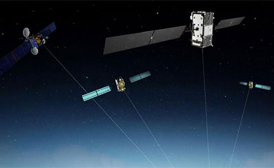
Following a waiver by the U.S. Federal Communications Commission (FCC) of its rules in November 2018, in which it allowed devices in the United States to access signals transmitted by the Galileo Global Navigation System, leading U.S. manufacturers are preparing to roll-out Galileo on U.S. territory.
At a meeting on Nov. 15 last year, the US FCC granted in part a request from the European Commission for a waiver of the FCC rules so that devices in the United States may access specific signals transmitted by Galileo.
This decision means that consumers and industry in the U.S. are now able to access certain satellite signals from the Galileo system, which can be used in combination with the U.S. Global Positioning System (GPS). The improved availability, reliability, and resiliency offered by incorporating Galileo capability into devices is something that U.S. chip manufacturers are eager to pass on to their customers.
“This is an important market development opportunity for manufacturers in the U.S. The FCC ruling means that industry can now benefit from the use of Galileo signals. The added accuracy and robustness offered by multi-constellation and multi-frequency capability will be a key differentiator on the market,” said Carlo des Dorides, Executive Director of the European GNSS Agency (GSA).
“We are glad to see FCC supporting Broadcom’s dual frequency GNSS vision, for which the GPS and Galileo combination is key,” said Vijay Nagarajan, VP Marketing Wireless Connectivity and Communication Division at Broadcom. “We enabled the world’s first dual frequency GNSS phone in 2018 with the simple goal of providing accurate location to the consumer even amidst the skyscrapers in a busy downtown. We are certain that consumers will benefit from this FCC ruling that will further drive the adoption of dual frequency GNSS.”
“As a leader in developing cellular technology — today, as the world launches 5G and dating back to Qualcomm’s legacy in 4G, 3G and 2G — including work to incorporate robust navigation solutions for smartphones, Qualcomm Technologies integrated Galileo across its chipset portfolio because we understand the importance and benefits of accurate, reliable, and rapid position location for consumers,” said Dean Brenner, senior vice president of Spectrum Strategy and Tech Policy, Qualcomm Incorporated. “We’re excited about the FCC allowing access to Galileo signals in the U.S. for commercial Location Based Services because it is a big step forward in improving the user experience, particularly in dense urban environments.”
Activating Galileo in the U.S.
Both Broadcom and Qualcomm Technologies, Inc. already have dual-frequency solutions that support Galileo E1/E5a signals: the world’s first dual frequency GNSS smartphone, the Xiaomi Mi-8, was fitted with a Broadcom BCM47755 chip and, in December, Qualcomm Technologies launched the newest generation in its 8 Mobile Platform Series, the dual-frequency Qualcomm Snapdragon 855 Mobile Platform.
“Approximately 100 smartphone models are already fitted with chipsets from these two manufacturers. Following the FCC ruling, we are expecting to see a significant increase in Galileo users coming from the U.S.,” said Justyna Redelkiewicz Musial, in charge of LBS and IoT market development at the GSA.
Better positioning and navigation
The FCC ruling permits access to two Galileo signals — the E1 signal that is transmitted in the 1559-1591 MHz portion of the 1559-1610 MHz Radio-navigation-Satellite Service (RNSS) frequency band and the E5 signal that is transmitted in the 1164-1219 MHz portion of the 1164-1215 MHz and 1215-1240 MHz RNSS bands.
Access to multi-constellation and multi-frequency capability means that users in the U.S. will be able to benefit from a better positioning and navigation experience particularly in urban environments where the unique shape of the E5/L5 signal makes it easier to distinguish real signals from the ones reflected by buildings, reducing the multipath effect. The simultaneous use of E5/L5 frequencies also mitigates other sources of error, such as ionospheric distortions, and makes the signal more robust against interference and jamming.
A self-driving tractor using the BeiDou Navigation Satellite System (BDS) was tested successfully March 10 in northwestern Tunisia, according to China.org.cn.
The representatives of China-Arab BDS/GNSS center and the Arab Information and Communication Technologies Organization (AICTO), as well as the academic staff of an engineering school in Mjez El-Beb region in northwestern Tunisia, attended the test ceremony.
The smart tractor, used in various agricultural activities, was equipped with a BDS receiver so that it could be controlled remotely without a driver.
“I am very impressed and surprised by the quality of the equipment offered by BeiDou,” said Sami Trimech, the strategic planning and development director at AICTO.
“We had a dream to bring BeiDou to the Arab countries,” said Nour Laabidi, the project manager at AICTO and head of China-Arab BDS/GNSS center in Tunisia.
“This is a pilot project. We are happy to implement it in our country and I hope that all Arab countries will be able to use this Chinese technology,” Laabidi said.
Hassan Kherroubi, a specialist in the mechanical industry at the Mjez El-Beb engineering school, stressed the contribution of this Chinese technology to the agricultural sector in Tunisia.
Agricultural activities, including harvest, will be more profitable and more effective with such technologies, according to Kherroubi.
“Our main concern is to benefit all Arab and African countries of this fruitful cooperation between Tunisia and China,” Kherroubi said, adding that this advanced technology will bring a bright future to the region.
BDS is compatible with other navigation systems, such as GPS, and users can receive services from both systems at the same time, improving positioning accuracy.
As a risk reduction effort for the U.S. Air Force’s GPS III Follow On (GPS IIIF) satellite program, Frequency Electronics Inc. has received a contract from Lockheed Martin Space, valued at $5.9 million, for the qualification of FEI’s Digital Rubidium Atomic Frequency Standard (DRAFS).
The contract’s intent is to qualify FEI’s DRAFS for potential use on the new GPS IIIF satellites, securing the industrial base for high-accuracy GPS atomic clocks.
To help the Air Force modernize its GPS satellite constellation with new technology and capabilities, Lockheed Martin Space designed and built the most powerful GPS satellite, GPS III. With 10 satellites under contract, in 2018, the Air Force selected Lockheed Martin to build up to 22 additional GPS IIIF satellites, adding new features and resiliency to the flexible satellite design. The Air Force began launching GPS III satellites in December 2018. Today, more than 4 billion users rely on GPS.
“We are extremely pleased to be awarded this contract and the opportunity to play a significant role in the GPS IIIF program,” Stanton Sloane, FEI’s CEO commented. “This award is the culmination of 50+ years of research and development of advanced quartz and atomic clocks based on FEI’s proprietary technologies. We are also pleased to continue our long-standing relationship with Lockheed Martin Space on critical national security programs.”
Martin Bloch, FEI’s Executive Chairman added, “I congratulate the FEI team on the development of this digital Rubidium clock for GPS IIIF program. FEI will continue the development of advanced clock technologies for future generations of Satellites and Terrestrial applications.”
Frequency Electronics designs, develops and manufactures high-precision timing, frequency control and synchronization products for space and terrestrial applications. Its products are used in satellite payloads and in other commercial, government and military systems including C4ISR and EW markets, missiles, UAVs, aircraft, GPS, secure radios, energy exploration and wireline and wireless communication networks.
Its subsidiaries and affiliates include FEI-Zyfer, which provides GPS and secure timing (“SAASM”) capabilities for critical military and commercial applications; and FEI-Elcom Tech, which provides subsystems for the Electronic Warfare markets and added resources for RF microwave products.
Norway has electronic proof that Russian forces disrupted GPS signals during recent NATO war games, according to a report in Reuters news service.
The Scandinavian country and North Atlantic Treaty Organization (NATO) member has demanded an explanation from its neighbor. “We recognize Russia’s right to exercise and train its capacities [but] it is not acceptable that this kind of activity affects security in Norwegian air space,” stated the Norwegian defense ministry.
Finland and Norway published claims in November that Russia may have intentionally disrupted GPS signals before and during NATO military exercises. The radio-frequency interference also affected the navigation of civilian air traffic in the Arctic. Both countries protested to Russia, which dismissed the allegations.
“We gave them the proof,” Norwegian Defence Minister Frank Bakke-Jensen stated publicly. Russia demurred, with Foreign Minister Sergey Lavrov terming the Norwegian allegations “a fantasy,” and said it would conducts its own investigation. “To be a neighbor of Russia you need to be patient,” added Bakke-Jensen.
Could Russia have targeted Norway intentionally? The minister replied: “They were exercising very close to the border and they knew this will affect areas on the other side.”
November saw NATO’s largest exercise in decades, involving forces from 31 countries in an area stretching from the Baltic Sea to Iceland.
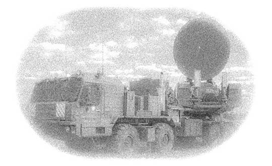
Above: Krasukha jammer mounted on a heavy-duty truck, part of the radio electronic warfare unit (EW) of the Western Military District. (Photo: Ministry of Defense of the Russian Federation)
Less than three weeks after its launch, the first GPS III satellite, SVN74, started transmitting navigation signals. SVN74 uses the pseudorandom noise (PRN) code number G04 previously used by the almost 25-year-old Block IIA satellite SVN36. The L1 C/A, L1 P(Y), and L2 P(Y) signals of SVN74 have been tracked since Jan. 9 at 00:01 UTC. Activation of the L2C and L5 signals followed on the same day at 19:43 UTC. Transmission of the legacy navigation message (LNAV) started Jan. 9, but the satellite is still marked unhealthy for ongoing on-orbit check out and testing.
Also, SVN74 is the first GPS satellite to transmit a new civil signal on the L1 frequency (1575.42 MHz), namely L1C, which was initially activated on the same day as the other SVN74 signals. Incidentally, the L1C signal was already being transmitted by the four satellites of the Japanese Quasi-Zenith Satellite System (QZSS).
Compared to the L1 C/A PRN codes, the L1C codes are 10 times longer (10,230 chips), reducing interference when multiple satellites are tracked by a receiver on the same frequency. Like L2C and L5, the L1C signal consists of a dataless pilot component and the data component with navigation data. Dataless signals enable more robust tracking under difficult conditions. For the L1C signal, 75 percent of its power is put into the pilot component.
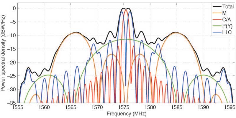
The theoretical spectra of the four signals transmitted on L1 by SVN74, namely the civil C/A-code and L1C, as well as the military P(Y)-code and M-code, are shown in FIGURE 1 along with the the total (summed) spectrum.
Figure 1. Theoretical spectra of the four signals transmitted by a GPS III satellite in the L1 frequency band. (Image: Authors)
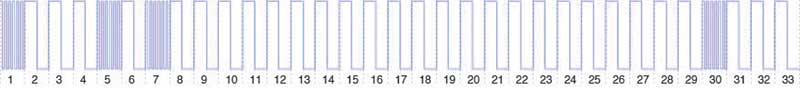
BOC. To achieve compatibility with the L1 C/A-code signal at the same center frequency, a binary offset carrier (BOC) modulation is used for spectral separation of L1C from L1 C/A. A BOC(n,m) signal is characterized by the fundamental frequency of the square wave subcarrier expressed in multiples n of the basic frequency of 1.023 MHz and the chipping rate expressed in multiples m of 1.023 megachips per second. A BOC(1,1) modulation is used for the L1C data component. For the pilot component, a time-multiplexed binary offset carrier (TMBOC) is used. The spreading waveform, with a length of 33 symbols, consists of four BOC(6,1) and 29 BOC(1,1) symbols as illustrated in FIGURE 2 resulting in a TMBOC(6,1,4/33) signal. The additional BOC(6,1) component allows for improved multipath mitigation.
Figure 2. Spreading symbols for the L1C pilot component: time-multiplexed BOC consisting of BOC(6,1) for the 1st, 5th, 7th and 30th symbols and BOC(1,1) for the other symbols. (Image: Authors)
Similar to GPS L1C, the European Galileo and the Chinese BeiDou-3 systems employ multiplexed BOC signals with BOC(1,1) and BOC(6,1) components in the L1 frequency band. A composite BOC (CBOC) modulation has been adopted for the Galileo E1 open service signal, which uses a weighted sum of the BOC(1,1) and BOC(6,1) components in both the data and the pilot channels. For the BeiDou B1C signal, BOC(1,1) is used for the data channel, while a quadrature multiplexed BOC modulation, QMBOC(6,1,4/33), with BOC(1,1) and BOC(6,1) subcarriers in phase quadrature, is used for the pilot channel.
Interoperability. The new civil L1 signals of GPS, Galileo and BeiDou show a high level of commonality and are specifically designed for full interoperability. This means that receivers can easily track signals of all three constellations and use the measurements to compute a combined multi-GNSS position solution. Aside from the similar signal modulations, the interoperability is further supported by the transmission of inter-system timing biases (such as the GPS-Galileo Time Offset) in the navigation messages.
The binary phase shift keying (BPSK) modulation of the C/A-code with a 1.023-MHz chipping rate introduces a main lobe at the center frequency of 1575.42 MHz and numerous side lobes with decreasing amplitude. The 10.23-MHz BPSK signal of the P(Y)-code is visible in Figure 1 as a broad peak at the center frequency and first side lobes at about 1560 and 1590 MHz. The M-code is characterized by its main lobes ±10.23 MHz from the center frequency due to its BOC(10,5) modulation. Finally, the L1C signal can be recognized as two narrow peaks separated by ±1.023 MHz from the L1 center frequency related to the BOC(1,1) modulation and two peaks at ±6.138 MHz related to the BOC(6,1) modulation. Side lobes of the BOC(1,1) signal are visible next to the main lobes at integer multiples of 2 × 1.023 MHz.
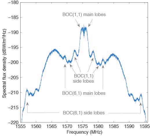
Observations. The German Aerospace Center (DLR) operates a 30-meter dish antenna at its ground station in Weilheim, near Munich, Germany. FIGURE 3 shows the L1 spectrum of SVN74 measured on January 15, 2019. One can clearly see the L1C BOC(1,1) main lobes at 1574 and 1576 MHz as well as the BOC(6,1) main lobes at 1569 and 1581 MHz. Selected side lobes are also indicated.
Figure 3. SVN74 L1 spectral flux density measured with the Weilheim 30-meter antenna on January 15, 2019, at 08:04 UTC. Selected features of the L1C signal are indicated by arrows. (Image: Authors)
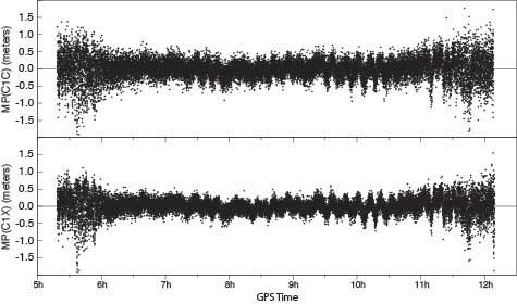
Initially, none of the International GNSS Service network receivers could track the L1C live signal of SVN74, but dedicated firmware versions supporting L1C tracking were soon made available by selected manufacturers. FIGURE 4 shows the multipath linear combination for the L1 C/A-code and the L1C signal tracked with a Javad TRE-G3TH receiver. Reduced measurement noise (multipath plus receiver measurement noise) of the L1C signal can be seen over all elevation angles ranging from about 3 to 83 degrees. (Tracking of the pass began at 4.3 degrees and ended at 3.0 degrees.)
Figure 4, Multipath linear combination (L1 pseudorange and L1 and L2 carrier phase) of the SVN74 L1 C/A-code (top) and L1C signal (bottom) from 1-Hz data of February 3, 2019, tracked with a Javad TRE-G3TH receiver at the Geodetic Observatory Wettzell. (Image: Authors)
The overall root-mean-square noise of the SVN74 pass shown in Figure 4 is 32 centimeters for the L1 C/A-code signal and 24 centimeters for L1C, that is, a reduction of 25 percent for L1C. Compared to the BPSK modulation of the legacy C/A-code signal, the increased steepness of the TMBOC correlation function offers lower measurement noise for the L1C tracking. In addition, the sensitivity to multipath is reduced.
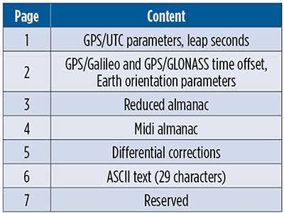
CNAV-2. Together with L1C, the second version of the civil navigation message, namely CNAV-2, is being transmitted. CNAV-2 is composed of three subframes: subframe 1 contains information about the current epoch. Subframe 2 comprises clock and ephemeris data including inter-signal corrections (ISCs). ISCs provide clock corrections for single-frequency users and dual-frequency users utilizing signals other than L1 P(Y) and L2 P(Y). Whereas the essential broadcast ephemeris data in subframe 2 repeat continuously over the validity period of typically two hours, subframe 3 contains pages with alternating content as listed in TABLE 1 (page 41).
Table 1 Currently defined pages of the CNAV-2 subframe 3.
Despite a different message layout, most CNAV-2 parameters and their values match those transmitted in the CNAV message of the L2C and L5 signals. Additional parameters comprise the ISCs for the L1C signal. Compared to the LNAV legacy navigation message, CNAV and CNAV-2 utilize an extended set of ephemeris parameters that allow for a smoother orbit representation compared to LNAV. Multi-GNSS applications benefit from the GPS/GNSS time offset (GGTO) parameters included in page 2. In the same page, Earth orientation parameters are provided that are relevant for users of an inertial frame, such as for spaceborne navigation. The CNAV-2 repeat cycle of 18 seconds allows for a faster access to broadcast ephemerides included in subframe 2 compared to LNAV. Compared to CNAV, CNAV-2 furthermore provides a more sophisticated error detection and correction scheme.
As of the beginning of February 2019, only pages 1, 2 and 4 of CNAV-2 subframe 3 are being used. Within a cycle of 144 seconds, page 1, page 2 and six sets of page 4 midi almanac data (each for one individual satellite) are transmitted. The full almanac for 32 satellites is thus transferred in an average of about 13 minutes. The content in these subframes corresponds to that in L2 and L5 CNAV messages. Updates of CNAV-2 are performed in two-hour intervals starting at 01:30. This is the same update scheme as for CNAV but different from LNAV where the two-hour intervals start at 00:00.
Note that some time will pass before enough GPS III satellites are transmitting so that users can fully enjoy the benefits of the new L1C signal.
MANUFACTURERS
Spectral measurements at the Weilheim 30-meter antenna were made with a Rohde & Schwarz FSQ26 vector signal analyzer. Receiver measurements have been collected with a JAVAD GNSS TRE-G3TH receiver running an L1C-capable firmware version.
PETER STEIGENBERGER and OLIVER MONTENBRUCK are scientists at the German Space Operations Center of the German Aerospace Center (DLR). STEFFEN THOELERT is an electrical engineer at DLR’s Institute of Communications and Navigation. RICHARD B. LANGLEY is a professor at the University of New Brunswick and editor of the Innovation column for GPS World magazine.
3.1415926…. π. Every nerd’s favorite number. It is the ratio of a circle’s circumference to its diameter in conventional or Euclidean space. We use it, for example, to convert angles measured in radians to degrees (π radians = 180 degrees). π is an irrational number, which means that its value cannot be expressed exactly as a fraction m/n, where m and n are integers. Consequently, its decimal representation never ends or repeats. But we sometimes use an easily remembered fraction, such as 22/7, to get an approximate value. In this case, 3.14. But, if we compute more digits with this fraction, we get 3.1428571…, clearly an incorrect result. A better way to remember π to eight digits is to count the number of letters in each word of the mnemonic “May I have a large container of coffee?”
In computations related to GPS, how many digits of π should be used? It depends. If you are developing your own algorithms and software for modeling GPS observations or determining precise orbits for the satellites, you’ll likely need π to 16 digits for double-precision floating-point calculations. But it would be a mistake to use π to this precision in computing the position of a satellite from the broadcast ephemeris. The GPS interface specification document, IS-GPS-200, specifies a 14-digit value for π (3.1415926535898) in the satellite coordinate computation. Use fewer or more digits, and the resulting satellite coordinates will not be as accurate.
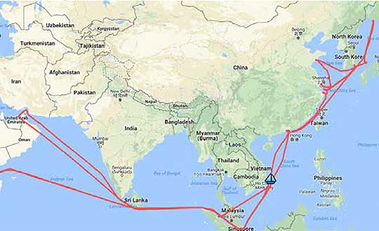
A year-long project aboard a commercial cargo ship collected tens of thousands of snapshots of radio-frequency interference in the GNSS band on a passage from Spain to Korea and back. Most interference was detected in busy port areas, less interference while transiting along coasts, and while least frequent, interference was still found in the open ocean.
Researchers at the German Aerospace Center (DLR) are still analyzing the vast amount of GNSS disruption data collected during the year-long project. Two papers have already been published about this project, and more are on the way, according to principle researcher Emilio Pérez Marcos.
In a paper presented at the Institute of Navigation last year, Marcos and his co-authors outlined the results of the last five months of this unique sampling experiment. Detection equipment was mounted on a large Hapag-Lloyd container ship. The antenna was mounted about 50 meters above the water line and provided a line-of-sight of 25km or more. The L1/E1 and L5/E5a frequency bands were continuously monitored. In addition to a “Snapshot” recording device used to save raw data samples (time snapshots), a more resilient DLR multi-antenna receiver was used to assess the impact of interferences in beamforming array GNSS receivers (semi-resilient).
As might be expected, the most interference was detected in busy port areas. Less interference was experienced while transiting along coasts. While it was the least frequent, interference was still detected during open ocean transits.
Table: Emilio Pérez Marcos and co-authors
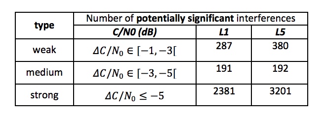
Of the 39,045 snapshots recorded, 6,632 contained radio frequency interference at 1dB or higher. Separate tests have shown that many single antenna GNSS receivers begin to perform poorly with interference signals greater than 1dB. The other 32,413 snapshots could represent interference signals that may have come from weaker transmitters, sources more distant from the ship, been the result of adjacent band transmissions, or other phenomena.
Three particularly strong and persistent interference incidents were noted in the paper.
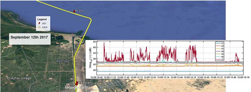
The first was detected when the vessel was transiting the Suez Canal northbound. The interference lasted around five hours and 60km. At several points the interference prevented the DLR semi-resilient GNSS receiver from working properly, which would mean that any single antenna GNSS receiver would cease to function completely.
Vessel going north in Suez Canal. RFI detectable during approx. 60 km. Inset: Eigenvalues during the 5 hours that the RFI was detectable. (Graphic: Emilio Pérez Marcos)
The second caused the DLR receiver to fail when the vessel was entering Jebel Ali, the port of Dubai in the United Arab Emirates. The DLR receiver provided some resilience thanks to its beamforming capabilities; again any other receiver would have suffered the interference effects earlier being unable to provide any PVT. The receiver did not return to proper operation for 11 days and 5,000km. The reason for this is uncertain and under investigation.
Particularly strong interference (45dB) caused the third incident and resulted in the DLR receiver failing for three days. It began when the ship was entered the highly trafficked Malacca Straits.
The equipment used also allowed researchers to determine direction of arrival for the interfering signals and to evaluate whether the interference was a spoofing signal.
For the reported strong interference events, DLR consulted the captain of the ship, who attested and confirmed the loss of PVT in the ship’s own GNSS receiver, with all the consequences that this implies for the systems that rely on it.
The paper, “Interference and Spoofing Detection for GNSS Maritime Applications,” was presented at the ION GNSS+ conference in Miami in September of 2018. It described the last phase of a yearlong measurement effort aboard the ship by DLR. An earlier phase of the campaign has also been published in E. P. Marcos et al., “Interference awareness and characterization for GNSS maritime applications,” 2018 IEEE/ION Position, Location and Navigation Symposium (PLANS), Monterey, CA, 2018.
The authors are preparing additional papers to describe more of the results from the larger project.
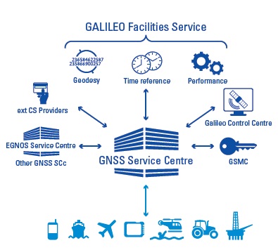
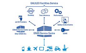
Responsibility for in-depth troubleshooting and problem resolution of the GSC Ground Infrastructure has been transferred from a European GNSS Agency (GSA)-held European GNSS Service Centre (GSC) infrastructure contract to Spaceopal and its core team member DLR GfR, responsible in the Galileo Service Operator (GSOp) industrial organization also for L2/L3 maintenance activity. This contract extends for 10 years.
The transfer occurred after Spaceopal successfully passed the Maintenance Handover Review (MHOR) for the Level 2 and 3 Maintenance of the GSC in Torrejón de Ardoz, outside Madrid, Spain.
“Taking over this responsibility will allow us to react much quicker to anomalies in a more flexible way, directly improving operations and the service that the European GNSS Agency (GSA) provides to the Galileo end users,” said Christian Hessmann, Engineering Manager at Spaceopal.
The GSC services can be accessed by Galileo users via the GSC web portal.
Spaceopal is a joint venture between DLR Gesellschaft für Raumfahrtanwendungen (GfR) mbH, a full subsidiary of the German Aerospace Center (Deutsches Zentrum für Luft- und Raumfahrt; DLR), and the Italian firm Telespazio S.p.A. Both parties contribute their respective Galileo Control Centers in Oberpfaffenhofen and Fucino.
Since July 2017, Spaceopal GmbH has operated the Galileo satellite fleet under the GSOp contract and will thus ensure the provision of the Galileo services to the worldwide community.
The GSC provides the single interface between the Galileo system and the users of the Galileo Open Service (OS), and the Galileo Commercial Service (CS) for the provision of specific services beyond the Galileo Signal-In-Space (SIS) transmitted by the operational satellites. The GSC acts as an active means to engage in “in”- and “out” bound activities and is conceived as a centre of expertise, knowledge sharing, custom performance assessment, information dissemination and support to the provision of value-added services enabled by the Galileo OS and CS core services.
The GSC is located in a fully secured environment in Madrid, Spain, within the National Institute of Aerospace Technologies (INTA) facilities at Torrejón de Ardoz, overseen by the Spanish Ministry of Defence.
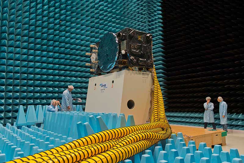
Inside the ESTEC Test Center, Galileo’s First Operational Capability first flight model, FM1, prepares for passive intermodulation testing in the Maxwell electromagnetic facility. (Photo: ESA-Anneke Le Floc’h)
Gazing through soaring plexiglass walls at the space simulation room of the European Space Agency’s Test Center in the Netherlands affords a glimpse into scientific history.
I felt a frisson, a highly regimented frisson if you will, of vicarious thrill for the rigors, rhythms and methods of research and testing as I toured the center after giving a keynote at the agency’s Navigation Days. Here, the final birthing touches were administered to transmitters beaming forth the Second Golden Age of satellite-based navigation.
One can debate which constellation combination will prove most fruitful to users: GPS plus GLONASS, GPS plus BeiDou, GPS plus Galileo (note the common term). I believe it will be the last, because of the close synergy and symbiosis of the two commercial arenas, North America and Europe.
All Galileo Full Operational Capability (FOC) satellites had their mettle and metals probed, radiated, bombarded, shaken and shocked here before they journeyed to space. The test center’s role is to verify, intensively and for months per satellite, that it can perform well for the whole of its planned lifetime.
A mass property test checks that the center of gravity and mass are aligned within design specifications, so that the satellite’s orientation can be accurately and economically controlled with thruster firings in orbit, prolonging work life by conserving propellant.
A five-week thermal-vacuum test runs inside a 4.5-meter diameter stainless steel vacuum chamber, the Phenix. An inner thermal tent heats to simulate solar radiation and cools with liquid nitrogen to create the chill of sunless space.
In the Maxwell test chamber, spiky radio-absorbent anechoic walls test electromagnetic compatibility to ensure that all systems operate together without interference. Noise horns generate more than 140 decibels to simulate a violent launch. A quad shaker table vibrates the satellite up, sideways and down, as accelerometers search for hazardous internal vibration, gathering data across hundreds of channels.
Altogether a severe trial, a crucible from which the FOC satellites emerge certified and ready for space.
Oh, that we humans were similarly tested before placement in positions of power.
A Chinese cargo ship, the Rongda Changsha, equipped with receivers downloading signals from the BeiDou Navigation Satellite System (BDS), arrived at Brunei, on the north coast of the island of Borneo in Southeast Asia, in February after embarking from Luojing Port in Shanghai. This marks the first public successful application of BeiDou terminal products in the South China Sea and unveils China’s ambition to promote BeiDou products in the international marketplace.
The Shanghai-Brunei trip was a trial for not only examining BeiDou-3’s capacity, but for learning the users’ experience and needs. The data collected from the trip has been analyzed and applied for updating and prioritizing the marine navigation system, according to China Aerospace Science and Technology Corporation (CASC), manufacturer of the Beidou receivers on the ship.
It is anticipated that more services will soon arrive, with Internet and voice calls facilitated by the messaging aspect of BDS, for further exploring industrial application scenarios and — importantly for government support of its GNSS — protecting Chinese outbound and inbound routes. The South China Sea is one of the world’s busiest waterways, and oil imports to China from the Middle East are a key strategic component of this traffic activity.
BDS now covers more than 50 countries and more than 3 billion people. BDS-related products have gained access to the markets of more than 70 countries and regions, more than 30 of which are along the (land-based) Belt and (maritime) Road, in line with the Belt and Road Initiative. Through joint applications with other compatible navigation satellite systems, BDS provides global users with diversified choices for better application experience.
“Chinese security interests encompass not only China itself and nearby areas, but also the sea lanes that enable the import of raw materials and export of finished goods,” wrote Scott Pace in GPS World, December 2010. “In recent years, China has shown an increasing interest in ‘maritime domain awareness,’ in which satellite navigation is used for monitoring the transit of ships in the Indian Ocean (for example, oil from the Middle East) and the South China Sea (minerals from Australia, fishing zones). Satellite navigation is a dual-use, commercial and military, interest for China, and this may have prompted support for the more advanced, independent GNSS that would become Beidou-2 or Compass.”
Pace was chosen by the White House to serve as executive secretary of the National Space Council in July 2017. Pace is also director of the Space Policy Institute and Professor of Practice of International Affairs at George Washington University. He serves as a special counselor to the National Space-Based Positioning, Navigation and Timing (PNT) Advisory Board.
Capt. Adam Moody, 2 SOPS GPS Operations Support flight commander, and Staff Sgt. Carl Ellinger, 2 SOPS GPS mission chief, review a checklist of procedures for a transfer operation at Schriever Air Force Base. (Photo: U.S. Air Force photo/Dennis Rogers)
The 2nd Space Operations Squadron (2 SOPS), based at Schriever Air Force Base, will implement the GPS Issue of Data, Clock software modification this summer in accordance with established guidance, according to Rick Hamilton, CGSIC Executive Secretariat, U.S. Coast Guard Navigation Center.
The modification is in compliance with GPS Interface Specifications IS-GPS-200, which is published for manufacturers to ensure continued device compatibility.
As the largest Department of Defense spacecraft constellation, operators must modify processes, software and operations to meet the ever-growing demand for GPS signals. The squadron conducts software modifications regularly to support the constellation.
The modifications are primarily transparent to users, specifically those with IS-GPS-200 compliant devices. Users who experience issues with their devices or receivers should contact the manufacturer to troubleshoot the problem.
The U.S. Coast Guard Navigation Center provides information and services to civil GPS users. They can be contacted at 703-313-5900 or online.
Oregon Department of Transportation workers use DT Research’s GNSS rugged tablets. (Photo: DT Research).
The Oregon Department of Transportation (ODOT) has expanded its use of DT Research GNSS rugged tablets to all 15 of its construction management offices across the state, and also use the tablets for biology, geology, roadway and wetland projects.
DT Research worked closely with ODOT to design purpose-built rugged tablets that empower state workers to easily collect and transmit geospatial measurements in the field using GNSS real-time kinematic (RTK) technologies.
“DT Research’s GNSS rugged tablets have enabled us to bring high-accuracy geospatial measurements to workers across the Department of Transportation, which has literally changed the way we work,” said Chris Pucci, construction automation surveyor at ODOT. “The tablets have enabled us to save time, reduce costs and improve the accuracy of projects through ‘digital-as constructed’ measurements and real time data capture.”
The tablets have a dual-frequency GNSS module built in, which provides stand-alone sub-meter accuracy to centimeter-level accuracy with RTK from GPS, GLONASS and Galileo satellites.
The tablets are compatible with existing survey and GIS software for mapping applications and provide an advanced workflow for data capture, accurate positioning and data transmitting.
“We now have essentially created one-person survey crews because the DT Research tablets are so much easier to use than a tape measure and paper to accurately calculate and record measurements during complex construction projects,” Pucci said. “Using the tablets saves us an average of $2,000 for every survey-grade measurement job that does not require a full survey crew.”
“In addition, the tablets have provided us with a contract verification system by having highly accurate digital-as-constructed measurements that are delivered immediately and stored forever, which saves the state time and money by avoiding independent re-measurement checks due to billing discrepancies at the end of a project,” added Pucci.
The DT Research GNSS tablets can store up to 1 Terabyte of data for field data collecting. Users can avoid down time with a high-capacity hot-swappable battery pack, which delivers 60 or 90 watts for up to 15 hours of continuous mobile communications. The units include Long Range Class 1 Bluetooth, which powers wireless connectivity up to 1,000 feet and 4G mobile broadband.
“The simplicity of how the DT Research tablets work is amazing,” Pucci said. “Unlike complex professional survey equipment, the DT Research tablets are a Windows-based mobile device with a user interface that is familiar to workers. In just two hours, I can easily train state workers with diverse skill sets to measure quantity, linear features and volumes for a variety of projects — and they are ready to go.”
The tablets run on Microsoft Windows 7 Professional or Windows 10 IoT Enterprise and are high performance devices with an Intel 6th or 8th Generation Core i5 or i7 processor. The rugged tablet is designed for outdoor use with a brilliant LED-backlight, 800 nits sunlight-readable screen and capacitive touch.
“We have found the DT Research tablets to be incredibility easy to manage and highly durable — we just turn them on and they work,” said Pucci. “In the three years that we have used the tablets, we have had very few technical support questions and they hold up well in different weather conditions. There isn’t a comparable product on the market at the price point.”
The DT Research tablets are military-grade durable devices, yet lightweight, offering the versatility to be used in field-to-office settings. For use in harsh environments, the tablet is fully ruggedized to meet the highest durability standards with an IP65 rating, MIL-STD-810G for vibration and shock resistance and MIL-STD-461F for EMI and EMC tolerance.
For use in a variety of environments, the tablets are complemented by many accessories including: external antennas, pole mount cradles, detachable keyboards, battery charging kits and digital pens.