Category: Survey

  • Accuracy, Datums, and Geospatial Data and other Updates

    Plus GLONASS Update

    If you were able to attend the webinar “Nightmare on GIS Street: GNSS Accuracy, Datums and Geospatial Data” held on June 20, thanks for attending. If not, you can view the webinar here. We had a world-class panel of experts discussing the nightmare of accurately combining different sources of geospatial data as well as on-the-fly datum transformations in the field when using high-precision GPS/GNSS receivers.

    Let me apologize in advance if it seems like I’m “beating a dead horse” in writing about this issue. I intended to address the questions raised during the webinar. After addressing one of the first issues below (WGS-84), I expended my allocated space and energy. Rest assured I will publish answers to the other questions that were raised before and during the webinar.

    Very few of the geospatial software vendors (GIS or surveying) are handling horizontal datum transformations correctly or in a manner that is easy for the average GIS operator to understand. The good news is that hopefully we’re raising awareness and some are responding, such as Carlson Software. Carlson recently released version 3.0 of their SurvCE surveying software for GNSS data collection. It includes a 14-parameter transformation from ITRF08/WGS-84 G1674 to NAD83/2011. You might want to watch the four minute video below demonstrating the transformation process in SurvCE 3.0. You’ll see the difference after the transformation is about two tenths of a foot (~6cm). If I were to guess, I would say majority of the difference after the transformation is the tectonic plate movement that is unaccounted for. Reconciling the tectonic plate movement is difficult because you need to have an accurate velocity (movement) model for the software to reference. In some geographic areas, the movement is minor (1mm per year) while other geographic regions move 6cm per year or more. Lastly, what if there’s a major earthquake such as the 2011 earthquake off the coast of Japan or the 2010 earthquake off the coast of Chile. During those events, the ground shifted many meters in some cases.

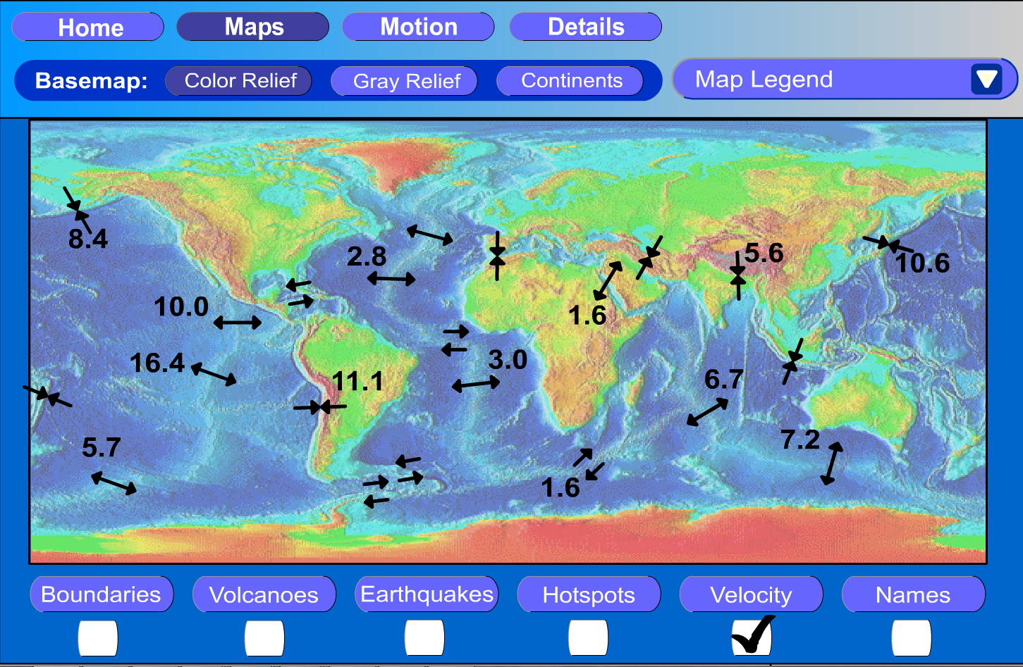
    Just a reminder from my last article on this issue in Geospatial Solutions, here’s a rough tectonic plate velocity model from the University of Kentucky:

    TectonicUKY
    Source: Michael Dennis – US National Geodetic Survey

    I’d like to spend a little time on the subject of the WGS-84 reference frame. It’s a term that’s used and abused a lot, including by myself on occasion.

    Taking a Look at the WGS-84 Reference Frame

    First, let me begin with the statement that WGS-84 should not be in your geospatial vocabulary. In fact, I’ve been corrected in the past that it is actually a reference frame rather than a datum, but you’ll likely see it listed as a datum in your geospatial software.

    WGS-84 is not something you’ll find physical marks on the ground that you can use to verify GNSS equipment performance. WGS-84  is defined by the U.S. National Geospatial-Intelligence Agency (NGA), which serves the U.S. Department of Defense and the U.S. Intelligence Community. In other words, one of its roles doesn’t include serving the civilian community. Originally, the accuracy of data referenced to WGS-84 could not be defined more accurately than a couple of meters. In fact, the definition of WGS-84 has changed several times over the years, usually without your knowledge, and usually not accounted for in the geospatial software you are using.

    Originally (1987), the Department of Defense transformation values between WGS-84 and NAD83 (dX, dY, dZ) were set to 0, which led people to believe they were considered the same. A footnote that was largely ignored is that the standard deviation of the WGS-84 to NAD83 transformation values was ~2 meters (Doyle, D., 2013 email). The bottom line is that if someone hands you a GIS dataset and says it’s referenced to WGS-84, an alarm should immediately sound in your brain prompting you to query the presenter of the data. When and how was the data referenced to WGS-84? Likely, they won’t know the answers to the questions you ask. In that case, you have no choice but to tag the data as only accurate to two meters, at the very best. Of course, if it was data collected by a consumer-grade GPS unit, the accuracy is likely much worse.

    The history of WGS-84 is as follows:

    ——————————————————–

    WGS-84 (Original) – 1987

    Aligned with NAD83/86 (original) but standard deviation of the transformation was +/- 2 meters.

    ——————————————————–

    WGS-84 (G730) – 1994

    Aligned with ITRF91 (epoch date 1994.0). A significant shift took place with this adjustment.

    ——————————————————-

    WGS-84 (G873) – 1996

    Aligned with ITRF97 (epoch date 1997.0)

    ——————————————————-

    WGS-84 (G1150) – 2002

    Aligned with ITRF00 (epoch date 2001.0)

    ——————————————————-

    WGS-84 (G1674) – 2012

    Aligned with ITRF08 (epoch date 2005.0)

    ——————————————————-

    As you can see from above, if someone hands you a dataset and states it’s in WGS-84 format, it begs the question of “which one?”, not unlike the same question you should ask if someone states a dataset is “NAD83”

    As I mentioned above, while the 14-parameter transformation to move from one datum to another is not commonplace in geospatial software yet, but it’s gaining traction and it’s not difficult to implement. The trickier, and more difficult variable to reconcile is the tectonic plate movement. It may not seem like the earth you stand on is moving very much, but years of movement can add up when you’re using GNSS equipment capable of 1-2cm accuracy.

    Example: Let’s say you’re using OmniSTAR’s HP real-time correction service. The accuracy of that service is rated at 10cm horizontal 2DRMS. OmniSTAR informed me that their system is referenced to ITRF08 using the current epoch date (eg. the date you collect the data). Let’s say your GIS basemap is referenced to NAD83/2011 (epoch 2010.0), which is the most current version of NAD83 (I apologize to non-US readers for this example, but you likely have a similar situation). The 14-parameter transformation will transform your data from ITRF08 (current date epoch) to NAD83/2011 (current date epoch), but then you have to account for the tectonic plate movement from current epoch date (assume 2013.5) to 2010.0. That’s 3.5 years of crustal movement. The tectonic plate movement in some parts of the US are only 2mm/year so 3.5 years x 2mm/year = 7mm. Since OmniSTAR’s HP service is 10cm, you could say that 7mm of plate movement is below the noise floor. However, let’s say you’re in California where the tectonic plate movement is 5cm/year in some places. Reconciling the tectonic plate movement in that environment becomes important when you think about 3.5 years x 5cm/year = 17.5cm!

    So, when populating your GIS database, especially with “high-accuracy” data, it’s important to understand not only the datum the incoming data is referenced to, but also the epoch date the data is referenced to. An answer of “WGS-84” is not good enough and probably not accurately represented in the geospatial software you’re using. More than likely, ITRFxx is more accurately defined in your software, if it is present.

    Regardless, WGS-84 should not be in our geospatial vocabulary, or at least be quickly fading.

    By way of background, the ITRF (International Terrestrial Reference Frame) Center are funded by the Institut National de l’Information Géographique et Forestière (IGN), hosting the IERS ITRS Product Center, and partly by the Space Geodesy Research Group (GRGS).

    ————————————————————————————————————-

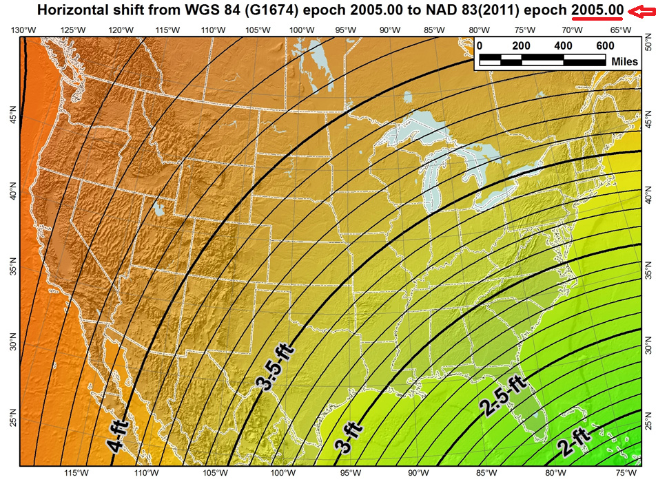
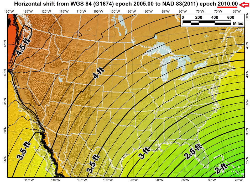
    To illustrate the effect of tectonic plate velocities, please view the following two images:

    The first image shows the the difference between the latest definitions of WGS-84 (G1674)/ITRF08 epoch 2005.0 and NAD83/2011 epoch 2005.0. Notice the smooth contour lines. This is using the 14-parameter transformation.

    Source: Michael Dennis - US National Geodetic Survey
    Source: Michael Dennis – US National Geodetic Survey

    However, the correct US definition of NAD83/2011 is referenced to epoch 2010.0, a full five years later than the first image where it was referenced to 2005.0. Notice the dramatic effect of the tectonic plate movement in the western part of the US. In this case, the 14-parameter transformation was used as well as the velocity model to estimate the tectonic plate movement.

    Source: Michael Dennis - US National Geodetic Survey
    Source: Michael Dennis – US National Geodetic Survey

    This illustrates that increasingly, geospatial data consumers will need to consider that “time is of the essence” when combining geospatial datasets.

    GLONASS Rocket Crash

    On July 2, 2013, a rocket carrying three GLONASS satellites crashed shortly after lifting off from its launch pad in Kazakhstan’s Baikonur cosmodrome. It’s the second launch crash for GLONASS, costing Russia six GLONASS satellites in the past three years. According to several sources, the cause of the July 2 crash was blamed on incorrectly installed angular velocity sensors. Despite the loss, GLONASS still has a full constellation of 24 satellites and, since GLONASS is largely used as an augmentation to GPS, people using GPS/GLONASS receivers should experience no change in performance.

    Rumors are circulating that this crash signals the beginning of the end of the GLONASS program, but I don’t believe it. Although this crash is a serious blow to Russia’s space program and will certainly set back the GLONASS program due to the nature of the crash (at the launch pad), I believe that GLONASS is here to stay.

    GPS suffered a major setback when, in 1986, the Space Shuttle Challenger exploded 73 seconds after lift-off because the space shuttle was the planned launch vehicle for GPS satellites. Subsequent launches were shifted to the Delta II rocket, causing a two-year delay in GPS satellite deployment. However, GPS never subsequently strayed from its course and for nearly three decades has been the so-called gold standard of satellite-based positioning, navigation, and timing.

    с надеждой (here’s hoping) GLONASS can similarly recover its momentum and progress as planned.

    Update: On July 9th, Ria Novosti reports that Russia will launch two GLONASS navigation satellites later this year to make up for the loss of three satellites in the recent Proton rocket explosion after launch from the Baikonur space center in Kazakhstan, according to a senior space industry official.

    “We are planning to launch two satellites from the Plesetsk space center [in northern Russia] to replenish the GLONASS orbital grouping following the recent Proton-M accident,” said Nikolai Testoyedov, the head of the Information Satellite Systems (ISS) company, which manufactures satellites for the GLONASS project.

    The first GLONASS is scheduled for launch in the beginning of September, and the second at the end of October, according to Testoyedov. The official added that both satellites will be launched on board the Soyuz carrier rockets, which has proven to be more reliable than ill-fated Protons.

    A group of 29 GLONASS satellites is currently in orbit, with 24 spacecraft in operation, three spares, one in maintenance, and one in test flight phase, according to Russia’s space agency, Roscosmos.

    Join me on the NSPS Radio Hour – Monday, July 22, 11:00am US Eastern Time/8:00am Pacific Time

    I, along with Michael Dennis of the US National Geodetic Survey, will be guests on the National Society of Professional Surveyors (NSPS) radio hour talking about interesting geospatial data and GNSS subjects. You can tune in live or download the mp3 audio recording onto your smartphone or mp3 player. Feel free to send me an email ahead of time if there’s a particular subject you’d like to hear us discuss.

    See you next time.

    Follow me on Twitter at https://twitter.com/GPSGIS_Eric

  • Two Products Added to NovAtel’s OEM6 Receiver Line

    Two Products Added to NovAtel’s OEM6 Receiver Line

    NovAtel has announced two new GNSS receivers: The OEM638 high precision receiver card and the ProPak6 enclosed receiver. The two products incorporate NovAtel’s most advanced GNSS technology, the company said.

    Novatel OEM638.
    Novatel OEM638. Photo: NovAtel

    The most advanced card within NovAtel’s OEM6 GNSS receiver family, the OEM638 tracks all existing and planned constellations including GPS, BeiDou, GLONASS, Galileo and QZSS. By providing flexible positioning options, from standalone meter-level to AdVanceRTK centimeter-level accuracy, the OEM638 offers the flexibility to meet a wide range of positioning requirements. A powerful API, 4-GB on-board data storage, wide input voltage and a host of interface options simplifies integration, decreasing time to market and overall system costs, NovAtel said.

    “With the addition of the OEM638 GNSS receiver card, NovAtel’s OEM6 product line offers an even wider range of positioning options on our standardized technology platform. With three compact form factors to choose from, the OEM6 product line gives us the ability to meet the unique size, weight and performance requirements of our customers,” said Jason Hamilton, director of marketing for NovAtel.

    The ProPak6 is NovAtel’s most sophisticated GNSS enclosure product, offering meter-level to centimeter-level positioning in a rugged, water resistant IP67 housing. Standardized software and hardware connections, including multiple RS-232/RS-422 serial ports, CAN Bus, USB host and device, as well as Bluetooth, Wi-Fi, and optional cellular radio, speeds time to market and maximizes user capabilities, the company said. The ProPak6 is designed for reference station, timing, and general position applications.

    NovAtel ProPak6. Photo: NovAtel
    NovAtel ProPak6. Photo: NovAtel

    “Our ProPak6 provides a powerful enclosure option for integrators looking for positioning flexibility, multiple communication options and Ethernet support for remote configuration and access of data logs,” Hamilton said. “It was designed to simplify the integration process, by accelerating time to market and ensuring maximum return on investment. ”

    The OEM638 and ProPak6 will be available to order July 26, with shipments beginning in August.

  • Select Energy Launches Real-Time Data Management for Water Sources

    Select Energy Launches Real-Time Data Management for Water Sources

    Proper management of large volumes of fluid has become a necessity as hydraulic fracturing has increased throughout North America. Creating the most effective fluid handling solution involves environmental, cost and project timeline considerations.

    Select Energy Services, LLC, has launched AquaView, a suite of services that efficiently monitor water at various stages of the project through real-time, wireless technology. AquaView’s instant monitoring capabilities allow Select to respond immediately to on-site issues before emergencies arise.

    AquaView capabilities include pit and reservoir hydrographic surveys utilizing SONAR remote control and GPS real-time data; data delivered to a secure portal offering current and historical data; real-time water quality reporting; and mapping and geographic information systems (GIS) support. The system can transmit the data with enabled access through computers, smartphones, tablets and text messages.

    “This new technology is changing the way our industry does business,” said John Schmitz, Select Energy Services CEO. “AquaView will reduce down time and assist in the maintenance of completion schedules, essentially removing the need for traditional water tracking and measurement systems.”

    Select’s team is capable of water transfer, containment assembly, water fill and complete removal or disposal.

  • Trimble Expands Mobile Spatial Imaging Portfolio

    Trimble-MX2-Spatial-Imaging-System[1].jpg Photo: Trimble
    Photo: Trimble
    Trimble has introduced the Trimble MX2 mobile spatial imaging data capture system. The MX2 extends the capabilities of geospatial professionals, allowing them to safely and effectively address complex projects by collecting spatial data from a mobile scanning platform, the company said. The Trimble MX2 provides a versatile and complimentary addition to Trimble’s family of mobile data capture systems.

    Designed for mapping, surveying and engineering environments, the MX2 is rugged, lightweight and portable. It is also easily deployed and redeployed on projects similar to conventional surveying equipment. A precise laser scanner, along with an embedded Trimble-Applanix GNSS/Inertial positioning system, allows geospatial professionals to create the point cloud accuracies necessary for many spatial imaging projects. Accompanied by Trimble Trident software to capture, process and analyze point data, the MX2 offers a ready-to-use workflow for surveyors and professionals in mapping, engineering, planning, oil and gas, utilities, mining, environmental, public safety and more. The system is available in single and dual-laser versions.

    In conjunction with the MX2 system, Trimble also announced new features for its Trident Software 6.0. The software developed for rapid transformation of point clouds and imagery into geospatial intelligence has been significantly enhanced to provide a scalable software suite for a wide range of users. Additions include the incorporation of direct trajectory import and the Trimble Coordinate System Manager. The Trimble Trident software suite is ideal for the analysis of mobile laser scanner data and geo-referenced imagery.

    “The Trimble MX2 provides survey companies with the opportunity to enter the world of mobile scanning at a time when it is becoming a desired service within their solution portfolios,” said Katherine Sandford, general manager of Trimble’s Imaging Division. “The MX2 offers a simple and highly productive mobile data collection capability and a 3D point cloud workflow for a wide range of users.”

  • Topcon Offers HiPer SR Integrated Receiver for GIS, Mapping

    Topcon Offers HiPer SR Integrated Receiver for GIS, Mapping

    HiPerSR_GIS_Topcon-W Photo: Topcon Positioning Systems
    Photo: Topcon Positioning Systems

    Topcon Positioning Systems has announced the HiPer SR integrated receiver for GIS and mapping applications.

    The HiPer SR for GIS is a compact, integrated GNSS receiver with sub-meter accuracy. Additional, scalable options are available via OAF (Options Authorization File) upgrades, delivering accuracy levels of sub-decimeter and centimeter without the need for additional hardware, Topcon said.

    The HiPer SR for GIS can be paired with a Topcon controller and eGIS software, or used with Topcon’s eGPS utility software to use with a third-party device and application such as ArcPad or ArcGIS mobile running on a Windows tablet or mobile device.

    “The HiPer SR for GIS brings the very finest in Topcon GNSS technology into a compact and rugged housing,” Jason Hooten, TPS sales manager for GIS, said. “Superior tracking and positioning is provided by the HiPer SR’s Vanguard receiver technology with advanced Fence Antenna.”

    “GIS field work is changing as more field workers are using various types of collection devices like smartphones, tablets, and laptops in addition to the traditional data collectors. Unfortunately, the GPS in these devices are not accurate enough for locating buried assets or doing initial inventory collection. The HiPer SR provides this accuracy regardless of job site demands,” Hooten said.

    HiPerSR_Topcon-W Photo: Topcon Positioning Systems
    Photo: Topcon Positioning Systems

    “The new HiPer SR is an adaptable device that can be used to locate utilities within an inch one day and the next provide sub-meter accuracy for an environmental study. This device provides accurate positioning to different applications as needed. The HiPer SR is small in size, but giant in performance and flexibility.”

  • GPS World, Geospatial Solutions Report from Esri Conferences

    GPS World, Geospatial Solutions Report from Esri Conferences

    Geospatial Solutions Editor Eric Gakstatter, who is also a contributing editor to GPS World magazine, will be attending the 2013 Esri Survey Summit and Esri International User Conference, providing continuous new and analysis for the duration of both conferences. The conferences are being held this week in San Diego, California.

    On Tuesday at 1:30 p.m. in Room 24A of the San Diego Convention Center, Gakstatter will deliver a presentation entitled “High-Precision GPS/GNSS on your Smartphone, Handheld and Tablet,” discussing trends and new product innovations for sub-meter and centimeter mapping on smartphone, handheld and tablet devices, including Windows Mobile, Android and iOS (Apple) devices.

    Steve Copley, GPS World and Geospatial Solutions associate publisher, shared images of the event on his Twitter account. A few of them are below.

    For live coverage all week follow:

    Eric Gakstatter @GPSGIS_Eric

    Steve Copley @SteveCopleyGPS

    Geospatial Solutions @GSS_NCM


  • Network RTK Rover

    Network RTK Rover

    The Topcon Tesla RTK handheld controller can serve as a network RTK rover. It is designed to maximize 3D measurement tasks and use of Magnet Enterprise. Magnet is a browser-based solution to manage field and office data in the cloud, as well as track assets and communicate on projects.

    The Tesla RTK features an integrated RTK GNSS receiver, 5.7-inch touchscreen, Windows 6.5.3 OS, 806-MHz processor, built-in 3.2MP camera, 3.5G cellular modem, and Bluetooth/Wi-Fi ability.

  • Microdrone Navigates over the Alps with u-blox GPS

    Microdrone Navigates over the Alps with u-blox GPS

    microdrones, a German manufacturer of light-weight Vertical Take Off and Landing Vehicles (VTOLs), has successfully demonstrated a high-precision aerial journey over the Alps from Switzerland towards Italy with its 5-kg md4-1000 quadrocopter microdrone. Precise GPS coordinates and elevation, crucial for navigating obstacles and completing the flight in punishing weather conditions, was provided by an onboard u-blox GPS satellite receiver module.

    Equipped with a high-resolution video camera, the autonomous microdrone completed 18 pre-programmed flight segments, mapping designated landmarks along the way. Here is a video showing it in flight.

    “This successful journey of our microdrone demonstrates the robustness, reliability, and versatility of our autonomous drone technology which is being increasingly used for aerial mapping, surveying, search and rescue, security, utilities inspection, and aerial photography,” said Sven Juerss, microdrones CEO. “The md4-1000 was faced with intense wind and temperature fluctuations during its flight. It also had to navigate around power lines and a cable car during its more than 12 kilometer trip, which included a 1,600-meter change in altitude. This autonomous flight would not have been possible without the robust, ultra-precise, real-time satellite positioning technology from u-blox.”

    “Fully automated devices are increasingly used to do tasks that are too costly and dangerous for human operators,” said Herbert Blaser, VP Business Marketing at u-blox. “The microdrone is a perfect example of a cost-effective, versatile, location-aware machine that allows people to collect important information at high altitudes from a safe, ground-based control center. This is an application that exploits all the features of our satellite navigation modules; fast, accurate-fix, low-power consumption and reliable operation in extreme environmental conditions.”

    Several sponsor companies took part in the preparation and realization of this remarkable endurance test: Daimler AG made four Mercedes-Benz AMG support vehicles available, Sony Germany, Carl Zeiss AG and GPS/GNSS and wireless hardware and software developer u-blox contributed their audio, video and satellite navigation technologies to the project.

    microdrone’s md4-1000 is able to fly autonomously for up to 88 minutes, and carry a payload of up to 1.2 kg.

  • Septentrio, Esri BeLux Bring Centimeter Accuracy to Mobile GIS Apps

    Septentrio, Esri BeLux Bring Centimeter Accuracy to Mobile GIS Apps

    Septentrio-geopod-W
    Photo: Septentrio

    Septentrio NV, the Belgian manufacturer of high-end GNSS receivers, and Esri BeLux, the regional distributor of Esri software, have joined forces to offer a user-friendly mobile solution that is accurate up to 1 centimeter. The combination of Esri software and the AsteRx-m GeoPod operates seamlessly using standard, open interfaces on any professional tablet. Used today by a major utility company, the new bundled solution allows anyone in the organization to accurately locate field assets and record geo-referenced data on the spot, Septentrio said.

    The AsteRx-m GeoPod upgrades professional tablet PCs with a high accuracy GNSS receiver, giving the user access to sub-meter, or even centimeter, accurate positions without needing specialized equipment. Using a standard USB connection, the AsteRx-m GeoPod can be connected to any professional tablet, giving the user free choice to select a device.

    The receiver uses satellites from the GPS and GLONASS constellations to increase the availability of a high-quality position solution, even in areas with bad satellite visibility. In addition, the receiver offers innovative tracking and positioning algorithms designed for demanding professional environments.

    The included RxAssitant software takes care of configuring the receiver and connecting to NTRIP-capable RTK or DGNSS networks, allowing a seamless integration with existing software applications like esri ArcGIS for mobile.

    Applications for the AsteRx-m GeoPod include construction, field service, utility mapping, highway maintenance, government mapping and emergency services.

  • Effigis Offers New Version of EZSurv Post-Processing Software

    Effigis today announced the worldwide availability of a new version of its OnPOZ EZSurv GNSS post-processing software (V2.92). Improvements include automatic access to data from more than 8,000 base stations around the world and availability of more than 750 mapping systems, as well as enhanced compatibility with 22 native GNSS formats.

    EZSurv, Effigis’ GNSS post-processing software, provides a reliable, efficient RTK offline solution to improve survey or GIS data accuracy, the company said. EZSurv is fully compatible with most industry-standard field survey and GIS data collection software.

    The latest version of EZSurv offers easy, automatic access to base station providers worldwide: data from more than 8,000 stations around the world can be automatically accessed directly through the EZSurv interface, without any extra user intervention, the company said.

    Effigis constantly works on bringing data from more base stations to EZSurv users to improve worldwide connectivity to regional reference frames. “We regularly implement compatibility with additional base station providers as we get the necessary technical information,” said Denis Parrot, president of Effigis. Once compatibility is established, all necessary information to access new base stations is automatically updated through the Internet, without any software release or update.

    This latest release also integrates compatibility with new GNSS binary formats, which brings EZSurv compatibility to 22 native formats.

    Finally, EZSurv now offers more than 750 predefined “Map Projections/Datums” to help users quickly translate GNSS positions into regional mapping systems. This predefined map projection set is continuously updated on users’ desktops by a simple Internet download.

    “EZSurv V2.92 brings GNSS post-processing to an unprecedented level of ease of use,” added Denis Parrot. “EZSurv is a real gateway to many GNSS networks worldwide and provides post-processed results in the proper reference frames. Our commitment to streamline GNSS post-processing makes EZSurv the ideal tool to complement RTK systems.”

  • NavCom Introduces StarFire Rapid Recovery

    NavCom Technology, Inc., a wholly owned subsidiary of Deere & Company, announced the release of new software for its Sapphire-based receivers, including the SF-3050, SF-3040, and LAND-PAK. The multi-frequency GNSS (GPS+GLONASS) receivers are now capable of supporting NavCom’s new StarFire Rapid Recovery feature, which allows users to quickly regain StarFire accuracy after short GNSS signal blockages caused by shading, bridges or other similar constraints. Other new features include support for proprietary GLONASS RTK correction messages from third party base stations and a new web server interface for the SF-3050.

    “The functionality and capabilities gained from these new features allow our customers improved productivity in the field,” said Steve Ault, NavCom’s Product Manager. “Previously, users would have to wait out the traditional 45-minute pull-in delay when they lost the GNSS signal, but now, StarFire Rapid Recovery helps users ride through short GNSS signal outages of up to three minutes and regains 5cm StarFire accuracy within two minutes after entering StarFire mode. Our customers are now up and running within five minutes with StarFire Rapid Recovery, thereby increasing the maximum possible uptime.”

    NavCom’s StarFire Network, a Global Satellite Based Augmentation System, provides five centimeter horizontal accuracy worldwide and the freedom and flexibility that a DGPS solution offers, NavCom said. Starfire offers 99.999% uptime, a seven-satellite constellation, and StarFire over IP (SFoIP) delivery for redundancy to ensure system availability and position accuracy.

    StarFire Rapid Recovery and third-party GLONASS RTK are options available via a software update for all current StarFire receivers offered by NavCom’s global dealer network.

  • Trimble Launches Unmanned Aircraft System for Photogrammetric Aerial Mapping

    Trimble Launches Unmanned Aircraft System for Photogrammetric Aerial Mapping

    The Trimble UX5. Photo: Trimble
    The Trimble UX5. Photo: Trimble

    Trimble has introduced its next-generation Unmanned Aircraft System (UAS) — the Trimble UX5 aerial imaging rover with the Trimble Access aerial imaging application. The new solution builds upon the strengths of its predecessor, the Trimble Gatewing X100, to offer enhanced image quality and intuitive workflows. Combined with the Trimble Business Center photogrammetry office software module, the Trimble UX5 is the a complete UAS photogrammetric mapping solution specifically designed for surveyors and geospatial professionals.

    Trimble’s UAS for photogrammetric aerial mapping allows surveyors and geospatial professionals to collect data with an unmanned aircraft for large projects. A wide variety of traditional surveying applications such as topographic surveying, site and route planning, progress monitoring, volume calculations, disaster analysis and as-builts in industries such as surveying, oil and gas, mining, environmental services, and agriculture can now benefit from aerial imaging by allowing professionals to safely collect large amounts of accurate data in a short time.

    “With the recent introduction of the Trimble Business Center photogrammetry module and now the Trimble UX5 and Trimble Access aerial imaging application, Trimble continues to pioneer the development of UAS photogrammetry data collection and integration for geospatial professionals,” said Erik Arvesen, vice president of Trimble’s Survey Division. “The complete solution represents a significant leap in efficiency, transforming traditional workflows with faster data collection, easier processing and enhanced deliverables.”

    The new Trimble Access aerial imaging application is field software for planning UAS missions, performing flight checks and monitoring flights — all with intuitive workflows. The imaging application is used to define the project area, avoidance zones, and flight parameters as well as take-off and landing locations. In the field, it is used to perform pre- and post-flight checks and download the flight data and images after landing. The new wizard-like digital checklists give the operator a complete “to-do list” so critical steps are not bypassed or missed in the field that can enhance reliable and safe flights. The software also includes fixed post-flight procedures to ensure that operators do not leave the field with a dataset that is incomplete or inconsistent.

    The Trimble UX5 can provide a safer method to collect data compared to traditional surveying methods, Trimble said. Flights are fully automated, from launch to landing, and require no piloting skills. The operator facilitates the aircraft’s operation and built-in safety procedures can ensure safe and successful launches. Data collection can be performed remotely without exposing individuals to hazardous terrain, environmental contaminants or heavy equipment and machinery.

    The Trimble UX5 unmanned system in use at a construction site. Photo: Trimble
    The Trimble UX5 unmanned system in use at a construction site. Photo: Trimble

    The Trimble UX5 aerial imaging rover has been designed to follow the latest developments in the “prosumer” camera market, providing optimal image quality along with maximum photogrammetric accuracy.

    Incorporating a mirrorless 16-megapixel camera with a fixed focal-length external lens, the Trimble UX5 provides high-resolution imagery and accurate deliverables. The large field of view from the camera allows the UX5 to cover 50-75 percent more area to enhance efficiency and reduce operational costs. In addition to the increase in flight efficiency, the Trimble UX5 is capable of producing 3D surface deliverables with a ground sampling distance of approximately 2.4 centimeters (approximately 1.0 inch).

    Designed to operate in real-world conditions, the Trimble UX5 is capable of flights between 75 and 750 meters (approximately 246 and 2,460 feet) above ground level and can be flown in light rain and windy conditions, up to 65 kph (approximately 40 mph).

    The Trimble UX5 airframe is comprised of a carbon frame inside expanded polypropylene. Impact-resistant plastics and composite fibers are used for the aircraft components, including winglets and belly plate. This design and choice of materials results in a rigid aircraft with strong torsional stability and the ability to withstand rough landings.

    Performance enhancements also include the ability to execute steep landing approaches and thrust reversal for accurate and repeatable landings. The landing procedure starts 300 meters (approximately 984 feet) from the landing location allowing the UX5 to be used for jobs that have site restrictions such as buildings, towers or trees.

    Orthophotos, contour maps, point clouds, digital surface models (DSMs) and feature maps can easily be created from aerial images using the Trimble Business Center photogrammetry module. Single-click processing for stitching images streamlines the office process for generating powerful deliverables, Trimble said.

    The Trimble Business Center allows surveyors and other geospatial professionals to combine aerial photography with data collected from GNSS receivers, total stations, 3D laser scanners and more. By combining imagery from the Trimble UX5 and any Trimble VISION instruments, users can visualize their project from both aerial and terrestrial perspectives, measure points within the images and create 3D models of the infrastructure and terrain.