Esri published an interactive map that allows viewers to explore the top 10 metropolitan areas that could be impacted by the government shutdown based on the percentage of wages that goes to federal employees, according to Trulia.com. Click here to experience the interactive map.
Trimble has introduced the Trimble V10 Imaging Rover, an integrated camera system that precisely captures 360 degree digital panoramic images for visual documentation and measurement. The Trimble V10 Imaging Rover enables professionals in a broad range of industries—including survey, GIS, engineering, and oil & gas—to quickly capture rich, complete data of their surrounding environment. In the office, users can take measurements and create comprehensive deliverables using Trimble Business Center office software.
According to the announcement, the Trimble V10 with Trimble VISION technology, leverages calibrated imaging sensors allowing digital images to be captured directly from the range pole. Twelve calibrated cameras—seven panoramic and five downward-looking—integrated in the Trimble V10 provide complete site visualization and documentation with a 60 MP panoramic image that can be used to make photogrammetric measurements.
Easy to use with one button operation, the Trimble V10 enables geospatial professionals to perform work where there are many features to collect or where features are complex or difficult to capture, such as oil and gas industrial facilities, and capture increased amounts of data in less time. Trimble Access field software running on the Trimble Tablet Rugged PC offers a simple and intuitive process to capture and review images and store observations.
The solution works standalone or can be seamlessly integrated with the Trimble R10 GNSS receiver and Trimble S-series total stations such as the VX, S8 and S6 so that panoramic images can easily be captured along with high-accuracy positions for an accurate geospatial dataset. Combined with the Trimble Tablet and Trimble Access field software, the Trimble V10 collects visual documentation of the jobsite with corresponding positioning information for subsequent office measurement.
To quickly generate traditional and innovative deliverables, Trimble Business Center provides intuitive close-range photogrammetry tools to efficiently extract survey grade measurements from the Trimble V10 images. The rich image data can also be later mined to satisfy new customer requests, saving time and reducing the need for revisits to the job site.
“The Trimble V10 Imaging Rover ushers in a new era for geospatial data capture—positions from pictures,” said Phil Sawarynski, business area director of Imaging Solutions for Trimble’s Geospatial Division. “The capability to easily integrate panoramic images into traditional datasets and take measurements from those images sets a new standard for positioning applications.”
Trimble introduced today the latest version of its deformation monitoring software, Trimble 4D Control version 4.2. The new version of the monitoring software delivers enhanced communications with the Trimble NetR9 and new NetR9 Ti-M GNSS receiver, REF TEK seismic sensors and the Trimble S8 total station. It also supports geotechnical sensors, weather stations, level data and it provides velocity and trend computations as well as a calculation facility for mathematical operations. The interactive Web interface provides advanced alarms, data visualization and analysis tools. Site access is controlled by user login credentials.
The announcement was made today at Intergeo 2013, being held in Essen, Germany, October 8-10.
Trimble NetR9 Ti-M. Trimble also introduced a dedicated GNSS monitoring receiver, the Trimble NetR9 Ti-M, designed for real-time monitoring applications. This instrument is the fourth-generation of the proven Trimble NetR9 series of GNSS reference receivers, and is specifically designed for the monitoring market and supported by Trimble 4D Control software.
Trimble REF TEK Sensors. Following the acquisition of REF TEK, now a division of Trimble and a provider of seismic sensors and data recording instruments, support for REF TEK accelerometers has been included in Trimble 4D Control version 4.2. Different variants of peak acceleration that are used in monitoring the effects of vibration on structures such as micro-seismic activity, proximity blasting or impact piling can be visualized and alarmed in Trimble 4D Control.
Trimble 4D Control is a fully scalable and comprehensive software solution for both real-time and post-processed monitoring projects. The software solution is ideal for the long-term, automated monitoring of dams, bridges, buildings, support piers, large-scale construction and excavation sites, open pit mines, landslides, tunnels and other structures. Real-time management and control of the monitoring system is available via the Trimble 4D Control Web Interface on-site, online and around the clock from any location with Internet or Intranet connectivity.
“To date, this advanced technology has only been available to end users of an automated monitoring system. We recognized the need to provide this functionality across the full spectrum of monitoring applications,” said Ulrich Vollath, general manager of Trimble’s Infrastructure Division. “We are pleased to announce the launch of Trimble 4D Lite, a cloud-based subscription service which will make this solution available to small- and medium-sized monitoring projects. With the introduction of 4D Lite, Trimble’s monitoring solutions are now available for the full spectrum of monitoring projects, from small, non-permanent, campaign monitoring projects through to permanent, fully automated monitoring systems.”
Trimble 4D Lite – Advanced Cloud Monitoring Service. 4D Lite is a cloud-based application that is designed with an interface familiar to existing Trimble monitoring technology users. 4D Lite is designed for surveyors, engineers and scientists to perform campaign monitoring of data/time series without the need to integrate directly with onsite hardware and sensors. Trimble 4D Lite can be used to meet campaign monitoring needs of installations on dams, bridges, mines, landslides, buildings and other natural and man-made hazards or structures using sensors to monitor health. Data can be integrated from a wide range of sensors. The data can be visualized and analyzed on a variety of interactive charts and scatter plots and the sensors can be viewed in context with the structure using a variety of backdrops including maps, plans or photographs.
Trimble 4D Control version 4.2, the NetR9 Ti-M GNSS receiver and the 4D Lite monitoring service are available now from Trimble’s worldwide Infrastructure distribution network.
Today, at the European Microwave Week tradeshow in Nuremberg, Germany, Infineon Technologies introduced the latest generation of its pico GNSS modules for smartphones. BGM1143N9 is a combination of a low-insertion-loss pre-filter and Infineon’s high performance low noise amplifier (LNA) in a TSNP-9 package. The tiny module features very high linearity, a low noise figure, and supports all navigation standards including GPS, GLONASS and BeiDou.
With a footprint of 1.5 x 1.1 millimeters, BGM1143N9 is one of the smallest GNSS modules available in the market today. It requires 60 percent less board space compared to the previous generation. Size is particularly important for smartphones, since PCB space is a premium.
Today’s mobile phones offer a wide range of features. Therefore, transmitter and receiver have to work together simultaneously without degrading each other’s performance. A GNSS receiver co-exists with transceivers in the GSM/ EDGE/ UMTS/ LTE bands that transmit high power in the range of +24 dBm. Due to its very high linearity the LNA integrated in BGM1143N9 effectively prevents interference from higher order harmonics and intermodulation products of the strong signal present in smartphones, thus ensuring reliable navigation.
Furthermore, BGM1143N9 dramatically improves sensitivity compared to other solutions available in the market today. It features the lowest noise figure available in the market (1.45 dB) which increases the GNSS system’s sensitivity and improves time-to-first-fix (TTFF) and time-to-subsequent-fix (TTSF). This feature results in a much faster and continuous navigation and consequently much higher end user satisfaction.
The new BGM1143N9 supports all navigation standards: GPS, GLONASS, Galileo as well as China’s BeiDou Navigation Satellite System (BDS).
Spirent now offers A-GNSS record and playback capabilities for mobile device testing.
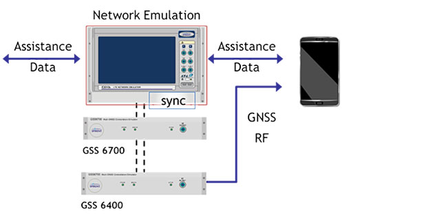
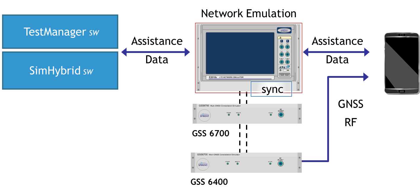
Spirent Communications today announced the availability of carrier-approved Assisted GNSS Record and Playback capabilities on its Hybrid Location Technology Solution (HLTS). This new A-GNSS Record and Playback capability provides unprecedented realism and repeatability by recording GNSS signals in the field and delivering synchronized assistance data over a radio access interface to test the A-GNSS positioning performance of mobile devices in the lab.
“With user location playing a key role in most smartphone services and applications, A-GNSS positioning performance greatly influences the end-user experience,” said Nigel Wright, vice president of wireless, Spirent Communications. “This new A-GNSS Record and Playback solution enables device manufacturers and network operators, as well as chipset and technology vendors, to accurately test this essential technology using real-world field conditions. This helps ensure high quality LBS and emergency service performance for every mobile subscriber.”
Combining GNSS signals from multiple satellite positioning systems (such as GPS and GLONASS) with assistance data delivered by the network to the device, A-GNSS is regarded as the most universal and precise positioning technology. As such, it is used in mobile devices to support the location information required by commercial services, social media and emergency services such as E911.
Although established A-GNSS simulation tools play an important role in generating repeatable and reliable controlled environments in the lab, they can have limitations when it comes to representing the full range of challenging conditions experienced by mobile users on live networks. Spirent’s A-GNSS Record and Playback addresses these limitations by capturing conditions in the field and playing them back in a reliable and repeatable lab environment. This helps to reduce device time to market and control testing cost by reducing the need for extensive field testing.
Spirent HLTS is recognized by the industry for its unique capabilities that span a wide range of test requirements from early R&D phases to mobile device acceptance. The HLTS now incorporates Spirent’s GSS6400 GNSS Record and Playback System (RPS), together with patent-pending SimHybrid software that generates and delivers the correct assistance data, synchronized with the recorded GNSS signals.
Orbit Logic announced that their SpyMeSat iPhone app is now available on the Apple App Store. The SpyMeSat app provides notifications when imaging satellites are overhead and may be taking your picture. A dynamic map shows orbit tracks and the location of satellites with upcoming passes over the user-specified location.
SpyMeSat iPhone App
According to the announcement, this is Orbit Logic’s first app targeted for consumers outside their standard customer base in the aerospace, defense, and government intelligence communities.
“This app is for everyone.” said Alex Herz, president of Orbit Logic. “Whenever I talk to people outside the aerospace industry about what I do they have so many questions. I realized there was a place for an app to provide information, education and awareness about imaging satellites to a wider audience. And it’s fun for aerospace industry insiders too!”
The SpyMeSat app uses NORAD orbit data published online by www.celestrak.com and available public information about commercial and international imaging satellites to compute and dynamically display satellite overflights and imaging pass information. The app user can drill down to see additional details about each imaging opportunity, and the app provides a page describing each satellite for those who want to learn more.
SpyMeSat users can configure the app to enable or disable individual satellites, change the location of interest, enable or disable various notification options, and specify the resolution limit for computed passes. Orbit Logic can create custom SpyMeSat solutions for any constellation of satellites. With a custom SpyMeSat solution, authorized users can make satellite tasking requests directly from the mobile device.
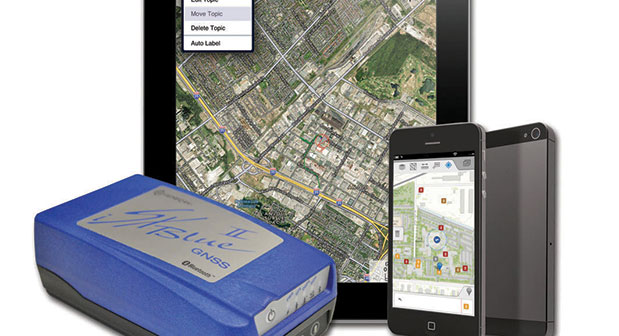
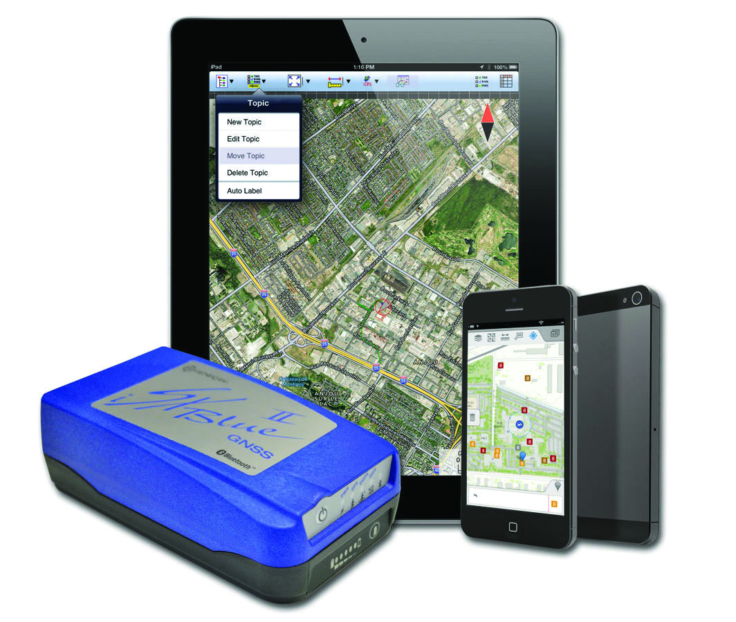
The iSXBlue II from Geneq works with the Apple iPad and iPhone.
Geneq Inc. announces the iSXBlue II GNSS, a sub-meter GNSS receiver that is Bluetooth-compatible with Apple iPads and iPhones.
Fully authorized and approved by Apple, the iSXBlue II GNSS implements an Apple proprietary Bluetooth authentication feature allowing the NMEA GNSS data to replace the internal GPS location of the iPad or iPhone. A free SDK (software development kit) is available from Geneq to further utilize all the features of the iSXBlue II GNSS.
The iSXBlue II GNSS uses both GPS and GLONASS with SBAS (WAAS/EGNOS/MSAS/GAGAN) to attain 30-cm/1-foot (RMS) accuracy in real time using free SBAS corrections. In addition to Apple iPads and iPhones, it connects wirelessly to any smartphone, handheld, tablet computer or notebook computer that is Bluetooth- compliant.
“The iSXBlue II GNSS is the first high-accuracy GNSS receiver in the world for the Apple iPad and iPhone,” said Jean-Yves Lauture, product engineer, “and by implementing both GPS and GLONASS with SBAS, it provides iPad and iPhone users real-time, sub-meter accuracy around the world.”
The iSXBlue II GNSS builds on the success of the proven SXBlue II GNSS that was designed to optimize SBAS performance under tree canopy and in rugged terrain. With the ability to track 55 satellites (31 operational GPS, 24 operational GLONASS), the SXBlue II GNSS uses between 12 and 19 satellites in view at any time, providing superior performance when working under and around tree canopy, buildings and rugged terrain.
The next-generation iSXBlue II GNSS is the same, small, palm-sized unit as the SXBlue II GNSS and utilizes a small 2.7” diameter GNSS antenna. The unit is waterproof (submersible), dustproof and ruggedized, with an IP-67 rating. Its Class 2 Bluetooth 2.0 has a typical range of 15 meters, and is Apple-approved. The internal, rechargeable, field replaceable Li-Ion battery has on-board LEDs let the user know how much battery life is left. The operating temperature range of the iSXBlue II GNSS is -40°C (-40°F) to 85°C (185°F).
In addition to the built-in long-range Bluetooth transceiver, the iSXBlue II GNSS also has a standard DE-9 RS-232 port and a USB Type B port whose outputs are fully programmable up to 10-Hz standard, and a 20-Hz option. Other optional features are L1 RTK for <2-cm real-time accuracy and base-station RTCM output.
There is no need for post-processing or other sources of differential corrections as the iSXBlue II GNSS uses WAAS (North America), EGNOS (Europe), MSAS (Japan) and GAGAN (India) satellite corrections. Users receive real-time, 30-cm/1-foot positioning all day long.
The iSXBlue II GNSS is targeted at GPS/GIS mapping professionals in industries such as forestry, utility, agriculture, environmental and other natural resource industries in addition to local, state and federal government users.
ikeGPS announced a Kickstarter fundraising effort for a smartphone laser measurement and augmented reality accessory named Spike.
According to the announcement, with Spike you can measure, map, 3D model (and share) any object up to 600 feet away by taking a snapshot on your smartphone.
The company reports that Spike’s precision enables the development of immersive laser-based smartphone apps, delivering deeply textured 3D modeling and location experiences. Its laser accuracy makes Augmented Reality (AR) experiences real. Not just because Spike enables AR apps to be incredibly precise and relevant to a user for the very first time, but also because it empowers anyone to develop and experience them on their smartphone.
The fully specified API will enable software engineers to develop immersive AR applications. By embedding specialist ikeTools into the application, or building an application over the data stream from the calibrated laser camera, Spike will give applications long range accuracy and depth perception.
According to Spike’s Kickstarter webpage, the project will be funded if $100,000 is reached by October 29, 2013. As of October 2, 2013, funding was at $74,282
Locata Fills Satellite Availability Holes in Obstructed Environments
By Chris Rizos, Nunzio Gambale, and Brendon Lilly
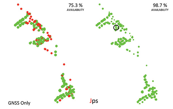
An integrated GNSS+Locata system installed on drills, shovels, and bulldozers — the full complement of high-precision machines on site — at Australia’s Newmont Boddington Gold Mine has increased positioning accuracy and availability, as well as mine operational efficiencies, demonstrating an improvement in availability over GNSS-only of 75.3 to 98.7 percent.
Many of the new paradigms in mining have at their core the requirement for reliable, continuous centimeter-level positioning accuracy to enable increased automation of mining operations. The deployment of precision systems for navigating, controlling, and monitoring machinery such as drills, bulldozers, draglines, and shovels with real-time position information increases operational efficiency, and the automation reduces the need for workers to be exposed to hazardous conditions.
GPS singly, and GNSS collectively, despite their accuracy and versatility, cannot satisfy the stringent requirements for many applications in mine surveying, and mine machine guidance and control. Increasingly, open-cut mines are getting deeper, reducing the sky-view angle necessary for GNSS to operate satisfactorily.
A new terrestrial high-accuracy positioning system can augment GNSS with additional terrestrial signals to enable centimeter-level accuracy, even when there are insufficient GNSS (GPS+GLONASS) satellite signals in view for reliable positioning and navigation. Locata relies on a network of synchronized ground-based transceivers that transmit positioning signals that can be tracked by suitably equipped user receivers.
In September 2012, Leica Geosystems launched the first commercial product integrating GNSS and Locata capabilities into a single high-accuracy and high-availability positioning device for open-cut mine machine automation applications: Leica Jigsaw Positioning System (Jps) – Powered by Locata. This article describes technical aspects of this technology and presents positioning results of actual mine operations.
In the near future — perhaps by 2020 — the number of GNSS and augmentation system satellites useful for high-accuracy positioning will increase to almost 150, with perhaps six times the number of broadcast signals on which carrier phase and pseudorange measurements can be made. However, the most severe limitation of GNSS performance will still remain: the accuracy of positioning deteriorates very rapidly when the user receiver loses direct view of the satellites. This typically occurs in deep open-cut mines as well as in skyscraper-dominated urban canyons.
Locata’s positioning technology solution provides an option either to augment GNSS with extra terrestrial signals, or to replace GNSS entirely. Locata relies on a network of synchronized ground-based transceivers (LocataLites) that transmit positioning signals that can be tracked by suitably equipped user receivers. These transceivers form a network (LocataNet) that can operate in combination with GNSS, or entirely independent of GNSS.
Pseudolites are ground-based transmitters of GPS-like signals. Most pseudolites developed to date transmit signals at the GPS frequency bands. Both pseudorange and carrier-phase measurements can be made on the pseudolite signals. The use of pseudolites can be traced back to the early stages of GPS development in the late 1970s, when they were used to validate the GPS concept before launch of the first GPS satellites.
In 1997, Locata Corporation began developing a technology to provide an alternate local GPS signal capability that would overcome many of the limitations of pseudolite-based positioning systems by using a time-synchronized transceiver. The LocataLite transmits GPS-like positioning signals but also can receive, track, and process signals from other LocataLites. A network of LocataLites forms a LocataNet, and the first-generation system transmitted signals using the same L1 frequency as GPS. Time-synchronized signals allow carrier-phase single-point positioning with centimeter-level accuracy for a mobile unit. In effect, the LocataNet is a new constellation of signals, with some unique features such as having no base station data requirement, requiring no wireless data link from reference station to mobile receiver, and no requirement for measurement double-differencing.
Improvements dating from 2005 use a proprietary signal transmission structure that operates in the license-free Industry Scientific and Medical (ISM) band (2.4–2.4835GHz), known globally as the Wi-Fi band. Within this ISM band, the LocataLite design allows for the transmission of two frequencies, each modulated with two spatially-diverse PRN codes. From the beginning the driver for the Locata technology was to develop a centimeter-level accuracy positioning system that could complement, or replace, conventional RTK-GNSS in environments such as open-cut mines, deep valleys, heavily forested areas, urban and even indoor locations, where obstruction of satellite-based signals occurs.
Leica Geosystems has been testing Locata in the Newmont Boddington Gold Mine (NBG) in Western Australia for several years. In 2006, NBG started installing Leica Geosystems high-precision GPS-based guidance systems for fleet management. The mine operators determined early on that as the pit grew deeper, they would need an alternative positioning system for these guidance systems to continue working for the life of the mine. In March 2012, Leica Geosystems deployed a world-first production version of its Jigsaw Positioning system, integrating GNSS+Locata, at the NBG mine.
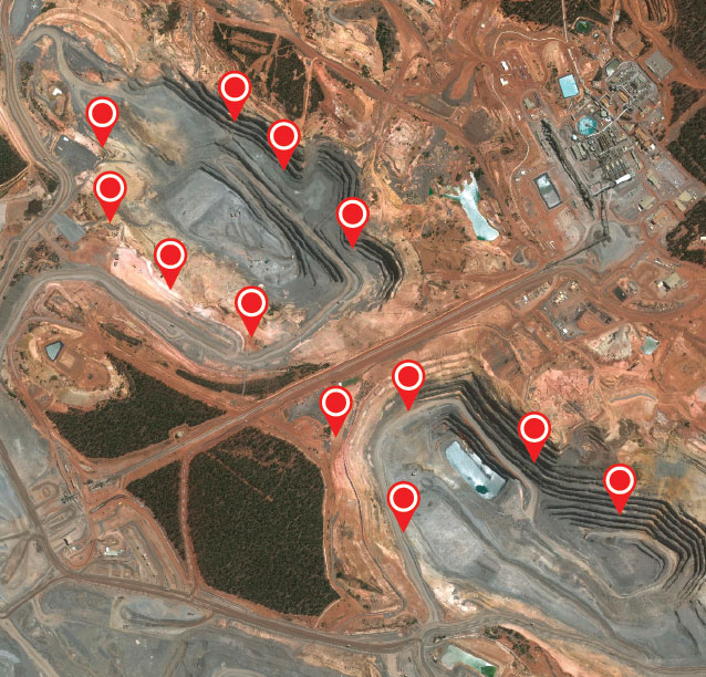
Expected to become Australia’s largest gold producer, the mine consists of two pits (Figure 1). The North Pit at NBG is currently about 1 kilometer long, 600 meters wide, and now approaching 275 meters deep.
Figure 1. Location of 12 LocataLites at NBG Mine.Figure 2. The Newmont Boddington pit, 900 feet deep and going deeper all the time, creates difficulties for GNSS equipment positioning the mine’s heavy machinery.
A single LocataNet consisting of 12 LocataLites was deployed during April and May 2012 in an initial installation designed to cover both pits in the mine. The results presented here are taken from tests in the North Pit.
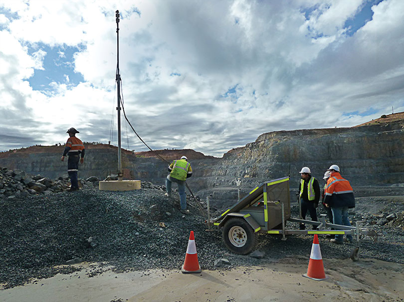
Leica’s version of the LocataLite is solar-powered and designed to be placed in the best locations to achieve the maximum benefit. As no special consideration for the location of a transmitter base station is required, the LocataLites can be placed in areas on the rim of the pit or just above the machines operating in the pit floor. The only set-up requirement is that they are able to see at least one other LocataLite to synchronize their transmissions to around 1 nanosecond or better throughout the mine.
Each Jps transmit tower has four small patch antennas mounted in an array. The uppermost is a GNSS antenna used to self-survey the top of the tower, and hence derive the positions of the other antennas below it on the tower. The Locata transmit 1 antenna is mounted directly under the GNSS antenna. The Locata receive antenna is directly under that, and the Locata transmit 2 antenna is around two meters lower down on the tower.
All the antennas are separated by a known distance, and the LocataLite transmit antennas can be tilted down into the pit to maximize the signal broadcast into the area. Each LocataLite transmits four independent positioning signals, two signals from each transmit antenna. These signals provide a level of redundancy and greatly assist in the mitigation of multipath problems in the pit, thereby contributing to the robustness and reliability of the positioning solution.
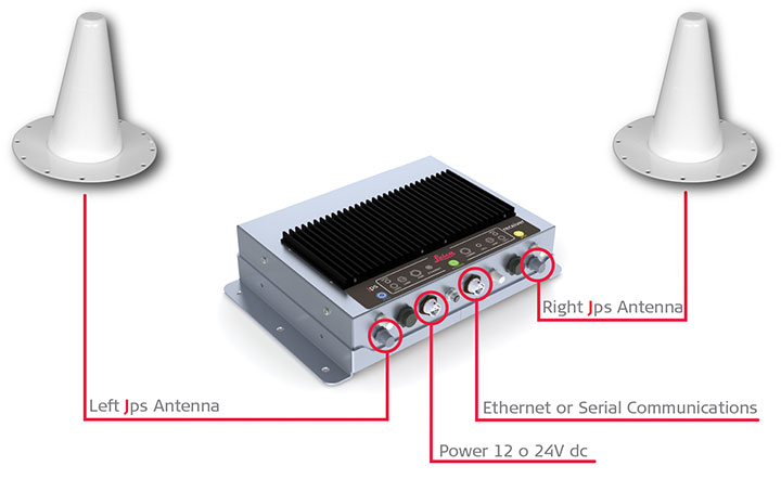
Jps receivers were first installed on two production drill rigs in April 2012. Installation on drills was the highest priority because they are the machines at NBG that operate closest to pit walls and other obstructions, and therefore stood to benefit most from having more reliable positioning. Each Jps receiver incorporates two GNSS and two Locata receivers (Figure 3). One GNSS and Locata receiver pair is connected to a co-located antenna on one side of the machine and the other GNSS and Locata receiver pair is connected to the other co-located antenna. The GNSS receivers obtain their RTK corrections from an RTK base station. The Locata receivers do not require any corrections. The system uses the NMEA outputs from both pairs of receivers to determine the position and heading of the drill rig for navigation purposes.
Figure 3. Jps receiver with integrated GNSS and Locata receivers and two receiver antennas.
The goal of the Jps receiver is to improve the availability of high-accuracy RTK positions with fixed carrier phase integer ambiguities. The results presented here are therefore divided into three sections:
Improvements in availability over a two-month period for all the data in the North Pit.
Improvements in availability for an area in the pit where the GNSS savings are expressed in dollar terms.
Accuracy results achieved and maintained in this GNSS-degraded area.
The performance results shown here are real-world samples of the system operating on drills at NBG. However, it will be appreciated that GNSS satellites are in constant motion, so GNSS-only position availability in different parts of the pit changes by the hour. The results therefore only apply to those drills in those positions in the pit at that time.
Another drill a little distance away in the same pit could experience far better or far worse GNSS availability at exactly the same time.
Overall Availability
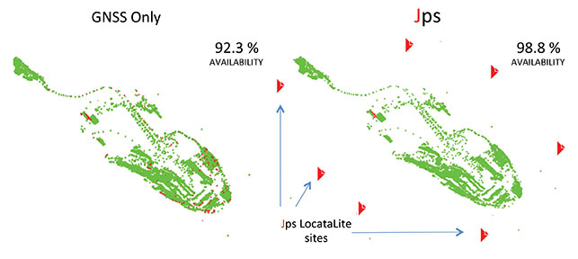
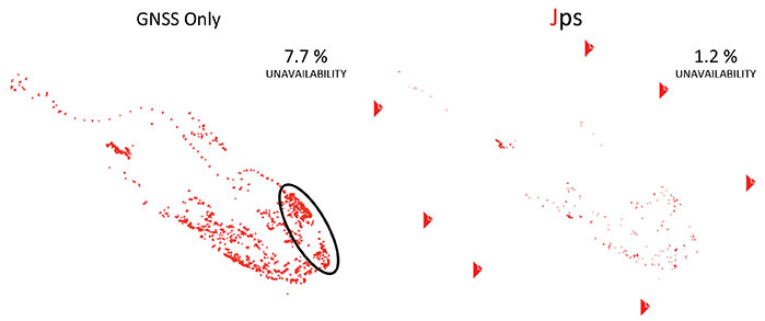
Figure 4 shows the performance difference between using GNSS-only (left) and Jps GNSS+Locata (right). The data for these plots was recorded for the two drills that contained the Jps receiver in the North Pit during the months of April and May 2012. A green dot represents the time the receiver had a RTK fixed solution, and a red dot represents all other lower-quality position solutions — essentially when the receiver was unable to achieve the required RTK accuracy because of insufficient GNSS signals or geometry.
Figure 4. Plots of availability and position quality in the North Pit at NBG for April and May 2012 for GNSS (left) and Jps (right). Green = RTK (fixed) solution, Red = all lesser quality solutions.
Although the availability of GNSS-only RTK fixed position solutions was reasonably good over this entire area, being at the 92.3 percent level at that time, the Jps nevertheless provided a measurable improvement of 6.5 percent to availability, bringing it up to 98.8 percent. Considering that during those two months, the two drills spent a total of 72.24 operational days in the North Pit, this improvement equates to nearly 4.7 days or 112.7 hours of additional guidance availability.
Figure 5 highlights the low positional quality for the GNSS-only solutions and how Jps significantly improved the availability in areas of limited GNSS satellite visibility.
Figure 5. Plots showing non-RTK quality positions, demonstrating that Jps can help reduce lesser-quality RTK solutions. (Performance in the circled area is highlighted in more detail in Figure 6.)
Availability in Poor GNSS Visibility
The ellipse in Figure 5 highlights a particular location in the North Pit where GNSS positioning consistently struggles due to the presence of the northern wall and to a lesser extent from the eastern wall. The integration of GNSS and Locata signals improved availability as shown in Figure 6, which in this case increased by 23.4 percent.
Figure 6. Zoomed-in area where GNSS performance was poor between May 2 and May 4, 2012. The circled area shows where the accuracy tests were performed.
As the machine downtime due to not having a RTK position costs the mine approximately U.S. $1000 per hour for each drill, the improvement in availability of 112.7 hours for just the two drills shown in Figure 5 over the two months equates to a savings of $112,700 in operational costs. This productivity increase is significant, considering that the GNSS-only availability in this case still seems relatively good at 92.3 percent. If the GNSS availability for those two months was more like 75 percent — as was the case shown in Figure 6 for the two days in May — then the cost savings become far greater, approaching nearly $400,000, for just two drills over two months. Even a small increase in productivity brings a significant financial benefit ($110,000 per hour) when all 11 drill rigs running in the mine are affected by loss of GNSS positioining availability, yet continue to operate with Jps.
Today all 11 drills in the pits have been fitted with the Jps GNSS+Locata Receivers. As a point of reference to emphasize the level of operational savings: if the Jps had been fitted to all 11 drills during the April and May 2012 period shown in the above results, the cost savings at that time would have been on the order of $1,000,000. It is clear that the savings in production costs that can be gained from improving the availability to the fleet guidance system has a significant impact on the return-on-investment, potentially covering the installation costs within months of deployment. It should also be emphasized that as the pits get deeper, GNSS availability will only degrade further, and the evident production and dollar benefits of the integrated GNSS+Locata system become even larger.
Relative Accuracy
The above levels of improvement in availability are of no benefit if the position accuracy is not maintained within acceptable limits. In order to compare the relative accuracy between the two systems, a dataset was taken from the same data above (circle in Figure 6) when the machine was stationary.
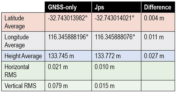
The average position difference between the GNSS-only and Jps receivers for the hour-long dataset was 1.2 centimeters horizontally and 2.7 cm in the vertical component (Table 1). The spread of the position solutions for the two receivers were comparable in the horizontal, with Jps providing a slightly better horizontal RMS value due to the extra Locata signals being tracked and the stronger overall geometry. Additionally, Jps showed a better RMS in the vertical compared to GNSS-only.
Table 1. Comparison of relative accuracy and RMS between the GNSS-only and GNSS+Locata solutions.
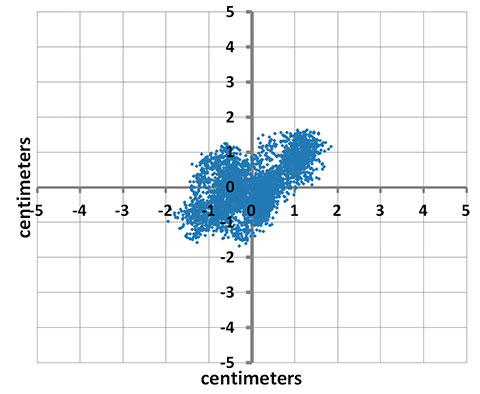
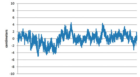
Figure 7a shows the spread of horizontal positions for the Jps receiver, where 0,0 is the mean horizontal position during this time. Note that all the positions are grouped within +/-2 cm of the mean without any outliers. Figure 7b shows the corresponding spread in the vertical positions. These are well within the acceptable accuracy limits required by the machine guidance systems used at the mine.
Figure 7A. Scatter plot of the positions from the Jps receiver over a period of over an hour.Figure 7B. Vertical error for same sample set as Figure 7a.
Concluding Remarks
Based on the experiences at Newmont Boddington Gold, use of Jps has improved the operational availability of open-pit drilling machines by at least 6.5 percent by reducing the outages in 3D positioning caused by poor GNSS satellite visibility commonly associated with deep pits. When Jps is subjected to much harsher conditions closer to high walls, the Jps continues to perform and the improvement in availability compared to GNSS-only is more significant while still maintaining RTK-GNSS levels of accuracy. The additional availability achieved translates directly into cost savings in production for the mine.
Acknowledgments
The first author acknowledges the support on the Australian Research Council grants that have supported research into pseudolites and Locata:
LP0347427 “An Augmented-GPS Software Receiver for Indoor/Outdoor Positioning,”
LP0560910 “Network Design & Management of a Pseudolite and GPS Based Ubiquitous Positioning System,”
LP0668907 “Structural Deformation Monitoring Integrating a New Wireless Positioning Technology with GPS,”
DP0773929 “A Combined Inertial, Satellite & Terrestrial Signal Navigation Device for High Accuracy Positioning & Orientation of Underground Imaging Systems.”
The authors also thank the many people that have contributed to the development of the Leica Jps product. The Leica Geosystems Machine Control Core and CAL teams in Brisbane and Switzerland, other Hexagon companies such as Antcom Corporation and NovAtel, the Locata team in Canberra and the United States, and the people at Newmont Boddington Gold that have gone out of their way to make this a success.
Chris Rizos is a professor of geodesy and navigation at the University of New South Wales; president of the International Association of Geodesy; a member of the Executive and Governing Board of the International GNSS Service (IGS), and co-chair of the Multi-GNSS Asia Steering Committee.
Nunzio Gambale is co-founder and CEO of Locata Corporation, and represents the team of engineers who invented and developed Locata.
Brendon Lilly is the product manager for the Leica Jps product at Leica Geosystems Mining and has worked for more than 20 years in both software and hardware product development. He has a Ph.D. from Griffith University.
Thousands of high-speed pursuits by law enforcement take place in the U.S. every year, which can endanger other vehicles and property. A new product aimed at law enforcement is designed to help police track cars during these high-speed chases.
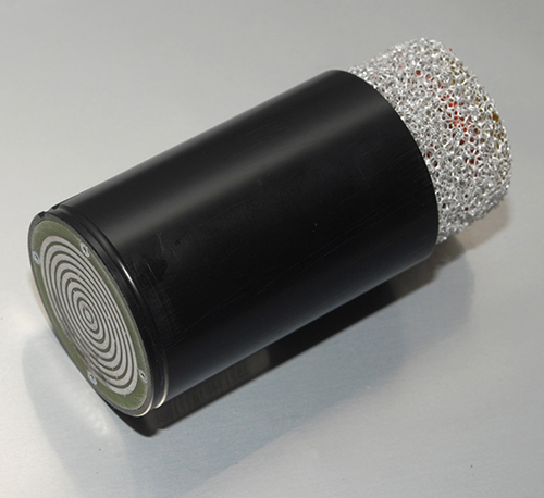
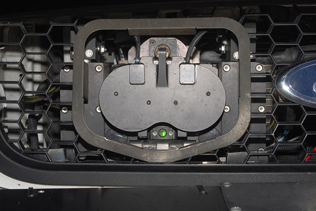
The StarChase system pursuit reduction technology contains a miniature GPS module encased in a tracking projectile/tag and a launcher mounted on a police vehicle. During a pursuit, a GPS tracker tag is shot with compressed air out of a patrol car’s hood onto the car being pursued, to identify the vehicle.
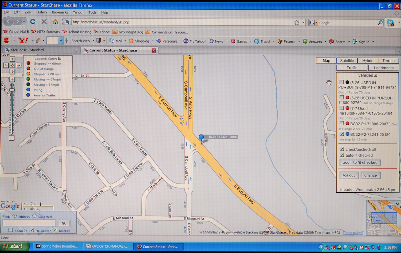
The compressed-air launcher, mounted behind the grille of a police cruiser, uses a laser to target the fleeing vehicle. It discharges a projectile/tag containing the GPS module. The projectile adheres to the suspect vehicle and transmits coordinates back to dispatch. The dispatcher then views the location and movements of the tagged vehicle in near real-time on a digital road map via a secure Internet connection.
Through the efficient use of technology, a high-speed chase has been replaced with a safer interdiction strategy, according to the company.
The StarChase mapping platform is a secure, scalable Web-based solution that does not require special hardware to operate. It is compatible with existing CAD and AVL systems.
The StarChase compressed air launcher under the hood.The StarChase projectile.Tagged vehicles are tracked by dispatch.
Linx Technologies has launched its GM Series GNSS receiver module. The module is an autonomous, high-performance GNSS receiver designed for navigation, asset tracking and positioning applications of all kinds. Based on the MediaTek chipset, it can simultaneously acquire and track several satellite constellations. These include GPS, Europe’s Galileo, Russia’s GLONASS, and Japan’s QZSS.
The GNSS receiver module provides exceptional sensitivity, even in dense foliage or urban canyons, Linx Technologies said. Hybrid ephemeris prediction can be used to achieve cold start times of less than 15 seconds. By combining this feature with the module’s very low power consumption, battery life is maximized in battery-powered systems.
With an output of standard NMEA data, the GM Series GNSS receiver is self-contained and only requires an antenna. It powers up and outputs position data without any software set-up or configuration, making the GM Series easy to integrate, even by engineers without previous RF or GNSS experience. However, if technical support is needed, our knowledgeable team of engineers can provide guidance.
The GM Series module operates at a low 16mA tracking supply current. This is less than half the supply current of competitive modules.
In addition, the available GPS Master Development System connects a GM Series Evaluation Module to a prototyping board with a color display that shows coordinates, speedometer and compass for mobile evaluation. A USB interface allows simple viewing of satellite data and Internet mapping, as well as custom software application development.