The Navigation Sensor Switching in Hostile Environments (NAV-SSHE) project aims to design, prototype and demonstrate new solutions for positioning, navigation and timing using 5G plus GNSS for critical applications in hostile environments. NAV-SSHE is supported by the European Space Agency (ESA).
Geolocation company M3 Systems Belgium is taking part in the project in collaboration with Telespazio Belgium. The project began in September 2021 and will last until January 2023.
In the context of NAV-SSHE, M3 Systems Belgium will implement both a GNSS and a 5G signal based on positioning engines. The output of both engines will be fused to provide a unique solution with increased robustness.
The complete system will be demonstrated on two real-use cases:
autonomous vehicles on an airport platform (specifically autonomous lawn mowers)
autonomous docking of vessels in port
The demonstrations will also be used to test potential use of these technologies for drone applications — specifically for the navigation system of the autonomous remotely piloted aircraft Boreal.
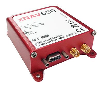
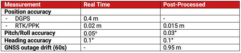
In 2021, OxTS released its smallest, lightest and most affordable inertial navigation system (INS) to date — the xNAV650.
At release, the xNAV650 detailed real-time specifications only. However, after additional testing, OxTS has announced post-processed specifications.
Because of its small size and low weight, the xNAV650 is suitable for SWaP-constrained applications. It is also used in many mobile-mapping scenarios. Alongside OxTS Georeferencer, measurements created by the xNAV650 can be used to georeference point clouds from multiple lidar sensors.
By announcing these new specifications, OxTS aims to keep surveyors informed of the performance they can expect from the xNAV650 in both real time and post-processing.
OxTS has been manufacturing INS for more than 20 years. Their INS are widely used in both the automotive testing and survey and mapping industries.
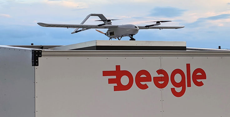
Hamburg-based start-up Beagle Systems has begun building a nationwide network of landing and charging stations for drones.
In Hanstedt (Lüneburger Heide) in the Lower Saxony region of Germany, the first hangar has been set up with an unmanned aerial system (UAS). From there, every surrounding place in Lower Saxony can be reached in a short time.
The drone will be deployed from the Beagle Systems headquarters in Hamburg. Beagle Systems has the corresponding permits for flights beyond visual line of sight (BVLOS).
“The start in Hanstedt is an important step for us,” said Oliver Lichtenstein, one of the three founders of Beagle Systems. “From here we can reach an area of 780,000 hectares in Lower Saxony. As the first provider of drone flights, we are thus on call within a short time at the customer’s site.”
The drone flight can be controlled entirely from Hamburg; on-site personnel deployment is not necessary. This eliminates personnel costs as well as time spent traveling to and from the site. Because of this, Beagle Systems can carry out drone flights at a much lower cost than other providers.
“Our goal is to build a nationwide network of charging stations within the next few years,” said Mitja Wittersheim, COO of Beagle Systems. “An EU-wide expansion is then the next step.” The expansion of the network would allow drone specialists to access a ready-to-go drone from Hamburg for customers at any location within the European Union.
Beagle Systems is a drone-as-a-service provider specializing in long-range flights with unmanned aerial systems. The drones are already in use for the inspection and monitoring of large infrastructure facilities such as power grids.
The company also plans to tap into the multi-billion dollar market of delivery, courier and express services. The Beagle M drone used in Hanstedt was developed in-house. It has a wingspan of 2.50 meters and can transport a load of up to three kilograms.
How inertial systems and GNSS availability will help
By Kana Nagai, Matthew Spenko, Ron Henderson and Boris Pervan
Self-driving cars in urban environments can be problematic. The required multi-sensor automated systems will include GNSS, but buildings block and reflect GNSS signals, reducing system availability and accuracy. Researchers from the Illinois Institute of Technology report on how inertial navigation systems coupled with wheel-speed sensors and vehicle dynamic constraints can help.
Innovation Insights with Richard Langley
ARE WE THERE YET? This was a familiar refrain from the backseats of parents’ cars when traveling to a holiday destination or to grandparents when I was growing up. We didn’t have videos on a display attached to the seats in front of us or (who could imagine?) our own personal communication device on which we could call up games, movies or social media channels.
But I’m not talking about that complaint from our childhoods. I’m asking if we have arrived at the era of the self-driving car. The answer is yes and no. It all depends on what you mean by “self-driving.” We reviewed some of the technologies needed for self-driving or autonomous vehicles in this column in June 2019. And we indicated in the introduction to that column that vehicle autonomy has several levels. SAE International, formerly known as the Society of Automotive Engineers, has defined six levels of autonomy that can be briefly described as Level 0 – no automation; Level 1 – hands on/shared control; Level 2 – hands off; Level 3 – eyes off; Level 4 – mind off; and Level 5 – steering wheel optional.
Already, Level 1 automation is widely available in modern cars with adaptive cruise control, parking assistance, lane-keeping assistance and automatic emergency braking among the features being offered.
Level 2 automation, where the automated system takes full control of the vehicle’s acceleration, braking and steering, is available in some production models, although the “hands-off” designation is not to be taken literally — most motor vehicle laws require drivers to keep their hands on the steering wheel.
Between Level 2 and Level 3, we have conditional automation — the car can drive itself, but the driver must stay alert and be prepared to take over immediately.
Level 3 is high automation, where a computer fully drives the car at certain times on certain routes such as a highway; while the driver can perform other tasks such as reading a book, they must be prepared to take over operation of the vehicle within a few seconds if alerted by the automated system. While test campaigns are still ongoing, some jurisdictions permit Level 3 operation by ordinary drivers on some roads, and customers will soon be able to buy vehicles with this level of automation. Widespread use of
Level 4 and Level 5 automation is further off (some would say quite a way off) and remains in development. But famously, last year, Toyota operated Level 4 self-driving shuttle vehicles around the Tokyo 2020 Olympic Village.
A lot more work needs to be done before we will have arrived at the era of the fully self-driving car that will be able to travel on any road, anywhere in the world, all year around, in all weather conditions. In particular, self-driving cars in urban environments (as opposed to highway driving) can be problematic.
The required multi-sensor automated systems will include GNSS, but buildings block and reflect GNSS signals, reducing system availability and accuracy. In “Innovation” this month, researchers from the Illinois Institute of Technology report on how inertial navigation systems coupled with wheel-speed sensors and vehicle dynamic constraints can help.
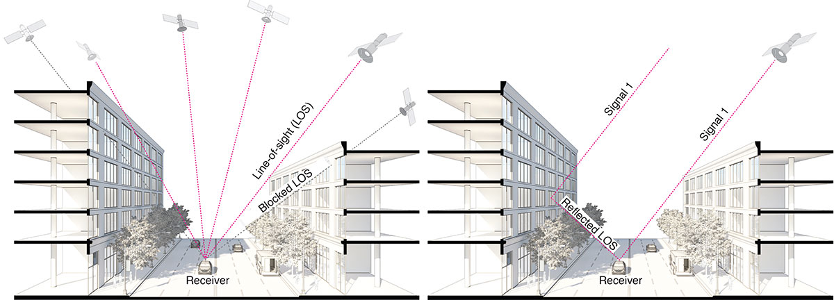
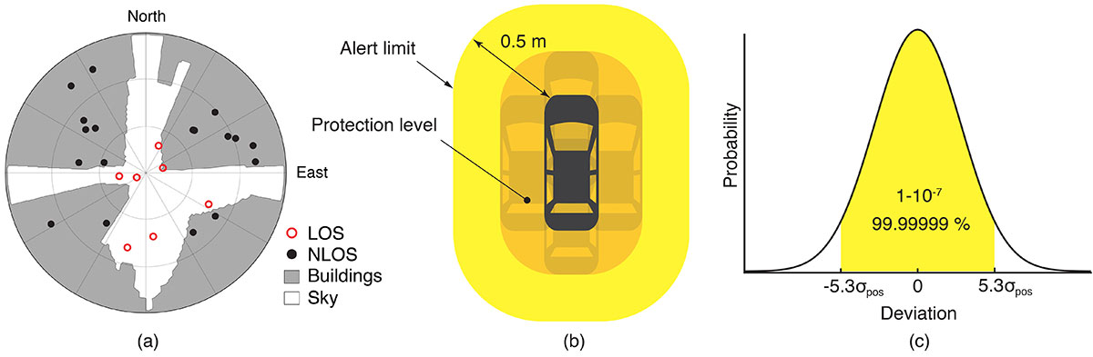
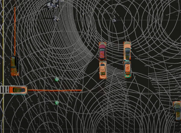
GNSS provides navigation services globally, but satellite visibility in urban areas is limited by high-rise buildings. This creates a mixture of GNSS available and denied environments (see FIGURE 1) — users do not generally know where the system can maintain sufficient levels of accuracy and integrity for a particular application. To begin to address the issue for self-driving cars, we evaluated GNSS-only availability in downtown Chicago.
FIGURE 1. The figure depicts three types of potential GNSS signal reception: direct LOS signals and blocked LOS signals (left) and reflected LOS signals (right). (Image: Authors)
GNSS signal prediction in urban environments has been conducted in previous work. For example, the concept of “shadow matching” was developed to identify GNSS signal blockages in urban canyons. Overlaying sky plots on a hemispherical sky view can be used to distinguish between line-of-sight (LOS) and non-line-of-sight (NLOS) signals (see FIGURE 2a). Reflected rays can be predicted using Householder transformations to reveal potential multipath conditions. Satellites producing blocked or reflected (NLOS) signals should be excluded to maintain integrity.
FIGURE 2. (a) A hemispherical sky view in an urban environment. (b) Illustration of a protection level and an alert limit. To ensure integrity, the protection level must not exceed an alert limit. (c) The allowable probability of exceedance is assumed to be 10−7 in this work. (Image: Authors)
When the number of visible satellites is greater than three, GNSS can resolve vehicle position. However, even in cases where enough satellites are visible, the satellite geometries are generally weak because the dilution of precision (DOP) is adversely affected by the buildings partially blocking the sky. Horizontal positioning error must be bounded by a protection level computed by the vehicle. Then, for navigation to be deemed available, the protection level must not exceed a required alert limit (see FIGURE 2b). The maximum allowed probability of exceedance (see FIGURE 2c) and the alert limit can together be used to determine the maximum allowable position error standard deviation.
Even if the protection level is far below the alert limit in an open-sky environment, it will frequently exceed the alert limit once the vehicle enters a city. GNSS alone is generally not able to maintain availability, so integration with other sensors is needed. Tightly coupling inertial navigation systems (INS) with GNSS using the extended Kalman filter (EKF) provides better estimation in urban environments. The EKF algorithm also enables integration of wheel-speed sensors and vehicle dynamic constraints. These integrated navigation systems will improve availability, but it is still unclear how long such a system can be expected to maintain fault-free integrity in a congested city.
Focusing on the problem of self-driving cars in urban environments, we evaluate protection levels of navigation with practical integrated sensors: GNSS, INS, a wheel-speed sensor (WSS) and vehicle dynamic constraints (VDC). The goal is to develop the means by which we can determine locations where external ranging sources (such as lidar) are needed to maintain continuous navigation with fault-free integrity.
GNSS-ONLY AVAILABILITY
For GNSS availability evaluation, we assume an integrity requirement that the probability of exceeding a 0.5-meter alert limit must be lower than 10−7. The 0.5-meter alert limit therefore corresponds to approximately five times the position standard deviation, so the maximum allowable position error standard deviation is then approximately 0.1 meters. Accuracy at this level clearly requires differential GNSS carrier-phase measurements. We assume a nominal GNSS double difference (DD) carrier ranging error standard deviation of approximately 0.02 meters, and that carrier cycle ambiguities can be readily resolved in an open-sky environment prior to initiation of vehicle motion.
Given the assumptions made of the maximum allowable position error standard deviation and the GNSS ranging error standard deviation, the maximum allowable horizontal dilution of precision (HDOP) is about 5.
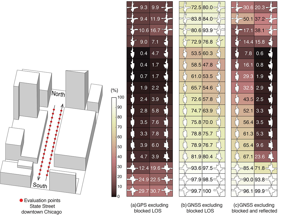
FIGURE 3 shows GPS and GNSS availability — the fraction of time the HDOP requirement is met over 24 hours — along a section of State Street in downtown Chicago. The availability results using GPS only and excluding only blocked LOS signals ranged from 0% to 9% along the block and 9% to 30% at the intersections (see FIGURE 3a). Using four full GNSS constellations (GPS, Galileo, GLONASS and BeiDou), availability ranged from 48% to 82% along the block and 72% to 100% at the intersections (see FIGURE 3b).
FIGURE 3. The percentage of GPS or GNSS availability in 3D-mapped downtown Chicago. We exclude satellites producing blocked LOS signals or both blocked and reflected LOS (NLOS) signals from the measurements. Each column expresses a lane of southbound or northbound travel. The availability is the percentage of total time when HDOP meets the self-driving car integrity requirements in 24 hours. (Image: Authors)
When we also excluded satellites producing reflected LOS signals that reach the vehicle, the availability dropped significantly at every point (see FIGURE 3c). We assert that FIGURE 3c expresses the reality of GNSS availability because building-reflected multipath signals degrade positioning accuracy and would affect integrity negatively. It’s obvious from these results that GNSS alone is insufficient to meet the autonomous driving requirements in an urban environment, and multi-sensor integrated navigation systems are needed to augment poor GNSS signal availability.
MULTI-SENSOR INTEGRATION
We begin by considering tightly coupled INS/GNSS integration using an EKF, and then integrate a realistic sensor suite including WSS and vehicle dynamic constraints that enforce resistance to lateral sliding and vertical movement. If it is known from another source that the vehicle is not moving (for example, it is in the parking gear), a static mode constraint (SMC) can also be applied.
INS/GNSS Integration. Tightly coupled INS/GNSS integration with an EKF uses the INS measurement to predict vehicle motion. The continuous process model uses a state vector having the position in the navigation frame, the velocity, the attitude, bias errors and cycle ambiguities, with the input vector having accelerometer-specific force measurement in the body frame and gyro-rotation-rate measurements. A white-noise vector drives the inertial measurement unit (IMU) states.
The GPS/GNSS measurement model includes the measurement vector having carrier and code phases, and the observation matrix containing LOS vectors and the vector of white receiver thermal noise.
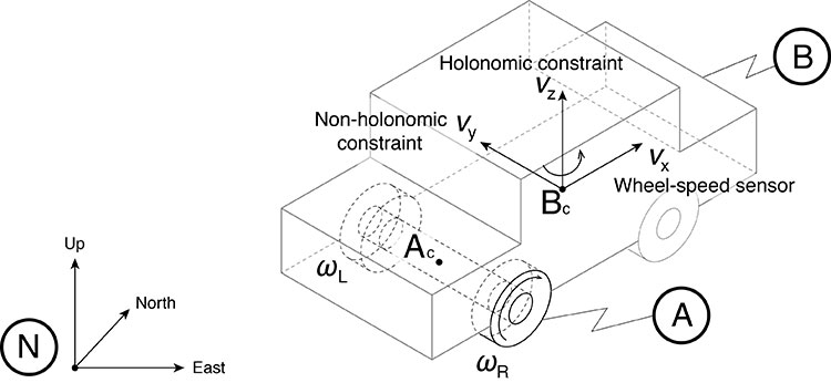
INS/GNSS/WSS/VDC Integration. For the vehicle in motion, we developed a model consisting of a WSS measurement in the along-track direction, a non-holonomic constraint resisting lateral sliding, and a holonomic constraint on vertical movement (see FIGURE 4).
The INS/GNSS/WSS/VDC integration using the EKF consists of the process model and the measurement models.
FIGURE 4. The measurement model consisting of the WSS measurement in the along-track direction (vx), non-holonomic constraint resisting lateral sliding (vy), and holonomic constraint on vertical movement (vz). N is the navigation frame, Ac is the rear-axle center point and Bc is the center point of the body-fixed frame. (Image: Authors)
INS/GNSS/SMC Integration. The static mode constraint provides zero-velocity measurements to the EKF measurement update to mitigate position error propagation. We use SMC only when it is known that the vehicle is not moving; for example, when the vehicle is in the parking gear.
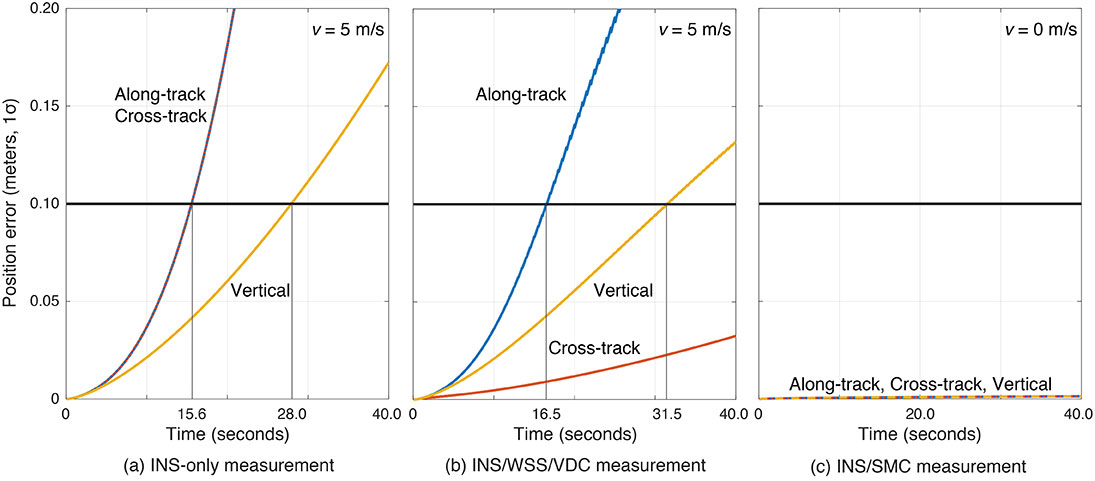
Error Propagation Analysis. We tested the time from perfect initialization to when position error exceeds 0.1 meters in GNSS-denied environments. FIGURE 5 shows the error growth in the along-track (x), the cross-track (y) and the vertical (z). The error specifications for a STIM300 tactical-grade IMU are used in this analysis. The standard deviation of the WSS measurement noise is assumed to be 0.05 meters per second, and the standard deviation of the movement constraint violations is 0.001 meters per second. The vehicle is moving at 5 meters per second except when we test the SMC.
The INS can coast 15.6 seconds before the position error standard deviation exceeds 0.1 meters in both the along-track and the cross-track directions (see FIGURE 5a). The INS/WSS/VDC can coast 16.5 seconds in the along-track direction, and significantly more than 40 seconds (the simulation duration) in the cross-track direction (see FIGURE 5b). In static mode, INS/SMC estimate errors do not grow with time in any direction, as expected (see FIGURE 5c). In GNSS-denied environments, the non-holonomic constraint suppresses the cross-track position error, but the WSS measurement hardly affects the along-track position error. The SMC works perfectly, but the usage is limited to when the vehicle is known to be stationary.
FIGURE 5. The vehicle position error growth vs. time in the along-track (x), cross-track (y) and vertical (z) directions. Each graph represents the navigation system introduced in the multi-sensor integration section. The vehicle is moving at 5 meters per second (a and b) or 0 meters per second (c). (Image: Authors)
SIMULATION SCENARIO
We imagine a future driverless-car mission scenario in which multi-sensor navigation systems are practicable. To minimize congestion in a city, autonomous vehicles will be held outside the urban core when not in use. In the clear open-sky environment, a vehicle in a parking lot completes GNSS initialization using the INS/GNSS/SMC system. Once requested for action, the vehicle departs for the city from the parking lot, and the motion of the vehicle improves alignment by the INS/GNSS system. Safe navigation can be ensured using the system to provide continuity under overpasses and bridges in the open-sky environment. Upon entering the urban core, navigation becomes more dependent on the INS/WSS/VDC system.
A reasonable numerical target for differential GNSS initialized position error is 0.02 meters, and for the INS alignment yaw angle error 0.1 degrees.
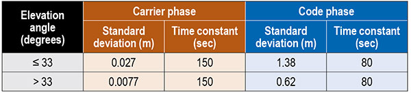
Local GNSS multipath errors from nearby vehicles will vary with the satellite elevation angle. Prior experimental results show that lower elevation-angle satellite signals (below 33 degrees) are much more likely to be impacted by multipath than higher ones (see TABLE 1).
Table 1. The nominal GNSS multipath error values in the simulation.
INITIALIZATION AND ALIGNMENT
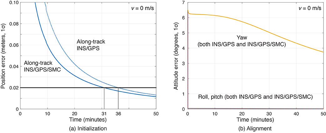
Initialization takes place in a parking lot with a clear sky view. A vehicle is in the parking gear, enabling SMC to be applied. FIGURE 6a shows a typical example: with INS/GPS/SMC, system initialization takes about 31 minutes, and with INS/GPS, about 36 minutes. Therefore, SMC does speed up GPS initialization, although the improvement is modest.
The yaw angle is not aligned during the initialization, but roll and pitch are immediately aligned (see FIGURE 6b). Earth’s gravity affects roll and pitch angle alignment but not yaw angle.
Yaw angle alignment cannot be performed when the vehicle is stationary or moving with constant velocity. Accelerated motion, either straight or turning, is required.
FIGURE 6. (a) Comparisons of initialization time between INS/GPS and INS/GPS/SMC in an open-sky environment. The INS/GPS/SMC system initializes rapidly. (b) Transitions of roll, pitch, yaw alignment during the initialization. Yaw angle alignment cannot be performed when the vehicle is stationary. (Image: Authors)
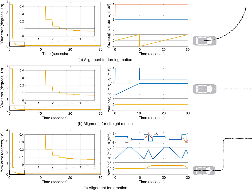
FIGURE 7 shows the behavior of the yaw angle error standard deviation using the INS/GPS system when centripetal (see FIGURE 7a) or tangential (see FIGURE 7b) acceleration is applied. The yaw angle can be aligned in a couple of seconds for either type of acceleration. To represent typical initial motions of self-driving cars, we model a parking-lot departure via a “Z”-shaped path. In this scenario, the yaw alignment error reaches 0.1 degrees within a couple of seconds (see FIGURE 7c).
FIGURE 7. The behavior of yaw angle error when centripetal (a) or tangential (b) acceleration is applied; (c) shows the behavior while following a z-shaped path. The yaw angle can be aligned in a couple of seconds in each case. (Image: Authors)
EVALUATION IN URBAN ENVIRONMENTS
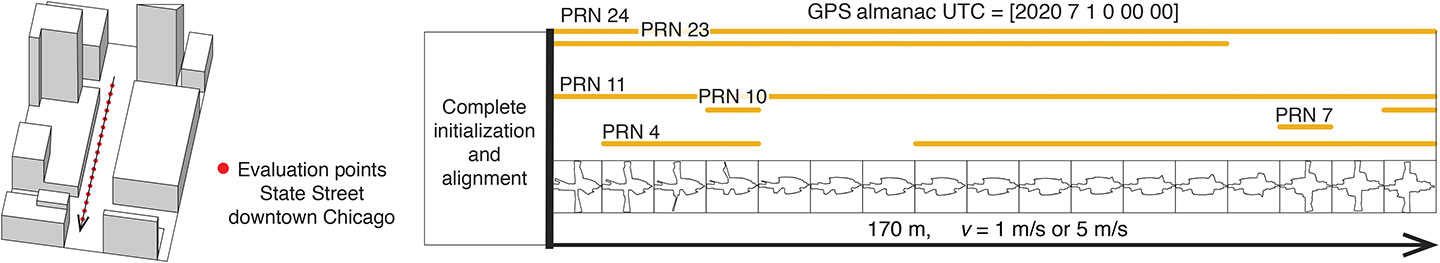
After initialization and alignment in the open-sky environment, we simulated the vehicle traveling into the urban core. The urban environment in our study is 3D-mapped State Street in Chicago, which runs north-south and transits from low-rise neighborhoods to central downtown. We selected one congested section surrounded by tall buildings and computed the position error standard deviation along the path. The evaluation points are at 10-meter intervals over a total distance of 170 meters. The yellow lines in FIGURE 8 denote the visible satellites, identified by their pseudorandom noise (PRN) code numbers, at each point. We assume for convenience that the INS/GPS system is initialized and aligned at the first evaluation point. In reality, we would expect a degraded initial condition because we are starting the simulation in an urban canyon.
FIGURE 8. Evaluation points and PRN numbers of visible satellites at each point. (Image: Authors)
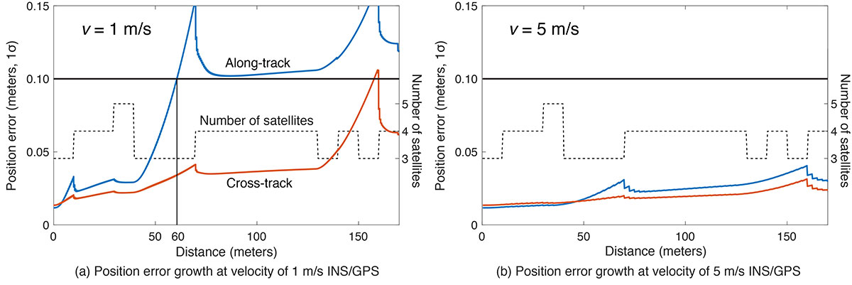
In the first simulation, the car equipped with the INS/GPS system moved either 1 or 5 meters per second. The y-axis in FIGURE 9 represents the position error standard deviation, and the x-axis represents the distance in meters. The dotted line expresses the number of visible satellites. The error when the vehicle velocity is 1 meter per second exceeded the maximum allowable position error standard deviation of 0.1 meter, at the distance of 60 meters. However, when the velocity was 5 meters per second, the maximum allowable position error standard deviation was never reached. It is also clear from the figures that error propagation is significantly affected by the number of visible satellites.
FIGURE 9. A comparison of position error growth between velocities of 1 meter per second and 5 meters per second. (Image: Authors)
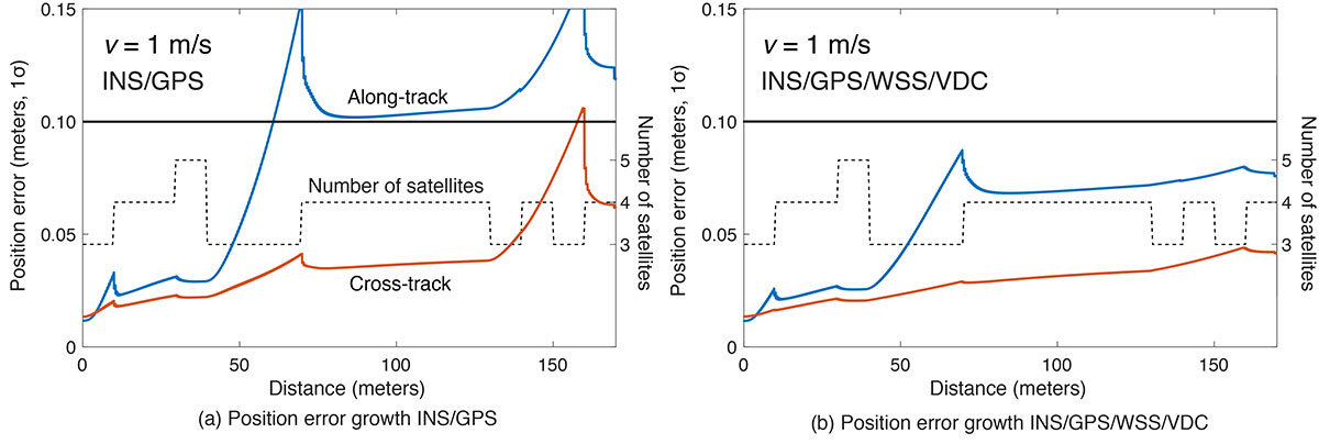
In the second simulation, we compared two different navigation systems, INS/GPS and INS/GPS/WSS/VDC. The vehicle moved at 1 meter per second in the same urban environment. The INS/GPS/WSS/VDC system does provide relief, but the error propagation is still clearly affected by the number of visible satellites (see FIGURE 10).
FIGURE 10. A comparison of position error growth between the INS/GPS and INS/GPS/WSS/VDC systems for a velocity of 1 meter per second. (Image: Authors)
In GNSS-challenged environments, INS error propagation is a function of time. When a vehicle moves faster, it clears the blockage area more quickly, reducing the impact of INS drift — a function of time, not distance. In contrast, GNSS error is completely determined by location. Because INS error propagation depends on how long the vehicle stays in an area of GNSS outage, protection levels for trips through the same area will be different if the vehicle is smoothly cruising or gets stuck in a traffic jam.
CONCLUSION
To gain a better understanding of how long and under what local conditions multi-sensor integrated navigation systems can maintain fault-free integrity, we evaluated navigation positioning errors in 3D-mapped downtown Chicago. The system we developed consists of sensors with which self-driving cars would reasonably be equipped: GNSS, INS, WSS and dynamic constraints. We showed that INS/GPS position errors along the path depend very strongly on the vehicle’s speed. When the system is augmented with WSS/VDC, position errors are suppressed, but the error propagation is still strongly influenced by the number of visible satellites.
ACKNOWLEDGMENTS
The research described in this article is supported by the National Science Foundation. Figure 1 was created by Alexis Arias of the Landscape Architecture + Urbanism Program at the Illinois Institute of Technology (IIT). The authors greatly appreciate the advice and help of Nilay Mistry from that program.
This article is based on the paper “Evaluating INS/GNSS Availability for Self-Driving Cars in Urban Environments” presented at ION ITM 2021, the virtual 2021 International Technical Meeting of The Institute of Navigation, Jan. 25–28, 2021.
KANA NAGAI is a Ph.D. candidate and research assistant in mechanical and aerospace engineering at IIT.
MATTHEW SPENKO is a professor of mechanical and aerospace engineering at IIT. He earned his M.S. and Ph.D. degrees in mechanical engineering from the Massachusetts Institute of Technology.
RON HENDERSON is a professor and director of the Landscape Architecture + Urbanism Program at IIT. He earned his Master of Landscape Architecture and Master of Architecture from the University of Pennsylvania.
BORIS PERVAN is a professor of mechanical and aerospace engineering at IIT. He earned his M.S. from the California Institute of Technology and Ph.D. from Stanford University.
TerraStar-C PRO is the first global correction service from Hexagon to incorporate RTK From the Sky technology to achieve RTK-level accuracy in three minutes with 99.999% availability
In late 2020, Hexagon’s Autonomy & Positioning division announced its technological breakthrough of global RTK From the Sky, demonstrating a future where instantaneous PPP and global RTK-level accuracy is possible.
Integrating this innovation into the core of TerraStar-C PRO, NovAtel’s corrections service, is the first phase in implementing RTK From the Sky technology into the company’s diverse portfolio of correction services for users worldwide.
As a result, TerraStar-C PRO has become the fastest global correction service to provide centimeter-level accuracy, not just in open-sky environments but also across challenging conditions created by buildings and foliage, according to Hexagon | NovAtel.
“RTK From the Sky technology is the foundation that enables our global correction services to be world-leading across agriculture, automotive, defense, survey, marine and autonomous applications,” said Michael Ritter, Autonomy & Positioning division president and CEO. “Our dedication to research culminated in an industry-changing technology; we’ll continue that commitment by providing the best positioning experience in speed, accuracy, availability and reliability anywhere in the world.”
TerraStar-C PRO now converges in less than three minutes by utilizing quad-band receiver and antenna technology to leverage modernized BeiDou III, GPS III and Galileo E6 signals. The resulting process generates state-of-the-art corrections for all GNSS frequencies.
Hexagon is a consistent innovator in GNSS, as seen in its role in developing RTK and PPP solutions. With this next-generation modernization of PPP correction generation and algorithm development, the company continues this tradition in providing the highest quality and best performing global positioning experience to users with land- and air-based applications.
“It’s been a privilege to collaborate across the division to develop RTK From the Sky technology and leverage our collective expertise in correction generation, PPP algorithms and the entire positioning ecosystem,” said Leos Mervart, head of PPP algorithm development at Hexagon’s Autonomy & Positioning division. “I’ve worked with PPP technologies since the beginning of my career and am proud to say that this is a new era of what global positioning can look like.”
The TerraStar-C PRO improvements are accessible now through the 7.08.10 firmware release for users on OEM7700, OEM719 and OEM729 cards and their associated enclosures for land and air applications.
Future firmware releases will include global RTK From the Sky technology throughout Hexagon’s correction service portfolios for its global client base, including precision agriculture and marine applications.
To learn more about TerraStar correction services or to request a free 5-day trial, visit NovAtel.com/TerraStar.
German drone-delivery company Wingcopter has signed a commercial agreement with Spright worth US$16 million to enable UAV medical deliveries.
Spright is a subsidiary of American air medical service provider Air Methods. Under the agreement, Spright is acquiring a fleet of Wingcopter’s flagship delivery drone, the Wingcopter 198, to meet the increasing demand for medical drone deliveries throughout the United States.
The contract makes Wingcopter the exclusive provider of fixed-wing electric vertical take-off and landing (eVTOL) delivery-drone technology to Spright. Spright, in turn, becomes exclusive provider of maintenance, repair and overhaul for the Wingcopter 198 to third parties in the United States.
Drone Division Launched
Spright was launched in July 2020 as the new drone division of Air Methods to improve healthcare access and minimize supply challenges for customers across the United States. To this end, Spright is creating a drone-based, U.S. healthcare-specific delivery network leveraging an existing infrastructure of more than 300 bases, serving hundreds of hospitals across 48 states in predominantly rural areas.
The agreement further strengthens the strategic partnership between the two companies, announced in August 2021. Spright is closely supporting Wingcopter in its Federal Aviation Administration (FAA) UAS type-certification process, leveraging Spright’s aviation experience operating FAA 121 and 135 air carriers, its existing Part 135 certificate (on-demand air service) and safety management system program.
Spright is collaborating with Hutchinson Regional Health System in Hutchinson, Kansas, for initial tests, and plans to expand the service beyond Kansas with additional strategic medical projects later this year.
The Wingcopter fleet will increase healthcare access across rural and underserved communities by enabling instant and on-demand delivery of vital medical supplies, medications, vaccines, blood and lab samples between medical facilities. It will also improve quality of care for patients with faster turn-around time of lab samples and more targeted treatments for patients.
Finally, the electrically powered Wingcopter cargo drones will reduce the medical industry’s carbon footprint, contributing to greener and more sustainable supply chains with faster and more predictable delivery times.
Wingcopter and Spright will showcase the Wingcopter 198 delivery drone and provide an opportunity to meet executives of both companies at the logistics tech conference Manifest in Las Vegas Jan. 25-27.
A roundup of recent products in the GNSS and inertial positioning industry from the January 2022 issue of GPS World magazine.
Surveying
Base Station
Receives all available GNSS signals
Photo: Trimble
The Trimble R750 GNSS modular receiver is a connected base station for use in civil construction, geospatial and agricultural applications. The R750 provides high-accuracy base-station performance, giving contractors, surveyors and farmers more reliable and precise positioning in the field. The R750 also can be used to broadcast real-time kinematic (RTK) corrections for a wide range of applications, including seismic surveying, monitoring, civil construction, precision agriculture and more. Access to all available satellite signals provides improved performance and reliability when used with a Trimble ProPoint GNSS rover. ProPoint gives users improved performance in challenging GNSS conditions, with improved signal management.
Trimble, trimble.com
Flight Planning
Updated for safer UAV surveying
Photo: Microdrones
The mdCockpit app was designed for professional drone users to make it easy to plan, monitor, change and control flights from an Android tablet. The updates in version 2021.3 include features that improve flight safety and give more options for surveying with an aim to deliver a premier solution for planning, monitoring, adjusting, analyzing and controlling professional drone flight missions from a tablet. Updates include an improved flight editor, flight data collection and drone configuration. Drone pilots can download mdCockpit through the Google Play store.
Microdrones, microdrones.com
OEM
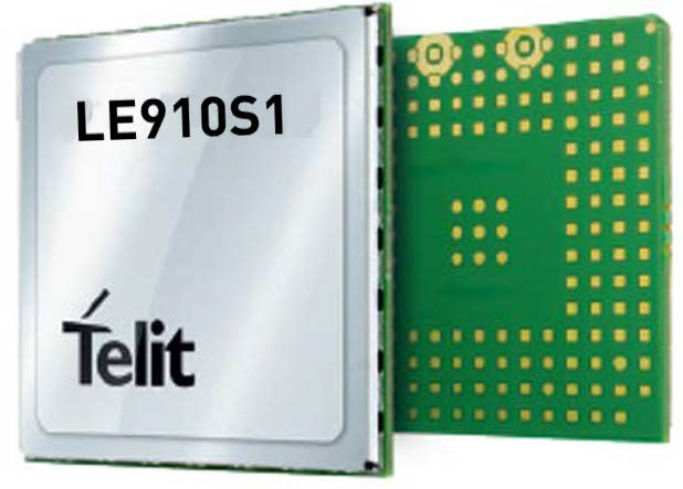
LTE Module
With 2G fallback for Latin America
Photo: Telit
The LE910S1-ELG LTE Cat 1 module is designed for internet of things (IoT) applications in Latin America that need a combination of performance, affordability and voice support in a compact form factor. It provides 2G fallback, making it suitable for areas that have not upgraded to 4G. With an embedded GNSS receiver, the cost-optimized LE910S1-ELG is suitable for tracking applications such as fleet management, stolen-vehicle tracking and recovery, and other mobile IoT applications that need to maintain a reliable connection when moving around in a country, region or multiple regions. The power-saving embedded GNSS receiver enables the use of GNSS positioning even when the cellular modem is switched off.
Telit, telit.com
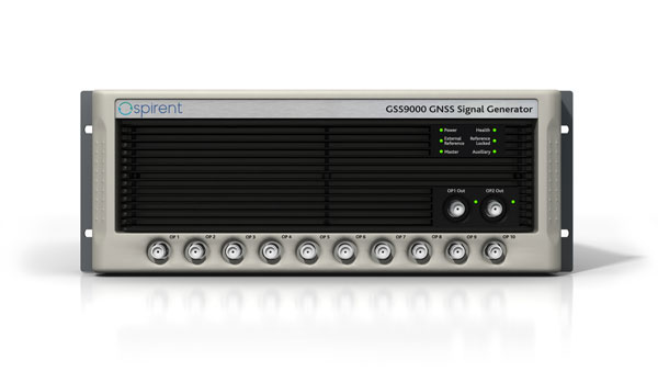
Flex Power
Capability now on constellation simulator
Photo: Spirent
A new positioning, navigation and timing (PNT) test capability commonly referred to as programmable power — or flex power — is available on the Spirent GSS9000 constellation simulator and can be applied to existing scenarios. Flex power is the reallocation of transmit power among individual signals in GPS satellites, providing a countermeasure against GPS jamming. Spirent simulators fully support programmable power for M-code, Y-code and C/A (coarse acquisition) code.
Spirent, spirent.com
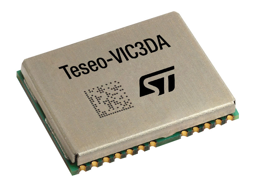
GNSS Module
Automotive qualified with INS and dead reckoning
Photo: STMicroelectronics
The Teseo-VIC3DA is the latest member of the Teseo module family, designed for vehicle positioning. It combines the Teseo III GNSS integrated circuit with the 6-axis MEMS inertial measurement unit (IMU) and dead-reckoning software to provide super-high-resolution motion tracking for advanced vehicle navigation and telematics applications. Teseo III offers robust positioning capabilities by simultaneously receiving signals from GPS, Galileo, GLONASS, BeiDou and QZSS constellations. The module enables competitively priced in-car navigation, fleet management and insurance-monitoring applications.
STMicroelectronics, st.com
PNT Platform
Protects critical infrastructure from GNSS vulnerabilities
Photo: ADVA
The scalable aPNT+ platform meets the latest guidelines for resilient positioning, navigation and timing (PNT), providing end-to-end control and timing network visibility for robust protection against the catastrophic risks that PNT disruption poses to national security and essential assets such as power grids. Even without GPS or GNSS timing, the solution provides an intelligent, end-to-end self-recovery system designed around a three-fold framework, integrating multi-layer detection, multi-source backup and multi-level fault-tolerant mitigation.
ADVA, adva.com
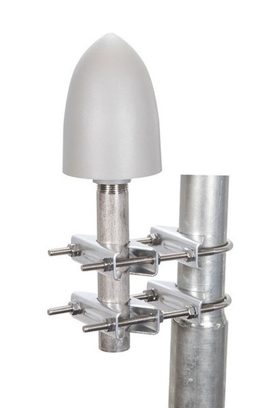
Timing Antennas
IP67-compliant for outdoor and marine environments
Photo: RadioWaves
A new series of GPS/GNSS timing antennas cover the L1 and L5 GPS bands, providing axial ratio and higher accuracy for the reception of satellite timing signals and reference frequencies for enhanced phase synchronization in precision network deployments. Their high gain, low noise figure of 2-dB and high out-of-band rejection allows for use of longer and cost-effective cables for easy and flexible installations. Built-in surge protection supports a wide range of GNSS including GPS, GLONASS, BeiDou and Galileo, as well as Iridium.
RadioWaves, radiowaves.com
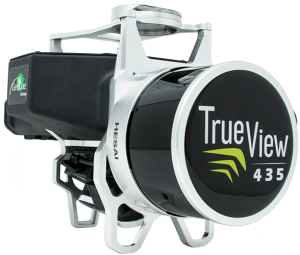
Mapping
Imaging System
Designed for utility and infrastructure mapping
Photo: Geocue
True View 435 is an economical platform for utility-grade mapping, with superior ground-capturing capabilities for lightly vegetated areas. The next-generation compact 3D imaging system has the sensitivity needed for infrastructure mapping. Its position and orientation system is the Applanix APX-15, achieving accuracy of better than 5 cm RMSE and precision of better than 5 cm at 1 sigma.
GeoCue, geocue.com
Long-Range Scanner
Includes integrated GNSS receiver
Photo: Riegl
The VZ-2000i long-range 3D laser scanning system combines user friendliness with fast, accurate data acquisition. The flexible system includes an integrated GNSS unit for a high-accuracy real-time kinematic (RTK) solution. Other peripherals and accessories include a SIM card slot for 3G/4G LTE, WLAN, LAN, USB and other ports. A new processing architecture enables execution of different background tasks onboard in parallel to the simultaneous acquisition of scan data and image data, such as point-cloud registration, georeferencing and orientation via an integrated inertial measurement unit.
RIEGL, riegl.com
Transportation
Vehicle Antennas
Designed for Intelligent connected cars and trucks
Photo: Harxon
Two new GNSS antennas are designed for vehicles equipped with advanced sensors, controllers, actuators and other devices. They are enabled for intelligent information exchanges between the vehicle and everything (V2X), connecting autos with GNSS, 5G, Wi-Fi, ultra-wideband and more. The integrated antennas support dedicated short-range (DSRC) and cellular vehicle-to-everything (C-V2X) communication, embedding a premium GNSS antenna with high gain for consistent and reliable precise positioning service. They also allow for multiple input and output of data to achieve swift internet download speed in 5G networks.
Harxon, harxon.com
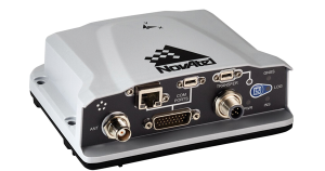
NVIDIA AV Support
Receiver now supported on autonomous platform
Photo: NovAtel
The PwrPak7-E1 GNSS receiver is now supported on the NVIDIA Drive Hyperion autonomous vehicle (AV) development platform. Selected for its robustness and precise position output, the PwrPak7-E1 will be offered with NVIDIA’s autonomous driving test fleets worldwide. Drive Hyperion is a fully operational, production-validated and open AV platform that reduces the time and cost required to outfit vehicles with autonomous driving and artificial intelligence (AI) features. The PwrPak7-E1 also is now compatible with NVIDIA’s DriveWorks v4 software release.
Hexagon | NovAtel, novatel.com
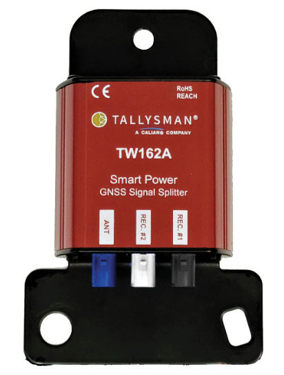
Splitter
Provides signals to two GNSS receivers
Photo: Tallysman
The TW162A automotive-grade smart power GNSS signal splitter supports the full GNSS spectrum: GPS/QZSS-L1/L2/L5, QZSS-L6, GLONASS-G1/G2/G3, Galileo-E1/E5a/E5b/E6, BeiDou-B1/B2/B2a/B3 and L-band correction service frequency band. It offers fail-over and fault-identification features. The splitter accepts power from all attached GNSS receivers; if one receiver fails, the next attached receiver automatically provides power to the splitter and antenna. If the antenna fails and does not draw current, all connected receivers will sense a current draw lower than 1 mA, indicating an antenna fault. The TW162A offers high performance in terms of noise figure, isolation and linearity.
Tallysman, tallysman.com
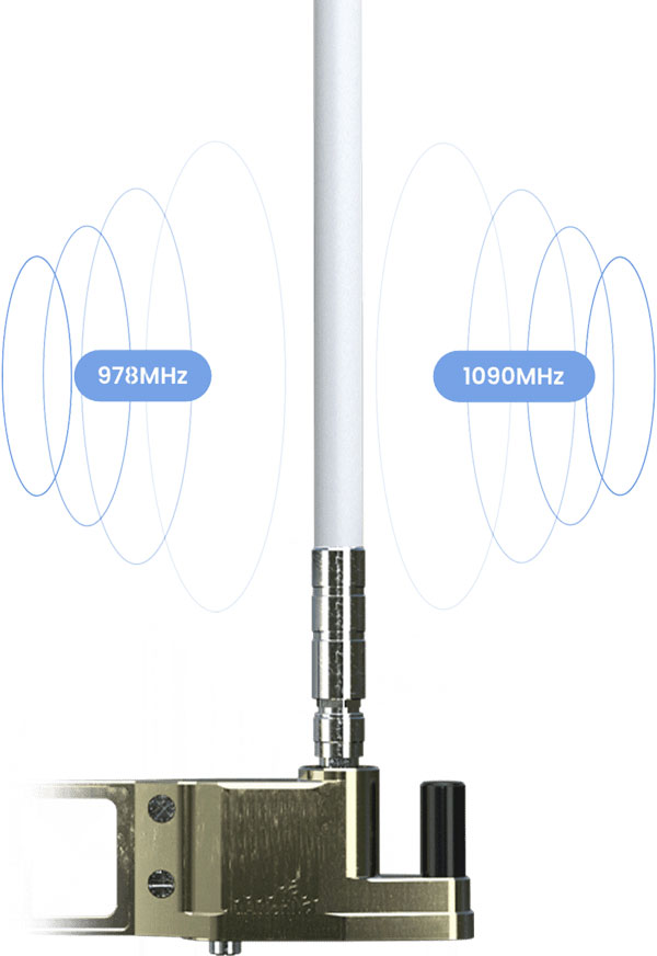
ADS-B Receiver
Enhances airport situational awareness
Photo: uAvionix
The pingStation 3 integrates 978 MHz and 1090 MHz ADS-B receivers, a GPS receiver, an antenna and a power-over-Ethernet (POE) interface into an easy-to-install, rugged weatherproof enclosure. With a selection of non-proprietary and industry-standard data interfaces, such as JSON and ASTERIX CAT 021, pingStation 3 is designed to integrate into a multitude of end-user applications, including airport displays, UAS Ground Control Stations (GCS), Unmanned Traffic Management (UTM) Solutions, and Flight Information Displays (FID). When paired with the VTU-20 airport vehicle ADS-B transmitter, pingStation 3 improves the situational awareness of ATCs and the safety of airport operations by reducing the risk of runway incursions.
uAvionix, uavionix.com
UAV
Defense UAS
Flexible UAV and control software combined
Photo: Ascent AeroSystems
Ascent AeroSystems’ Spirit coaxial unmanned aerial system (UAS) offers a versatile and durable system for mission-critical operations. With a modular, plug-and-play payload design, the Spirit’s open architecture allows operators to add or upgrade software to unlock new operating capabilities without the need to design or develop a new aircraft. Autonodyne’s additive software solution allows the Spirit to perform autonomous tasks either individually or as a team with multiple vehicles, from a single operator and control station.
Ascent AeroSystems, ascentaerosystems.com
Autonodyne, autonodyne.com
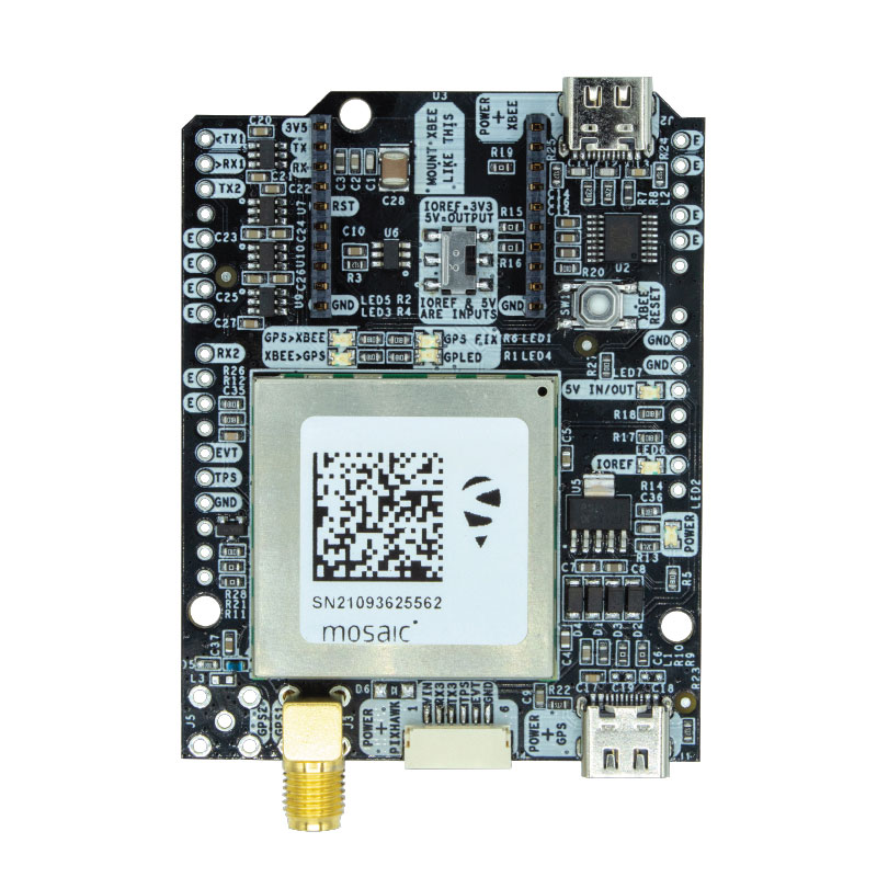
Evaluation Kits
Now include mosaic Septentrio modules
Photo: ArduSimple
Two Septentrio modules are being integrated into ArduSimple’s new evaluation kits — the mosaic-X5 GNSS module and the mosaic-H heading module. The new kits make resilient centimeter-level positioning easily accessible for testing and prototyping. ArduSimple’s kits provide triple-band real-time kinematic (RTK) GPS/GNSS as a plug-and-play solution for the most popular development platforms such as Arduino, STM Nucleo, Raspberry Pi, Ardupilot and Nvidia Jetson. It enables developers of robotics, UAVs and autonomous systems to try out mosaic, a unique module offering the latest high-performance GNSS positioning technology.
Septentrio, septentrio.com; ArduSimple, ardusimple.com
Geospatial Data
Drones as a service
Photo: Beagle
A drone network solution offers on-demand imagery to customers in Germany at resolutions up to 50 times higher than available from commercial satellite data providers. The Beagle M drone and sensors can deliver image data at 1-cm per pixel many times faster than satellites and regardless of cloud coverage. The company’s charging hangars enable quick flights. After completing an autonomous inspection flight (up to 200 km on a single charge), the drone returns to its hangar where it charges for its next mission. The drone takes just 90 minutes to become fully charged, and can then advance to its next mission without any physical contact between operator and aircraft.
Beagle Systems, beaglesystems.com
Radio altimeters are critical in aircraft landing systems. (Getty image). (Photo: guvendemir/E+/Getty Images)
As most GNSS industry insiders already know, the Federal Communications Commission (FCC) has licensed adjacent GNSS L1 protection frequencies to Ligado Networks (formerly Lightsquared) for its nationwide 4G-LTE network.
Many objections emerged as expected this second time around from government agencies, industries and U.S. forces — yet the roll-out is still underway, pending actual interference occurring. This all in an attempt to find communications bandwidth for many emerging commercial radio applications.
Now, as 5G C-Band 3.7–3.98 GHz wireless phone networks begin their FCC approved roll-out, the Federal Aviation Administration (FAA) has apparently lodged an unanticipated objection on the grounds that cross-interference could compromise aircraft radar altimeter and wireless communications that operate at 4.2 to 4.4 GHz in the C-band.
While 5G wireless has already been operating in many parts of the world without reports of interference with aircraft systems, the FAA appears to be taking a more conservative approach to how aviation in the United States should co-exist with the new 5G phone wireless system. The FAA has proposed imposing an exclusion zone around airports for 5G wireless networks — which apparently have already been operating with reduced power in these areas — until cooperative operation has been proven.
Now along comes a new C-band wireless network (SkyLink) aimed at providing high-integrity unmanned aircraft systems (UAS) command and control (C2). The SkyLink company uAvionix has also developed a C-band Control & Non-Payload Communications (CNPC) radio for UAS applications.
Together with Thales, uAvionics recently tested its radio with its SkyLink radio network. The network has been qualified in accordance with the RTCA DO-377 standard for a network management system that monitors network and radio link health, and the radio has been developed to the draft FAA Technical Standard Order (TSO) C-213A to support critical UAS operations.
The network uses new DO-362A-compliant SkyLink C-band radios, integrates certifiable aviation-grade hardware and software, uses frequency agility, and provides critical fault monitoring and control capability. The objective is to obviate the loss of the C2 link with the vehicle, and thereby enable beyond-visual-line-of-sight (BVLOS) operations without an FAA waiver.
It’s unclear whether the emergence of the C-band network — approved by both the FAA and FCC — will play a role in the current phone network interoperability issue. However, uAvionix reports that several sites in the United States and offshore are either rolling out C-band SkyLink networks or evaluating doing so.
North Dakota already has an ISM-band SkyLink network at its UAS test site that will shortly transition to C-band.
The Choctaw Nation in Oklahoma under an FAA program seeks to enable BVLOS operations through a C-band C2 network.
New Mexico State University will use a Skylink C2 network around Las Cruces airport for small UAS (sUAS) operations and testing to overcome anticipated interference from nearby Air Force and Space Force operations.
The Tillamook UAS test range in Oregon has already installed the first ground site of a SkyLink network.
The University of Alaska at the Fairbanks UAS test site will use uAvionics radios for testing large, heavy UAS operations.
In Canada near the Jonesburg airport, a Skylink C2 network will support the safety case for BVLOS pipeline inspection operations for the oil industry.
While many of these new networks are not yet fully online, the use of frequency hopping, safety-monitored C-band, and certifiable transmissions for UAS command and control appears to be moving forward rapidly. Because the FAA is supporting this testing phase, it seems inevitable that large-scale C-band network rollout for UAS C2 will happen eventually.
5G phone networks, wireless UAS command and control, and aircraft safety systems essential for landing will need to find a way to co-exist and provide reliable, sustained service to their respective customer bases. Look for much more to develop in this ongoing tussle between industry groups and agencies who appear to have little in common, other than grudgingly sharing a crowded radio spectrum.
Raytheon BBN-led team recently supported DARPA’s fifth OFFSET program field exercise. (Photo: Raytheon)
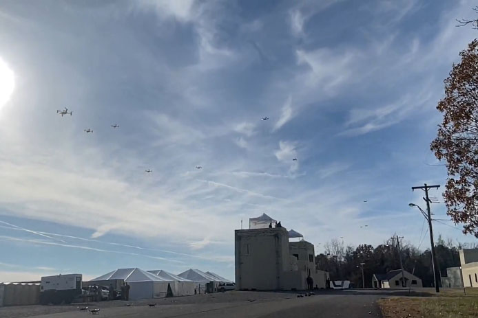
Raytheon Intelligence & Space, a Raytheon Technologies business, recently supported the fifth OFFensive Swarm-Enabled Tactics (OFFSET) DARPA program field exercise.
Using integrated swarm technology developed by a Raytheon BBN-led team, a single operator successfully controlled a swarm — composed of 130 physical drone platforms and 30 simulated drone platforms — both indoors and outdoors in an urban setting. Raytheon BBN provides advanced technology research and development with a focus on national security priorities.
During the exercise, the team used a combination of commercial off-the-shelf and custom-built hardware and software to deliver swarm autonomy. This enabled a single or small group of operators to direct and manage the activities of a large swarm of autonomous air and ground vehicles with minimal training.
“Controlling a drone swarm changes the way an operator or group of operators think about the drones,” said Shane Clark, Raytheon BBN OFFSET principal investigator. “Takeaways from this exercise help inform us of the inflection points between utility and manageability.”
Inexpensive Hardware
A key element of the program is the use of inexpensive hardware. Without the powerful computing and sensing capabilities available in larger more expensive platforms, Raytheon BBN needed to create a broad library of simple tactic building blocks used to create plans to accomplish mission objectives.
Raytheon BBN also designed and configured a scalable, modular and decentralized approach to manage a variety of current and future platforms and missions. Whenever possible, the drones collaborate actively to decide how to accomplish a specific mission most efficiently.
“Our software is smart enough to assign drones with the right capabilities to the appropriate set of tasks,” Clark said. “For example, if the task is to surveil a building, multiple drones will be dispatched, with each surveilling portions of the building. The software considers each platform’s sensor capabilities, and tasks drones with downward-facing cameras to surveil the roof.”
Once the drones are deployed, their collaboration allows them to understand what parts of a building have been explored and where the gaps are. They then autonomously select how to fill in those gaps.
Virtual Reality Interface
To tackle the complexities of human swarm interfaces, the Raytheon BBN team created a virtual reality interface in addition to traditional camera views. It takes feeds from all the swarm assets to create an interactive virtual view of the environment.
“You can look behind the building to access a view of drone locations, for example, and use the virtual reality environment to test and see if your mission is viable,” Clark said. “We also developed a speech interface with the operationally deployed Tactical Assault Kit, or TAK, integration capability that enables the operator to act quickly while maintaining situational awareness over many systems simultaneously.”
The Raytheon BBN-led team includes Smart Information Flow Technologies, or SIFT, and Oregon State University. The team is contracted by DARPA to demonstrate its swarm capabilities during Army Expeditionary Warrior Experiment 2022 taking place in February to March, and hosted by the Army Maneuver Battle Lab.
Seoul Robotics has introduced the Level 5 Control Tower (LV5 CTRL TWR), a mesh network of sensors and computers on infrastructure that guides vehicles autonomously without requiring that sensors be placed on individual vehicles.
The technology is in the early stage of commercial deployment to automate last-mile fleet logistics at BMW’s manufacturing facility in Munich. The system has the potential to transform operations for a wide range of business applications, from vehicle distribution centers to car rental companies and trucking logistics.
Seoul Robotics is a 3D perception solution company using deep learning artificial intelligence (AI) to power the future of mobility,
By placing sensors equipped with 3D perception software around vehicles — traffic lights, buildings and highway overhangs — the system can fully capture the environment and communicate with other sensors and the 4/5G systems that come standard on vehicles.
The LV5 CTRL TWR collects all the 3D data, and then automates vehicles accordingly using V2X communications.
“Level 5 mobility has been proven to be more challenging to achieve than expected, until now,” said HanBin Lee, CEO of Seoul Robotics. “LV5 CTRL TWR has massive potential to fuel autonomous mobility, and we are thrilled to continue expanding upon the implementation of this technology with BMW and other partners.”
“Ultimately, these systems will be deployed in additional public and commercial settings, powering aspects of our everyday lives, such as autonomously navigated parking and public transit,” Lee said. “With LV5 CTRL TWR, this future is closer and more accessible than ever.”
The collaboration with BMW leverages hundreds of connected lidar and 3D sensors on infrastructure to automate newly manufactured vehicles within factories and vehicle distribution centers without any human involvement. By making this process autonomous, automakers like BMW can increase operational efficiencies and safety within automotive logistics.
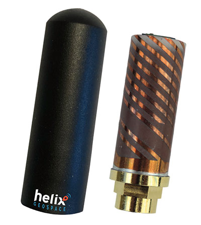
Helix builds precision GNSS antennas that enable product designers to create small, accurate positioning, navigation and timing (PNT) synchronization products that defend against vulnerabilities and threats. Helix is also developing its antennas to provide navigation for autonomous vehicles.
Helix’s patented DielectriX antennas are targeted initially to receive PNT signals from GNSS (GPS, Galileo, GLONASS, Beidou) constellations, and the Satelles STL (Satellite Time and Location) signals delivered over the Iridium constellation as well as Iridium’s voice and data network.
Future antenna variants will support low-Earth orbit (LEO) PNT services being planned and built by private companies, as well as government agencies, the company said.
DielectriX antennas discriminate true satellite signals from multipath signals, interference and jamming, delivering high performance in a compact and rugged form factor. Helix’s customers include defense, automotive, aerospace and critical infrastructure companies.
Helix previously raised £2.5 million from UKI2S and angel investors, and has participated in Wayra UK’s Intelligent Mobility Accelerator programme and Seraphim Capital’s Space Camp Mission 6. Helix also received additional grant funding for advanced antenna development from the European Space Agency, and for anti-jamming/spoofing technology from UKI2S.
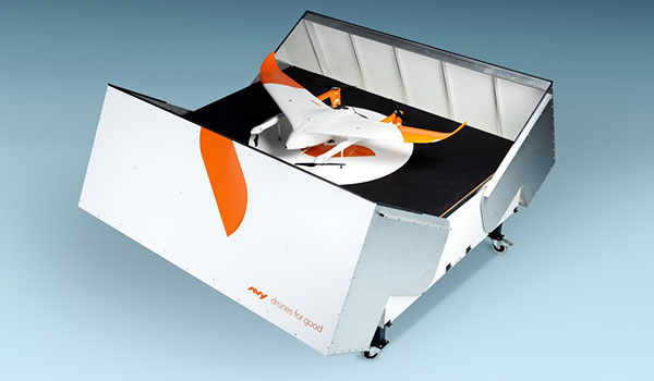
The Avy Aera departs from its docking station within minutes, shortening response times and reducing costs for first responders. (Photo: Avy)
Dutch company Avy has launched its Drone Response Network, combining docking stations with autonomous aircraft that have vertical take-off and landing (VTOL) capabilities.
The network offers drone coverage in a certain area, enabling instant deployment to support medical deliveries or emergency services during critical incidents.
First flights are expected to take place in the first quarter of 2022.
The network uses the Avy Aera autonomous drone that can carry up to 3 kg of medical goods over a distance of 100 km. It can operate year round, in rain and winds up to 45 kph, and is designed to meet the latest European Union drone regulations and United Nation requirements for aerial transport of medical goods.
For medical delivery, the drone is equipped with Aera’s Medkit, which has a four-liter capacity and is fitted with sensors for immediate assessment. Medical products remain cooled at 2-6 degrees for at least 100 minutes in an ambient temperature of up to 40° C.
The Avy Drone Response network is suitable for both urban and rural areas, delivering medicines, blood products, vaccines and other medical applications safer and twice as fast as road transportation, and is more environmentally friendly. It is expected to make a substantial contribution to achieving the goal of connecting hospitals and laboratories by air by 2023.
The Avy Aera can also be integrated with a high zoom RGB and thermal camera system and used to quickly detect wildfires, spot people in distress at sea, monitor oil spills and assess the situation on the ground.
 The Navigation Sensor Switching in Hostile Environments (NAV-SSHE) project aims to design, prototype and demonstrate new solutions for positioning, navigation and timing using 5G plus GNSS for critical applications in hostile environments. NAV-SSHE is supported by the European Space Agency (ESA).