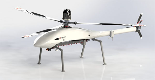
The Velos UAV helicopter has passed field tests to become the first single-rotor helicopter supported by UgCS software, according to UgCS maker SPH Engineering. UgCS now enables Velos helicopter professionals to use Velos for photogrammetry and lidar drone surveying missions.
UgCS is now able to support the twin-engine telemetry providing input for a UAV. Its newly created Telemetry Viewer can handle extensive telemetry from such complex drones. This allows for optimal flying of the Velos helicopter with a fully redundant twin-motor design and double key components.
UgCS allows for the control and monitoring of one or multiple Velos helicopters on a single mission in both single and multi-operator modes.
Photo: Velos UAV
The field tests were initiated and conducted by GeoInspect, the first company to use c with its Velos helicopter. The new solution allows professionals to fine-tune projects, resulting in maximum performance and very high usability. One of the projects was a fully autonomous test flight with UgCS.
“GeoInspect has been performing lidar surveys successfully with UgCS for many years,” explained Bart Zondag, GeoInspect founder. “Having started with the M600 model, UgCS is now used to support single-rotor UAVs. We have already delivered a Velos V2 with UgCS to one of our customers to the EU Nordics to perform lidar forestry surveys.”
Learn more about the solution by joining a free Zoom webinar on March 4, 2021.
The acquisition will expand Verizon’s robotic capabilities to power the future of robotic automation for enterprise customers
Verizon has entered into a definitive agreement to acquire incubed IT, the creator of a software platform providing autonomous navigation tools to administer, manage and optimize mixed fleets of robots in industrial settings.
“This acquisition further demonstrates Verizon’s commitment to developing new and innovative businesses and use cases leveraging the power of 5G,” said Rima Qureshi, chief strategy officer at Verizon. “Mobile robot orchestration is a real and emerging challenge faced by enterprises today. By integrating incubed IT’s autonomous software with Verizon’s 5G platform, we will have the ability to power robotic automation at scale. This will create new opportunities for enterprise customers to better and more effectively monitor and optimize their business processes.”
Upon closing and as Verizon continues to expand its 5G coverage, capacity and mobile-edge compute capabilities, incubed IT’s autonomous software will enable enterprise customers to gain new efficiencies as they scale their autonomous mobile robot fleets.
Incubed IT’s award-winning software enables robots to localize and navigate autonomously and can be easily integrated into nearly any mobile robot. Their products include:
Smart Shuttle Navigation Toolkit: Transmits near real-time data to navigate autonomous mobile robots (AMRs)
Fleet Management Server: Manages AMR Fleet & Routing Operations
Data Monitoring and Analytics: Near real-time monitoring and advanced
reporting
“Incubed IT’s next-generation software and autonomous fleet management server are foundational components for the future of terrestrial robotics,” said Elise Neel, vice president of Verizon New Business Incubation. “When we combine incubed IT’s capabilities with the reliability, responsiveness and vast capabilities of Verizon’s 5G platform, we will enable faster, less expensive and more effective adoption of robotic automation for enterprises everywhere.”
Incubed IT’s autonomous navigation software features include:
No need to specify transport paths up front
No predefined paths
Instant rerouting
Obstacle avoidance
Safe operation in areas with other vehicles and humans
Incubed IT’s employees will join the Verizon New Business Incubation team, whose mission is to scale new automation businesses, fueled by the inherent orchestration power of 5G. The incubed IT team will continue to drive development, sales and support for its customers and suite of products across a fleet of diversified robotic partners.
“We are proud of all the incubed IT team has accomplished to get us to this point, and we look forward to expanding on our successes and capabilities,” said Stephan Gspandl, incubed IT CEO. “By joining the Verizon team, we have the opportunity to bring our software to broader audiences and to help create the future of robotic automation.”
The transaction is subject to customary closing conditions and is expected to close in the first half of 2021.
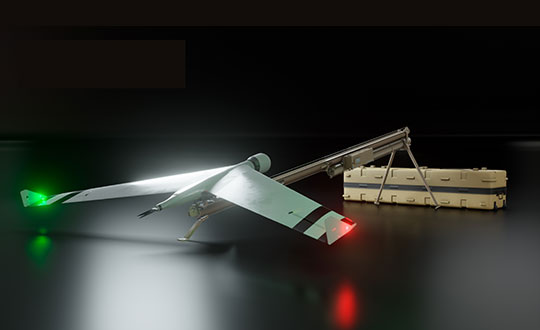
Zala Aero Group unveiled the ZX1, a new hybrid unmanned aerial vehicle (UAV), at the 2021 International Defense Industry Exhibition (IDEX) and Conference, which opened on Feb. 21 in Abu Dhabi.
The new drone has vertical-takeoff-and-landing (VTOL). According to Zala, it combines the best qualities of fixed-wing and multirotor types of UAVs; its configuration can change depending on the conditions of the performed task.
Ease of operation allows the UAV system to reduce the operator’s role, decrease the amount of equipment used when performing a flight mission, and fully automate flight processes of the UAV.
The ZX1’s onboard computer uses artificial intelligence, which makes it possible to process data in full high-definition, and transmit HD video and photos via encrypted communication channels to the GCS, ensuring the effectiveness of monitoring even before the aircraft lands.
The VTOL design makes it compatible with existing ZALA payloads, and also allows the installation of additional surveying equipment. It can be used to perform air monitoring for the fuel and energy sector and search-and-rescue operations from sites in urban environments.
Zala Aero Group, founded in 2004, is a Russian developer and manufacturer of unmanned aerial systems, payloads and mobile systems. It is now part of Concern Kalashnikov. Its main products are reconnaissance unmanned systems and digital solutions. Currently, more than 2,000 of Zala UAS operate within Russia. Areas of application are the protection of state borders, reconnaissance and rescue operations, monitoring of high-risk facilities and emergencies.
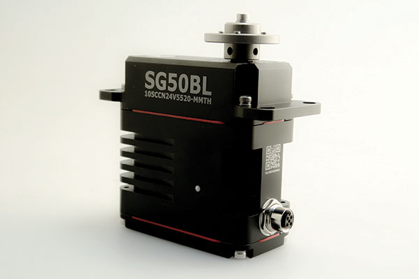
The SG50BL, designed with robust steel gears and a high-performance brushless motor, is capable of operating at a voltage range of 18 to 32 volts, the company said.
The actuator features a programmable digital circuit with a MOSFET amplifier; a BLDC motor; a magnetic encoder position sensor; five hardened steel gears low gear backlash (less than .5°); four ball bearing supported output shaft; nine needle bearing supported idlers; rugged anodized aluminum alloy case; and an IP68 waterproof rating.
The SG50BL also is capable of 360° proportional rotation and boasts T4131012051-000 TE connectivity. It includes CAN 2.0 A/B or UAVCAN control options, customization and modification options, and custom connector options.
Founded in 1973, Hitec designs and produces high quality actuators and radio control components for a variety of applications and demands.
It’s only a few weeks into the new year, yet there’s plenty happening in “UAV land” already. I expect another year of innovations, novel developments and groundbreaking firsts in unmanned aircraft.
This month’s question: What’s a Skyborg? The U.S. Air Force (USAF) has awarded contracts to Kratos, Boeing and General Atomics to prove their approaches to the UAV program.
All three have fielded existing, company-developed drones which are intended to fly alongside and be controlled by the latest frontline U.S. fighter aircraft. The idea is to have expendable force-multiplier unmanned aircraft support the capabilities of high tech, hugely expensive aircraft in order to undertake perhaps more risky missions, with the potential improvement acceptable versus unacceptable losses.
Flying alongside frontline fighter aircraft, these jet-powered unmanned aircraft could undertake more risky close support parts of the mission, where loss of the UAV might be more likely, while the manned aircraft remains outside the high-risk envelope. Hence the term attritable is now being applied to these unmanned accompanying vehicles, which are intended to have a reduced cost profile so that loss of the UAV might be more tolerable.
The Air Force Life Cycle Management Center (AFLCMC) has awarded Skyborg Vanguard Program contract amounts to Boeing ($25.7 million), General Atomics ($14.3 million) and Kratos ($37.8 million) for initial prototyping. All appear to have Skyborg prototypes in development.
Kratos has subsequently announced other contract modifications related to the U.S. Air Force Research Laboratory (AFRL) Low Cost Attritable Aircraft Technology (LCAAT) program.
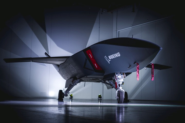
Boeing will offer a variant of the Airpower Teaming System (ATS) drone being developed in Australia for the Australian Air Force. Engine runs and initial taxi tests were recently completed, however the program went into a short hiatus at the end of 2020 because of high COVID-19 infection rates in and around Sydney.
Boeing will offer a variant of the ATS drone being developed for the Australian Air Force. (Photo: Boeing)
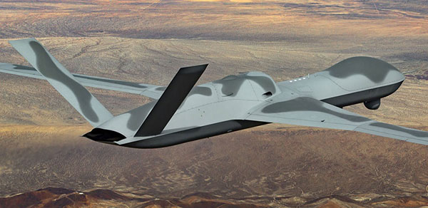
General Atomics Aeronautical Systems Inc. (GA-ASI) is in the process of modifying two company-owned Avenger UAVs to incorporate upgraded datalinks and the Skyborg System Design Agent (SDA) software. Flight trials will investigate Artificial Intelligence capability for autonomous control of the UAVs while operating alongside manned aircraft – with the object of demonstrating that “a mix of manned and unmanned aircraft can communicate, collaborate, and operate together,” said David R. Alexander, president of GA-ASI.
General Atomics Avenger unmanned aircraft. (Photo: GA-ASI)
The jet-powered Avenger aircraft has been under development and evaluation for more than 10 years so it is well characterized, and its performance as a UAV is already understood.
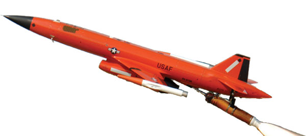
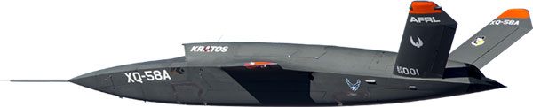
The XQ-58A Valkyrie UAV has benefited from earlier generations of Kratos high-speed jet-powered target systems — something none of the other Skyborg competitors have in their bag of tricks. Kratos has been providing high-speed target drones to the military for a number of years, so jet powered drones are something they have been developing and fielding for a long time.
The Valkyrie UAV was developed under the LCAAT program to demonstrate unmanned low-cost capabilities, and to fly as a stealthy companion to manned aircraft. It is intended to carry internal and wing mounted weapons. The turbine division of Kratos is also investigating lower cost jet engine options for attritable UAVs.
Meanwhile, continuing developments in detect and avoid (DAA) are progressing, moving towards a solution for one of the main problems holding back integration of unmanned aircraft into controlled airspace.
A number of these solutions are based on ADS-B or Automatic Dependent Surveillance Broadcast, whereby the UAV location – usually position provided by onboard GPS — is transmitted at a regular interval by an equipped UAV. So any similarly equipped manned or unmanned aircraft can receive the ADS-B signal, has knowledge of where such flying obstacles might be and is therefore able to avoid a potential collision.
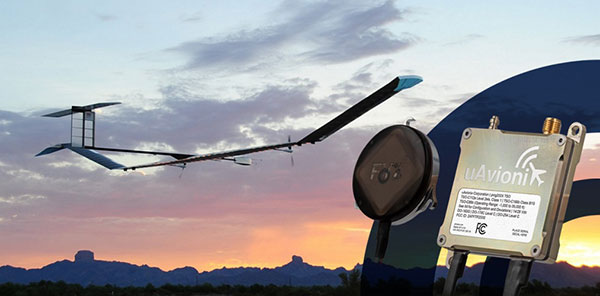
And for pseudo-satellite applications like the Airbus Zephyr which must transition between low-level airspace and the stratosphere, having on-board certified ADS-B is essential so that other aircraft and FAA air-traffic control have full visibility of such a delicate airframe which is lacking great maneuverability during climb-out, on station at altitude and during descent.
Zephyr pseudo-satellite UAV with uAvionix ADS-B transponder and GPS. (Photo: uAvionics)
Since Zephyr transitions through Class A airspace, the manufacturer Airbus decided that it should be equipped with an ADS-B transponder and GPS source which had undergone FAA recognized qualification testing and which meets known Technical Standard Order (TSO) requirements.
The equipment also needed to be small and use little power — at 70 grams and using only 2 watts, the uAvionix ping 200X transponder and truFYX GPS provide high power (54 dBm), high integrity transmissions of ADS-B and transponder mode data to Air Traffic Control (ATC) and other suitably equipped aircraft.
Zephyr is an all-electric vehicle, using sunlight to derive power from large photo-voltaic arrays which cover its upper surfaces. Batteries store surplus energy which is not consumed during daylight and provide power in order to maintain aircraft station through the night hours. From a perch at around 70,000ft, Zephyr is apparently focused on Earth-observation capability with payloads envisaged to include Electro Optical, Infrared, Hyper spectral, Passive Radio Frequency (RF) Radar, Synthetic Aperture Radar (SAR), plus Early Warning, Lidar and Automatic Identification System (AIS).
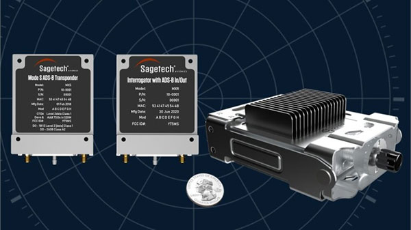
The Hover DAA solution. (Photo: Sagetech)
“Sagetech is another DAA supplier which is currently working with both fixed and rotary wing UAS customers who are incorporating DAA systems in their design and type certification projects,” said Tom Furey, CEO of Sagetech. “Sagetech is providing regulatory guidance, transponders and interrogators, and system design to ensure these UAV systems in development will satisfy the anticipated certification requirements. Sagetech itself, through technology development and partnerships with companies including Hover Inc., expects to offer a complete DAA prototype system by the end of this year.”
So, lots of progress towards Skyborg drone teaming systems with $78min awards by the Air Force Life Cycle Management Center from an anticipated budget of around $400m, while certified Detect and Avoid solutions help move commercial drones towards potential regular flight in controlled airspace.
New tech can track vehicles, drones and cargo remotely within centimeters — key to safe adoption of autonomous vehicles, flying objects and machinery
Vodafone has successfully used new precision positioning technology to remotely track a vehicle to within 10 centimeters of its location, an improvement of more than three meters compared to its current system.
Vodafone is working in partnership with Sapcorda, using Vodafone’s global internet of things (IoT) platform, which has 118 million connections worldwide.
Vodafone expects the technology to enable applications that warn autonomous trucks of obstacles, tell first responders the position of critical medical drones, and give operators the precisely location of important cargo.
Pinpoint accuracy is critical to the acceptance and mass adoption of autonomous vehicles on the road and in factories, airports, dockyards and any site where machines are in motion. A matter of centimeters can be crucial to ensuring the safety of passengers on a driverless bus, or knowing the precise location of a medical drone. a
The tracking technology will also allow an autonomous truck to mind other road users, including cyclists, whose e-bikes can automatically transmit their position and intended direction of travel.
“We might not be able to locate a needle in a haystack yet, but we are getting close,” said Vodafone Business Platforms and Solutions Director Justin Shields. “What we can do now is take new digital services like this one, integrate it with our global IoT platform and fast networks, and offer it securely at scale to many millions of customers.
“Our in-building 5G and IoT services already allow manufacturing plants, research laboratories and factories to carry out critical, and often hazardous, precision work with robots. Now we are applying the same levels of accuracy to the outdoor world.”
Vodafone is redefining its network and technology on a Telco as a Service (TaaS) model. It makes key network capabilities available through common APIs in a cloud platform to deliver new software, video and data applications at scale, in addition to gigabit-capable connectivity.
Vodafone said the TaaS model will benefit large enterprises, improving their ability to locate critical assets, precisely align machines such as driverless trains at platforms, and let farmers, airports, and fleet operators know the exact whereabouts of their autonomous vehicles.
Vodafone IoT-enabled vehicles, machinery and devices — when linked with Sapcorda’s comprehensive network of GNSS receivers and augmentation technology — improves location accuracy by correcting for things like the curvature of the earth, atmospheric delays and clock differences of global positioning satellites. This offers corporations hyper-precise positioning that they can use to ensure a safe environment for their employees, their customers, the public and their machines.
Combined with video and onboard diagnostics, the technology will also allow vehicle operators to carry out accurate location-sensitive remote inspections and even pause machines such as grass cutters on public footpaths when they encounter people.
PPP-RTK method. Vodafone is adopting the precise point positioning – real-time kinematics (PPP-RTK) method with ground-level GNSS stations to achieve the best error correction. GNSS signals are processed and GNSS corrections are sent out to enhance the position accuracy of the vehicles receiving them.
Vodafone is able to equip any number of vehicles with an in-built IoT SIM, and deliver the positioning data at speed using its gigabit-capable networks.
Vodafone recently put this to the test by tracking in real-time the exact lane that vehicles were traveling in during a combined journey of more than 100 kilometers in varying weather conditions.
Sapcorda provided the data feed, which enabled the GNSS signal to be corrected, to deliver the critical-level of positional accuracy. A precise positioning service complements the existing asset tracking and fleet telematics solutions already provided by Vodafone Business for enterprise customers across 54 countries.
French ministry for Armed Forces selects Airbus Survey Copter Aliaca fixed-wing drone systems to equip its ships
Airbus Defence and Space mini UAS subsidiary Survey Copter signed a contract with French DGA Armament general directorate to provide the French Navy with 11 systems, (22 aircraft), of the electrically powered fixed-wing Aliaca maritime version UAS (officially called SMDM / “Systèmes de Mini Drones aériens embarqués pour la Marine” by French authorities), including training and integrated logistic support. First deliveries are expected in 2021.
“We are honored to contribute to the missions of the French Navy which we will support with the highest standards of quality and reliability,” said Nicolas Askamp, head of Survey Copter/Airbus Unmanned Aerial Systems. “This new contract strengthens Survey Copter’s position as a global key player for maritime mini UAS.”
The Aliaca maritime UAS is a high-endurance versatile system allowing up to 3 hours missions over a 50 km (27 Nm) range, perfectly adapted to maritime missions with high gyro stabilized EO/IR payload performances and qualified to operate in severe environmental conditions.
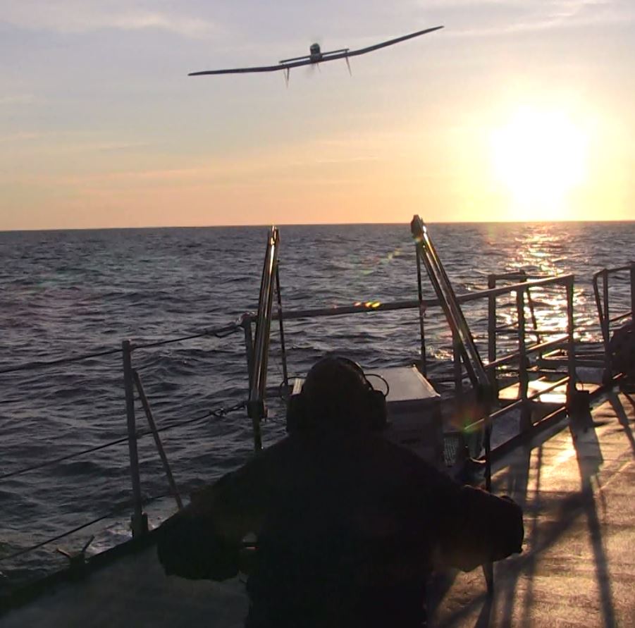
The Aliaca SMDM is catapulted from a ship deck. (Photo: Airbus Defence and Space)
Launched by catapult, the Aliaca maritime UAS concludes its flight by landing automatically using a dedicated net landing solution. With a length of 2,2m and a wingspan of 3,6m for a maximum take-off weight of 16 kg., the Aliaca maritime UAS benefits from a powerful yet silent electric motor. The system can be deployed easily and rapidly in less than 15 minutes by 2 operators only.
Similarly, the user-friendly ground control station enables the operator to constantly monitor the automatic flight of the UAS while receiving in real-time day and night images and AIS (Automatic Identification System) data gathered by its on-board sensors.
It is designed to conduct several types of missions around the ships, including increasing the understanding of the tactical situation, control of illegal operations at sea, search-and-rescue, traffic monitoring, pollution detection, tracking of any suspicious behavior in the ship environment and coastal surveillance.
This light on-board aerial solution gives the opportunity to vessels, traditionally not equipped with aerial assets, to enhance their tactical ISR capabilities, support decision making and reactivity in operations.
The Aliaca maritime UAS can easily be integrated on board any ships, with or without helicopter landing-deck, and its small logistic footprint enables operations and storage on board smaller sized ships. Its integration does not require heavy on-board modification nor storage of specific fuel.
The result of 10 years of R&D investments and on-board experimentations, SURVEY Copter’s off-the-shelf Aliaca maritime UAS is a robust and resistant system to the corrosive maritime environment, an adapted solution to the electromagnetic constraints on board, and benefits from an efficient net recovery system, fully automated, meaning that no human action is required during the recovery phase.
The May virtual conference will feature live keynotes and education, interactive roundtable discussions and networking sessions. It also will include exhibits from leading technology companies and service providers. All sessions will be recorded and made available on-demand to attendees for 90 days following the event.
The August in-person event will feature a new program of keynote speakers and educational sessions, safely facilitated networking opportunities, and an expanded exhibit hall to experience the latest technology innovations and solutions.
The theme of Xponential 2021 is “Assured Autonomy,” which refers to the process, methodology and guiding principles for ensuring unmanned and autonomous systems will be safe and practical options, able to repeatedly perform the operations they are designed for and be seamlessly integrated into society at scale. According to AUVSI, this theme supports the event’s legacy of convening experts across markets and domains to advance the market for all things unmanned.
“As the global stage for all things unmanned, AUVSI Xponential 2021 is where you’ll join a community of end users, technologists and policymakers working together to fulfill this vision,” AUVSI said. “The series will support its mission to convene the unmanned and automated systems community to accelerate innovation and market adoption of the related technologies.”
AUVSI is a non-profit organization dedicated to the advancement of unmanned systems and robotics. It represents corporations and professionals from more than 60 countries involved in industry, government and academia. AUVSI members work in the defense, civil and commercial markets.
Check out GPS World‘s coverage of AUVSI Xponential from 2015, 2016, 2017, 2018 and 2019.
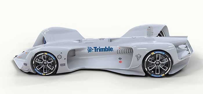
Trimble has partnered with Roborace, an autonomous racing series with electric-powered vehicles. As part of the alliance, Roborace will use Trimble’s Applanix POS LVX GNSS-inertial systems in its next-generation autonomous race cars for season one of the championship, which begins in September 2021.
As part of the technology and marketing alliance, Trimble will serve as the Official GNSS-Inertial Positioning Technology Partner and enable Roborace’s engineering team to leverage Trimble resources such as technology, services and expertise that it provides across a wide variety of industries and applications, Roborace said. Trimble also will utilize Roborace’s media platform in its global marketing initiatives.
Image: Roborace
“We are thrilled to be working with Roborace, the world’s first extreme competition of racing teams developing self-driving artificial intelligence for autonomous driving systems,” said Louis Nastro, director of land products at Applanix. “Trimble systems, software and solutions for positioning and orientation are designed for pinpoint accuracy, efficiency and ease of use, and are perfectly suited for autonomous vehicle applications such as Roborace.”
Roborace also looks forward to the partnership.
“At Roborace we are always looking for the best technology to incorporate into our cars and we’re thrilled to announce this alliance,” said Chip Pankow, chief championship officer at Roborace. “Trimble is a leader in the field and the small size and accuracy of the POS LVX is a perfect solution for us. These GNSS-inertial systems will be utilized in all vehicles participating in the Roborace championship.”
Roborace was created to accelerate autonomous software development by pushing the technology to its limits in a range of controlled environments. It also aims to educate and inform the world about autonomous driving. In 2019, the series held six events that drove more than 36 million multi-channel video views.
Designed to operate under the most difficult GNSS conditions found in urban and suburban environments, Trimble’s Applanix POS LV enables accurate positioning for road geometry, pavement inspection, GIS database and asset management, road surveying, vehicle dynamics and autonomous vehicle systems. POS LVX is a configuration of POS LV housed in a robust, rugged enclosure and easily incorporated into small vehicles, autonomous platforms and tight spaces of all types, Trimble said.
2,300-acre Shell Deer Park Refinery provides complex testbed for aerial inspections and incident response
Photo: SimonSkafar/E+/Getty Images
DJI is partnering with Shell Oil Company to create, test and deploy DJI drone technology at its Deer Park Manufacturing Complex to improve efficiency and worker safety during industrial inspections and emergency incident response.
The Shell Deer Park drone team adopted DJI drones in 2016 to reduce the need to work at height while improving safety and cutting the cost of inspections in the process. As a Solution Development Partner, Shell will work with DJI to develop and test advanced drone solutions, like the DJI Matrice 300 RTK, that allow workers to automate required inspections of critical infrastructure like flare tips and floating roof tanks whose condition and activity are difficult to assess from ground level.
“As one of the world’s largest energy companies, Shell has provided us with valuable insight into the unique challenges of conducting aerial inspections at one of its largest facilities where infrastructure exceeds the height of 250 feet off the ground,” said Cynthia Huang, until recently the director of business development at DJI. “Through our collaboration, DJI will receive valuable first-hand insight into the complexities of deploying drone technology at a world-class refinery, and co-develop new product features like AI Spot-Check that will allow Shell and other innovative energy companies to use drones to safely and easily conduct required inspections of critical infrastructure.”
“Shell Deer Park is excited to become a Solution Development Partner with DJI as we continue to adopt drone technology,” said Shell Deer Park’s Chief Drone Pilot John McClain. “Through this partnership, Shell Deer Park will have access to some of the most advanced drone technology from DJI to help elevate workplace safety and improve efficiency across our operations in the world’s largest industry.”
Fusing Automotive Radar and OBD-II Speed Measurements with Fuzzy Logic
SYN·ER·GY/ˈsinərjē/ noun: the interaction or cooperation of two or more organizations, substances, or other agents to produce a combined effect greater than the sum of their separate effects; from the Greek, “working together.” That is how the Oxford Dictionary defines this useful property that we often apply to business activities and other human interactions. But it can just as well describe the basis of an apparatus such as a navigation system that consists of several devices working together to produce a safer and more accurate result.
We all know that GPS or any GNSS for that matter doesn’t work everywhere all the time. For example, in built-up areas, signals can be blocked and reflected by buildings leading to positioning errors or complete outages. That is why it is quite common nowadays to combine a GNSS receiver together with an inertial measurement unit or IMU (often in the same package) to produce a more reliable solution for continuous navigation. But IMUs drift and so during an extended GNSS outage, the fidelity of the position reported by the GNSS plus IMU system will degrade with time. And so additional sensors must be added to the mix to improve the reliability of the navigation system. LiDAR, cameras, altimeters and so on have all been used severally or individually to augment the basic GNSS plus IMU combination. Self-driving cars, for example, use multiple sensors to provide safe navigation under specific conditions. Such specialized systems are quite expensive and so we might ask: Can the basic combination of GNSS and an IMU (or some of its components) be augmented by measurements already available in most vehicles or provided easily and inexpensively by equipment add-ons?
Yes. One measurement that helps is the forward speed of the vehicle. This is available from the vehicle’s on-board diagnostics computer system that tracks and regulates a car’s performance. Car manufacturers have adopted a standard for reporting data, the latest version of which is OBD-II. It is easy to interface to the OBD-II connector in a vehicle and extract the speed measurements – the same measurements displayed by the vehicle’s speedometer. Another potential source of speed measurements is the radar in most modern vehicles used for adaptive cruise control. That measurement is hard to acquire and has other limitations. But the idea to use radar as an input to a navigation system is a good one and easily obtained and installed radar units can be used instead.
But how do you optimally combine all of these sensor readings to produce reliable navigation? In the Innovation article this month, we take a look at how fuzzy logic can be used to get a reliable speed estimate, how that can be combined with accelerometer and gyroscope measurements to get position, velocity and attitude of a vehicle and, lastly, how that can be combined with GPS-derived position and velocity in an extended Kalman filter to produce an integrated navigation solution. Now that’s synergy.
Abosekeen
Standard land vehicles and self-driving cars have acquired precise navigation solutions to improve safety and assist drivers. GNSS is used as the primary source of the navigation solution for such applications. However, when driving in environments such as urban canyons, tunnels, or under bridges, GNSS signal reception deteriorates. Worse, it may suffer from a full outage. Because of this, we need a supplemental or backup system, such as an inertial navigation system (INS). The INS provides a complete navigation solution, and it is not affected by signal deterioration or jamming. GNSS/INS integration can achieve better accuracy than GNSS alone. However, such efficiency cannot be maintained during extended GNSS outages, especially with low-cost and commercial-grade inertial sensors for the INS. This drawback principally occurs because the INS solution suffers from accumulated error growth over time. This error causes path or trajectory drift, which becomes significant in the long term.
The fusion between an INS and a GNSS-based system provides a more robust solution than each system alone. In particular, INS/GNSS integration requires both systems to provide the vehicle with an accurate solution. However, when the vehicle is in challenging environments, the GNSS receiver cannot successfully update the integration filter, leaving the INS as the only source for the solution. When a GNSS outage is prolonged in some extreme situations, the solution quality deteriorates rapidly from INS drift. In particular, when using a micro-electromechanical system (MEMS) based inertial measurement unit (IMU), the drift rate significantly increases.
Several approaches have been introduced to overcome such drawbacks. Our reduced inertial sensor system (RISS) concept can be a replacement for the INS in land vehicle and ground robot applications. RISS can provide a complete navigation solution with fewer sensors than a standard INS. It is easily implemented for common land or self-driving vehicle navigation because it uses the vehicle’s on-board diagnostics standard II (OBD-II) device to determine the vehicle’s forward speed. INS requires two integration steps for positioning, but using the OBD-II speed measurements in the RISS mechanization requires only one.This reduction reduces the drift rate because it limits error accumulation from the integration process.
RISS depends mainly on OBD-II speed measurements to provide the land vehicle forward velocity. Unfortunately, these speed measurements are vehicle-specification dependent. Furthermore, these speed measurements are vulnerable to several types of error sources that can be categorized as deterministic (systematic) and non-deterministic (non-systematic). Deterministic errors come from wheel-diameter changes due to variations in temperature, pressure, tread wear, speed, unequal wheel diameters between the different wheels, inefficient wheelbase (track width), limited resolution and sample rate of the wheel encoders. Non-deterministic error sources include wheel slips, uneven road surfaces and skidding. Both groups of error sources negatively affect the velocity, traveled distance and heading estimations using the speed measurements from the OBD-II device.
Accordingly, we have made several RISS modifications to enhance performance, such as integration with a GPS receiver by enhancing the system design matrix for the integration filter. Moreover, an azimuth measurement update from magnetometers was added to the RISS/GPS integrated navigation system to provide azimuth updates during GPS outage periods, so the system can ensure more reliable positioning accuracy in challenging GNSS environments. Furthermore, we introduced a radar-based RISS to overcome OBD-II speed measurement errors. With this system, we demonstrated the superiority of using a frequency modulated continuous wave (FMCW) radar as a speed source instead of the one based on the OBD-II device. Automotive adaptive cruise control (ACC) mainly uses the Doppler measuring technique to measure the target’s (the vehicle ahead’s) relative distance and velocity. The primary radar unit’s radiation pattern is supposed to be a narrow beam to avoid other moving objects. Unfortunately, clutter affects forward-looking radar-collected data. Besides, extracting the onboard vehicle’s speed is difficult primarily because of the radar installation position.
We improved the use of ACC by modeling the linear and non-linear error components with Fast Orthogonal Search as a non-linear system identifier. This provided a more precise solution during outages extending from 60 seconds to 10 minutes. Furthermore, vehicle positioning using ACC was enhanced by extracting the primary and target vehicles’ relative distances under specific rules in urban canyons. These results encouraged us to introduce a fusion between the RISS and ACC, developing a more robust navigation system that relies on more than one sensor type.
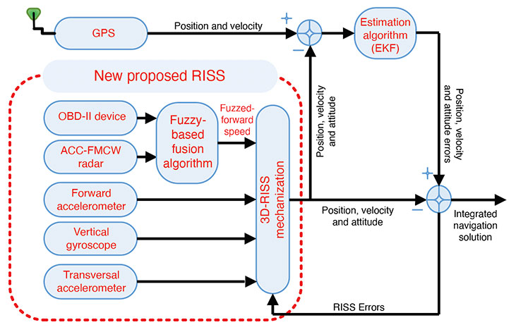
In this article, we propose a smart fusion technique to produce more accurate velocity information from both the Doppler radar and the OBD-II speed measurements. Our new RISS mechanization for land vehicle navigation uses the fused speed from the radar and the OBD-II device with a vertical gyroscope and two transversal accelerometers.
3D-RISS MECHANIZATION
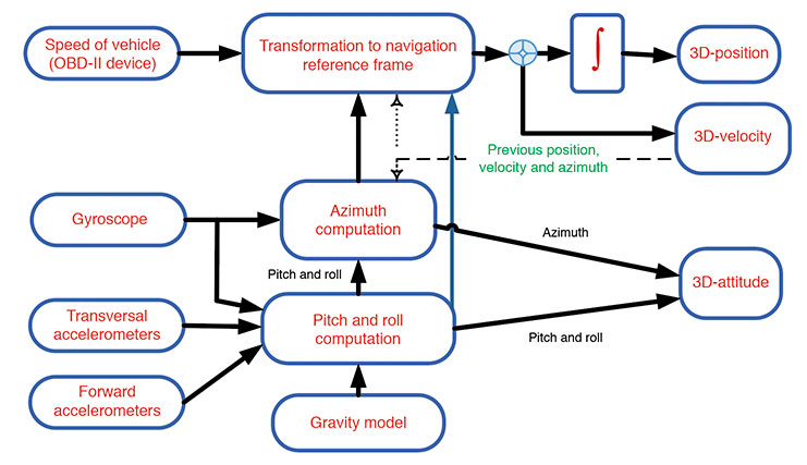
Our approach relies on a RISS incorporating a single-axis gyroscope, accelerometers, and speed measurements. Two accelerometers are used to estimate the pitch and roll angles instead of using two additional gyroscopes. Speed from the OBD-II device and heading information from the gyroscope aligned with the vehicle’s vertical axis enables the calculation of velocity, as shown in FIGURE 1. Calculating pitch and roll from accelerometers rather than gyroscopes retains RISS’s low cost while avoiding the gyroscope’s underpinning integration of velocity and position errors. When pitch and roll are calculated from accelerometers, the first integration of the gyroscope to obtain pitch and roll is eliminated, and thus the error in pitch and roll is not proportional to time integration.
FIGURE 1. Block diagram of speed measurements from the OBD-II device and RISS mechanization. (Image: Authors)
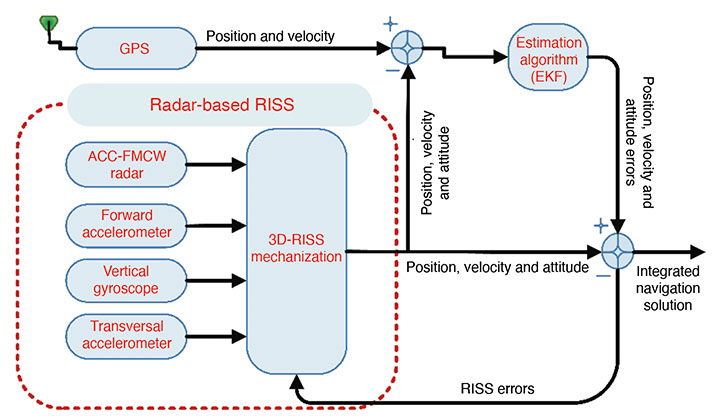
ACC-RADAR-BASED RISS
The radar-based RISS mechanization can provide a complete navigation solution (including 3D position, velocity and attitude) using a reduced number of sensors compared to the classic INS. It consists of longitudinal and transversal accelerometers, one vertical gyroscope and one radar unit (see FIGURE 2). In this mechanization, the OBD-II-device-related measurements are replaced by those extracted from the FMCW radar.
Data fusion is the process of combining data from multiple sensors and related information to achieve more specific inferences than can be achieved by using a single, independent sensor. Fusion processes are often categorized into three modes — low, intermediate and high-level fusion:
Data level combines several sources of the same type of raw preprocessed data to produce a new data set expected to be more informative and useful than the inputs.
Feature level combines features such as edges, lines, corners, textures or positions into a feature map used for the segmentation of images, detection of objects, and so on.
Decision level combines decisions from several expert modes. Methods of decision fusion are voting, fuzzy logic and statistical methods.
Various approaches for multi-sensor data fusion including weighted average, Bayesian estimators, adaptive observers, algebraic functions, fuzzy logic, neural network, soft computing, non-linear system fusion, and Kalman. Drawbacks of these methods include:
the necessity of adding new sensors to the system.
use of linear estimation models that need previous knowledge of signal statistics.
the presence of more than one faulty signal — an essential limitation of the performance.
the need to understand the behavior of the system to generate governing rules.
We used a data-clustering approach, which divides the data from a particular set into subsets (clusters) based on similarity. It could be defined as a reorganizing process for the dataset.
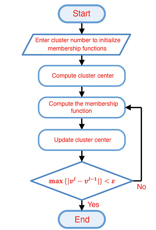
Fuzzy C-means (FCM) Algorithm. The FCM clustering algorithm represents the “fuzzify” step in the fuzzy system and is based on the minimization of an objective function called the C-means functional. The FCM algorithm (FIGURE 3) computes the standard Euclidean distance norm, which induces hyperspherical clusters. Hence it can only detect clusters with the same shape and orientation because the common choice of the norm-inducing matrix is the identity matrix. Three parameters in this algorithm have to be determined at the beginning: the number of clusters, the weighting parameter representing the system’s fuzziness, and the ending threshold, respectively.
FIGURE 3. FCM flowchart. (Image: Authors)
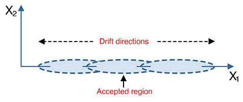
Cluster Number Selection. The FCM algorithm required predefining the number of clusters (Figure 3). This number can be entered randomly, taking iterations and time to converge to the best number, or be calculated. Many methods could be used, such as the validation parameters but only in an offline mode, or by using the data distribution itself and calculating the probability density function (PDF) by first calculating the data’s kernel and then calculating the PDF. This process can be done using the smooth kernel density estimator (SKDE), which is a powerful real-time approach. The main idea is that the measurements values drift in two directions around the acceptable region of measurements (see FIGURE 4). The number of clusters has to be determined in every instance of measurement. From the same figure, the partitions may be three if the drift was in two directions from the accepted region or may be two partitions if the drift at any instance were to the left or to the right direction (one direction drift).
FIGURE 4. Measured data partioning. (Image: Authors)
Subsequently, the number of clusters is determined according to the following two rules, based on the kernel estimator’s maximum peak location: If the maximum peak of the SKDE is left- or right-skewed, then the number of partitions is two; if the maximum peak of the SKDE is centered, then there are three.
METHODOLOGY
The methodology of the implementation of our approach is divided into two parts. The first part utilizes the FCM explained in the previous sections to produce a fused vehicle forward speed from the radar and the OBD-II device. The second part uses the fused speed in the INS mechanization instead of using one sensor only. Further, the mechanization output is integrated with the GPS receiver to establish a more accurate navigation system.
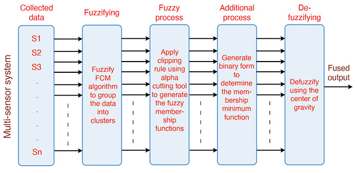
Sensor Fusion using Fuzzy Clustering. The data-fusion technique using the fuzzy clustering algorithm (FIGURE 5) consists of five main parts:
collecting data from the environment by using multiple sensors.
grouping the collected data by using the FCM algorithm in cluster form (“fuzzification”).
applying the fuzzy clipping rule using a cutting tool (fuzzy process).
making use of the clipping-rule properties to perform the fusion mechanism (additional process).
using the mean of the minimum to estimate the fusion output (“de-fuzzification”).
FIGURE 5. Sensor data fusion mechanization. (Image: Authors)
The first part is concerned with setting the sensors for measuring a particular phenomenon from the environment. The second part is to “fuzzify” these measured data, using the FCM to separate the sensors’ data to a certain number of clusters with membership matrix and cluster centers. The fuzzy process deals with the output clusters and membership functions through a fuzzy process called the fuzzy clipping rule. This rule divides the membership function into two regions: the upper region of the cutting threshold, which is clipped and is useless in the fuzzy environment, and the lower region from the cutting threshold, which is the useful region in the fuzzy environment.
Additional processes are applied to benefit from the previous stage — the existence of two regions, one useful, and the other not. This process aims to distinguish between the membership’s functions of the clusters. This could be achieved by generating a binary code that represents the membership function of the clusters. This binary code is generated by comparing the membership function with the threshold value. After the clustering process, each cluster membership function is represented as a binary code. The creation of this code depends upon the membership functions for the clusters and a variable threshold level.
The defuzzification part aims to extract the suitable value and in the same units as those of the measurements. This part produces the fusion output. This output comes from the minimum binary code, which denotes the selected suitable cluster membership function. This cluster contains the optimum solution. This solution or the fusion process output is determined by the centroid of the selected membership function.
Fusion-Radar-RISS/GNSS Integrated Navigation System. In this part of our technique, the fusion algorithm’s output is used in producing a full navigation solution as a control input of the RISS mechanization. This solution is subsequently integrated with the GPS receiver in a loosely coupled scheme using an extended Kalman filter (EKF). The overall proposed integrated navigation system is shown in FIGURE 6.
We carried out the experimental work to verify the proposed navigation system’s effectiveness by traveling real road trajectories. The testbed equipment was mounted inside and outside the test van.
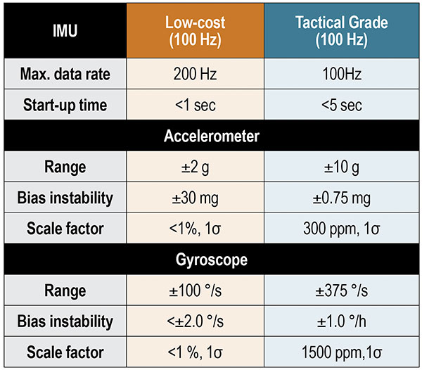
The interior testbed coincides with the van axes. It was rigidly and firmly fixed in the rear seat location using a standard seat chassis. For inertial sensors, we used both a low-cost MEMS IMU and a tactical-grade IMU. The specifications of these units are shown in TABLE 1.
TABLE 1. Performance characteristics of IMUs.
We used a dual-frequency GPS receiver with an output rate of 1 Hz. The tactical-grade IMU includes three fiber-optic gyroscopes and three MEMS accelerometers. The tactical-grade IMU and the GPS receiver were integrated using an off-the-shelf assembly developed by the manufacturer to provide a fully integrated, tightly coupled GNSS/IMU system that delivers a highly accurate 3D navigation solution. This tightly coupled integrated system from the manufacturer is used as a reference to compare the performance and the effectiveness of our proposed methods.
The FMCW radar development kit from the manufacturer was mounted on the front bumper. The unit’s working frequency is 24.5 GHz with a maximum frequency span of 1.5 GHz, a maximum update rate of 10 Hz, a maximum detectable speed of 215 kilometers/hour, and a 3 dB-beamwidth angle of 8.5°. The chirp frequency spans were adjusted to be 0.125 GHz. The maximum coverage range was 30 meters, and the minimum was 0.5 meters.
RESULTS AND DISCUSSION
We conducted a road test with the proposed approach in the downtown area of Kingston, Ontario, Canada, in August 2017.
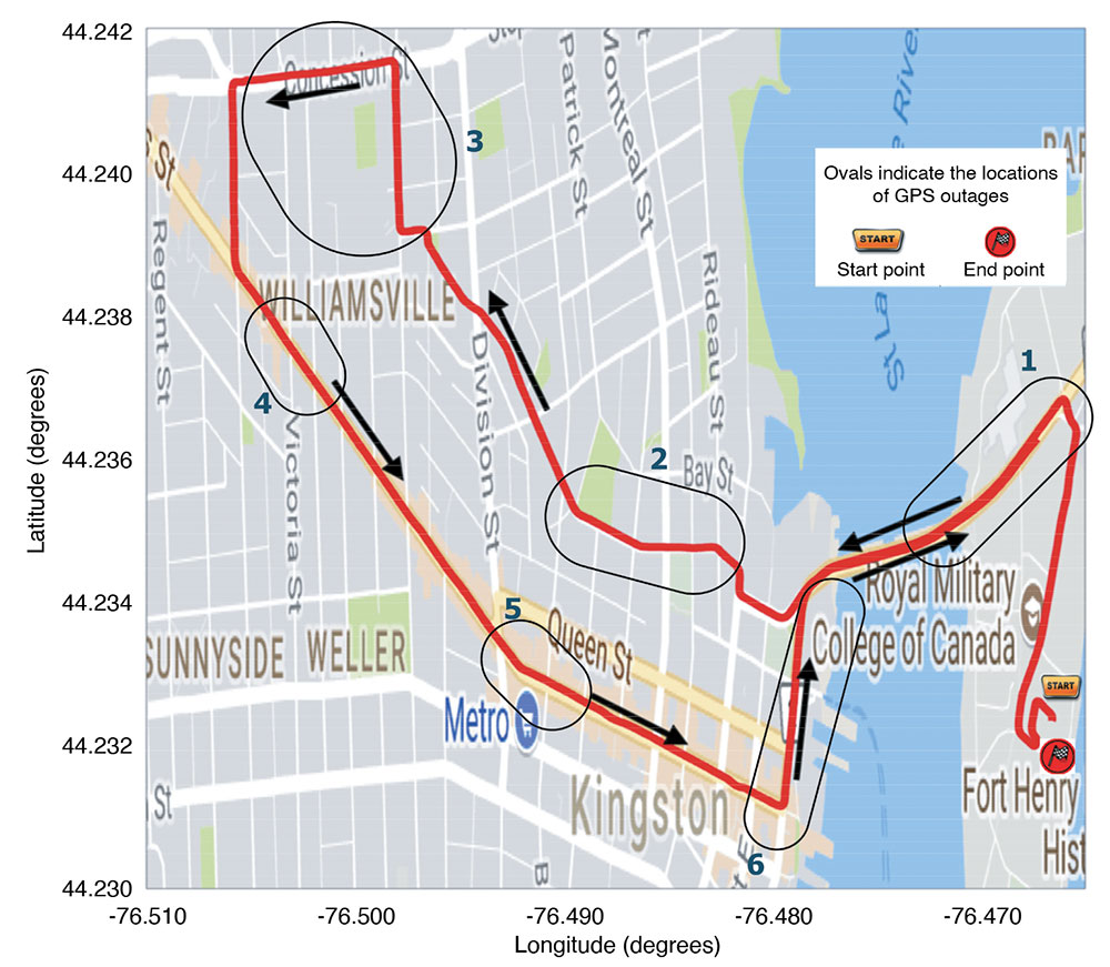
The trajectory followed is shown in FIGURE 7 projected on a Google map with the approximate locations of the outages. The reference is plotted in red, and the black arrows mark the direction of motion.
FIGURE 7. Road test trajectory with ovals indicating the approximate locations of GPS outages. (Image: Author)
Performance Evaluation. The proposed system performance was tested over six simulated outages. The outages have been selected to contain several dynamics such as turns, consecutive turns, stopping, crossing intersections, and straight driving. Furthermore, the outages occurred at different speed levels. The proposed system performance was compared to the traditional RISS/GPS and Radar/RISS/GPS integrated navigation system. The comparison criteria are 2D-position root-mean-square error (RMSE) and the maximum errors.
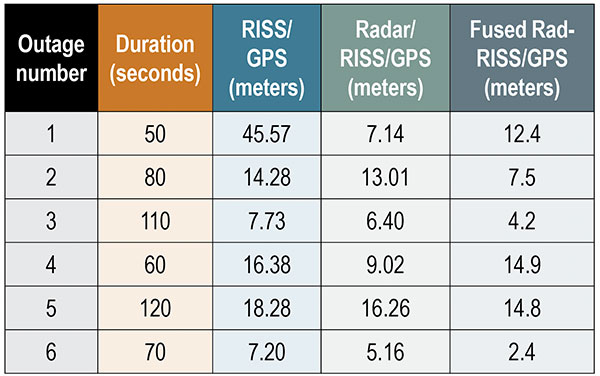
We compared our results using the radar-only versus OBD-II device test. TABLE 2 shows the RMSE of the 2D-position from the three systems in meters. Notice that the proposed system’s performance is better than the other two systems during four of the six outages. This result was achieved using the smart fusion technique to fuse the FMCW radar and the OBD-II speed measurements. Accordingly, the obtained speed is positively affecting the overall system performance.
TABLE 2. 2D-Position RMS-error for the low-cost INS unit during outages.
The average 2D-position RMSE reached 18.24 meters when using the OBD-II speed measurements only and 9.5 meters when using the radar only. On the other hand, the RMSE reached 9.4 meters when using the fusion between the two systems. The improvement percentage was 48.4% when applying the proposed integrated navigation system and 47.8% when using the radar-based system. The results show that the proposed system outperformed the other systems in outages 2, 3, 5 and 6 but did not do better than the radar-based system in outages 1 and 4. We highlight three outages.
The first outage had two left turns after a stop sign over a slippery road. This outage lasted for only 50 seconds, but the system’s behavior was due to wrong measurements combined with a complicated driving scenario when using the traditional RISS/GPS. On the other hand, the radar-based RISS/GPS produces a better solution because of having better velocity measurements in the mechanization, which provides the navigation filter with a better navigation solution. The proposed system limits the drift to around 16.7 meters, while the traditional system had a 68.7-meter drift in its solution.
The proposed system based on the fusion between both speed sensors — OBD-II and radar — could not compete with the radar because of the enormous gap between the two sensors and the lack of extra sensors. Despite that, the system produced a solution with 2D-RMSE of 22 meters, which is also better than the traditional RISS based on the OBD-II device and close to the results from fusing the radar. This problem can be solved by using an extra radar unit, typically installed with an ACC system. The system usually uses six radar units, two in the front and four at the vehicle’s corners.
The second outage duration was 80 seconds and contained two consecutive turns, right then left. The radar-based system reduced the solution drift from 28.13 to 23.58 meters. In contrast to the previous outage, the proposed system reduced the 2D-position maximum error to 14.2 meters. The proposed system’s result is superior to the radar-based system, which performed better in the previous outage because the OBD-II and radar measurements gap is not as large as the previous outage. The dynamics, the average speed and the road surface differ from the first outage.
The third outage was chosen to be a slight turn and mostly straight driving with an average speed of 60 kilometers/hour. This outage lasted for 110 seconds, and the proposed system holds the solution error growth down to 8.9 meters. The traditional system had a higher error growth rate and held it to 20.6 meters, and the radar-based system error reached 14.92 meters. This outage contained fewer dynamics when compared to other outages. Moreover, the slippage and false counting by the OBD-II device was not as considerable as in the first outage.
CONCLUSIONS AND FUTURE WORK
The performance of using a multi-sensor data-fusion technique based on fuzzy clustering successfully fuses the data measured by both the radar and the OBD-II device to produce a more robust forward speed of a moving land vehicle. The proposed system performance tested during six simulated GPS outages containing various dynamics significantly improved the overall navigation system, especially when the GPS signals were blocked. Finally, the fusion between multiple sensors leads to better performance if there are enough sensors or a fault-detection system to prevent the faulty sensor from biasing the fusion results. Moreover, the results demonstrate the superiority of the proposed fused radar RISS/GPS over each system alone.
As an extension to work reported here, we plan to apply our approach with an extra number of sensors to avoid the kind of drift that happened in outage number one. In addition, we suggest that a sensor fault-detection smart algorithm be added to the system to detect and control faulty sensors.
ACKNOWLEDGMENT
This article is based on the paper “Enhanced Land Vehicle Navigation by Fusing Automotive Radar and Speedometer Data” presented at ION GNSS+ 2020 Virtual, the 33rd International Technical Meeting of the Satellite Division of The Institute of Navigation, Sept. 21–25, 2020.
MANUFACTURERS
Our testbed used a Crossbow (now Moog Crossbow, www.moog.com) MEMS-grade XBOW IMU300CC IMU and a NovAtel/Hexagon (www.novatel.com) IMU-CPT tactical-grade IMU. We also used a SPAN-OEM4 or SPAN-SE NovAtel/Hexagon dual-frequency GNSS receiver. The radar development kit used is a Sivers IMA (now Sivers Semiconductors, sivers-semiconductors.com) RK1001K/00.
ASHRAF ABOSEKEEN is a lecturer in the Department of Avionics Engineering, Military Technical College, Cairo, Egypt. He received a B.Sc. and M.Sc. in electrical engineering from the Military Technical College in 2004 and 2012, respectively. He received his Ph.D. from the Department of Electrical and Computer Engineering, Queen’s University, Kingston, Ontario, Canada, in 2018.
UMAR IQBAL is an assistant clinical professor in the Department of Electrical and Computer Engineering, Mississippi State University. He completed his Ph.D. in electrical and computer engineering at Queen’s University in 2012.
ABOELMAGB NORELDIN is a professor in the Department of Electrical and Computer Engineering, Royal Military College of Canada, Kingston, Ontario with a cross-appointment at both the School of Computing and the Department of Electrical and Computer Engineering, Queen’s University.
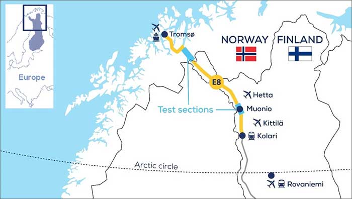
An ESA-supported project is testing autonomous vehicles on an intelligent road in Lapland, Finland.
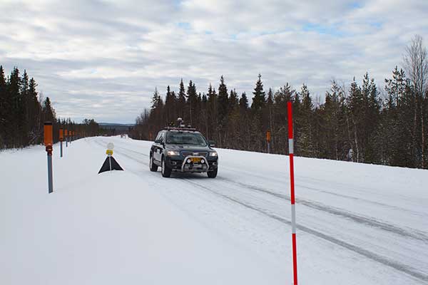
Known as Snowbox, this 10-km stretch of forest-lined roadway on Finland’s E8 highway has been specially equipped for autonomous driving tests, ESA said. Containing cameras, “laser radar” lidar, ultra-wideband antennas and reflective panels, the road itself is underpinned by power and fibre optic lines, and embedded with pressure sensors to record road surface conditions and the speed and type of vehicles driving along it.
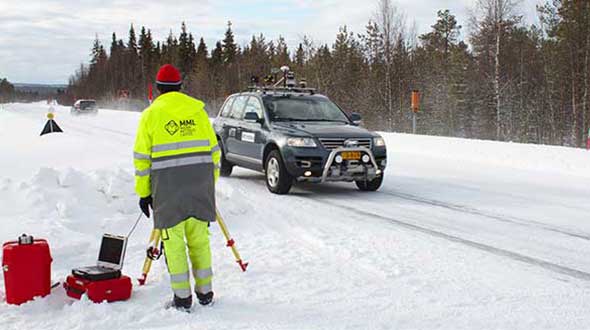
Known as Snowbox, this 10-km stretch of forest-lined roadway on Finland’s E8 highway has been specially equipped for autonomous driving tests, including FinnRef GNSS reference stations, as seen here. (Photo: ESA)
“If autonomous vehicles can drive well here, they can drive almost anywhere,” said Sarang Thombre of the Finnish Geospatial Research Institute, who’s managing the Arctic-PNT project. “Our project aimed at ensuring in particular that the precise positioning required by autonomous systems was available here, to establish this test site is indeed somewhere that driverless vehicle manufacturers should employ for testing. We carried out experiments with a robotic car over two successive seasons to show that the necessary precise positioning, down to 20 cm, is indeed accessible.”
Snowbox is also linked to the FinnRef network of satellite navigation reference stations, to deliver corrections for precise satnav positioning. By performing positioning measurements continuously at fixed locations, these reference stations serve as a standard, allowing the identification of measurement errors to boost positioning accuracy on a localized basis, ESA added.
Snowbox map. (Photo: ESA)
“The Arctic is a difficult environment for autonomous driving in general,” Thombre said. “Signal disturbance due to the ionosphere, the electrically charged layer of the atmosphere, degrade satellite navigation performance. This effect is more pronounced in the Arctic region. And satnav augmentation systems also face challenges.
“Because their signals are broadcast from geostationary satellites, they are only viewable here at an elevation of up to 10 degrees above the horizon. And mobile coverage — useful for providing correction data from reference networks — is also inconsistent.
“In addition, possibility of mists and fog, snowstorms and rainfall make it difficult for cameras and lidar, while ice and snow on the road means wheel speed sensors may slip. And temperatures that can plunge down to below -30°C can impede the performance of electronics.”
The Arctic-PNT team’s testing was based around a robotic car crammed with sensors and recording equipment. Called Martti, the vehicle was supplied by Finland’s VTT Technical Research Centre.
Snowbox test roadway. (Photo: ESA)
“While Martti is capable of autonomous driving, we drove it manually,” Thombre said. “We were using it to capture all the data we needed. We started off using solely satellite navigation – including Europe’s Galileo and EGNOS – progressively adding more and more augmentation data, including in-car sensors, and corrections from the FinnRef stations, to reach the all-important precise positioning threshold of 20 cm.
“To access the FinnRef corrections from the car systems we tested out various mobile sim cards. Adding to the challenge, we crossed an international border, because part of the E8 highway is instrumented on the Norwegian side as well — called Borealis.”
The Snowbox infrastructure was established along the E8 because, while it is a remote roadway it is also economically important, with trucks heading south from Arctic fisheries.
The Arctic-PNT test campaigns, starting from 2018, gave a positive bill of health to the Snowbox, which is available for experiment campaigns. The campaigns were supported through ESA’s strategic initiatives for the Arctic region.
Feature image: The Arctic-PNT team’s testing was based around a robotic car crammed with sensors and recording equipment. Called Martti, the vehicle was supplied by Finland’s VTT Technical Research Centre. (Photo: ESA)