SkyTraq Technology Inc., a fabless GNSS positioning technology company, has introduced the S1722DR8 GNSS dead-reckoning receiver, integrating a 3-axis gyroscope/accelerometer and barometric pressure sensor with a GNSS receiver.
Using wheel/speed data from vehicle to perform sensor-fused solution, S1722DR8 achieves 100-percent coverage. It is designed for vehicles applications requiring high performance and reliable uninterrupted positioning.
The S1722DR8 can be flexibly mounted in any orientation, and does not have to be placed horizontally as in conventional dead-reckoning solutions using single-axis gyroscope. The auto-calibration feature of S1722DR8 greatly simplifies installation procedure; the short calibration time upon first use also improves user experience.
The S1722DR8 GNSS dead-reckoning receiver, compared to a U.S. penny.
The on-board barometric pressure sensor provides highly accuracy altitude information, useful for differentiating floor levels of multi-story parking garages or stacked highways.
The S1722DR8 is compact, measuring 17 x 22 millimeters. It offers continuous navigation even in GPS-signal-denied environments such as tunnels or underground parking lot. Augmented by gyroscope and accelerometer sensor data, it is also designed for vehicle insurance accident-reconstruction applications.
An S1722DR8 engineering sample, evaluation kit and datasheet are available now. Volume delivery to customers begins in June. The S1722DR8 is manufactured in ISO/TS 16949 automotive-certified factory.
Like thousands of water utilities across the U.S., the City of Sebring, Fla., Utilities Department is tasked with providing a safe and reliable water supply, while managing all the dispersed assets of the water distribution and wastewater systems. This means regularly locating, mapping and inspecting assets to maintain service levels and operations.
This City of Sebring storm drain runs down the center of a street. (Photo: TerraGo)
When Sebring evaluated this approach, the city received a quote for geographic information system (GIS) software that was more than $30,000 and bids for surveying services that were as high as $300,000, which didn’t include the mobile tools to collect the data or integration with the existing CAD system.
“We could see the traditional GIS and GPS approach was going to eat us alive cost-wise,” said Mark Kretz, water plant operations, Sebring Utilities.
Sebring Utilities then researched mobile products to see if other organizations had field success using iPads and iPhones to do the work. Sebring still needed to achieve survey-grade accuracy — sub-meter, centimeter-level in some cases. This is impossible with an iPhone or iPad out of the box, which delivers 5 meters at best.
Installation of a storm drain in Sebring. (Photo: TerraGo)
Some tasks, such as mapping an underground valve, need sub-foot or better accuracy. Other tasks, such as locating an aboveground valve, could be seen within 3 to 5 meters, so just the iPad would work.
Mark Kretz, Water Plant Operations, City of Sebring, conducts water asset inspections and maintenance. (Photo: City of Sebring)
CAD integration. Sebring also needed to be able to utilize computer-aided design (CAD) diagrams on its mobile devices to identify and locate valves and other assets in the field. In the past, the utility relied on printed CAD drawings, a cumbersome and costly solution. Plus, with time of the essence when containing a leak, workers wanted on-demand access on their mobile devices.
With the multitude of assets from fire hydrants to valves to sewers, the data collection and maintenance work varied greatly. Sebring needed a way to create custom forms and workflow processes, and be able to modify them over time or create new ones when needed.
In the end, the city opted to deploy TerraGo Edge on iPads. With TerraGo Edge, Sebring was able to integrate with GPS receivers that pair to iPads or iPhones via Bluetooth because the product is fully integrated at the software level with Apple-certified GPS receivers. This enabled the city to cut costs, bring surveys in-house and improve response times for repairs. TerraGo Edge also delivers custom forms, CAD diagrams and survey-grade accuracy.
“On a day-to-day basis, the biggest benefit is that we get the ease of use of an iPad, and didn’t have to buy and use proprietary GPS handhelds, which are more complex and vastly more expensive,” Kretz said.
CAD on iPhone with TerraGo Edge. (Image: TerraGo)
Edge benefits
Cost savings of 90 percent over traditional GIS and GPS systems
Trimble has added a new scalable GNSS receiver to its geospatial portfolio. The Trimble R9s GNSS receiver is scalable and flexible. Built on a sleek, modular GNSS platform, geospatial professionals can add functionality according to their workflow demands, such as being deployed as an RTK base station or an RTK rover mounted on a rod, in a backpack or on a vehicle.
The Trimble R9s GNSS receiver provides access to multiple GNSS constellations, wide-band 450 MHz internal radio, Ethernet connectivity and is easily configurable via the front panel. The solution also offers scalability from an entry-level receiver for post-processing, to a full-featured triple-frequency GNSS base and rover.
The R9s also supports corrections services, including Trimble CenterPoint RTX (better than 4 centimeters delivered via L-band satellite) and enhanced xFill technology, which allows surveyors to continue collecting data with centimeter-level accuracy indefinitely when RTK or VRS connectivity is lost.
Options such as Trimble Access field software, Trimble DL Android app and Web user interface or front panel allow the receiver to be configured for optimal performance to support a broad range of survey workflows.
An Australian company that manufacturers GNSS echo sounders aided the aiders — leading a medical ship through uncharted waters in Papua New Guinea.
The CEESCOPE echo sounder enabled the ship to reach volunteers who were working to save the life of a newborn.
The ship, operated by YWAM Medical Ships Australia (YWAM MSA), visits remote villages in Papua New Guinea, giving communities access to life-saving medical and dental services. The village locations are accessed by river, and while often there is adequate tide information to help navigate, there are no available charts or bathymetry data for the passages upriver.
Without a navigable route to follow, the medical ships simply could not travel to locations where help is needed the most.
To solve this problem, YWAM decided to make its own charts, with help from CEE HydroSystems. Using a small, fast launch equipped with a CEESCOPE single-beam echo sounder and GPS hydrographic survey system, YWAM volunteer and master mariner Jeremy Schierer set out to find safe routes through vast river deltas ahead of the medical ship.
While surveying at high speed to maximize the area covered, Schierer executed reconnaissance patterns along the river while continuously updating the hydrographic survey plan based on the results seen.
Survey data gathered and processed in HYPACK acquisition software were exported to the navigation system of the ship to provide waypoints marking the safe passage route along the river. Used with available and observed tide data, the navigator of the vessel could confidently travel upriver without the risk of grounding.
The CEESCOPE is a one-box survey system that can be swapped between the two available 4.2-meter and 5.2-meter boats. It can be used without an acquisition PC on the survey launch if needed — all data recorded on the internal memory, and can run on its own battery power for an extended duration. With operation in remote areas on small boats, reliability and usability were key for YWAM.
YWAM also used the CEESCOPE with HYPACK from the wheelhouse to navigate the ship along the surveyed routes on custom electronic charts.
In the third year of YWAM’s operation in Papua New Guinea, Schierer recorded a staggering 3,400 kilometers (2,000 miles) of bathymetry to help navigate the Pacific Link. All of the rivers were uncharted before the ship traveled upstream. With incomplete tide-station coverage, determining the ship’s path was a complex calculation. Despite this, and complicated by a bore tide, YWAM was able to take its vessel 75 kilometers upstream in the Bamu River, Western Province, without published charts.
However, the most startling example of the benefit of the YWAM hydrographic survey approach took place in the second year of operation.
“Baimuru is up the Pie River from Port Romilly in the Gulf Province,” Schierer said. “The only previous known route took us about four hours through the rivers and required high tide and daylight.
“We went out with the CEESCOPE to see if we could find an alternate and more direct route to the open sea. We left the ship just before sunrise and went as far as 8 nautical miles off the coast to confirm a good passage — and we found one that was deep enough.”
Instead of leaving when scheduled, the ship received an emergency call from the medical center about 300 meters away on the shore, where there is no electricity or running water.
“A lady had just given birth, and they were requesting attendance by our doctor and midwife. Evidently the baby was born in the canoe on the way to the medical center, and for some time the baby lay in the bottom of the canoe.
“By the time we unsecured our small boat and got the medical team ashore, the baby was 35 degrees Celsius and not warming up. Our medical team was able to assist in warming the baby and reported that if we had not been there, they were quite certain that the baby would not have survived the night.
“The only reason we were still there was because we had the CEESCOPE and had been able to find another route. We’ve charted more than 1,200 kilometers with the CEESCOPE so far, and it is making a huge difference,” Schierer said.
The track of the medical ship on the previously uncharted Bamu River.
Based in Sydney, CEE HydroSystems opened an office in San Diego, California, in late 2015, to serve the United States and Canada. The company specializes in RTK GNSS-enabled precision shallow water hydrographic echo sounders. Its products are aimed at surveyors conducting shallow water bathymetric surveys.
“For inshore hydrographic surveys of water bodies such as canals, lakes, rivers or industrial water impoundments, survey firms inexperienced in hydrographic methods often have to resort to conventional and laborious processes using sounding lines, range poles or basic sonar equipment,” said Peter Garforth, CEE HydroSystems managing director. “Our CEESCOPETM survey system puts a RTK GNSS solution and precision echo sounder into a compact single package, allowing surveyors to vastly improve productivity on these surveys.”
The CEE range of echo sounders with GPS was first developed to offer surveyors a one-box solution to reduce hardware setup time and the need for interconnecting components.
Portable echo sounder
The CEESCOPE uses a built-in RTK GNSS receiver and UHF radio modem to acquire RTK-quality position and elevation that is used in hydrographic surveying software to output xyz point-cloud data files of bottom elevations in local coordinates and datums. In RTK mode, the CEESCOPE can be directly connected to the local UHF base station radio. The internal CEESCOPE GNSS receiver provides accurate position data at 1–20 Hz, and the single-beam echo sounder records soundings at up to 20Hz.
Both data streams — plus any ancillary measurements fed into the unit such as heave, pitch and roll — are precisely time-tagged using a 1PPS signal and then recorded on the CEESCOPE internal memory. Simultaneously, the data are output to an acquisition PC or tablet.
u-blox has released new firmware, FW 3.01, for its u-blox M8 concurrent multi-GNSS platform.
u-blox M8 FW 3.01 now also supports Galileo, in addition to GPS, GLONASS, BeiDou, QZSS and SBAS. It can track up to three constellations concurrently and makes use of all SBAS and QZSS augmentation systems at the same time.
With Galileo fully deployed, the European positioning system will provide access to 24 additional satellites, significantly increasing availability of GNSS signals and further improving position accuracy in challenging urban environments. u-blox M8 supports Galileo-based eCall, the European emergency call system, which will be required in new vehicles starting 2018. u-blox M8 is also compliant with ERA-GLONASS, eCall’s Russian equivalent.
In addition, with FW 3.01, u-blox M8 now boosts the BeiDou acquisition sensitivity and adds support to the Indian GAGAN augmentation system.
u-blox M8 chips and modules are able to operate reliably in difficult environmental conditions as well as in a security attack scenario. Because a growing number of wireless systems rely on GNSS positioning, the threat of attacks, such as diversion of drones or hijacking of car electronics, has become very real.
Security mechanisms are now embedded in FW 3.01, the result of years of intense research at u-blox R&D labs. An anti-spoofing feature detects fake GNSS signals, and a message integrity protection system prevents “man-in-the-middle” attacks. Yet another security function detects and suppresses jamming. Since all this functionality is already built into u-blox M8 FW 3.01, these security mechanisms are a lot more effective than an external system implementation.
Automotive-grade u-blox M8 products benefit from an extended operating temperature of -40 to +105°C and are AEC-Q100 Grade 2 qualified. The extended temperature range allows more flexibility in vehicle integration, such as by integrating a u-blox M8 GNSS receiver into a roof-top antenna where temperatures can reach 105°C.
Another feature of FW 3.01 is the 10 percent power reduction compared to earlier firmware versions of u-blox M8.
The u-blox M8 platform supports applications where navigation performance, reliability, and high accuracy are paramount, whereas the recently announced u-blox 8 platform addresses power sensitive applications such as wearables. u-blox M8 and u-blox 8 products are pin- and software compatible.
Firmware to upgrade existing flash-ROM based u-blox M8 products can be downloaded from the u-blox website. Products with FW 3.01 in ROM will become available in Q2′ 2016.
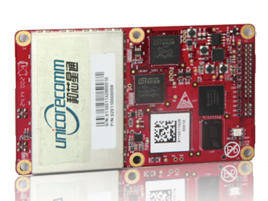
The UB380 GPS/GLN/BDS tri-constellation octa-frequency high-precision board.
High-end GNSS board
For high-precision positioning, navigation and GBAS applications
The UB380 multi-GNSS receiver has 384 channels, based on Unicore’s multi-GNSS system on a chip. It features Unicore’s latest real-time kinematic (RTK) engine, which can process triple-frequency BDS and GPS and dual-frequency GLONASS observation data. This can significantly reduce initialization time, improve position accuracy and enhance reliability in difficult environments such as city canyon and canopy, as well as make the long baseline RTK possible. The receiver board can support GPS L1, L2 and L5; GLONASS L1, L2; and BDS B1, B2 and B3. The support of GPS L2P and L2C can satisfy the high-precision requirements of GBAS reference station equipment. The UB380 is compatible with industry-standard GNSS boards in size, interfaces and electrical standards.
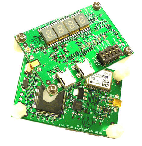
M12M Replacement Receiver GNSS module. Photo: Jackson Labs Technologies
Legacy receiver module
Plug-and-play upgrade for xli server, fury GPSDO
The M12M Replacement Receiver released is form, fit and function compatible to the legacy Motorola M12M and M12+ timing and navigation receivers. It uses an eighth-generation GNSS timing-enabled receiver, allowing 72 GNSS-channel reception with any two GNSS systems being received simultaneously. It adds configurability via USB ports and dual in-line package (DIP) switches and various status displays. GPS, GLONASS, BeiDou, QZSS and SBAS signals can be received. The module supports NMEA, Motorola binary and u-blox binary as well as SCPI (GPIB) communication protocols; is designed to allow plug-and-play retrofit of equipment designed for legacy Motorola receivers; and is certified as a plug-and-play upgrade to the Symmetricom/Microsemi XLI server and the Jackson Labs Technologies Fury GPSDO. It can be used to retrofit products for GLONASS/BeiDou compatibility. The module enhances performance parameters such as time to first fix; position, velocity and timing accuracy; tracking sensitivity; the addition of SBAS (differential compensation) capability; and the addition of external interfaces such as USB and a synthesized frequency output.
High-gain, high-rejection family designed for cell and telecom
The TW3150/52 antennas feature a 50-dB low-noise amplifier (LNA) gain to handle long cable runs often associated with installation on telecommunications towers. They cover the GPS L1 and SBAS (WAAS, EGNOS and MSAS) frequency bands and provide excellent cross-polarization rejection and enhanced multipath rejection.The TW3150 antenna features a four-stage dual-filtered LNA, while the TW3152 antenna includes an additional SAW pre-filter. This provides better than 80-dB of signal rejection above 1610 MHz and below 1545 MHz. The antennas are IP67 and MIL-STD-801F Section 509.4 compliant to withstand challenging environmental conditions.
Provides support for GPS, GLONASS and BeiDou with MediaTek
The ORG1510-MK Multi Micro Hornet is a fully integrated multi-GNSS (GPS, GLONASS and BeiDou) module. The miniature low-power architecture is designed to provide a GNSS component to devices that require fully featured components with small footprints, such as UAVs designed to follow action sports and other fast-moving activities or wearables. The ORG1510-MK contains the MediaTek MT3333 chip, which supports a fast update position calculation rate, and contains an onboard flash memory that does not erase when power is off. It consumes little power with the use of both standby mode and backup mode, and, in advanced applications, a periodic mode that can turn the device on and off when in backup or standby.
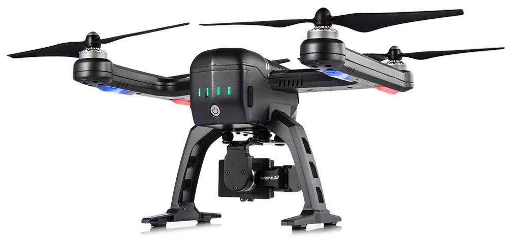
Designed for recording sports activities, the FLYPRO XEagle UAV has replaced traditional UAV remote controllers with the XWatch, a smartwatch designed to control the XEagle. Users can control the devices to take off, land and follow, as well as adjust flight height with one click on the wrist within 300 meters. The smartwatch design enables users to fly the aerial vehicles to take high-definition pictures and videos while engaging in intense sports. A voice-control feature allows users to fly the XEagle without moving their hands using commands such as “FLYPRO, take off” and “FLYPRO, follow me”.
Thermal imaging camera core designed for integration
FLIR Tau 2 thermal imaging cameras are suited for demanding applications like UAVs, thermal weapon sights and handheld imagers. Improved electronics now give Tau 2 even more capabilities, including radiometry, increased sensitivity (<30 mK), 640/60 Hz frame rates, and powerful image processing modes that dramatically improve detail and contrast. Since the electrical functions are common between the Tau 2 640, 336 and 324, integrators have direct compatibility between the different camera formats, and Tau camera versions share many of the same lens options.
Amazon’s latest version is designed to deliver packages in 30 minutes
Source: Amazon
A new drone design introduced by Amazon for its planned Prime Air Delivery service is larger than the previous quadcopter and has a more advanced design, including the ability to operate with an auto-loading system that sets the payload inside an internal carrier bay. The hybrid design combines vertical lift and horizontal flight capabilities using lift fans and a pusher prop. The drone is capable of flying at an altitude of about 400 feet (122 meters) at about 55 mph (88 km/h) for a range of 15 miles (24 kilometers). It has sense-and-avoid situational awareness technology and is designed to deliver small packages in under 30 minutes.
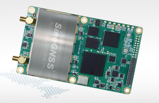
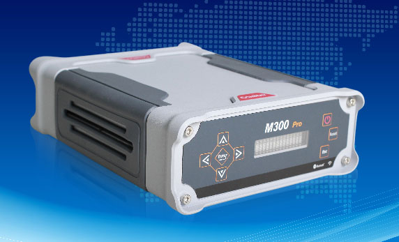
The M300 Pro is a multi-purpose CORS GNSS receiver designed for applications such as positioning infrastructure, active geodetic network, deformation monitoring, machine guidance, harbor construction, land surveying and marine surveying. Designed for reference stations, the M300 Pro tracks GPS, GLONASS and BeiDou (B1, B2, B3), and will track Galileo, QZSS and other coming constellations. Its web server function enables remote control for access, configuration, programming, data download, reboot/restart, firmware update and code registration. It is compatible with many kinds of CORS software, using the standard data format RTCM and the various data transfer protocols such as UDP, TCP and NTRIP. Raw GNSS observation data can be saved in RINEX format and remotely downloaded. Multiple ports can be configured and connected with external sensors such as meteorological sensors, barographs and inclinometers. The PPS output function provides a guarantee for precision timing. It also has the functionality of event mark and external memory.
The Leica Velocity and Displacement Autonomous Solution Engine (VADASE) detects fast movements of man-made and natural structures in real time, running on board Leica reference stations and monitoring receivers. VADASE provides an in-depth look at accurate, high-rate velocity and displacement information of various activities and structures. It gives engineers and researchers complete, precise and reliable monitoring information. VADASE delivers actionable information independent of any GNSS real-time kinematic (RTK) correction service.
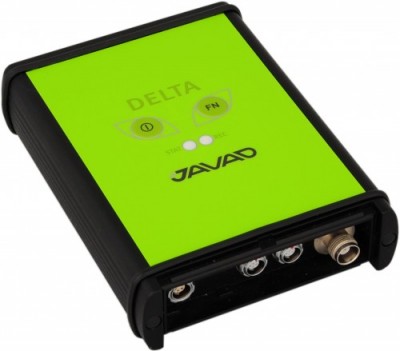
GNSS receiver with onboard memory for data storage
The DELTA-3 receiver has 864 GNSS channels, along with three powerful processors and program memory in a single chip, which uses less power and makes the total system less expensive. The 864 channels allow tracking of all current and future satellite signals. Delta-3 can track and decode the QZSS LEX signal messages. It is a powerful and reliable receiver for high-precision navigation systems, including high-dynamic systems, for machine and traffic control, high-precision surveying, and geodynamics and aerogeophysics applications. Delta-3 can operate as a receiver for post-processing, as a Continuously Operating Reference Station (CORS), or as a portable base station for real-time kinematic (RTK) applications, and as a scientific station collecting information for special studies such as ionosphere monitoring.
A configuration of ArcGIS and a JavaScript application
Photo Survey is designed for local governments to publish street-level photo collections and conduct focused property surveys that can identify blight, damaged structures or construction activity. It leverages location-enabled photos produced by many commercially available cameras and simplifies data processing so street-level photo collections can be gathered on a regular basis. Photo collections can then be combined with relevant survey questions in an ArcGIS Online map, and shared with the Photo Survey application. Once complete, the Photo Survey application can be used by the general public or local government staff to review street-level photos and complete property surveys.
Advances in micro-electro-mechanical systems (MEMS) sensor technology include temperature-sensing MEMS oscillators (TSMO). Pairing a TSMO with a GNSS receiver, the authors successfully performed carrier-phase positioning and obtained accuracies better than typically required for automotive applications. MEMS oscillators can present space and cost advantages in integrated circuit assembly. By Bernhard M. Aumayer and Mark G. Petovello
MEMS oscillators have found their way into the electronics industry and are on their way to enter a multi-billion consumer devices market, which is currently dominated by crystal-based oscillators. One technology review concluded that MEMS oscillators fill the gap between high-performance quartz and low-performance LC (inductor+capacitor) oscillators while allowing for better system and package integration.
Nevertheless, due to stringent requirements on frequency accuracy and phase noise, MEMS oscillators have not yet been integrated in GNSS receivers.
In earlier research, we demonstrated the feasibility of using a temperature-sensing MEMS oscillator (TSMO) in a software receiver, operated over the full industrial temperature range (–40° to +85° C) for pseudorange (code) positioning. However, high-accuracy carrier-phase positioning techniques require uninterrupted carrier-phase tracking, producing more challenging requirements for the receiver’s oscillator.
Here, we extend that research to demonstrate the feasibility of using a TSMO for carrier-phase positioning.
Background
The MEMS resonator used here has an approximately 150 ppm frequency drift over the temperature range of –40° to +85° C, which is about three to five times greater compared to a standard crystal. The integrated temperature sensor provides very good thermal coupling with the resonator, enabling accurate frequency estimation once the frequency versus temperature function (FT polynomial) is estimated.
This FT polynomial can be estimated by periodically measuring the frequency and temperature at different temperatures, and fitting the FT polynomial to the measurements. After this calibration stage, the oscillator frequency error can be estimated using the temperature measurement and the polynomial only. This frequency error can aid the GNSS receiver for acquiring and tracking signals.
As the temperature measurements are affected by noise — which is also amplified by the FT polynomial, producing frequency noise in the receiver — the temperature measurements can be filtered accordingly to reduce noise.
Methodology
Temperature compensation of the oscillator frequency can be beneficial in scenarios with fast changes in temperature (and therefore fast changes in frequency) or when operating the oscillator at extreme temperatures, where temperature sensitivity is more pronounced. The TSMO implements an onchip integrated temperature sensor in close proximity to the resonator and provides an accurate estimate of its temperature. We first examine more complex and non-real-time capable filters to assess performance improvement and limits of bandwidth reduction.
For the second part of this research, where the TSMO based GNSS receiver’s measurements are used for RTK positioning, none of the conditions requiring temperature compensation (fast changes or extreme temperatures) are met, and therefore temperature compensation was not applied.
Temperature Measurements Filtering. When temperature compensation is applied, filtering of the chip-integrated temperature sensor measurements is performed to reduce measurement noise introduced by the temperature measurement circuit. As the signal frequency and phase from the satellite can — under negligible ionospheric scintillation conditions — be assumed significantly more accurate and stable than the local oscillator’s carrier replica, common errors in the received signals’ carrier frequencies can predominantly be accredited to the local oscillator.
Therefore, under the condition of a defined tracking loop, estimated frequency accuracy and phase tracking stability are suitable measures of the local oscillator’s short-term frequency and phase stability, as well as the influence of the temperature compensation.
The temperature compensation method is being digitally applied to the digitized IF signal as a first stage in the software receiver (Figure 1). For generating this signal, a filtered version of the raw temperature measurements is generated and a function (temperature compensation or FT polynomial) to convert those temperature measurements to local oscillator frequency estimates is applied.
Figure 1. Temperature compensation and signal processing structure.
The digitized IF samples of the received signal as well as the frequency estimates from the temperature measurements are then processed by the GSNRx software GNSS receiver developed at the University of Calgary. Satellite-specific phase-lock indicators (PLI) as well as the receiver’s clock-drift estimates are extracted and analyzed, and compared to the results from other filter implementations.
The temperature filters are designed as a combination of variable length finite impulse response (FIR) filters and 1-tap inifinite impulse response (IIR) filters, as this design yields a reasonable trade-off between high stop-band attenuation, small group delay, low complexity and high filter stability. Although feasible in hardware implementations, multi-rate filtering approaches were not investigated.
The filters used are summarized in Table 1, where filters #1 and #2 were used in our previous research. In the table, BC denotes a box-car FIR filter implementation, and BW refers to an approximated brick-wall filter (truncated sinc in time domain). Although the order of the filter is higher, all feedback coefficients (an) other than the first a1 are zero for stability reasons. The stated bandwidth is the 3 dB bandwidth of the filter, (fwd/bwd) indicates forward and backward filtering, and GDC indicates group delay compensation.
Table 1. Filter implementations for temperature measurements.
Carrier-phase positioning. It is well known that carrier-phase measurements can deliver much higher accuracy positions than pseudorange measurements. The challenge for MEMS oscillators is to mitigate the phase noise of the resonator, and any noise resulting from temperature compensation, to allow continuous phase tracking. Failure to do this will result in more cycle slips, which in turn will limit the benefits of using carrier-phase measurements (since the navigation filter will have to more frequently re-estimate the carrier-phase ambiguities).
Testing
The static data set collected in our earlier research was reused for this work. The data was collected from a static rooftop antenna, while the TSMO was placed inside a temperature chamber, which was performing a temperature cycle from +85° to –30° C and back up to +60° C. The temperature compensation polynomial (Figure 1) was fit using the clock drift estimate from running the software receiver with the same data set without any temperature compensation. The temperature filters in Table 1 were then applied to the raw temperature measurements, and processed with the same software receiver as in our earlier work, allowing for direct comparison of the results.
Carrier-phase positioning. To mitigate effects from orbit and atmospheric errors, first a zero-baseline test was carried out on a rooftop antenna on the CCIT building at the University of Calgary. Two identical IF sampling front-ends with a sampling rate of 10 MHz were used for each of the tests, one utilizing a built-in TCXO and the other using the external MEMS oscillator clock signal. A commercial GNSS receiver was used as a static base for this setup. The TSMO and TCXO based front-ends were used as a rover, all connected to the same antenna. For all tests, only GPS L1 C/A signals were used by the devices under test.
Second, a short-baseline test utilizing two antennas about 2.5 m apart was carried out, with the same equipment. For reference, surveyed coordinates of the antennas’ base mounts were used. For these two tests, the front-ends and oscillators were at constant temperature (to within variation of room temperature) on a desk.
Third, two road tests in a car driving around Springbank airport close to Calgary were performed. One test involved smooth driving only, and the second test was performed by rough driving over uneven roads so that higher accelerations on the oscillators were provoked. To allow a performance comparison between the TCXO and TSMO based receivers, the two front-ends were used as rover receivers at the same time and were connected to the same geodetic-grade antenna mounted on the vehicle’s roof.
Equipment and processing. All samples from the IF-sampling front-ends were processed with the University of Calgary’s GSNRx software GNSS receiver to obtain code and carrier phase as well as Doppler measurements. These measurements were subsequently processed with the University of Calgary’s PLANSoft GNSS differential real-time kinematic (RTK) software to obtain a carrier-phase navigation solution.
As a reference, a commercial GNSS/INS system using a tactical-grade IMU was used. The dual-frequency, multi-GNSS, carrier-phase post-processing of the reference data provided a reference position of better than 1 cm estimated standard deviation in all three axes, which is in the following referred to as “truth.”
The kinematic tests were carried out with the PLAN group’s test vehicle, a GMC Acadia SUV-style vehicle. A geodetic-grade antenna was mounted in close vicinity to the LCI tactical-grade IMU as shown in Figure 2. The antenna was split to a reference receiver and the two IF-sampling front-ends. The front-ends were rigidly mounted to each other as well as to the TSMO board to ensure similar accelerations on both oscillators. The front-ends were placed in the center of the passenger cabin.
Figure 2. Equipment setup on PLAN group’s test vehicle.
The kinematic tests were performed near the Springbank airport close to Calgary, Alberta. For a base station, a commercial dual-frequency receiver was set up on an Alberta Survey Control Marker with surveyed coordinates. A leveled antenna was used with this receiver, and 20 Hz GPS and GLONASS raw measurements were collected to provide a base for both the reference receiver and the receivers under test.
Results
First, we compared results from improved temperature filtering to results from our earlier work. The performance of temperature measurement filtering is quantified with regard to frequency accuracy (mainly arising from filter group delay) and phase-lock indicator values of the tracked signals, which are mainly deteriorated from noise introduced by temperature compensation.
The best performance with regard to PLI (Figure 3) was achieved using the forward-backward 1-tap IIR filter (#4 in Table 1).
Figure 3. Cumulative histogram of PLI with temperature compensation.
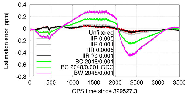
While the estimation error introduced by this low-bandwidth and high group delay filter was significant especially at fast temperature changes before and after the temperature turnaround point at 2067 s into the run (Figures 4 and 5), the forward-backward filtering cancels a major part of that delay. Note that this filter has even lower bandwidth (Table 1) than the same filter used in forward-only filtering, as the resulting magnitude response squares with the forward-backward filtering approach.
Figure 4. Temperature-based estimation of oscillator error.Figure 5. Error in temperature-based estimation of oscillator error (note the larger error due to filter delay).
Only a slight performance decrease can be seen when using a boxcar filter with 2048 taps, but only when compensating for the FIR part’s known group delay of approximately 1 s. It is noted that filters #4 and #6 — which show best performance — are only usable in post-processing or with significant latency.
In contrast to group-delay compensated filters, which might not be applicable in low-latency, real-time applications, the even lower bandwidth 1-tap IIR filter — although introducing a still significant group delay — resulted in best tracking performance amongst the filters, which are not compensated for any group delay. This filter’s performance is surprisingly followed by the low-complexity 1-tap IIR filter (#3) ahead of the filters implementing the boxcar (#5) or brickwall (#7) filter blocks. The reasoning for this lower performance — given the results of the equal coefficients but group delay compensated filter (#6) performance — can be found in the higher delay of the measurements compared to the group delay compensated filter. The difference between boxcar and brickwall filter was found to be negligible with this data set.
In general, the receiver was able to provide very good carrier-phase tracking using all of the proposed filters. The satellite signals were tracked with a PLI of better than 0.86 between 98 to 99.8 percent of the time, depending on the implemented filter; this corresponds to approximately 30 degrees phase error or 2 cm ranging error at the L1 frequency.
Short baseline test. Both receivers correctly fixed the ambiguities within 150 s, kept the ambiguities fixed until the end of the data set, and computed the correct position with an estimated accuracy of better than 1 cm in each axis. The position estimate error is comparable between the two receivers, and slightly higher than in the zero-baseline test because multipath errors are no longer removed. Figure 6 shows the position estimates errors for both receivers. No significant systematic errors are evident in the position errors from these tests. The slowly varying error in height is typical for multipath signals.
Figure 6. Short baseline position estimates error for TSMO (top) and TCXO (bottom) based receivers. The color bar at the bottom denotes the ambiguity status: all fixed ambiguities (green), partially fixed ambiguities (yellow) and float-only ambiguities (red).
The double-differenced phase residuals are slightly higher for both receivers than in the zero-baseline test (not shown), but follow the same trend for both receivers and are therefore accredited to the signals or processing software rather than to the oscillator.
The phase-lock indicator values for all satellites are visualized in a cumulative histogram in Figure 7. Because the TSMO based receiver’s PLI values are on average slightly smaller than for the TCXO based receiver, higher noise is expected in those measurements. Nevertheless, in the processed data sets, this has no significant effect on the estimated position.
Figure 7. Cumulative histogram of PLI values for TSMO and TCXO-based receivers in short baseline test.
Kinematic Tests
The first test was performed on paved rural roads. Any road unevenness was avoided where possible, or driven over fairly slowly where unavoidable. The test started with an approximate 150 s static time to assure initial fixing of the ambiguities, and continued with driving in open-sky and occasional foliage environment.
As visualized in Figure 8, both receivers were able to fix the ambiguities correctly within roughly 30 s. During the test, both receivers fell back to partially fixed or float ambiguities. The TCXO based receiver computes a partially fixed solution between 650 s and 1200 s, as apparent from the position errors in Figure 8. In the same interval, the TSMO based receiver computes a float-only solution.
Figure 8. Smooth driving road test position estimates error for TSMO (top) and TCXO (bottom) based receivers.
Bumpy Driving. The second test route was chosen to include several locations of road unevenness and a slightly elevated bridge (bump) over a small stream, which was driven over at five different speeds, ranging from approximately 20 to 74 km/h.
Both receivers were able to compute a sub-meter accurate position during the entire test. While the TCXO based receiver was able to compute a fixed ambiguity position with centimeter-level accuracy during the majority of the test, the TSMO based receiver was able to fix the ambiguities at significantly fewer epochs and reverted to a float ambiguity most of the time, decreasing positioning accuracy to the decimeter-level. From Figures 9 and 10 the times of higher acceleration (>5 m/s) when driving over the bridge (between 260 and 490 s into the test) correlate well with the times of reduced number of fixed ambiguities, and therefore times where the navigation engine is reverting to a float ambiguity carrier-phase solution.
Figure 9. Bumpy driving road test position estimates error for TSMO (top) and TCXO (bottom) based receivers.Figure 10. Bumpy driving road test number of total and used satellites, and vehicle excess (>5 m/s) accelerations for TCXO based receiver.
At approximately 562 s into the test, the vehicle hit a larger puddle on the dirt road resulting in high vertical acceleration (> 1g). Despite this high acceleration, the TCXO based receiver stayed in fixed ambiguity resolution mode, and the TSMO based receiver continued in partially fixed ambiguity solution mode.
At 875 s into the test, the car passed underneath two separated two-lane highway bridges, which led to a loss of all signals on all receivers, including the reference receiver. Both receivers reacquired the signals after the underpass and fixed the ambiguities again after approximately 100 s.
Conclusion
Temperature-measurement filter implementations were presented that outperform the previous low-complexity implementations, but at the cost of higher computational requirements, more latency or even real-time capability because of the more complex design or non-causal filtering approach. Using the proposed filtering approach, the eight strongest satellites were tracked in phase-lock tracking state for 98–99.8 percent of the test time, while performing a full hot-cold temperature cycle.
Furthermore, we showed the performance of traditional double-differenced carrier-phase positioning using a receiver with a temperature-sensing MEMS oscillator. Static and kinematic tests were performed, and the operation of an otherwise identical TCXO based receiver at the same time allowed to compare the oscillator’s performance in several environments as well as their sensitivity to accelerations. Carrier-phase positioning with TSMO based GNSS receivers was possible with accuracies better than typically required for automotive applications.
Manufacturers
The temperature-sensing MEMS oscillator was produced by Sand 9, which has been acquired by Analog Devices, Inc. A NovAtel 701GG geodetic-grade antenna was mounted on the test vehicle and a NovAtel SPAN-SE was the reference receiver. A NovAtel ProPak-V3 was the base station, with a Trimble Zephyr antenna.
Bernhard M. Aumayer is a Ph.D. candidate in the Position, Location and Navigation (PLAN) Group in the Department of Geomatics Engineering at the University of Calgary. He worked for several years as a software design engineer in GNSS related R&D at u-blox AG.
Mark Petovello is a professor in the PLAN Group, University of Calgary. His current research focuses on software-based GNSS receiver development and integration of GNSS with a variety of other sensors.
This article is based on a technical paper presented at the 2015 ION-GNSS+ conference in Tampa, Florida.
The European Commission has published a new release 1.2 of the Galileo Open Service Signal In Space Interface Control Document (OS SIS ICD v1.2). The document provides the information needed by receiver and chipset manufacturers, application developers and service providers to process and make use of the open signals generated by the Galileo satellites.
The OS SIS ICD contains the publicly available information on the Galileo Open Service Signal In Space, specifying the interface between the Galileo space and user segments. The Galileo user segment is of particular interest to the European GNSS Agency (GSA), which has been delegated responsibility for the program’s service provision by the European Commission.
In fulfillment of this role, the GSA is developing the European GNSS Service Centre (GSC), which provides the single interface for information and help to users of the Galileo Open Service (OS).
Once fully developed, the GSC will operate on a 24/7 basis and offer a range of services, including hosting the Galileo User Helpdesk, providing the interfaces between the Galileo System and OS users, and hosting a center of expertise for OS service aspects.
The OS SIS ICD is a key document that provides the information required by receiver and chipset manufacturers, application developers and service providers to be able to process the Open Service signals generated by the Galileo satellites. In particular, the document specifies:
Galileo signal characteristics
Characteristics of Galileo spreading codes
Galileo message structure
Message data contents
The latest version is based on feedback from receiver manufacturers and other stakeholders received during an extensive public consultation in 2014.
The GSA further highlights the importance of this document for the development of receiver technology, which is the key enabler for translating Galileo signals into useful services. Over the past several years, the GSA has been engaged in open dialogue with chipset and receiver manufacturers, paving the way for Galileo to be fully integrated into a new generation of receivers and ensuring its signals will provide a wide array of new applications and services that directly benefit European citizens.
In addition to a number of minor editorial improvements including corrections and clarifications, an annex with numerical examples of FEC coding and interleaving has been added and the license agreement has been revised and simplified.
The document now refers to a companion document, “Ionospheric Correction Algorithm for Galileo Single Frequency Users,” containing details on the ionospheric model used for Galileo. The E1-B, E1-C and E5 Primary Codes in Annex C are no longer included in the paper version, but are available in the electronic version of the ICD.
A new high-accuracy technique using one dual-frequency GNSS receiver, precise point positioning (PPP) offers the possibility of cost-effectively obtaining coordinates. This study investigates the accuracy of kinematic PPP for hydrographic applications on rivers, and shows results comparable to double-difference solutions.
By Ashraf Abdallah and Volker Schwieger
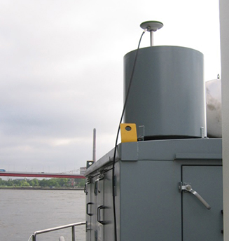
Duisburg Harbor, Germany: site of the PPP survey.
Precise Point Positioning (PPP) is a challenging surveying technique for high-accuracy results. It offers the advantage of using one dual-frequency GNSS instrument. Estimation of a PPP solution is based on the ionosphere-free linear combination for code data and carrier-phase data.
Bernese Software. Bernese software V. 5.2 is a GNSS post-processing software, using GNSS measurement data for static and kinematic surveying. It processes the data in double-difference (differential GNSS) and zero-difference (PPP solution) techniques. The software was developed at the Astronomical Institute of the University of Bern.
Bernese software contains a group of different tools or programs to complete the processing for double-difference or zero-difference mode. The estimation of the two techniques has the same processing schedule in most of the pre-processing stages. The change appears later within the parameter estimations section.
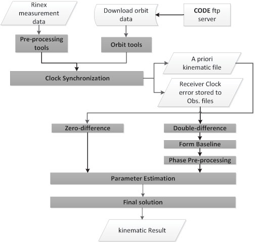
As shown in Figure 1, the processing starts with downloading the related orbits from the CODE (Center for Orbit Determination in Europe) FTP server. The orbit tools include the updating of the Earth orientation parameters to be in Bernese format, converting the satellite data to a specific format and generating the standard orbit format for Bernese software. A preprocessing program contains the smoothing of the RINEX data from outliers and cycle slips.
Figure 1. Bernese software processing schedule.
This smoothing step is following by converting the RINEX into Bernese binary format. The receiver clock is synchronized with respect to the GPS time and stored to observation files using clock synchronization tools. Using the code solution, a kinematic file is written to be inserted in the next parameter estimation procedure. For double-difference solution, a baseline is created, and this baseline is corrected from cycle slips for phase data. Parameter estimation is carried out by least-square estimation for the phase and code GNSS observations.
Kinematic PPP Solution. Bernese software provides the possibility to obtain the PPP solutions in automatic script (Bernese Protocol Engine [BPE]). The satellite orbit and clock ephemeris data from CODE center were used with intervals of 5 seconds to obtain highly accurate results. Satellite and receiver phase center offsets are considered. Tropospheric correction is applied using the Global Mapping Function (GMF) model for the hydrostatic and wet delay estimation. Regarding ionospheric correction, the estimation of the PPP solution is based on the linear ionospheric-free combination, with high-order ionospheric parameters to improve the estimation.
The ocean tidal loading correction is considered in the PPP estimation. Atmosphere tidal loading is also corrected.
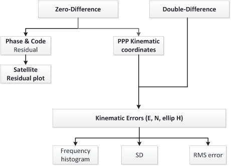
Figure 2 gives the analysis flowchart. Some outputs of the PPP solution could be visualized, such as the satellite phase and code residuals. The high residuals might come from the lower elevation angles of the satellites. Moreover, the residuals appear because of the effect of the remaining observation errors, such as atmospheric delay, multipath, or even the satellite orbit and clock residuals.
Figure 2. Flowchart of analysis strategy.
Regarding kinematic PPP solution, the error values in the east, north and ellipsoidal height are calculated with respect to the double-difference solution from Bernese software. The root-mean-square (RMS) error, which refers to the double-difference solution, and the standard deviation (SD), which is related to the mean value of the PPP solution error, are calculated, and the frequency histogram is plotted.
An antenna and a receiver were mounted on the surveying vessel to collect the GNSS data with an interval of 1 second during two days.
Experimental Work. Two kinematic trajectories were observed on the Rhine River in Duisburg, Germany, as a part of the project “HydrOs — Integrated Hydrographical Positioning System.” The project was launched in cooperation with Department M5 (Geodesy) of the German Federal Institute of Hydrology (BfG) and the Institute of Engineering Geodesy at the University of Stuttgart (IIGS) .
An antenna and a receiver were mounted on the surveying vessel (inset photo, opener) to collect the GNSS data with an interval of 1 second during two days. The virtual SAPOS (SAtellitenPOSitionierungsdienst der deutschen Landesvermessung) reference station was considered as a reference station, provided from the SAPOS-NRW team. SAPOS is a continuously operating reference station (CORS) GNSS service collecting data throughout Germany.
Results and Discussions
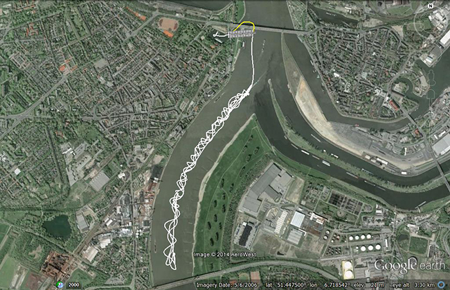
The layout of the first trajectory, which was observed for more than three hours, is presented in Figure 3. The measurements started from the inner harbour in Duisburg. The left figure shows the overview layout, and the right figure illustrates a zoom-in of the trajectory below two bridges. The white line refers to the kinematic PPP trajectory; the cross-hatched white line shows interpolated points between two solved points from the PPP solution. Because of loss of GNSS signals from the bridges, the yellow line indicates the actual vessel trajectory below bridges.
Figure 3. Layout of the first trajectory [DOY: 2014/126], zoom-in on bottom. (Photos: Google Earth)As mentioned before, the double-difference solution of the Bernese software is considered as the reference solution for the PPP solution. The PPP residuals for phase and code observations (not using double-difference solution) are presented in Figure 4. Here the residual values in phase and code have a gap because of the loss of GNSS signals, which starts from epoch 438 to 486 [GPS week second = 199845: 200115]. Additionally, there are some cycle slips from epoch 883 to 892 [GPS week second = 202105: 202150].
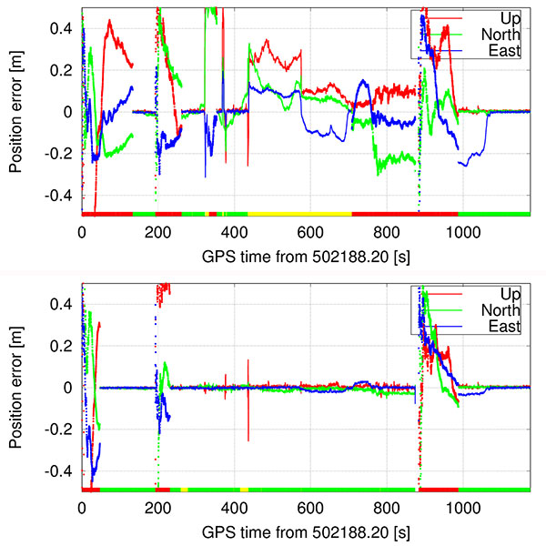
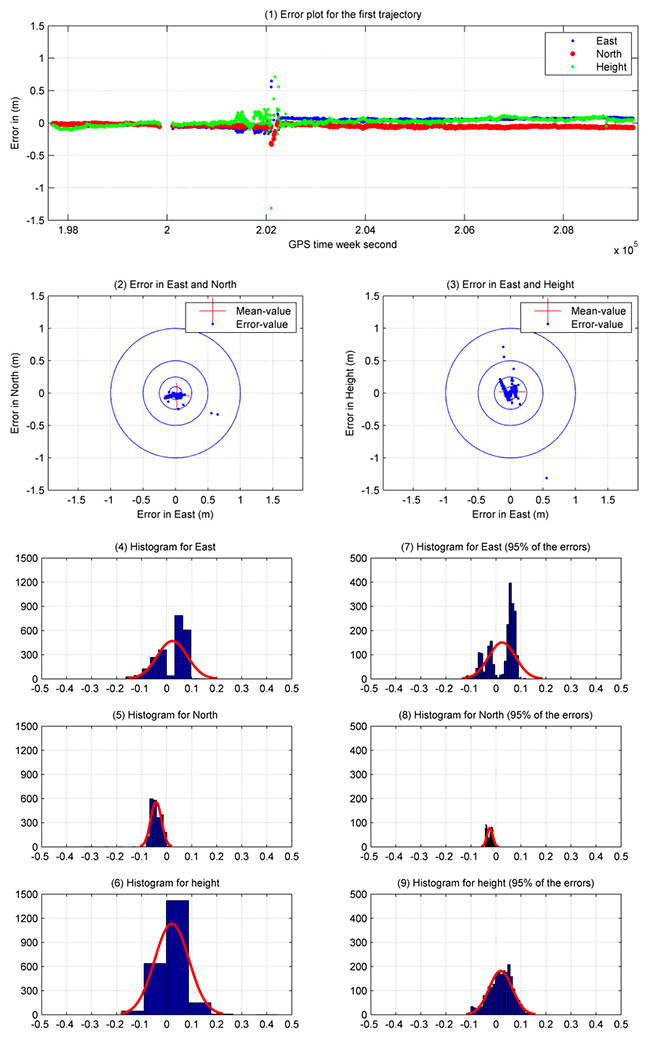
Figure 4. Satellite residuals for the first trajectory [DOY: 2014/126].To assess the accuracy of the PPP solution for this hydrographic trajectory, Figure 5 illustrates the analysis results for this trajectory between the double-difference and PPP solutions. The X-axis refers to the number of observations (one epoch/5 seconds), and the Y-axis indicates the error value in meters. Figure 5.1 shows the error plot (m) in east, north and height. As shown previously, the error values have a gap in the solution because of the loss of lock below the bridges. Moreover, there are some cycle slips later on, which decrease the estimated kinematic PPP accuracy.
Figures 5.2 and 5.3 provide the error plot for the east and north and east and height directions. The blue points refer to the errors, and the red cross refers to the mean value. Table 1 summarizes the PPP results.
Table 1. Statistical results of the first trajectory [DOY: 126/2014].Five percent of the PPP errors are eliminated to get outlier-free results. The SD (95%) of the kinematic PPP solution is obviously improved to reach 5.0 cm, 1.20 and 5.0 cm in east, north and height directions, respectively.
To distinguish between the standard deviation and the standard deviation based on 95 percent of the data, Figure 5 shows additionally the histogram of SD in Figures 5.4, 5.5 and 5.6 for east, north and height respectively. Figures 5.7, 5.8 and 5.9 provide the error with 95 percent of the results. Absolutely, the error range is improved by eliminating 5 percent of the data including outliers.
Figure 5. Analysis results for the first trajectory. Standard deviations shown in plots on the left, with outliers excluded, right.
Second Data Set. The second trajectory on the Rhine River was observed [DOY: 127] for more than 5 hours (see Figure 6). Sixteen satellites were observed during the measurement time.
Figure 6. Layout of the second trajectory [DOY: 127/2014]. (Photo: Google Earth)In Figure 7, the phase and code residuals are plotted. Some outliers are reported in this graph, which refers to cycle slips during the observations.
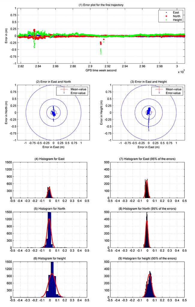
Figure 7. Satellite residuals for the second trajectory [DOY: 127/2014].Figure 8 illustrates the PPP results for this kinematic trajectory. Figure 8.1 shows the PPP error values in the east, north and height directions with respect to the double-difference solution from Bernese software.
Figure 8. Kinematic PPP solution for the second trajectory. Standard deviations shown in plots on the left, with outliers excluded, right.
The first 40 minutes of that trajectory were realized in a quasi-static observation technique (nonmoving vessel) from GPS week second 281660: 284060. The result obtained from this solution is more accurate due to the high number of satellites, and the trajectory did not include the bridges area. Figure 8.2 and 8.3 show errors in east and north, and east and height.
As shown in Table 2, the maximum and minimum values for the error range, which are presented in detail in Figure 8.4, 8.5 and 8.6, are reported in the east, north and height directions. These figures show the frequency histogram for the PPP errors. The RMS error from the solution is 2.10 cm and 2.90 cm in east and north respectively, with an RMS error of 5.60 cm in height. The standard deviation is definitely improved after eliminating 5 percent of the PPP errors as outliers. The standard deviation for 95 percent of the results shows 1.5 cm in east and north and 3 cm in height. The error histograms for 95 percent of the data are provided in Figures 8.7, 8.8 and 8.9.
Table 2. Statistical results of the second trajectory [DOY: 127/2014].The second trajectory clearly provides a higher accuracy than the first. Its data has a higher number of satellites and lower outliers than the first. Figure 8 shows the histogram of the second trajectory is similar to the Gaussian distribution curve.
Acknowledgments
The authors would like to thank Annette Scheider for receiving the GNSS measurements through the HydrOs project, our BfG partners Harry Wirth and Marc Breitenfeld, and Bernhard Galitzki form SAPOS-NRW for providing us with the reference stations.
This article is based on a peer-reviewed paper presented at the FIG Working Week, May 2015, in Sofia, Bulgaria.
Manufacturers
A Leica 1203+ antenna and GX1230+ GNSS receiver collected the data shown here.
Ashraf Abdallah is an assistant lecturer in engineering, Aswan University, Egypt, and a Ph. D. student at the Institute of Engineering Geodesy (IIGS), Stuttgart University, Germany. He received a master’s degree from Aswan University in applications of single-frequency GNSS.
Volker Schwieger is a full professor at the University of Stuttgart and director of the IIGS. He received a Ph.D. from the University of Hannover, focusing on GPS for monitoring applications.
In the temperate rainforest of the Los Lagos region of Southern Chile, where rainfall annually exceeds 1,500 millimeters and two-thirds of the days are rainy, the dense forest canopy poses a huge challenge for GNSS receivers.
Motivazion, a survey firm based in Puerto Montt, just below the rainforests, makes its living surveying in the rugged terrain under the densely canopied forest. Motivazion works primarily for hydropower development companies, surveying contours, cross sections and longitudinal profiles, as well as staking out proposed facilities. To ensure it was using the best GNSS receivers for the conditions, Motivazion conducted field tests of several sets of equipment this summer.
Motivazion owner Jorge Mesias said he typically uses a combination of total stations and GNSS receivers for his work. “If understory performance could be improved, efficiency would increase dramatically and reduce the need for using the more time-consuming total station,” Mesias said.
A light rain fell at all times during the two-day test. The test routine consisted of surveying a total of 21 points in two days. Results were compared to points established by a total station.
Base stations were set up in a small area cleared for the purpose, and the rovers moved from point to point under the canopy. Spectra Precision’s SP80 achieved fixed solutions in less than three minutes 95 percent of the time.
“The SP80 achieved remarkable results,” concluded Mesias. Geocom S.A., Spectra Precision’s dealer in Chile, provided the SP80 and technical support.
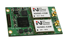
NVS Technologies AG has launched an L1 RTK+Heading GNSS receiver. The NV08C-RTK-A is fully integrated multi-constellation satellite navigation receiver with embedded RTK functionality and compatibility with GPS, GLONASS, Galileo and BeiDou.
NV08C-RTK-A is specifically designed for use in high-accuracy applications, demanding low-cost, low-power consumption, small form factor and high performance, such as construction, mining and industrial; environmental and structural monitoring; machine control and automation; parallel driving systems; precision agriculture; UAVs; and robotics and intelligent machines.
More Features
L1 GPS, GLONASS and SBAS
Centimeter-level positioning in RTK mode
Enhanced RAIM for 3D and RTK modes
Three-stage filtration for high out-of-band interference immunity
Industrial operating temperature range -40°C to +85°C
ComNav has released the M300 Pro, a CORS GNSS receiver, and the K528G, a new GNSS OEM board for heading.
Designed for reference stations, the M300 Pro tracks GPS, GLONASS and Beidou (B1, B2, B3), and will track Galileo, QZSS and other coming constellations. Its web server function enables easy and convenient remote control. The M300 Pro is compatible with many kinds of CORS software, using the standard data format RTCM and the various data transfer protocols such as UDP, TCP and Ntrip.
Raw GNSS observation data can be saved in Rinex format and remotely downloaded. The M300 Pro contains multiple ports, which can configure and connect with external sensors, including but not limited to meteorological sensors, barographs and inclinometers. The PPS output function provides a guarantee for precision timing. The M300 Pro also has the functionality of event mark and external memory.
The K528G GNSS board.
The K528G is a dual-frequency and multiple constellations GNSS board that provides the highest accuracy in differential positioning. K528G benefits from plenty of constellations signals, due to its advanced tracking performance of both GPS and GLONASS. The K528G can provide positioning and heading information generated by two antennas.
The K528G is designed for guiding and positioning construction engines, dredges, barges, shipping container cranes, mining equipment and intelligent transportation systems.


![Figure 3. Layout of the first trajectory [DOY: 2014/126], zoom-in on bottom. (Photo: Google Earth)](https://stage.globalpositioningnews.com/wp-content/uploads/2015/12/Figure-4-W.jpg)
![Figure 4. Satellite residuals for the first trajectory [DOY: 2014/126].](https://stage.globalpositioningnews.com/wp-content/uploads/2015/12/Figure-5-W.jpg)
![Table 1. Statistical results of the first trajectory [DOY: 126/2014].](https://stage.globalpositioningnews.com/wp-content/uploads/2015/12/Table1.jpg)
![Figure 6. Layout of the second trajectory [DOY: 127/2014]. (Photo: Google Earth)](https://stage.globalpositioningnews.com/wp-content/uploads/2015/12/Figure-7-W.jpg)
![Figure 7. Satellite residuals for the second trajectory [DOY: 127/2014].](https://stage.globalpositioningnews.com/wp-content/uploads/2015/12/Figure-8-W1.jpg)
![Table 2. Statistical results of the second trajectory [DOY: 127/2014].](https://stage.globalpositioningnews.com/wp-content/uploads/2015/12/Table2.jpg)