A roundup of recent products in the GNSS and inertial positioning industry from the January-February 2026 issue of GPS World magazine.
Autonomous
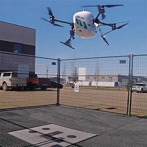
1. Delivery Drones
Volatus deploys medical supplies in Canada
Image: Trimble
Volatus Aerospace has integrated the Trimble PX-1 RTX solution into its commercial delivery drone service to achieve accurate and robust positioning and heading. The Trimble module provides Volatus’ clients with a turnkey solution for highly accurate aerial data acquisition and fully remote drone operations in real-world missions, including beyond visual line of sight (BVLOS). The PX-1 RTX uses Trimble’s CenterPoint RTX corrections along with compact, high-performance GNSS-inertial hardware to deliver real-time, centimeter-level positioning and highly precise inertial-derived true heading measurements. This technology reduces operational risks associated with poor sensor performance or magnetic interference by providing enhanced positioning redundancy.
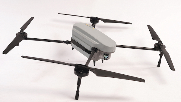
For border protection and long-range surveillance missions
Image: CopterPIX
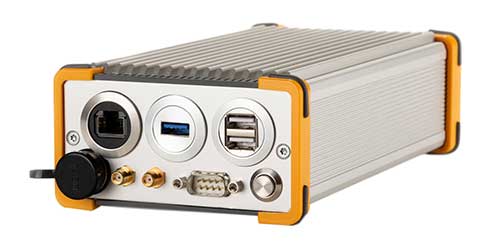
The ERE95 Mini by CopterPIX operational platform is fully capable of GNSS-denied missions and integrates a long-range, anti-jamming communication system supporting distances of more than 20 km. It has an endurance of 2 hours and can carry up to 5 kg of payload for up to 1 hour. It also has integrated daylight and thermal imaging for advanced surveillance. With a fully foldable frame, the platform collapses into a backpack-sized kit, making it suitable for rapid mobility and field operations. Its modular “puzzle” architecture allows quick adaptation of SDR modules, optical payloads, and navigation solutions, enabling mission-specific configurations. To support rapid field deployment, the ERE95 Mini features a mechanical and electrical quick-connect interface, allowing operators to switch payloads in seconds and maintain continuous operational readiness across all missions.
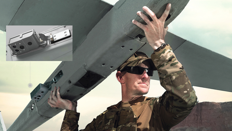
Integrated into long-endurance unmanned aircraft system
Image: AeroVironment
AeroVironment has integrated its visual navigation system (VNS) kit with the Puma Long Endurance (LE) small unmanned aircraft system, delivering GNSS-denied navigation capability. The VNS kit uses advanced computer vision and onboard processing to deliver precise, GNSS-independent navigation. Using a suite of downward-facing sensors, cameras and onboard computing, the VNS kit performs visual inertial odometry to capture and analyze terrain imagery, estimating true aircraft position in real time. The system fuses continuous visual data from the cameras with motion inputs from onboard inertial sensors to calculate precise position, velocity and orientation — allowing the aircraft to know where it is and where it is going when GNSS is not available. It automatically transitions between GNSS-enabled and GNSS-denied modes with zero pilot input, ensuring uninterrupted mission continuity in contested environments.
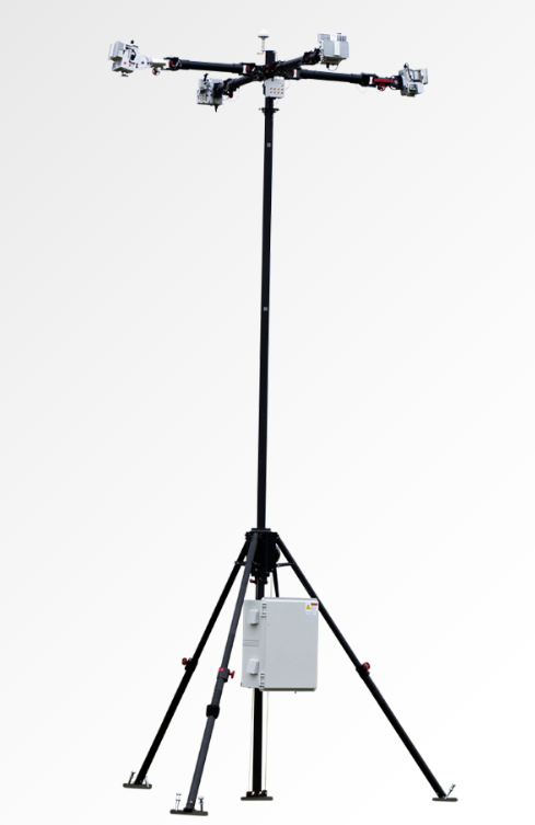
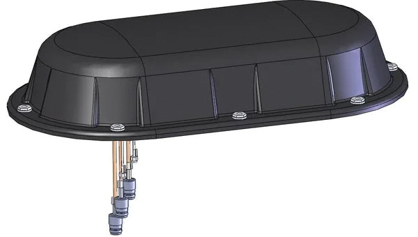
Low power, small footprint setup for close-airspace awareness
Photo: MatrixSpace
The Portable 360 Radar is a rugged, easily transportable radar kit that delivers reliable close-airspace awareness with panoramic coverage for rapid-response counter-drone operations, from safeguarding stadiums and large public gatherings to border security and battlespaces. The MatrixSpace platform unifies threat awareness across multiple networked Portable 360 Radar systems and other sensors, without compromising local operation. By combining AI edge processing with MatrixSpace AiCloud Enterprise software, central command centers get an enhanced common operating picture and deep airspace activity analytics to assure public safety.
The SatLab SL8 Laser RTK GNSS receiver combines dual cameras, GNSS, an IMU and visible laser technology to make surveying faster and easier. With non-contact measurement, image-assisted targeting, CAD live-view stakeout, and a built-in LoRa radio. It ensures smooth, reliable work even in complex or GNSS-limited environments. The SL8 achieves 2 cm accuracy within 10 meters and enables efficient data collection across bridges, tunnels, riverbanks, and other sites where traditional GNSS methods are restricted. It features image-assisted targeting through SatSurv software, displaying laser points directly on real-time images for quick and precise aiming. Its automotive-grade IMU requires no manual calibration or initialization and enhances measurement accuracy by up to 40% in GNSS-challenged areas. A built-in multi-protocol LoRa transceiver provides stable transmission beyond 15 km and compatibility with multiple RTK brands. The integrated CAD and visual stakeout functions combine live imagery with CAD data, allowing users to visualize target points on site and increase layout efficiency by up to 50%.
A complete precision mapping solution for the utility and critical infrastructure industries worldwide is the goal of a partnership between ProStar Holdings and Tersus GNSS. The partnership will integrate Tersus’s survey-grade GNSS receivers with ProStar’s PointMan Underground Utility Mapping Software, providing an affordable, field-ready solution. The partnership will use ProStar’s LinQD open API integration platform, which is designed to enable seamless interoperability between emerging technologies and legacy systems, creating a robust global ecosystem for geospatial intelligence, uniting equipment manufacturers and service providers under the initiative.
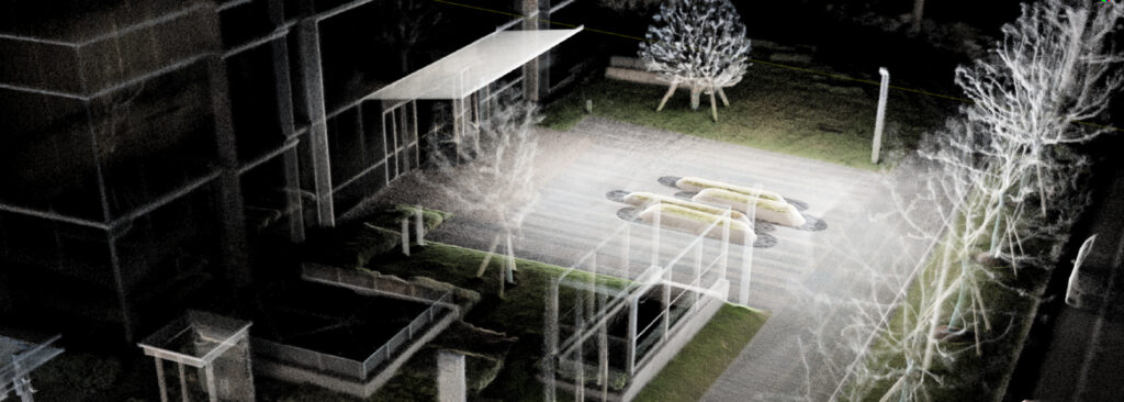
The MVP S1 RTK-SLAM handheld 3D laser scanner uses GNSS through an AI-driven RTK-SLAM workflow, as well as lidar data with imagery from dual 48-megapixel panoramic cameras. The combination provides survey-grade results in both GNSS-denied and open environments. The system achieves centimeter-level accuracy outdoors and maintains performance indoors or underground through SLAM processing. TimeSync 3.0 synchronizes the hardware, aligning sensor data at the microsecond level and supporting consistent datasets and reliable post-processing. A mobile application provides users with real-time feedback, including previews of colorized point clouds while scanning, as well as basic scan reports on site. This feature helps operators verify data completeness and quality before leaving the field, reducing the need for repeat visits. The MVP S1 supports 3D gaussian splatting (3DGS), enabling creation of textured, photorealistic 3D models. This capability is useful for building information modeling, construction progress monitoring, underground surveys, forestry analysis and industrial site documentation.
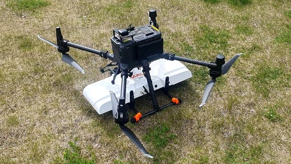
The MALÅ GeoDrone 600 and Zond Aero 600 NG are two new high-resolution ground-penetrating radar (GPR) systems for UAVs. They significantly enhance high-resolution subsurface investigations with drones, supporting applications in engineering surveys, utility mapping, archaeology, environmental studies and geophysical research. They enable surveyors to capture consistent, high-quality subsurface data in areas difficult, slow or unsafe to access with traditional ground instruments. Operating at 600 MHz, the antennas offer a balance between penetration depth and fine near-surface resolution. Typical penetration from the drone is up to 2 meters, depending on surface conditions, while SPH Engineering’s True Terrain Following ensures stable antenna height to maintain data quality and repeatability.
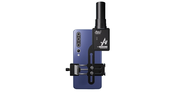
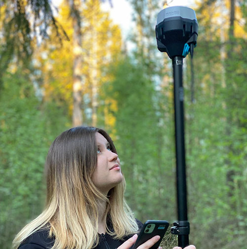
For high-precision surveying, photo surveys and 3D modeling
Image: Aurora Navigation
The Astra1 Mobile Visual RTK is a professional-grade GNSS receiver engineered to redefine high-precision mobile data acquisition. It is built to meet the demand for highly portable, reliable, high-precision tools that simplify complex field operations. At 60 grams, the Astra1 is an ultra-compact solution designed to deliver reliable, centimeter-level positioning and advanced 3D mapping capabilities through seamless integration with a smartphone and the proprietary Anypos App. Accuracy is RTK 8mm+1PPM horizontally, 15mm+1PPM vertically, photo survey <4 cm (2-15 m distance). The Astra1 allows users to capture photos with precise RTK coordinates, enabling the creation of accurate 3D models for detailed construction verification and digital twinning applications.
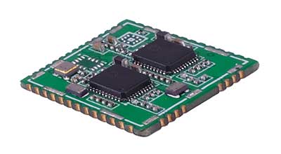
The AR588MA is a 5G-advanced (5G-A) automotive-grade cellular module that integrates dual-band GNSS supporting both L1 and L5 bands with up to 30 Hz output. Based on MediaTek’s latest-generation MT2739 platform, the AR588MA supports 5G-A communication technology and complies with the 3GPP R18 standard protocol. It features both NB-NTN and NR-NTN satellite communication capabilities and supports dual-SIM dual-active (DSDA) technology, offering improved stability and reliability on cellular connections. It also includes intelligent driving scenario recognition. Designed in compliance with the AEC-Q104 Grade 2 automotive standard, it delivers fast, stable connectivity and reliable security for in-vehicle communication and benefits on-roof applications, such as smart antennas for automotive, with higher-temperature support.
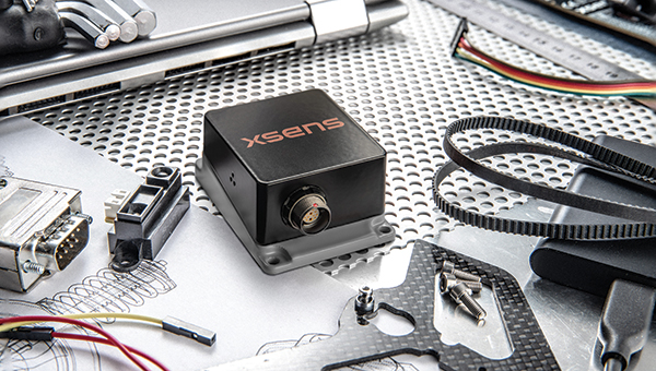
A firmware upgrade to the Xsens Sirius and Xsens Avior IMUs delivers centimeter-level vertical displacement measurements for marine stabilization and control systems. The new Heave feature enables real-time stabilization and wave compensation in a wide range of marine applications. Marine engineers can access comprehensive motion data — roll, pitch, yaw and heave — from a single compact sensor, eliminating the need for external processing or oversized tactical-grade systems while maintaining the precision required for offshore platforms, vessels, docking systems, marine robots, buoys and surveying equipment.
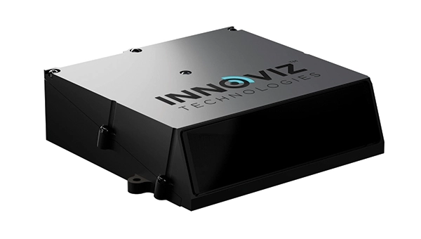
The InnovizThree is fully colored long-range lidar with camera that creates a compact sensor-fusion module designed to reduce OEM integration complexity. The solution combines lidar and RGB sensing in a single compact perception module, purpose-built for behind-the-windshield installations, drones, micro-robotics and humanoids. The consolidation of an RGB camera inside InnovizThree reinforces Innoviz’s commitment to scalable, OEM-friendly sensor-fusion perception solutions designed for series production and long-term deployment, with the potential to enable faster deployment and cost savings. The RGB sensing capabilities are factory-aligned with the lidar, enabling precise and consistent visual-to-lidar geometry across production units. This alignment, combined with hardware-synchronized capture, will enable reliable multi-modal sensor-fusion data correlation while reducing calibration effort during vehicle integration.
High-integrity GNSS integration for autonomous driving
Image: Getty Images / iStock / FlashMovie
Swift Navigation is collaborating with Nvidia to enable a scalable, cost-effective approach to autonomous driving by integrating the Nvidia Drive AGX platform with Swift’s globally referenced, centimeter-accurate GNSS positioning. Swift Navigation offloads absolute localization to the GNSS sensor stack using its Swift Automotive Suite. The suite is a complete, modular software solution for safe, high-integrity precise vehicle localization that combines the centimeter-level Skylark Precise Positioning Service with the Starling positioning engine, software that fuses raw GNSS data and corrections with IMU and wheel odometry to deliver high-integrity, centimeter-accurate positioning (PVT). By using Swift’s high-precision stack for lane-level positioning, the vehicle’s optical sensors focus on obstacle detection and safety, lowering system cost and complexity.
Sinclair’s new SM 5G Family Tier features the SM714 and SM2601 series antennas. The multi-band, multi-port antennas are engineered to deliver superior connectivity, reliability and versatility for GNSS and other mission-critical wireless transportation applications. The SM714 is a 4-in-1 low-profile customizable transit antenna that combines 5G/LTE, Wi-Fi and tri-band GNSS coverage in a single compact form. Supporting 617–5925 MHz, it enables seamless operation across all major 5G and LTE bands. It is suitable for vehicles, fleet systems and connected mobility applications requiring a discreet, high-performance solution. The SM2601D is a 5-in-1 low-profile customizable antenna that features five independent ports: one for PTC (219–223 MHz), one for Wi-Fi (2400–6000 MHz), one for GNSS, and two full-band cellular ports (694–2700 MHz) that support diversity and MIMO operation for multi-radio systems. This dual-cell configuration offers greater throughput, flexibility, and redundancy in complex communication environments.
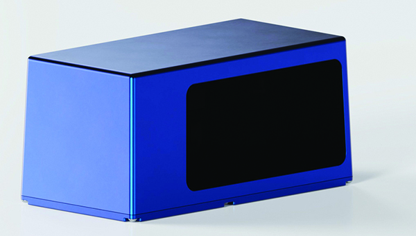
High-precision depth sensing and real-time velocity measurement
Image: Voyant Photonics
New versions of the Carbon lidar platform add 32-line and 64-line variants for compact, cost-sensitive and compute-limited systems. The new models complement existing 128-line configurations and are optimized for industrial autonomy, robotics, drones and smart infrastructure applications. They offer lower data rates and simplified integration while maintaining core FMCW advantages including velocity measurement, interference immunity and high dynamic range. With line resolutions spanning 32, 64 and 128, original equipment manufacturers and system integrators can tailor performance, bandwidth and compute load to specific use cases, from robotics and automated guided vehicles to drones and embedded edge platforms. The Carbon family’s silicon-photonics architecture integrates beam steering and coherent detection on a single photonic chip. The new variants include high-precision depth sensing and real-time velocity measurement, exceptional ambient light immunity and compact design for industrial and mobile environments.
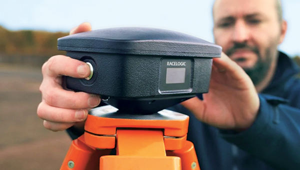
For automotive track and varied environment testing
Image: VBOX
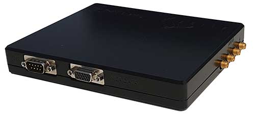
The NTRIP Base Station from VBOX Automotive combines a multi-constellation, multi-frequency GNSS engine with a built-in networked transport of RTCM via internet protocol (NTRIP) server. The equipment transmits real-time kinematic corrections over radio and cellular or Wi-Fi networks, supporting accurate real-time positioning across wider areas in varied environments compared to traditional radio-only systems. The base station launches in three models, with specifications designed to fit users’ needs. All systems combine quad-constellation, dual-frequency GNSS technology with built-in cellular and Wi-Fi connectivity. Compatible with VBOX 4, VBOX 3iS and external GNSS rovers, the new NTRIP Base Station supports both MSM4 and MSM7 RTCM formats, has up to 24 hours of battery life and is rated to IP67 to handle the demands of long outdoor test sessions. Models include Internal GNSS antenna and 2.4 GHz radio (quick to deploy for short-range applications, for temporary or mobile testing); Internal GNSS antenna, no radio (compact and simple, suitable for NTRIP or semi-permanent installations with external high-power radio masts); and External GNSS antenna, no radio (optimized for permanent installations with tripod-mounted antennas for maximum satellite visibility, supporting NTRIP or external radio).
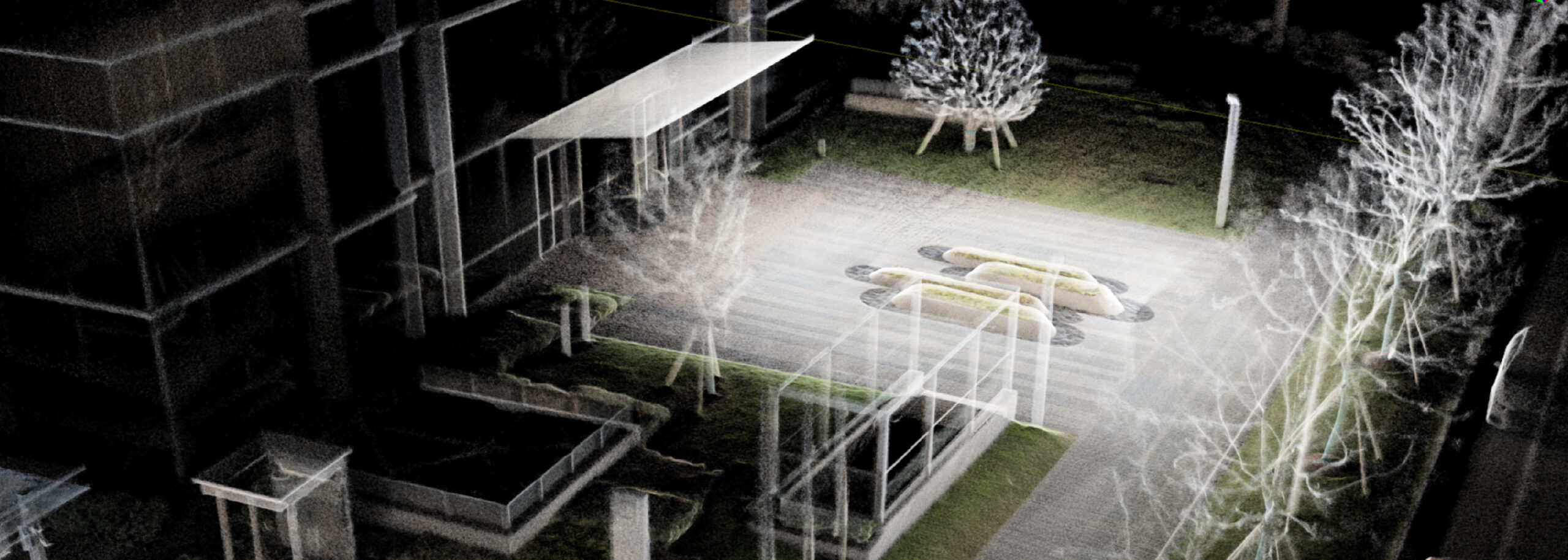
Tersus GNSS has launched the MVP S1 RTK-SLAM handheld 3D laser scanner for mobile mapping and reality capture. The MVP S1 uses GNSS through an AI-driven RTK-SLAM workflow, as well as lidar data with imagery from dual 48-megapixel panoramic cameras.
The combination provides survey-grade results in both GNSS-denied and open environments. The system achieves centimeter-level accuracy outdoors and maintains performance indoors or underground through SLAM processing.
TimeSync 3.0 synchronizes the hardware, aligning sensor data at the microsecond level and supporting consistent datasets and reliable post-processing.
A mobile application provides users with real-time feedback, including previews of colorized point clouds while scanning, as well as basic scan reports on site. This feature helps operators verify data completeness and quality before leaving the field, reducing the need for repeat visits.
The MVP S1 supports 3D gaussian splatting (3DGS), enabling creation of textured, photorealistic 3D models. This capability is useful for building information modeling, construction progress monitoring, underground surveys, forestry analysis and industrial site documentation.
ProStar Holdings is partnering with Tersus GNSS, a global manufacturer of patented GNSS technologies. ProStar is the developer of PointMan Precision Mapping Solutions and the LinQD enterprise integration platform.
The collaboration will deliver a complete precision mapping solution to the utility and critical infrastructure industries worldwide, the companies announced.
The partnership is designed to integrate Tersus’s survey-grade GNSS receivers with ProStar’s PointMan, providing an affordable, field-ready solution available through Tersus’s international distribution network. Tersus GNSS has operations in China, the United States, and Australia, and is recognized for its innovation in GNSS receiver and base station technology for high-precision positioning applications.
The collaboration represents the latest step in ProStar’s strategy to expand its partnerships through the LinQD open API integration platform, delivering its technologies in one connected precision mapping solution.
ProStar’s LinQD platform is designed to enable seamless interoperability between emerging technologies and legacy systems, creating a robust global ecosystem for geospatial intelligence. By uniting equipment manufacturers and service providers under this initiative, ProStar continues to strengthen PointMan’s position as a premier mapping solution for the critical infrastructure industry worldwide.
For tough shots in complex construction sites, Lee Landman says that tilt make impossible shots possible. (Image: Lee Landman)
Prior to the advent of tilt compensation for surveying and construction GNSS rovers, there were incremental approaches to tilt, with limited success. However, five years ago, “no-calibration tilt compensation” was first incorporated as a standard option for rovers. Some users remain skeptical or exercise the same caution as they did when such innovations as EDMs were first introduced. Nevertheless, the adoption of tilt compensation — for appropriate tasks — has spread rapidly. How did we get to this point?
For centuries, plumb bobs and bubbles were the only viable options to level an instrument or pole about a point. Early references to spirit levels appeared in the 15th century; however, siphon style water levels may have been in use in ancient Greece, China, and elsewhere for much longer. In more recent centuries, various types of level vials became a standard feature for surveying transits, theodolites and levels. Vials with a slight upward curve position a bubble between defined center marks when level.
Circular, convex glass bubbles appeared for industrial applications in the 19th century and were soon incorporated into surveying instruments and survey poles. In recent decades, electronic bubbles, or “e-bubbles” emerged, using microelectromechanical (MEMS) tilt sensors along with various methods to apply an orientation to compute the position of the pole tip relative to the phase center of the GNSS antenna. This is in contrast to relying on a bubble alone to orient the phase center directly above the pole tip.
There are both pitfalls and potential productivity losses if the pole has to be leveled solely with a bubble for each measurement; we’ll examine these later. If freed from the bubble — as electronic bubbles, tilt sensors, and various methods for orientation enable — how much productivity gain can be realized? For which tasks do the users find tilt compensation most useful? For which do they not? We talked with manufacturers, dealers and field users to find out.
Early adopters
Tilt for safer surveying. (Image: Lee Landman)
Lee Landman owns a firm in the Cape Town area of South Africa that provides construction layout, civil engineering layout and related topographic mapping services. Landman obtained a Trimble R12i GNSS rover, with no-calibration tilt, shortly after its release in 2020.
“Tilt is my go-to tool for almost all tasks now, except layout that needs better than 15 mm to 20 mm tolerance,” Landman said. “For topographic mapping, I will get everything possible with tilt, and then use a total station to get the points I can’t with the rover.”
Landman reports productivity gains of 30% to 50% on certain jobs. His crews will try to leverage a tilt rover for as much of a job as they can, provided it meets precision needs. For checking work, such as grade checking or layout verification, they will try to use tilt for everything first. Then in any areas that look suspect, they will set up a total station to confirm. He said this saves a lot of time up front.
After several years of use, Landman said there are specific tasks where they will not use tilt, and we find this echoed by other users interviewed (and from my own tests). For instance, construction layout of such structures as walls and columns where a consistent 5 mm to 10 mm tolerance is required. He said the same applies for tasks where precise elevation is key, such as on road curbs and final road levels. However, he noted: “That’s a GNSS precision thing, not a tilt issue.”
Landman provides other caveats,“I am nervous using tilt on long rods or when you constantly change rod height, as the results of using a wrong rod height would be disastrous, and the deflection on long rods could also degrade the results.”
Summarizing the overall impact on his operations, Landman explained, “We have become more competitive. Not by sharpening our price, but by the fact that using tilt is less fatiguing and faster to do layout and data collection. That gives us an edge over firms that are not using it.” He provided the example of a foundation layout that needed 300-400 points laid out and chalked in an hour or two so that the excavators that were standing by could start digging as soon as possible. “It normally takes two to three moves of the pole and bubble checks to get a point on position without tilt,” Landman said. “Now, when you are doing 300 points, that is 600-900 times that I don’t have to look at the bubble and adjust the rod. The amount of energy and fatigue that saves is just outstanding. No sore lat muscles and eye fatigue.”
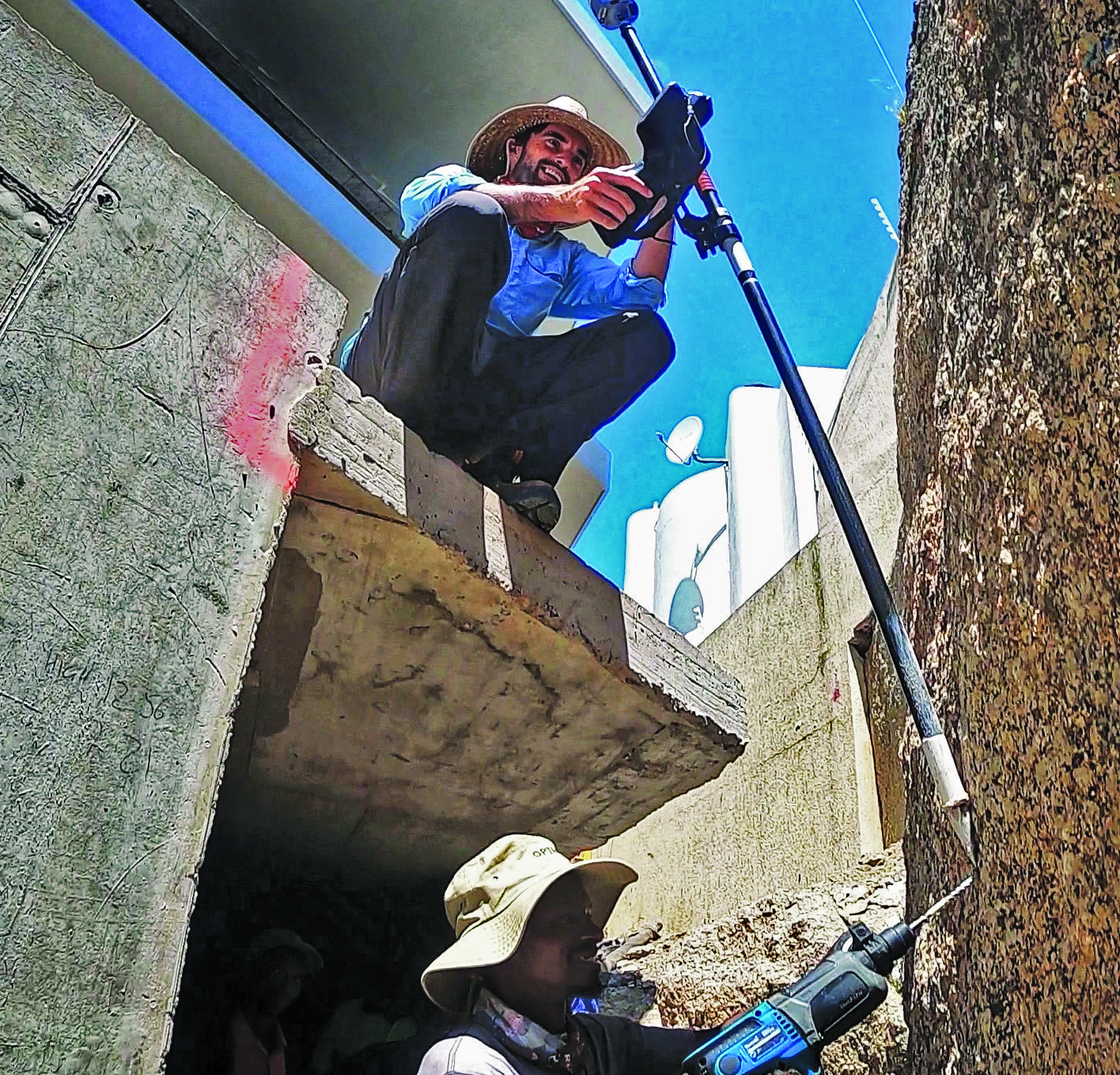
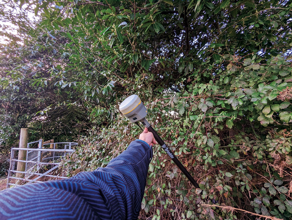
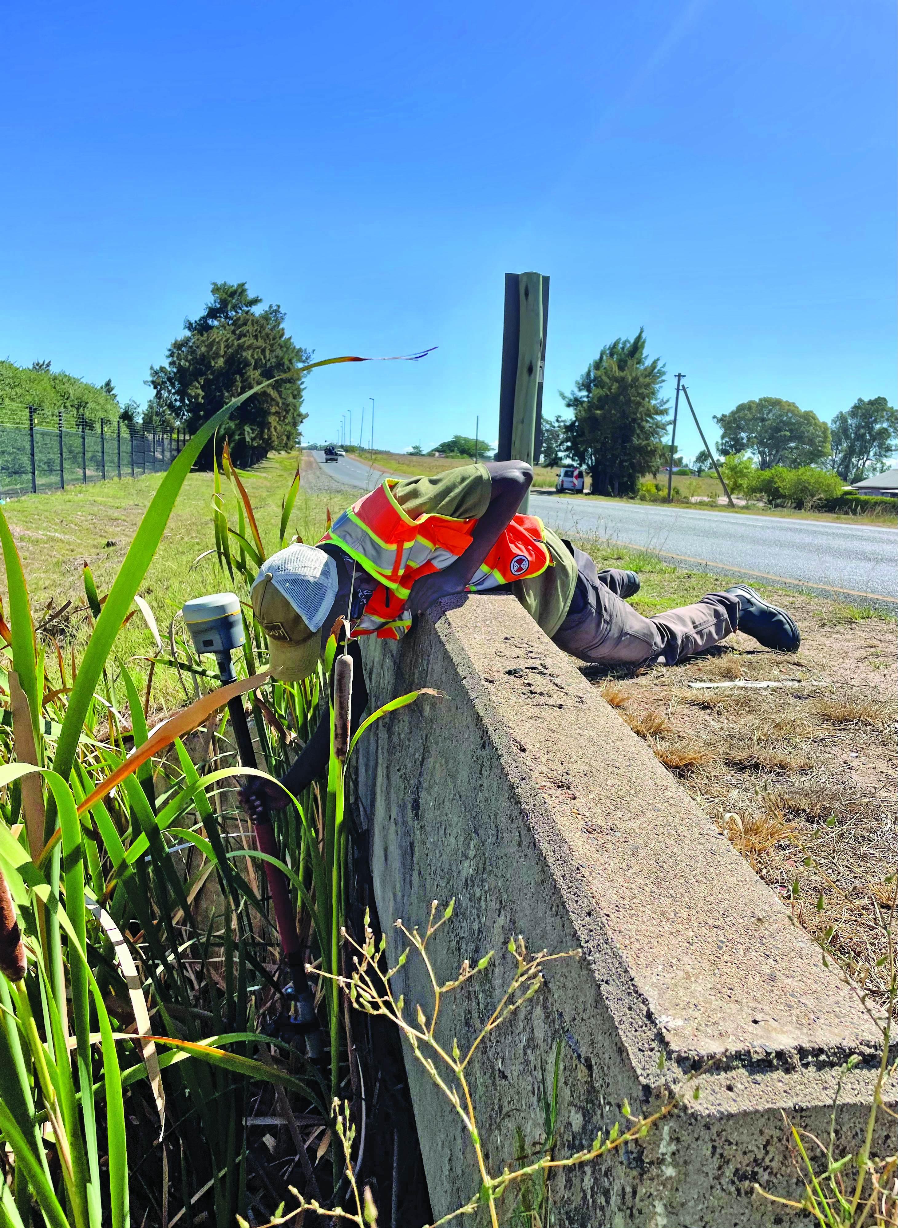
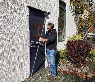
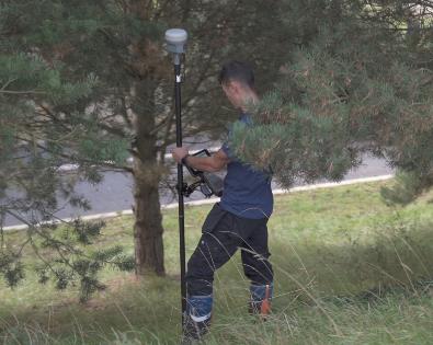
In the southwest of England, where Benchmark Surveys operates, fields and roadways are often lined with thick brambles, making if difficult to shoot features underneath them, such as utilities. James Richards of Benchmark says tilt has revolutionized the way they survey, enabling shots in places where even a total station (where the rod needs to be plumb) cannot take them. (Image: Benchmark Surveys)
Then there are shots that you cannot get with a bubble plumbed pole, Landman said. For instance, in checking rebar layouts prior to construction, as well as marking out on or below the steel rebar cages for plumbing points, voids and slab penetrations.
“Previously we could not easily do this, as you cannot get the pole plumb for total station shots or GNSS to place or check a point,” Landman said. “You just have to check positions on the steel for a column or wall to see if it has enough concrete cover or is in the right position prior to pouring concrete.”
James Richards is the survey manager for Benchmark Surveys, a family-owned and operated firm in the southwest of the UK that has steadily grown its portfolio of services. In part, this growth has resulted from their willingness to embrace new and emerging technologies. This included adding tilt compensated R12i rovers to their instrument inventory shortly after they became commercially available.
“We use tilt on every surveying task where we can use GNSS,” Richards said. “Tilt has enabled us to complete numerous jobs where we would have otherwise only been able to use a total station.” Apart from control, there are not many tasks for which Richards would not recommend using tilt, “It has helped improve our surveys. We can capture data quicker and easier than before and with greater accuracy.” Examples of daily challenges his crews face include getting shots in and around ditches, field boundaries, and boundary fences in foliage, and walls with foliage overhang. These are now easily captured using tilt.
“Tilt has had an enormous impact on our business. We complete work to a higher standard, capturing data quicker and easier,” said Richards. “It helps us capture data that was not possible without offsets. We’ve seen a rise in profitability since using tilt. Surveyors seem to be happier with day-to-day work, knowing that they can capture the data required to meet our high standards, and clients are also happier when receiving more data than expected from surveys.”
Stages of adoption
CHC Navigation is a GNSS developer and manufacturer that has sold hundreds of thousands of units over the past 15 years. They were quick to develop and implement tilt compensation technology, which has now become standard on all of their current models.
Rachel Wang, product manager of CHC Navigation’s Surveying and Engineering division explained the four stages they undertook in developing tilt.
“In the first stage,” said Wang, “users had to rely on the survey pole’s bubble to maintain a centered state, which had significant limitations in terms of measurement accuracy and accessibility.”
In addition to any GNSS error, there could be additional error due to a poorly calibrated bubble, a pole that is not straight, misalignments with each joint of telescoping rods, and user error in trying to keep the bubble lined up while simultaneously operating the field collector (if not using a bipod). Often it seemed that a surveyor would need extra hands and an extra set of eyes.
“The second stage introduced the first generation of tilt compensation using an electronic compass,” said Wang. “Although this technology enabled the first tilt measurements, it was hampered by problems such as low accuracy, tedious calibration, poor reliability, and susceptibility to interference from electrical currents or magnetic fields.”
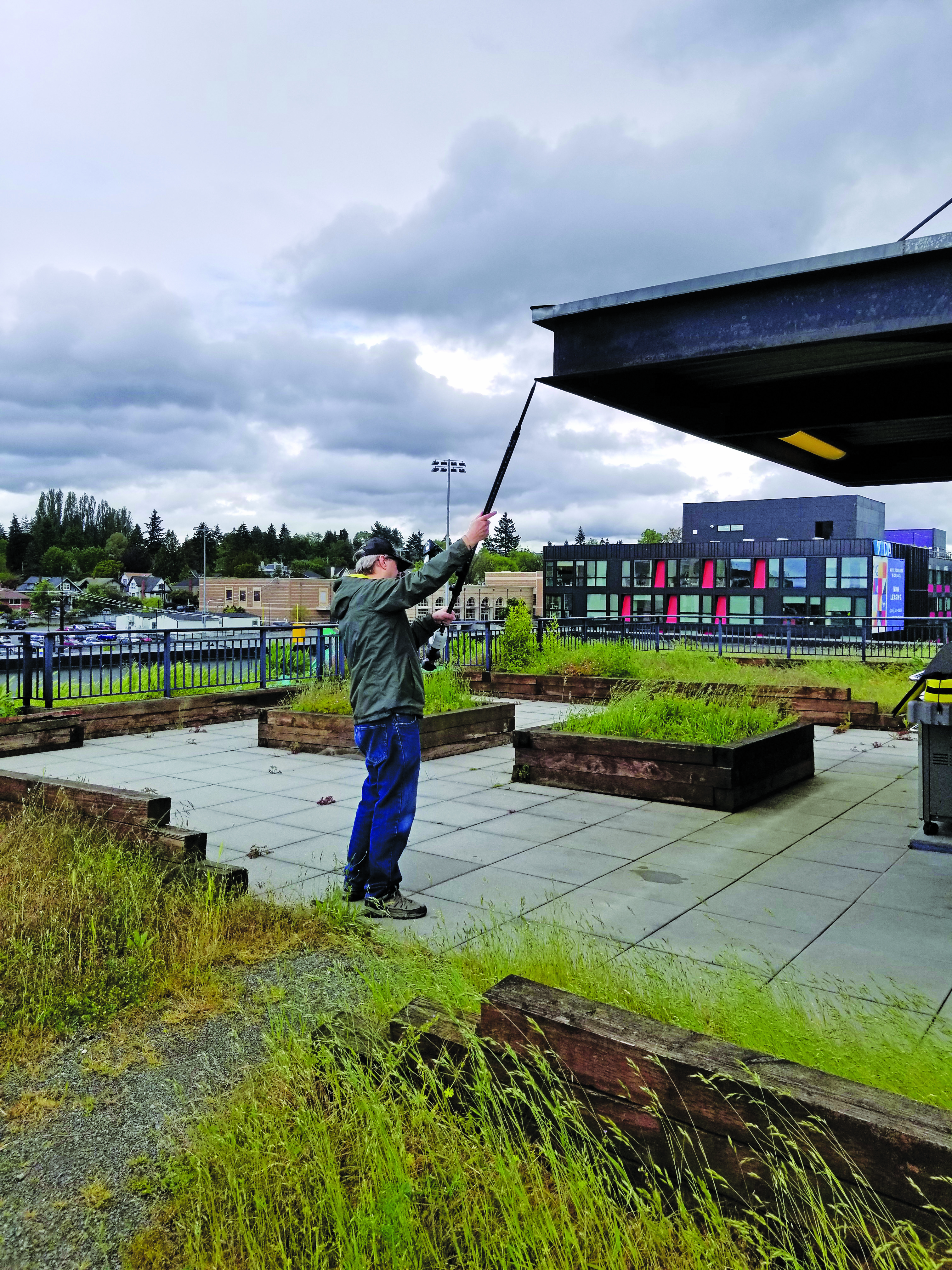
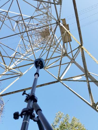
Common applications for tilt features include getting shots up against structures and improving sky view. For example, for this bridge column with sky partially obstructed by the bridge deck. (Image: CHCNAV)
Such magnetic oriented tilt compensation had been implemented on rovers several years prior to no-calibration methods, by manufacturers that included Javad, Trimble, Topcon, and others. The calibration step often involved rotating the rover vertically in eight or more horizontal positions. This was cumbersome, and the orientation quality changed over time, mostly unbeknownst to the user. It was no surprise that “mag tilt” never really caught on, and unfortunately it made some users wary of tilt in general, even when no-calibration solutions came along.
“The third step was the development of the second generation of tilt compensation, using hybrid positioning based on GNSS + IMU,” Wang said. “This technology was less affected by magnetic interference, but still required initialization of the IMU by shaking the survey pole.” I had tried several models from manufacturers of early “minimal calibration tilt” enabled rovers. For each, a certain amount of movement had to be induced on the pole, by walking around a bit, swinging the pole back and forth, or in a circular sweep. It often did not take more than a minute or so, and then normal moving around on the site would usually keep it calibrated. This was a tremendous step up compared to the old “mag tilt.”
“More recently, we are proud to announce the fourth step in our tilt measurement technology integrated into our new i93 GNSS RTK rover,” Wang said. “Our Auto-IMU technology further simplifies the IMU initialization process by observing acceleration at some point between startup and RTK operation. This replaces the previous repeated shaking of the survey pole for initialization. In fact, users can initialize the IMU while walking or moving normally. In addition, once initialized, the IMU feature is not easily lost even if the pole is carried on the shoulder, held horizontally, or even upside down.”
Wang said that all current CHC survey rovers are equipped with their newest tilt compensation technology. Since the international launch of their first CHCNAV GNSS RTK with IMU, the i90 GNSS in 2019, they have continued to incorporate this feature into all subsequent GNSS rovers. “Based on feedback from users, we know how valuable this feature is,” said Wang. “That is why we have made tilt compensation a standard feature on our current i73, i83, i90 and i93 models.”
Uptake
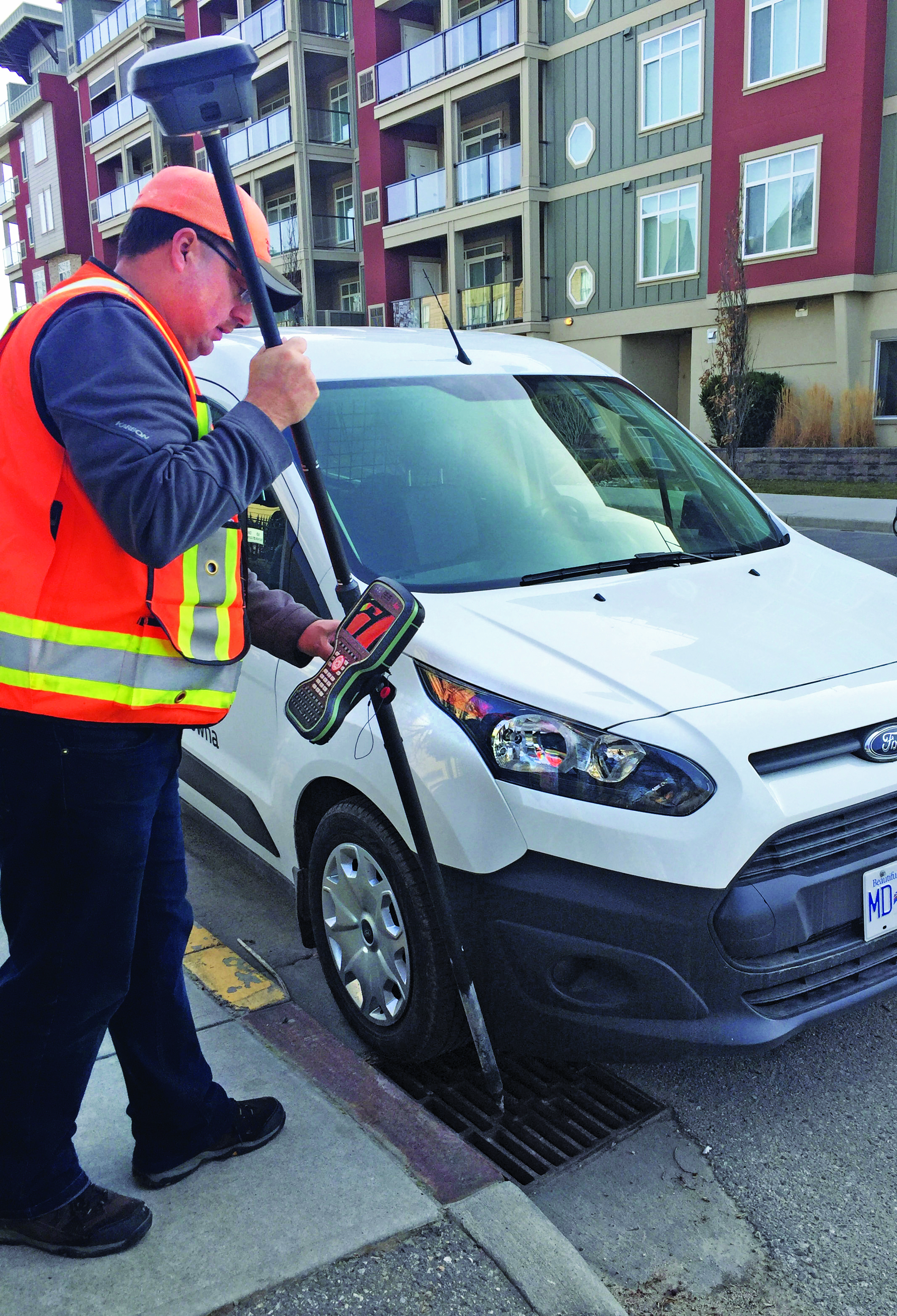
Greg Maier of the City of Kelowna, Canada, was an early adopter of tilt. He found it invaluable to access hard to reach features, such as this inlet under a car, and for safer surveying along the edges of roadways. (Image: Greg Maier)
For the past year, I’ve been talking to other GNSS manufacturers, their dealers, and customers, together with monitoring the subject in surveying and construction groups and forums online. Manufacturers have reported overwhelmingly positive feedback from dealers and customers about the tilt function. Typical feedback focuses on convenience and time savings of not having to level the pole manually.
“Based on our research, we have found this feature to be extremely useful for surveying and staking out on construction sites,” Wang said. “It has increased speed and efficiency by up to 30%.” I have heard similar statistics from each of the manufacturers contacted, as well as their dealers, and most of their customers that have used tilt.
There are common threads to much of the feedback from various sources: the tilt function is now an indispensable tool for many surveying applications.
As Wang noted, “While some users still prefer to use the traditional bubble to plumb the pole, we have seen a clear trend toward adoption of the tilt function in the field. The benefits of tilt, such as faster and easier surveying, are becoming more apparent to our users. As we continue to improve the accuracy of our tilt-compensation, we expect that more and more users will choose this convenient feature over other traditional GNSS rovers in the future.”
Another common observation (no pun intended): even if the pole-tilt feature offers significant convenience and time-saving benefits, it may not be the best option for tasks that require very high accuracy, such as surveying control points. For such tasks, manufacturers, dealers, and users recommend using the traditional bubble on a pole with a bi-pod mount for more accurate measurement.
As something completely new, the uptake across the surveying profession and for construction took time to grow. “It took quite a while to catch on here,” said Keith
Belsham, branch manager for Spatial Technologies, a measurement solutions dealer in the Vancouver region of British Columbia Canada. They specialize in solutions from Leica Geosystems and were an early provider of the Leica GS18 T, widely recognized as the first GNSS rover with no-calibration tilt.
“My perception is that in the United States and some other countries, there are more companies trying to stay at the top of technology,” Belsham said. “However, in our region surveyors are very cautious and need to do a lot of checks and look to see how others respond before they consider it. It was that way with other new technologies; I have memories of numerous total station demonstrations, when prism-less EDM’s were first coming out, where surveyors would pull out a tape measure to check whether the instrument was giving the correct distance.”
About three years after the introduction of no-calibration tilt is when Belsham said it really took off in his region, and it is now quite popular. He gave an example of a customer buying a Leica GS16 (no tilt), saying that they did not see a need for tilt, considering the extra expense. They then upgraded a week later once they were in the field and recognized many instances where the tilt would have saved them time.
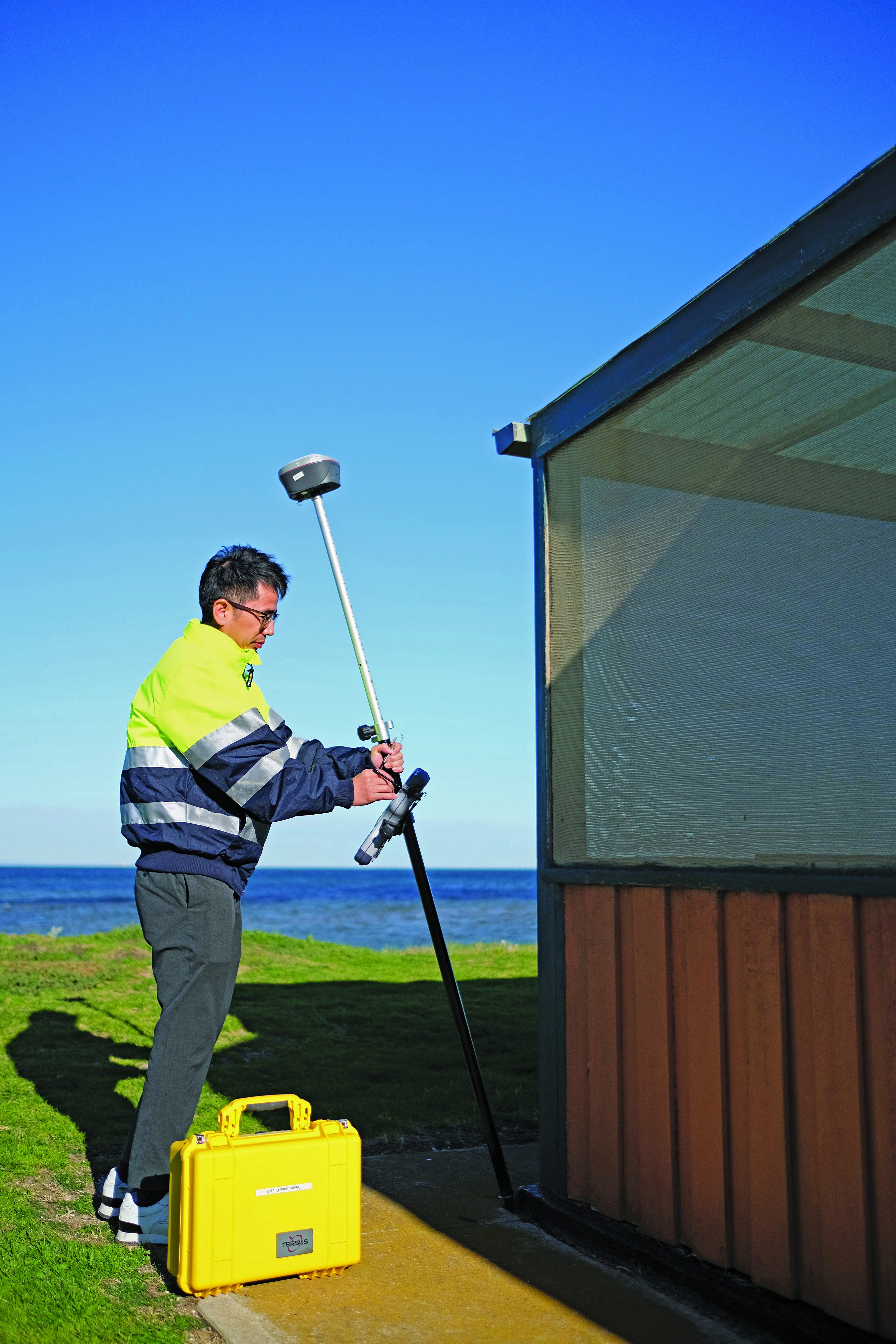
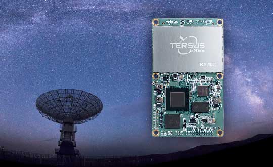
Rather than go the OEM route, Tersus GNSS developed its own GNSS board, positioning engines, and IMU tilt integration. (Image: Tersus GNSS)
A Spatial Technologies customer that has found tilt useful for numerous applications is Lucas Geomatics, a surveying firm based in Surrey B.C. “When I set up GNSS units for construction companies, tilt is great as they don’t have to be super accurate,” said Peter Smith. “I mean, here’s a machine with a bucket that’s 3 f wide, and the bucket is about an inch thick. The grade checked does not have to be super accurate for the machine to hit it, because end users in construction companies do not have to do precise surveying. They’re great guys who dig trenches and tilt gives them more than enough precision for their needs.”
Among the many uses Smith has found for tilt, he has also adapted it in a very creative way to deal with areas of deep foliage. A common approach to working in thick foliage is to raise the GNSS rover up on a tall or extended pole; this can increase the number of satellites viewed and reduce multipath. However, working with a bubble low enough on the pole to see makes it quite difficult to keep the rover at the top sufficiently still and plumbed over the tip. I remember some clever (albeit questionable) solutions folks cobbled together to help plumb very tall poles, such as a small live video camera pointing down over a bubble near the top of the pole to view on a phone. Smith said that tilt solved this problem, and he uses various tall rods, including one that extends to as much as 12 m. He chose a non-conducting pole, such as those used by utility companies for high foliage.
He does prefer to use the rover on a bipod, though, and bubble for control and points requiring very high precision. He sets the data collector software to log positions at 5 Hz or 10 Hz (standard in most systems) and has the software average multiple positions over the course of a minute or more.
Smith said that tilt has made a lot of difference in their surveys, especially where they want a lot of productivity, but do not need very high precision. Part of why he is impressed with the GS18 T is that they had upgraded from an older system, that only used two constellations, to full constellation support on their new rover.
Stability through motion
It sounds counter to one of the key principles for surveying measurement: the instrument and pole must be kept very still. However, in other data collection technologies, including aerial mapping and mobile mapping, leveraging predictable motion, acceleration, and trajectory caught on decades ago. There are numerous integrated GNSS + IMU solutions from, for instance, Applanix and NovAtel, that are the key positioning components for kinematic mapping systems. Such integrated sensor solutions are also in broad use now for UAV real-time and post-processing workflows.
One challenge for integration into survey rovers, was miniaturization. Additionally, such solutions needed a wealth of satellites and signals to be usable at tilted angles. The Galileo and BeiDou constellations reached full complement at about the same time as no-calibration tilt was introduced. Some manufacturers even integrated new antenna designs to better utilize satellites at tilted angles, for example in the Leica GS18 T.
The electronic bubble aspect of such solutions was in some ways the easiest to achieve. Depending on the quality of components, multiple tilt sensors can measure the angle of tilt at precisions matching, or even bettering that of typical pole bubbles. Plus, they are built into the rover boards with a direct relationship to the axis and phase center, whereas the bubble is external, down on the pole.
Integrated IMUs, with as many as nine axes, are highly sensitive, as are accelerometers (if an integration utilizes those). Skeptics always point out that IMUs are subject to drifting over time. However, the observed high-rate GNSS positions and motion sensors are continuously updating the calibration of the IMU. It is true of no-calibration tilt systems that if you hold the pole still too long, it will lose its calibration. Or if you move it too fast. Though on every tilt rover I’ve tried, I moved it around vigorously and spun it (more than would happen in normal operations) and it still kept its calibration. There can also be instances of environments with excessive multipath hazards — such as heavily wooded areas, urban canyons, or congested construction sites — where users often find it best to turn off the tilt for certain shots.
Industry penetration
Tilt for shooting inverts. (Image: Lee Landman)
While manufacturers have approached the GNSS/IMU solution in varied ways, the fundamentals are the same. Once some of the major vendors developed and integrated tilt, they began offering this feature for OEM customers, and in recent years we see tilt on many other brands worldwide. There are relatively new players in the market that took a different approach, developing not only their own GNSS boards and positioning engines, but IMU solutions as well.
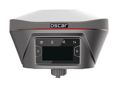
Tersus GNSS has rapidly gained a presence in various global markets, though relatively new in North America. While starting as an OEM, the company pivoted to developing its own boards in 2015, and GNSS + IMU integrations more recently. It recently published a paper about what they call its “Extreme RTK Solution” that has a section with data from their own tests for both plumbed and tilted observations.
I did some quick tests with a Tersus Oscar Ultimate, at various angles of tilt, and in mixed environments. The results aligned closely with those in the paper, as did tests with other tilt rovers. I have had the opportunity to try rovers of several different brands, to check precision at various tilt angles against points established with static observations (to see how much the tilt added to the total error). While these were not comprehensive tests, I did compare notes with surveyors who did their own tests, and we’ve all been finding out the practical limits of tilt. Perhaps part of why tilt took a while to catch on was that surveyors needed some time with these units in real-world environments, to get a feel for sweet spots for tilt for different tasks that have specified error budgets.
To get an idea of potential productivity gains, I did a small topographic survey of an area I had previously surveyed with a conventional rover, total station, and scanner. The total station and tilt-less GNSS took about the same amount of time — but with tilt it took about half the time. Many variables can and do come into play, but the figure I keep hearing of up to 30% efficiency gain for many applications seems realistic. Certainly, for asset and resource mapping, tilt could easily fit the looser precision requirements.
As for degradation at various angles of tilt, checks against static points (beyond standard GNSS error) showed negligible differences under 5°, 1 cm up to 15°, 2 cm or more around 45°, and 3 cm or more at 60°. This was just a cursory look, and indeed any surveyors that use tilt should do their own testing. I did notice in the data that when doing simple topo shots, just moving around the site, the pole did not often exceed 5°. Therefore, moving around quickly and efficiently for topo, not having to look at the bubble, improves productivity without significantly compromising quality.
Layout, as surveyors and construction folks who use tilt say, can be quite a snap compared to the old “plumb-shoot, move-plumb-shoot, move-again-plumb-shoot, etc.,” process. You simply move the tip of the pole around until you are on the point.
Enabling further sensor integration
Tilt compensation has now extended to non-GNSS tech, for instance Leica Geosystems AP20 prism poles (used with robotic total stations). (Image: Gavin Schrock)
No-calibration tilt, and multi-constellation GNSS, have enabled further developments that may not have been practical otherwise. Leica has since added an image point extraction feature to its GS18I. This marries the tilt and a camera with a clear path to processing the images in the data collector software. With tilt running, and at ranges under 6 meters, you can roughly aim the camera side of the rover toward say, features under an overhang, that you would not otherwise be able to shoot with a GNSS alone. You walk past the features as the camera takes a series of images. Then, in the software, you identify the points in multiple images and photogrammetrically it gives the offset. You can also process the image series into point clouds. There were several attempts at this sort of solution in the past by various brands. However, without tilt it was too cumbersome as you would need to stop and plum for each image in the series. As one user told me, the new image point features are “like having a UAV on a pole.”
Tersus GNSS has taken a slightly different approach to their image point solution. You pick the point you desire in the camera view on the data collector, and then move along as the software automatically identifies the same point in subsequent frames, until it has enough matches from multiple angles to calculate the offset. CHC Navigation has just announced its own image point feature, with a two-camera integration in the i93 Visual GNSS RTK rover.
Pole tilt also has been integrated into non-GNSS solutions. For instance, the recent release of a prism-pole tilt solution by Leica, the AP20. A constant stream of positions of the prism, from the total station, takes the place of GNSS in this application. They’ve also included a rather clever automated pole-height feature.
What could be next? Perhaps small solid state lidars on rovers, or combined lidar/camera solutions such as on an iPhone/iPad, or a tiny SLAM scanner (that could also aid in position stabilization)? Not to mention what might be coming in the not-too-distant future in the realm of quantum sensing.
In considering all feedback about no-calibration tilt, it seems it is very much here and here to stay. There are many who love it and try to use it for everything (perhaps, in some cases, too many tasks). For others, it is conditional love: use where appropriate. While others still hate it immediately, perhaps on principle, though I find those folks typically have never tried it. Legacy tools and methods provide comfort and known levels of risk. New features such as tilt, provided some time is spent gauging its performance and appropriateness for various tasks, can deliver productivity gains that should prompt reevaluation of some long-held assumptions.
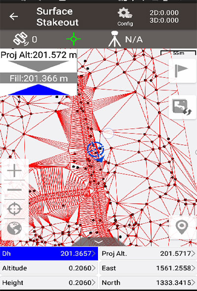
Tersus GNSS has updated its surveying smartphone app, Nuwa. The latest version includes features such as vector map import and digital surface stakeout.
The Nuwa app runs on Android and is reliable, and easy to operate. It has rich and powerful functions that can help surveyors complete measurements more efficiently and accurately.
The app is designed to work with the David and Oscar GNSS receivers from Tersus GNSS, plus other receivers that support NMEA-0183.
New features in Nuwa version 2.3.3.2 include:
Vector map import and stake. The new version supports importing vector maps in DXF, LandXML, KML, and KMZ formats in the import module, optimizes the loading speed of vector maps for display in the Survey and Stakeout interface, and allows direct clicking to select points and lines on vector drawings for staking.
Digital surface stakeout. The new version supports importing DXF files containing 3dface entities and LandXML files containing surfaces, manually selecting points to form Delaunay TIN, and entering surface offsets for fill and cut value interpolation calculations in Surface Stakeout.
Update version description. Now, when receiving a version update, the highlights of the latest version are displayed directly in the application, including essential or market-focused features and fixes for issues.
Existing features of Nuwa include:
Ability to configure base, rover and static surveys
Graphical interface with background map (online/import)
Tersus GNSS has released a white paper on ExtremeRTK Technology. According to the company, the white paper demonstrates how ExtremeRTK Technology delivers excellent performance in all manner of surveying scenarios and describes its impressive compensated results when performing tilt surveys — even tilt at angles greater than 90°.
As a professional real-time kinematic (RTK) developer and manufacturer, Tersus believes the stability and accuracy of RTK are the cornerstones of RTK measurement.
According to the paper, “ExtremeRTK integrates the receiver’s hardware, high-precision baseband IC [integrated circuit], RTK engine, GNSS/INS coupling algorithm, etc. It enables unprecedented performance stability in challenging environments and prevents occurrences of occasional RTK positioning outliers.”
Tersus starts from scratch — engineering each element from its foundation in the physics of GNSS. From signal capture and baseband tracking engine to position-velocity-time (PVT) results and the overall algorithm of RTK, Tersus completes all algorithm logic independently.
The white paper discusses:
signal tracking and multipath mitigation capabilities
fix speed in open-sky and challenging environments
accuracy when performing RTK control/detail point/continuous point surveys
GNSS/INS tilt compensation.
Test results described indicate the remarkable performance of ExtremeRTK technology in RTK initialization, accuracy and tilt compensation. Based on ExtremeRTK, Tersus will continue to invest in the further development of RTK receivers by adding photogrammetry, laser scanning and more.
Meanwhile, Tersus will also focus research and development on professional industry software, the integration of resources in data management, and big-data applications so it can provide users with additional professional services.
Approaches to providing real-time kinematic (RTK) solutions at high rates have existed in various forms for decades, providing value for high precision applications. This technique is nearly universally adopted in the industry, and many surveyors may have been using it for years without realizing it. Yet there are persistent misconceptions about the subject.
By Gavin Schrock, PLS
For many on the development side of high-precision real-time kinematic (RTK) GNSS, like those we interviewed for this article, the incorporation of high-rate solutions into their RTK products is a given — and has been for a very long time. Yet, in some end-user communities there may still be many question marks: Does my gear do it? Does other gear do it? What can it do for me? What are the pluses and minuses?
We asked for insights from 10 prominent firms that develop and manufacture RTK-enabled high-precision GNSS solutions and equipment, spanning multiple applications:
By high rate, we mean higher than 1 second (1 Hz) increments, such as 0.2 second (5 Hz), 0.1 second (10 Hz), etc. Part of the confusion about high-rate RTK is that there are two scenarios. One is transmitting corrections from a base or network at high rate, receiving and solving on-the-field sensors or rovers at a high rate (for example, 5 Hz base + 5 Hz rover).
The other is base transmission of corrections at a lower rate and receiving/solving on the rover at a higher rate (for example, 1 Hz on the base + 5 Hz or more on the sensor/rover).
While both can be valuable for different applications, what has been adopted as standard for most surveying, construction, agriculture and mapping applications is the latter.
What are applications that would run the base and rover at higher than 1 Hz? “Moving Base” applications are prime examples, where you are seeking to resolve positions for one or more sensors relative to a base that is also on a moving platform. Think of a barge on the ocean where a helicopter (or rocket) might be landing. Here is a definition from the user manual for a popular OEM receiver that has been in many makes and models since 2003:
“Moving Baseline RTK is an RTK positioning technique in which both reference and rover receivers can move. Moving Baseline RTK is useful for GPS applications that require vessel orientation. [For example, the] reference receiver broadcasts [correction] data at 10Hz, while the rover receiver performs a synchronized baseline solution at 10Hz. The resulting baseline solution has centimeter-level accuracy. To increase the accuracy of the absolute location of the two antennas, the Moving Reference receiver can use differential corrections from a static source, such as a shore-based RTK reference station.”
Beyond such specialized applications, running the base at a high rate is a burden on radios or bandwidth. Additionally, as industry experts explain below, it is of little (or no) value and may only unnecessarily use excess bandwidth and burden broadcast radios.
When would you run the base at 1 Hz and the rover at higher than 1Hz, such as 5Hz, 10Hz, or more? When the base is static. That pretty much covers nearly all surveying, mapping, precision agriculture and construction applications. What is meant by high rate in the sensor/rover receiver and its RTK engine, in the context of such applications? As one of the firms interviewed stated:
“The number of RTK position fixes generated per second defines the update rate.”
For most of the surveying, mapping, precision agriculture and construction applications, that means base 1 Hz + rover 5 Hz or 10 Hz. Then there are specialized applications, such as structural monitoring and geophysical studies, that may run sensors/rovers at 20 Hz, 50 Hz or (though rare) as high as 100 Hz. Whether a higher rate is a default, or 1 Hz is the default, changing the rate is almost always a user-configurable option.
A general perception is that base-rover gear defaults to base 1 Hz + rover 1 Hz. However, as the experts below note, that is not necessarily the case — often the rover rate is higher by default.
By any other name…
The respective approaches, and their appropriateness for different end-use applications, may seem fairly straight forward. However, part of the confusion about the subject for end users comes from the wide range of terminology used to describe how high rate is applied across the industry.
The understanding of processing approaches is clear among GNSS engineers, and in specific terminology, but this rarely gets translated well or consistently in terms meaningful to end users in documentation or marketing.
Developers might have different approaches to achieving high-rate solutions and would of course not wish to completely reveal their cards, but many of the fundamentals are the same. A mutual recognition of parallel development among GNSS engineers, and the manufacturers they develop for, in that each strives to continually improve solutions, means that the high-rate element of RTK generally does not get much marketing hype.
Often, when high-rate RTK does get laterally mentioned — in manuals, marketing or labeled as configuration options in GNSS field software — the mix of terms can confuse the user. Such terms as extrapolation, prediction, update rate and solution rate could evoke a negative connotation to an end user who is used to hearing one set of terms, and they might view otherwise like terms as contrasting terms.
GNSS engineers do not have issues with mixed terms. As some indicated in their respective interviews, they seem a bit puzzled as to why anyone would misunderstand the subject, and how marketing spin might lead users to be confused.
In recent years, the subject seemed to get discussed a lot more than usual in various high-precision end-user social media platforms. Perhaps this was a natural progression in growth of understanding of the nature of GNSS among these constituencies, and a desire to know more about what goes on in those black boxes — a positive thing. There may also have been some instances of marketing nudge.
For whatever reason it became a subject of discussion, we heard from readers who asked us to look into it. So here, in alphabetical order, are insights from of the experts in this field. You can jump ahead to the specific section for your equipment vendor, but we encourage you to read through each; combined, they provide a more complete picture of the subject.
Bad Elf
With Larry Fox, VP for Marketing and Business Development
Larry Fox uses the Bad Elf Flex. (Photo: Bad Elf)
Bad Elf has long provided GNSS solutions for aviation- and mapping-grade field applications. Several years ago, the company introduced a survey-grade-precision system, Flex. It is offered with an option for a modest initial investment in the hardware, and an innovative token system for enabling and operating at centimeter precision.
Larry Fox has been in the industry for a long time and has seen the evolution of real-time GNSS. He is Bad Elf’s vice president for marketing and business development, but he also had a key role in the development of the Flex system. Fox said that, of course, high-rate RTK is supported. “We allow options up to 20 Hz on the rover if the user has this enabled.”
For the approach of 1-Hz base and higher rates on the rover, he said that Bad Elf does not have a specific term for this. “For purposes of description, I could refer to it as high update rate, but I suspect high solution rate is pretty much synonymous.”
Fox explained how the standard approach works. “The rover knows the location of the fixed base and therefore applies the same processing techniques by simply reusing the last received data.”
He also mused about various hypothetical scenarios. “Given that the converse is also possible — a slow data rate from the base, say, 0.2 Hz at the base and 1 Hz at the rover — is there fundamentally any difference?”
For many applications, Fox does not see a substantial advantage in running at higher rates: “I see no benefit for higher data rates in a static situation such as a survey. I would argue that in a survey workflow, one should allow the RTK algorithm to settle over the static shot being taken, as the RTK algorithm likely benefits from aging out some of the data it used while moving.”
He adds, “I would suggest that once you have occupied a point for a modest amount of time and you remained fixed, I can’t see any benefit. My argument here is that by the time you have leveled and prepared your collector of choice, any decent RTK receiver with a good sky portrait and good corrections will not observe any benefit.”
As for disadvantages and trade-offs, “More and faster data,” Fox said, “must be better, correct? Sarcasm included. Unless there is a tangible need for more samples, what is one going to do with all the extra data? I could have seen a possible argument that a single constellation receiver may benefit from averaging, but that could be a be a whole different subject as multi-constellation is now standard. Arguably, at a higher data rate one could capture more epochs and reduce the time on station. With multi-constellation receivers I am just not convinced that these techniques have the same merit they may have had in the past.”
Bad Elf doesn’t support higher correction transmission rates from the radio. “The current module only supports RTCM3 at a 1Hz rate,” Fox said. “Even if we could transmit faster, the payload required would exceed the capability of the message transmission rate of the radio. The battery life of a radio is directly correlated to the transmission duty cycle. The more you are transmitting, the less battery life you will have. I would argue this would impact the useful field time you would have without an external battery solution.”
Fox notes that any application where a rover is moving — such as on a vehicle or for machine control — could benefit from high rate. “I could see a potential application for drones,” he added. “I would want to have the epoch of an image recording very tightly coupled to the image captured. Fundamentally, an RTK drone’s imagery is only as good as that. If one was taking video at any reasonable framerate, a higher frequency RTK GNSS may benefit the geolocation of more individual frames with less extrapolation.”
What about rates higher than 20 Hz? “We have run our receiver up to 20 Hz on the rover side. Although there are units capable of even higher rates, I don’t have any data that would convince me that this is viable, for mapping or surveying.”
I asked about some of the misunderstanding out there about high-rate RTK, and Fox replied, “We can be creatures of habit and tie ourselves to beliefs that ‘this is the way I did it and it worked then.’ People should always ask themselves the question, ‘do I still need to do it this way?’ Again, there is the premise that more is better. I can’t tell you how many times I have seen people collect very high-rate data for lines and poly features only to decimate the data because it reduced performance, increased storage, or lowered the performance of the apps rendering the data.”
Emlid
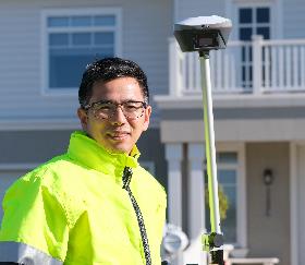
With Svetlana Nikolenko, Lead Application Engineer
Photo:Svetlana Nikolenko with an Emlid GNSS receiver. (Photo: Emlid)
Emlid, a relatively new entrant to the market for high-precision GNSS, has made a splash with their line of affordable systems, such as the Reach RS2 rover and base-rover kits, and RTK systems for UAVs.
“All our devices support this,” said Svetlana Nikolenko, lead application engineer. “We do not have a special term for this, as it is simply a standard. We recommend 5 Hz and higher for a moving rover, but it can be overkill for a stationary one.”
Asked why one would want to run at high rate, Nikolenko explained, “The need to set a higher update rate depends on the rover’s velocity and acceleration. The higher the update rate, the more solutions per second are calculated. So, if you’re moving fast, the higher update rate simply allows you to keep your position current. If the rover is stationary, there are no issues with working at 1 Hz. Still, there is nothing wrong with running a stationary rover at 5 Hz or higher: it is excessive, but produces more samples with different satellite geometries.”
For moving applications such as UAVs, higher rates are of value. “It really depends on velocity,” Nikolenko said. “For example, if the rover is on a drone flying at a speed of 5-20 m/s and the update rate is set to 1 Hz, you won’t have the actual positions of the images. The higher update rate our devices have is 10 Hz, and at a drone speed of 20 m/s, even if you take photos each second (which might be a bit excessive), you’ll get accurate positions.”
Using an Emlid receiver in harsh conditions. (Photo: Emlid)
Emlid does not support a moving base. However, if there is a strong demand from users, they will consider adding this. For non-moving applications, Nikolenko said, an approach of broadcasting from the base at a high rate is excessive. “This increases the load on the radio (or any other connection link) because the base sends its position and corrections to the rover as often as it calculates it. Anything excessive simply adds load to processors and batteries.”
CHC Navigation
With Carlos Cao, Technical Manager for the Asia-Pacific region
CHC Navigation, or CHCNAV, has steadily grown as a recognizable brand of GNSS and other geospatial products internationally. While the brand might be new to some in North America, in some regions of the world CHC has a substantial share of the market, selling hundreds of thousands of units over the past 15 years. The company develops its own solutions, but also incorporates OEM components. In all cases, CHCNAV has provided high rate as standard from its earliest days.
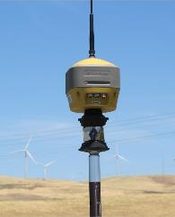
Multi-constellation rover with tilt compensation. (Photo: Schrock)
Carlos Cao, technical manager for the Asia-Pacific region, said that his company supports the approach of broadcasting at 1 Hz and solving at higher rates on the rover. “For example, you can get coordinates every 0.2 seconds in the Landstar 7 Topo Survey software,” said Cao. “Meanwhile, with different OEM boards, RTK models and supported software, [the equipment] can also reach 10-Hz or 20-Hz static data recording and NMEA data output (including GNGGA coordinate data).” Their term for solving RTK solutions at a high rate on the rover is “high update rate.”
This can bring advantages, specifically for moving applications, Cao said. “When you stake out, the 5-Hz update rate brings faster coordinate updates, especially when surveyors walk quickly. When you survey by time during movement, you can get denser points; while you survey by distance, the accuracy will be better if you are at high speed. For example, speed is 6 m/s, and you want to survey a point every 5 meters; 1 Hz update rate cannot do this with high accuracy.”
When would 1Hz be sufficient? “Normally,” Cao said, “a 1 Hz update rate is enough for a topography survey because users won’t survey at a high speed, so our default setting is 1 Hz, though you can choose higher rates if enabled and as needed. Unless you are moving, however, such as when some surveyors mount a rover on a vehicle, there is no significant difference in the final results.” He added that running at high rates can drain the battery faster.
Broadcasting at higher rates has several major issues. “With more satellites launched, especially BeiDou, correction data becomes much larger,” Cao said. “It means that network RTK requires more data flow, and UHF radio RTK needs a UHF modem that can send data at a high rate. It is a very big challenge for base RTK.”
Meanwhile, notes Cao, “The rover could even have a correction age of 5 or 10 seconds, and it will use the previous package to calculate the position. Since 1-Hz base and 5-Hz rover can work without degradation of precision, there’s no need to change the base to 5 Hz.”
Other applications CHC supports often use higher rates. “Navigation, machine control and precision agriculture normally use a 10-Hz, 20-Hz or 50-Hz update rate,” Cao said, “because these devices work under high-speed movement status, especially navigation. Also, they need to combine with high-update inertial measurement unit (IMU) data. The max update rate is 50 Hz. Normally the application data for these uses is NMEA data output by COM port or TCP/IP protocol. For surveying applications, such as topography, 1-Hz base and 5-Hz rover is enough. For other applications that need higher rates, we also provide such devices.”
Hemisphere GNSS
With Kirk Burnell, Senior Product Manager
Kirk Burnell
“At Hemisphere, we simply refer to this as RTK,” said Kirk Burnell, senior product manager for Hemisphere GNSS. Burnell added that they do not have any special term for this — it is simply a standard.
We were discussing specifically the approach of solving on the rover at higher rates than the base corrections. “All Hemisphere RTK products can work in this way, meaning corrections can come in at 1 Hz or slower, and rover output can be at 1 Hz, 5 Hz or 10 Hz as the user sees fit and as the application demands.”
Hemisphere develops GNSS and multi-sensor solutions for many industries: surveying, construction, agriculture and more. While Hemisphere has its own branded survey rovers, its OEM boards are in many other popular rover brands, makes and models. So, whichever you are running, you get high rate as a standard option.
Hemisphere’s receivers are frequently used in construction applications. (Photo: Hemisphere GNSS)
Burnell explained further that this is a given in the industry. “This is the standard expectation for RTK amongst our competitors, based on their product offerings, documentation, and standard operation. When describing RTK, the expectation is for 1-Hz base-station corrections, and a user-selectable rover output rate. Understandably, when people discuss RTK in technical terms, they may use different phrases to help distinguish between different techniques, which is why there might be different phrases out there. For us, it is simply RTK.”
As for the benefits of high rate, Burnell explained that inside the receiver, the measurement engine and RTK algorithms are typically running at 10 Hz or 20 Hz, and the selected output rate of the solution does not impact the RTK engine’s performance. The receiver will fix as fast and as accurately as possible given the quality of the RTK correction stream. Survey users could see a smoother update rate on their screen using 5 Hz compared to 1 Hz. This makes such tasks as leveling the rod or watching the change in height on screen while moving from the bottom to the top of a curb feel more natural. The user is not waiting an extra second each time to see the stability of the output. “A 5-Hz update rate is a good tradeoff for smooth workflows versus consuming CPU and battery power, compared to 10 Hz or 20 Hz,” he explained.
Would there be a disadvantage to simply running the rover at 1 Hz? “When using a 1-Hz update rate to the data collector, there will be fractions of a second spent waiting for the screen to update,” Burnell said. “Over the course of a day’s work, this could add up to a few minutes of extra time spent. In reality, this does not impact the ability to deliver a job on time. If the user does not feel impeded by the slower update rate of the screen, there is not a significant difference between the quality of the data, comparing 1 Hz and 5 Hz.”
Addressing one misconception that some users have about high rate, that it might significantly improve precisions, Burnell clarified, “For classic RTK surveying, outside of the workflow differences for the surveyor, the same quality of data is produced.”
Disadvantages? “Once you move beyond 5 Hz you start to exceed people’s hand-eye coordination ability, and the benefits diminish,” said Burnell. “Additionally, the data collector has a lot of communication to process, data to unpack, calculations to do, and screen refreshes to accomplish. Faster than 5 Hz leads to stresses in these aspects of the user experience, and ultimately can consume the data collector’s batteries at a faster rate.”
There have been instances of high rate being marketed as enabling users to save a lot of time, but as Burnell noted, this might actually be a potential problem. “There could be a false sense of having no latency, which could lead to rushing through a job, increasing the chances of making a mistake. A surveyor’s observations and measurements are the currency of their trade, and they should be made with care and attention to the work being done. Most surveyors take pride in a job well done.”
Regarding the other scenario, broadcasting at a high-rate and solving on the rover at the same high rate, “This mode of RTK operation has little or no benefit and a host of drawbacks,” Burnell said. “The biggest issue is the volume of data. For a multi-frequency multi-GNSS solution, there is an immense amount of data to be transmitted from the base to the rover. Running a link at 5 Hz requires huge data bandwidth generally only possible using an internet link as compared to a 450-MHz or 900-MHz radio link. Drawbacks for internet links are data volume costs. For dedicated radio links, the issue is most likely to impact radio range. To send five times as much data, the over-the-air baud rate needs to be five times greater. This means that the energy per bit of data is five times less when at high speed. The signal will lack the ability to punch through obstacles. While some may suggest that having five times as many corrections reach the rover compensates for this, some radio protocols can be configured to transmit multiple retries with 1-Hz data.”
However, there are advantages to running at higher rates for specific applications, Burnell said. “If data is being collected in a kinematic fashion as compared to shooting individual points, there will be more detail when collecting at 5 Hz. For example, driving along a road with a receiver mounted to the roof, in 1 minute of driving there will either be 60 measurements at 1 Hz or 300 measurements at 5 Hz. For many non-survey applications, this is critical. For example, at highway speed, 1-Hz data means 1 point every 30 meters (100 feet) or so. In machine control, the systems are not relying on hand-eye coordination and reaction time, and 20 Hz or 50 Hz are common speeds. Autonomous applications also typically use between 10 Hz and 50Hz for GNSS, and often combine this with 100-Hz or 200-Hz IMU data. Aerospace and defense applications have demanding conditions and use 100-Hz to 200-Hz IMU data to navigate, often combined with 1-Hz, 10-Hz or 20-Hz GNSS data.
There are even some applications for which it is warranted to broadcast corrections at rates slower than 1 Hz. “One example was a user in Japan, where radio links are often throttled to 4800 baud,” said Burnell. “They were looking to see how to slow down corrections to less than 1 Hz so that they could take advantage of multifrequency multi-GNSS RTK. Another example: I recently asked for some 10-Hz rover data for analysis. With very large files, analysis took much longer — I wished I had asked for 1-Hz data!”
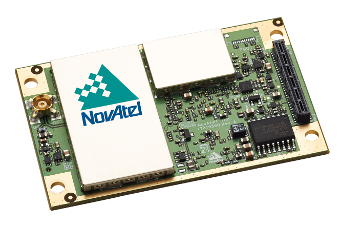
Hexagon | NovAtel
Hexagon | NovAtel is a prominent tech firm providing positioning, navigation and timing (PNT) solutions for multiple industry segments, including defense, surveying, construction, agriculture, autonomy and more. While GNSS is a core technology, NovAtel develops multi-sensor systems (including inertial) and has a broad reach with its OEM products. Surveyors, for instance, might not be familiar with NovAtel first-hand, but have likely used its technology via NovAtel’s many OEM customers.
Iain Webster
Iain Webster, senior director of Geomatics and Software Engineering for NovAtel, said that not only does NovAtel support high-rate RTK, but the customer can choose the position output rate desired — 1 Hz, 5 hz, 10 Hz, 20 Hz, etc. — and the receiver will output RTK positions at that rate.
“We distinguish between a matched solution (where a correction is matched with a rover observation at the same time tag), and a low-latency solution, where base observations are extrapolated for position computation at the rover,” Webster said. He provided a description from a company manual:
“The RTK system in the receiver provides two kinds of position solutions. The Matched RTK position is computed with buffered observations, so there is no error due to the extrapolation of base station measurements. This provides the highest accuracy solution possible at the expense of some latency, which is affected primarily by the speed of the differential data link. The MATCHEDPOS log contains the matched RTK solution and can be generated for each processed set of base station observations.
The Low-Latency RTK position is computed from the latest local observations and extrapolated base station observations. This supplies a valid RTK position with the lowest latency possible at the expense of some accuracy. The degradation in accuracy is reflected in the standard deviation. The amount of time that the base station observations are extrapolated is in the “differential age” field of the position log. The Low-Latency RTK system extrapolates for 60 seconds. The RTKPOS log contains the Low-Latency RTK position when valid, and an “invalid” status when a Low-Latency RTK solution could not be computed. The BESTPOS log contains either the low-latency RTK, PPP or pseudo range-based position, whichever has the smallest standard deviation.”
NovAtel does not brand this as a specific feature — it is just a standard part of its RTK solutions, but the company refers to it in their documentation as a “low-latency” solution.
The main benefit of this solution, Webster explained, is for kinematic users to allow better representation of their actual trajectory (such as in applications on moving vehicles). “The higher the dynamics, the more impact the latency of the matched solution will have to the point that we recommend the low-latency solution to all but specialist customers with known static positioning needs. For surveyors, there may be improved workflow with the low-latency solution as they will be able to move from point to point more quickly.”
NovAtel produces GNSS and inertial hardware and software, including OEM boards, for multiple applications. (Photo: NovAtel)
Webster noted that for applications where the rover is static for observations, 1 Hz can be fine, but for moving rover applications — kinematic — running at 1 Hz is probably unacceptable, so low latency is quite standard.
Additionally, he pointed out, there are applications where longer periods between corrections may not necessarily be detrimental. “Note that some manufacturers, including NovAtel and Leica, offer the possibility of using PPP corrections to extend RTK solutions beyond, for example, a 60-second timeout,” Webster said. “There are various proprietary methods to achieve this, but ultimately the RTK solution could be extended without limit in this way.”
Are there tradeoffs to using extrapolation or other high-rate approaches? “With corrections coming in at 1 Hz,” Webster said, “there is very little error over that period, so for most users, there is little disadvantage and perhaps some productivity advantage with a higher rate. If there is any trade-off, it is between getting the highest accuracy possible versus the lowest latency solution.”
As for the other scenario — the base broadcasting at greater than 1 Hz and the rover solving at greater than 1 Hz — “There is little advantage,” Webster said, “except in some specialized applications such as when the base is moving (called moving baseline) to provide a cm-level baseline between the base and the rover for relative positioning. For typical surveying applications with a static base, the rover would have to wait until the corrections arrived before outputting a solution. Other downsides include increased bandwidth on the communication link and more loading on the rover CPU, meaning lower battery life.”
What are the non-surveying applications where a high rate (in either scenario) can yield a specific benefit? Webster noted that, in fact, they deal mostly with non-surveying applications. “Most use cases need 10 Hz or 20 Hz for machine control or precision ag. We do have some very specialist applications that have required up to or beyond 100 Hz — but it is often best in those cases to do a GNSS/inertial navigation system (INS) solution and use the IMU to output at that a high rate. As previously mentioned, there are other specialist applications where the base is moving. In this case, we run a matched solution at a high rate between the base and the rover.”
Leica GeoSystems
With Xiaoguang Luo, Senior Product Engineer, GNSS Product Management Group
Rover with calibration-free tilt compensation and camera-based offset point capabilities. (Photo: Schrock)
Leica Geosystems (part of Hexagon) has been a major global developer and manufacturer of GNSS systems for multiple disciplines for several decades, introducing its first GPS receiver, WM101, in 1985. Since then, Leica has been among the leaders in GNSS receiver innovation, including integrated systems such as a rover that incorporates calibration-free tilt compensation and an image-point capture feature (GS18 I). Therefore, it is no surprise that for Leica Geosystems equipment features high-rate RTK as standard.
Xiaoguang Luo is a senior product engineer in the GNSS Product Management group at Leica Geosystems. He confirms that this option is supported in all Leica Geosystems RTK rovers of the current product portfolio, and this option is enabled by default in the Leica Captivate (surveying field) software. A term Leica Geosystems uses is prediction for its high-rate RTK approach.
Xiaoguang Luo
The standard positioning rate is 5 Hz on the rover. “As far as GNSS processing is concerned, there is no fundamental need to go to higher positioning rates,” Luo said. “The need for high rates is mainly driven by applications. For example, we are using the 5-Hz position update rate at the rover by default for an improved staking workflow and user experience. The 10-Hz rate is also supported in Captivate, for example, when streaming NMEA messages.” He added that 10 Hz is supported for other applications, such as structural monitoring, and 20 Hz for machine control.
As for the advantages of a rate higher than 1 Hz, Luo said that working at high observation and solution rates enables the possibility of modeling fast-changing error effects with a period below 1 second, and allows for high-rate non-surveying applications such as bridge monitoring. Does a high rate have any significant effect on the final results? He said that it strongly depends on the use case where high-rate observations and positions are involved. In addition, the quality of prediction also affects the final results.
Bernhard Richter
By this he means that while the standard approach for applications where the base is stationary, such as surveying, can work so well with a base data rate at 1 Hz and rover at 5 Hz, the key conditions do not change much over a single second.
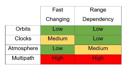
Luo’s colleague Bernhard Richter, vice president of geomatics, explained it. “To understand this, you need to separate the elements of corrections into those that are fast changing and range dependent (see the graphic below). If the errors change slowly, then they can be estimated and predicted very well. Or, if the range dependency is low, errors could come from a different source than the base station. If the range dependency is medium or high, then the corrections are more difficult to estimate on the rover side, but if such errors change very slowly, they can still be predicted very well with the precondition that corrections have been received at least once.”
The rate of change and dependencies for the elements of corrections. (Source: Leica GeoSystems)
You’ll notice that multipath is high in both regards. This brings up another misconception about high-rate RTK — some users have an expectation that it will improve their performance in limited sky-view situations (like thick tree canopy) or high multipath environments. This is not so. Any improvements in such environments come from having more satellites, more observations, and more modernized signals. With regard to high-rate and multipath, Richter said, “It is anyway futile, since multipath decorrelates so quickly that the advanced mitigation has to happen both in an analog and a digital way on the rover.”
While there are benefits to running at high rate, such as for staking, a balance has to be struck — for instance, in not running it at too high a rate. Luo outlined disadvantages that must be considered when performing high-rate RTK.
High processing load and battery drain, particularly with multi-constellation and multi-frequency RTK.
High temporal correlations between observations, which may not be considered in a sophisticated manner in the RTK algorithms.
High base rates provide challenges for the RTK data link devices, such as radios.
In addition, he noted that while any kind of predictive solution will introduce some amount of error, that would be so small in, for instance, a base data rate at 1 Hz and rover at 5 Hz solution, as to not even be noticeable in the positioning results.
Septentrio
With Bruno Bougard, Research and Development Director
Bruno Bougard
“Our rover solution computes RTK up to 100 Hz,” said Bruno Bougard, R&D director at Septentrio. “Update rate requirements for industrial machine control applications are typically 20 Hz. This is necessary to capture the motion dynamics. Also, it is not only the update rate that matters in those applications, but also the latency, which should be low (<20 ms typically) and constant.”
Septentrio NV is a designer and manufacturer of high-end multi-frequency GNSS receivers and integrated solutions. Markets they serve include surveying, mapping, construction, science, timing, agriculture, marine, autonomy, and more — all with specific applications where high-rate RTK may be employed They also provide OEM boards and modules for further integration by others.
Surveying users for instance may be familiar with their Altus line of rovers, such as the NR3, where high rate is a standard option. “There are new applications where a higher update rate is required,” said Bougard. “Surveying with UAV, using photogrammetry or lidar scanning requires at least 10Hz. In mobile mapping in general, RTK-INS solutions such as SPAN, Applanix or Septentrio SBi, require update rates up to 200Hz.”
Bougard acknowledged that manufacturers use many terms for their high-rate solutions. “Some may be used to masquerading a low-rate solution as a high-rate one. This is not what we do. The rover observables are captured at high rate and can be up to 100 Hz. The rover RTK filter is also run on high rate. Fixed base-station data does not have to be high rate. 1 Hz is typically enough. For moving base applications — for example, when the base station is on another vehicle, and we want to compute the baseline between the moving base and the rover — 10 Hz is required.”
Bougard said that the benefit is to track the motion of the rover. This is critical in machine control, but also relevant for new survey flows (such as UAV-based and mobile mapping). The disadvantage, he explained, is that it requires higher CPU loads. “Suppliers, who focus on cost, tend to compromise on this, notably running higher rate only for a subset of the constellation or signals. We use them all.”
Is running the base station at a higher rate advantageous? “It is possible to increase the output rate of our base station correction stream but, as explained, this is not needed if the base is static,” Bougard said. “This is applicable to moving base scenarios as explained above. Indeed, if you increase the base-station correction rate, the bottleneck becomes the datalink.”
Tersus GNSS
With Xiaohua Wen, Founder and CEO, Tersus GNSS
Xiaohua Wen with a Tersus GNSS receiver.
Xiaohua Wen, based in Melbourne Australia, is the founder and CEO of Tersus GNSS, another new entrant in the centimeter-grade GNSS market. One distinction about Tersus is that the company has developed and produces its own GNSS boards, instead of using OEM boards from other companies. Tersus implements its own tech, including GNSS receivers and IMUs in its own survey rovers, such as the Oscar, and for other high-precision applications. Additionally, it produces OEM boards for integration by others. Tersus entered the market with full multi-constellation support and, of course, high-rate RTK options, and has recently announced a PPP (precise point positioning) service.
“Our RTK boards support up to 20 Hz,” said Wen. “Often, surveyor will choose 5 Hz. We do a 5-Hz solution in this manner: the baseband takes raw measurements at a wanted moment, say at 1.2 s or 1.4 s, and RTK calculates solutions with the raw measurements. We understand that some older solutions might simply extrapolate or interpolate based on a position and velocity sequence, which is sometimes called predicted RTK or extrapolated RTK (though those terms get used in different ways by different developers). That is not how we approach our RTK solution updates. All Tersus RTK boards also support a maximum 20 Hz raw measurements outputs.”
Multi-constellation rover with calibration-free tilt compensation. (Photo: Schrock)
We asked about some of the advantages users may envision of high-rate RTK in general. Wen said there may be little or no gain with regard to faster initializations. Likewise, there is no significant gain with precision and accuracy. However, Wen said that higher rates can sometimes improve staking workflows. “For example, in the case of our Oscar rover with tilt compensation, the RTK outputs solutions at 10 Hz, while the IMU samples at 100 Hz. Oscar calculates the pole tip’s position at 10 Hz, aligned with the RTK solutions, and the data controller or tablet displays the point of the pole tip on the screen. We find that the point better refreshes at 2 Hz or higher to respond to the pole tip movements without noticeable lagging.”
That movement is an example of a key value of high rate,“Speed or movement,” Wen said. “For surveying applications, I would say that 1 Hz could suffice, considering the characteristic very low speed. Usually, applications like machine control and precision agriculture require an RTK update rate at 5 Hz or higher. Some UAV applications may use a 100-Hz position update. Most of these applications use an INS+RTK solution. With INS, it’s easy to get a 100-Hz position update, while for an RTK solution, a rate of 20 Hz is probably enough.”
Wen said that broadcasting corrections at a higher rate is pointless for most applications, “because the base data is highly correlated in the short term. If it’s a moving base, the high-rate base data would make some sense. Otherwise, it just imposes a greater load on communications and computation, with almost no gain.”
Topcon Positioning Systems
With Alok Srivastava, Director of Product Management
Alok Srivastava
“It is a standard option in our rovers,” said Alok Srivastava, senior director of Product Management (PM) at Topcon. “Around the time I joined the PM team, in 2010, the decision was made to make 10 Hz the standard, though this is user configurable and can be 5 Hz, 20 Hz, up to 100 Hz.” He explained that faster rates have been available through several generations of their receivers.
Typical applications consist of a static base and a moving rover. Fast-moving applications can benefit from higher rover position update rates since the RTK engine is computing real positions at a faster rate. Higher rates on the rover side provide accurate changes in position that can be missed by interpolating between positions computed at a slower rate.
A Topcon multi-constellation rover with tilt compensation. (Photo: Schrock)
High update rates on a base station do not provide advantages except in rare cases where the base is moving. While rovers are computing movements of the rover antenna, base stations are providing GNSS satellite corrections. A rate of more than 1 Hz for a static base station does not benefit rover accuracy; it only creates a burden on the communication between base and rover. Base and rover communication needs to be optimized to reduce bandwidth requirements. This is especially true as we continue to add constellations and signals to GNSS solutions.
Sufficiently high rates have been standard on Topcon rovers for a long time. Srivastava would rather see more focus put on other aspects of GNSS — such as interference, spoofing, the impacts of 5G, precise point positioning (which Topcon provides through its Topnet Live service) and sensor integration. “In many of our construction applications, we have IMUs,” Srivastava said. “When an application has an IMU for tilt compensation or for machine control, the IMU and GNSS complement each other. In kinematic mode, the IMU can help reject outliers.”
“High rate can be considered a common default mode of operation,” said Stuart Riley, vice president, Technology – GNSS, Trimble. “Typical rover position solution rates are 5 Hz, 10 Hz and 20 Hz.”
Trimble is one of the pioneering companies in GPS and GNSS, and Riley has been directly involved in the evolution of the company’s GNSS solutions for more than two decades. He has seen a lot of change, and in noting the nature of key technological advances, offered this intriguing observation about high rate: in many ways it has become less relevant.
“There have been considerable advances in RTK technology in recent years that make many of the earlier concepts related to how base and rover data should be combined for baseline processing largely irrelevant,” said Riley. “Most recently, survey receivers have included INS support for tilt compensation applications, and these receivers have available high-rate IMU data — at a much higher rate than GNSS observables — which drive the final GNSS/INS integrated solution. Thus, the rover GNSS data rate is not so important.”
Riley noted another relevant technology that Trimble has implemented: the use of precise satellite clock and orbit corrections — such as from the Trimble RTX precise point positioning (PPP) service — to augment RTK when there is a loss of the base correction stream. The implementation of PPP is broadening across the industry, and the company was an early implementer of a global service. It has the RTX-based xFIll feature that runs on and high-end survey receivers. One of the misconceptions about PPP services such as xFill is that it is just there to “take over” should the RTK or NRTK corrections be interrupted. Yes, it does that as well, but to be able to do that, it is running all the time, simultaneously with the RTK, so the rover is getting these enhanced PPP service clock, orbit and other data. This improves what the rover can do. “The emphasis in modern survey receivers,” Riley said, “is based more on the availability of rover data, and a fundamental base data rate of, say, 1 Hz, is all that is required.”
Along with various advances in the rover RTK engine, the GNSS constellations have expanded considerably, requiring increased bandwidth for the corrections from base to rover. “Our products can use various communication technologies to transmit corrections, such as Wi-Fi, cellular, and UHF (450 MHz or 900 MHz) radios,” Riley said. “Maintaining a 1-Hz correction rate enables all the GNSS observables to be broadcast from the base, providing a suitable highly compressed data format such as when Trimble’s proprietary CMRx format is selected.”
Many terms are used in the industry, and they typically refer to some proprietary aspect of an RTK engine. Riley said that a generic term would simply be high update rate. “Providing the position is based on the most current phase observables at the rover, a low latency solution is possible,” he said. “Thus low-latency solution goes hand-in-hand with a high update rate. Predicted RTK may refer to an old method where the static base corrections are propagated forwarded to account for radio latency and thus synchronize base/rover data. This is not used in modern PVT (position, velocity, time) RTK engines.”
High rate on the rover is standard, but what benefits should the user expect from it? “A fast update rate provides the best user interface experience in the field, in particular for stakeout,” Riley said. “Quite simply, nobody wants to be working with a laggy display. For survey field work, 5 Hz is typical. Other applications, such as machine control, benefit from higher update rates where a default of 10 Hz would be used, with options for higher rates.”
If the user chooses 1 Hz on the rover, what would be the downside? “Running at a 1-Hz rate is not really suitable for stake out,” Riley said. “For occupying static points, 1-Hz updates would suffice, as a typical occupation has a minimum time of 1 or 2 seconds. Very high rates for survey applications do not really buy anything in terms of field look and feel or performance.” I asked him about any points of diminishing returns, and he responded, “The higher the rate, the wider the measurement bandwidth (that is, the noise increases — you cannot get something for nothing), so in fact going for an unnecessarily high rate would start to be a disadvantage. For example, there would be no advantage to using a 50-Hz or 100-Hz rate for a land survey application. There is a relationship between measurement bandwidth and position noise.”
When is a high base rate a good idea? High rates are supported for some machine control and “moving base” applications where the reference frame has to move with the moving base, Riley said. In this case, the base and rover observables must be synchronized and the final solution has a fundamental latency depending on the base rate. For this reason, moving base rates are more typically 10 Hz or 20 Hz. For a static base, it is possible to use a higher rate. However, as Riley noted, “It’s more likely that a lower rate such as 0.5 Hz might be desirable to accommodate the radio when using repeaters (time multiplexing the data) or low data rates. There are disadvantages to high base rates, mostly related to radio bandwidth. Other factors, such as ‘high rate = more radio transmit power’, may need to be considered (affecting battery life).”
Are there other cases for even higher rover rates? “As mentioned, machine control applications use higher rates — necessary to reduce position latency in control loops,” Riley said. “Other applications such as UAVs and autonomous driving clearly benefit simply because of the speed of the platforms (higher dynamics). Precision agriculture is an excellent example of machine control, where auto guidance is used. Although high rates are possible, nearly all applications manage perfectly fine at rates up to 20 Hz. A more important consideration is system performance in terms of positioning accuracy and convergence times, which is dependent on the technology used in the PVT engine, such as Trimble ProPoint technology, rather than the correction stream data rate. ProPoint also includes xFill, as mentioned earlier, which provides centimeter-level backup for continuous operation when RTK or VRS correction streams are interrupted.”
Other Manufacturers
This was only a sampling of the developers and manufacturers, but it should be noted that several of the above firms produce OEM boards featured in dozens of other brands and models, such as Carlson and GeoMax. To try to list them all would be a challenge and might be missing a key point: high rate is quite standard, is not big news anymore, and you probably have it by default (or optional) no matter what system you are using.
Hypeful
As the insights the from industry experts above show: high rate can be essential for many applications, but unnecessary for others. It seems more about user experience (staking workflows or moving rover) than some way to seek higher precision.
Additionally, to borrow the gaming term hypeful, some users believe (or have been led to believe) that running at high rate will yield higher precision or work some kind of magic in dense tree cover or high multipath environments. Some may argue that it could get a result faster, but in practical terms even that might not be the case.
High rate has been around for a long time. And like any tech, has gone through different development and adoption phases. Think about automatic transmissions for motor vehicles; they have been around in one form or another for more than a century. There was a period in the mid-20th century where the development of different approaches was promoted in marketing campaigns with fanciful product names, like Durashift, Presto-Matic, Geartronic and Torque-Flite. But rarely do you see auto transmissions highlighted with such marketing flourish since then.
High-rate RTK was never singled out like that; it is common, and any differences are mostly in how it has been adapted for different applications. I suppose a firm could choose to emphasize it for marketing purposes and give it a buzz name like “Turbo Thrusted RTK”, which his fine for marketing purposes (albeit a bit “cheugy”). Every developer and manufacturer will have slightly different approaches, but if you believe, or are led to believe, that any represent high-rate fundamentals exclusively, that would be inadvertently misleading, if not subtle gaslighting.
As one of the experts said, “It does not really matter what manufacturers claim or don’t claim. You cannot beat physics. You can only understand and manage the physics.”
Coolness Ahead
While high-rate might seem a bit old hat, where GNSS development is going is not. The developers we interviewed are more interested in highlighting their complete high-precision solutions. For example, adding inertial measurement units (IMUs) for no-calibration tilt compensation, additional sensors for imaging (and likely soon, lidar), and multiple real-time GNSS solutions complimenting RTK, such as L-band precise point positioning (PPP).
The “high-rate” that is truly exciting is that of R&D, multi-sensor integration, automation of certain elements of workflows, artificial intelligence and multi-constellation/multi-signals.
Empowered by a high-precision inertial measurement unit (IMU) on the Ultimate version, the Oscar from Tersus GNSS is a new generation of tilt survey receiver. Its calibration-free tilt compensation is immune to magnetic disturbances — holding the survey pole upright is no longer necessary. Powered by Tersus ExtremeRTK GNSS technology, Oscar can provide high accuracy and stable signal detection.
The built-in high-performance antenna can speed the time to first fix (TTFF) and improves anti-jamming performance. With a Nano-SIM card, Oscar can access the internet and transmit and receive correction data through 4G/Wi-Fi. The built-in UHF radio module supports long-distance communication. A detachable smart battery can display power levels. Two batteries support up to 16 hours of fieldwork in 4G/3G/2G-network and rover-radio mode. Oscar can be configured through a 1.54-inch interactive screen on the Ultimate and Advanced versions. The IP67-rated rugged housing protects it from harsh environments.
The Tersus Caster Service (TCS) helps surveyors set up a GNSS base station quickly to broadcast a correction stream via mobile networks. Natively supported by FieldGenius and Nuwa App, Oscar can be configured to different work modes to suit various daily jobs.
Satellite Tracking. Oscar supports multi-constellation and multi-frequency satellite tracking, including GPS, GLONASS, BeiDou, Galileo, SBAS and QZSS.
Accuracy. With enhanced positioning accuracy and constellation tracking, even in harsh environments, Oscar controls deviation within 3cm in surveying and mapping applications.
Quick Fix. Oscar can fix integer ambiguity rapidly after tracking satellites and receiving correction data: 3–5 seconds in the open sky, and 10–30 seconds under canopy or near buildings.
Tersus GNSS Inc. has released the BX40C RTK board to support its series of GNSS boards and provide highly accurate and fast positioning services.
Powered by the company’s new ExtremeRTK GNSS technology, the BX40C board can support multi-constellation and multi-frequency all-in-view satellite tracking.
The Tersus BX40C is a compact GNSS real-time kinematic (RTK) board with full constellation tracking for providing centimeter-level accuracy positioning. It can be integrated with autopilots and inertial navigation units to meet various developing requirements. It is suitable for high-precision positioning, navigation and mapping.
“Tersus has been proud of its BX-series RTK boards, and today we added a new member to the series by launching the new BX40C board,” said Xiaohua Wen, founder and CEO of Tersus GNSS. “The BX40C is with enhanced positioning accuracy and constellation tracking, even in harsh environments, the BX40C board can still control deviation within 3-centimeter in surveying and mapping applications. It supports 576 channels and can achieve centimeter-level position accuracy easily. We are excited to see how BX40C strengthens our product portfolio and technology competence to make a great effort in this industry.”
The BX40C board supports multiple constellations and frequencies to improve the continuity and reliability of the RTK solution — even in harsh environments. In-built 4GB memory makes data collection easy, the company said. It is compatible with other GNSS boards in the market via flexible interfaces, smart hardware design and commonly used log/command formats.
With the development of intelligent shipping ports, many port-related tools — gantry cranes, loaders and forklifts — can be made autonomous and controlled automatically. These applications use GNSS to obtain positioning and orientation data for machine operators.
In traditional container-intensive terminals, forklift drivers spend a lot of time locating the designated goods; operating the forklift itself requires highly experienced drivers. Tersus GNSS offers a positioning and orientation solution that can greatly reduce the need for experienced drivers, improve the port’s operational efficiency, reduce error rates and improve accuracy.
Installed on an autonomous forklift, a David Plus receiver and anti-interference GNSS dual antenna calculates positioning solutions, enabling operators to locate exactly where the target goods are and guide the forklift to them via the quickest, most convenient routes.
The David Plus’s compact design can be easily installed on even small forklifts without affecting normal operation. The David Plus obtains high-precision positioning and orientation values by connecting via wireless to an Ntrip network, and then forwards corrections to the port-dispatching system as raw data.
The David Plus supports GPS L1/L2, GLONASS L1/L2 and BeiDou B1/B2 from the primary antenna, and GPS L1/GLONASS L1 or GPS L1/BeiDou B1 from the secondary antenna. Its 384 channels can capture numerous satellite signals within a short time.
Image: Tersus GNSS
With an IP67-rated enclosure, the David Plus GNSS receiver is built for outdoor environments such as shipping ports. A palm-sized unit, it can be easily integrated with various application systems. As a backup data-saving measure, 4 gigabytes of built-in memory record data for post-processing.
A manned forklift can benefit from the positioning data. When the forklift reaches the designated position in the stack, the heading antenna will calculate the correct lift height of the forklift arm. This provides a suitable height for handling the cargo, and prevents accidents such as the cargo falling.
For a fully autonomous forklift, the system will automatically analyze the orientation data and lift the forklift arm to the corresponding height of the cargo. It will then retrieve and lower the cargo to a safe height, and automatically drive it to the new storage point. During this process, additional infrared obstacle avoidance sensors can accurately identify the distance between the forklift and the cargo, avoiding inadvertent collisions.
The positioning and orientation data obtained by the David Plus can be shared with third-party software and hardware. For instance, port terminal systems can configure containers to capture distribution information and instructions. By importing the positioning information of the forklift equipped with David Plus into the system in real time, it is possible to calculate the optimal driving trajectory to the final cargo delivery point.
The Tersus David Plus positioning and orientation solution can combine its own high-precision positioning and orientation data with other automation system hardware and software to form a complete forklift unmanned/manned automated driving and handling solution.
In the second part of our receiver feature, top receiver manufacturers discuss what’s on the horizon for GNSS receivers: recent and upcoming innovations, combating spoofing and jamming, fusing GNSS with other sensors, and the impact of increasing accuracy both for professional surveyors and consumers.
In January, we featured responses from NovAtel, Trimble, Unicore, Topcon, Hemisphere GNSS, CNC Navigation and Septentrio to questions about their recent and upcoming innovations in the design and manufacturing of GNSS receivers. We continue in this issue with responses to the same questions from Javad GNSS, Swift Navigation, Eos Positioning Systems, Tersus GNSS, TeleOrbit, Allystar Technology and NTLab.
All GNSS receiver manufacturers agree that spoofing and intentional and unintentional jamming are serious challenges. Their approaches to dealing with these challenges differ, however, as they rely on different combinations of technologies on both their receivers (such as monitoring cycle slips and using analog-to-digital converters, correlators and notch filters) and their antennas (such as using array antennas), as well as the new Galileo authentication service.
Photo: Tersus GNSS
Many receiver manufacturers now routinely use optical, inertial and other sensors — which continue to drop in price and increase in performance — to supplement GNSS signals where they are degraded or denied, especially in the automotive market.
Carrier phase positioning and correction services are increasingly improving the accuracy of survey stations and reducing their price. Meanwhile, submeter accuracy is spreading beyond surveying to other industries. Performance in challenging conditions also continues to improve, thanks largely to the increase in the number of GNSS constellations, available satellites and frequencies. (For a review of recent developments in antennas, see our companion article here.)
On the consumer side, the introduction of multi-frequency GNSS receiver chips, the increased use of correction services, and, in a few countries, the deployment of thousands of additional base stations will continue to increase the location accuracy of cell phones and other consumer devices, enabling new applications. However, in these devices size and cost limitations make antenna performance particularly challenging. (See Part 1 here.)
Javad GNSS
Jamming and Spoofing. “We protect you against jammers and spoofers like no one else can,” said Javad Ashjaee, founder and CEO of Javad GNSS. “We use multiple techniques to detect spoofers, the most important being the use of digital signal processing to detect more than one peak. First, with 864 channels and about 130,000 Quick Acquisition Channels in our Triumph chip, we have resources to assign more than one channel to each satellite to find all signals that are transmitted with that GNSS PRN code. If we detect more than one reasonable and consistent correlation peak for any PRN code, we know that we are being spoofed and can then identify the spoofer signals and ignore the wrong peak.”
An example of two peaks. (Chart: Javad GNSS)
Ashjaee described additional techniques:
The J-Shield filter blocks out-of-band interference.
Sixteen 255th-order FIR anti-jam digital filters protect against static in-band interference, and 16 adaptive 80th-order digital filters protect against dynamic interference.
Javad products measure the level of interference as a percentage of in-band noise above normal.
The Triumph chip has a powerful spectrum analyzer. Each spectrum shows the power and the shape of the interfering signals and jammers. This is more powerful and more efficient than using a commercial spectrum analyzer to evaluate the environment.
The chip also keeps a record of Automatic Gain Control, which is another indicator of external signals. A change in AGC can indicate interference.
Deviation of SNR from the expected value is another important indicator of interference.
“Usually there are over 100 signals available at any given time, and we need only four good signals to compute position. It is extremely unlikely that we can be spoofed without our knowledge.” Ashjaee concluded. “We will immediately recognize and take corrective actions.”
Jamming and spoofing protection is available on all Javad GNSS receivers and OEM boards. Read more about Javad GNSS’s jamming and spoofing protection in the December 2019 issue.
Sensor Fusion. “To support users in environments where GNSS RTK solutions are difficult or impossible to obtain,” Ashjaee said, “Javad GNSS has invented the J-Mate, which is a remotely controlled robotic EDM device and digital camera. GNSS RTK and optical can be seamlessly integrated using the J-Mate as the seventh RTK engine. Just set up a Triumph-3 on top of a J-Mate and a Triumph LS on top of a zebra rod, making the former pair the RTK base station and the latter pair the RTK rover.” Read more about Javad GNSS’s RTK and Optical United solution in the November 2019 issue.
Swift Navigation
Jamming and Spoofing. “Receivers have become more robust to intentional jamming by mimicking the jammers’ behavior to cancel it,” said Alex Pun, staff product manager for Swift. “Nevertheless, advanced jamming and spoofing mitigation often imply array antennas. A real evolution lies in considering these threats only in terms of the availability of the GNSS sensor, now part of a complete multi-sensor positioning engine such as Starling.”
Sensor Fusion. IMUs, visual sensors and GNSS will aid each other in different types of environments and scenarios, explained Pun. “Sensors are becoming more affordable, and their performance increases with each new generation. Sensor fusion will be the glue that will bind them to provide a precise positioning solution.”
Surveying. The combined use of carrier-phase positioning and correction services, such as Swift’s Skylark, will greatly improve accuracy and reduce the cost of survey stations, because they make their accuracy less dependent on the intrinsic performance of the receiver and the antenna, Pun said. “A global service eliminates the need for an individual base station.”
Consumer Devices. “The introduction of dual-frequency GNSS receivers from chip manufacturers will help improve positioning in cell phones and other consumer devices,” Pun said. “These chips, coupled with a widely available correction service such as Skylark, will greatly improve their performance accuracy to sub-meter levels.”
Other Challenges. Performance stability of the antenna and its characterization will become the main challenge to exploiting the new GNSS ASICs (application-specific integrated circuits) and correction services at their highest level of performance, Pun said. “A positioning engine can exploit this information to accelerate the convergence to the high-accuracy solution, and then improve its availability.”
Eos Positioning Systems
A surveyor uses the Arrow Gold receiver to map assets in Terrebonne, Quebec, Canada. (Photo: Eos Positioning)
“The past three years have seen considerable innovations and trends in the GNSS industry,” said Jean-Yves Lauture, CTO of Eos Positioning. “Receivers are becoming increasingly affordable and the adoption of higher-accuracy (submeter, centimeter) positioning by other industries, outside of conventional surveying, is growing. Considering the now four usable GNSS constellations and the aggressive launches of Galileo and BeiDou satellites, the number of available satellites and the list of frequencies they use has considerably increased.
“Although accuracy itself is not really improving, performance is — particularly in tougher conditions. It’s not uncommon for customers to use 30 to 35 satellites out of more than 40 in view using an Arrow Series GNSS receiver. The numbers are even higher in the Pacific regions, thanks to geostationary BeiDou satellites. This is, by far, more than double the number of satellites available with just GPS and GLONASS.”
Consumer Devices. “It will be challenging for smartphones and consumer devices to achieve survey-grade accuracy in the next few years. They face certain limitations. For instance, there is a cost and physical size associated with using a high-end GNSS antenna with a minimum of ground plane to achieve these levels of accuracy.
The Arrow Gold RTK GNSS receiver. (Photo: Eos Positioning)
“Also, it is unlikely that the manufacturers of consumer devices will invest in developing the advanced algorithms needed for a high level of constant accuracy and performance. In order to fit into a smartphone, consumer-grade GNSS chipset manufacturers must drop the use of many available signals and frequencies to keep both size and power consumption to a minimum.”
Allystar Technology
Photo: Allystar
Jamming and Spoofing. The GNSS chip in Allystar’s TAU1301 module supports eight adaptive notch filters to reduce the effects of GNSS jamming, explained Shi-Xian Yang, senior principal engineer in the company’s Baseband Algorithm Department. “It significantly improves the performance of GNSS tracking measurements, even in the presence of strong and fast-varying jamming signals.”
Sensor Fusion. The TAU1310 integrates a six-axis micro-electromechanical system (MEMS) gyro, which makes its affordable for the mass market, Yang said.
The Lenovo Z6. (Photo: Lenovo)
Consumer Devices. In its Z6 smartphone, Lenovo has taken advantage of the great improvement in multipath mitigation provided by the L5 signal’s higher chip rate and the output of high quality raw data via the TAU1302’s HD8040 GNSS chipset to improve the accuracy experience in the consumer market, Yang explained. Additionally, he pointed out, cell phones and other consumer devices now enable developers to access the raw sensor data from such sensors as accelerometers and barometers to input into their fusion algorithms.
Other Challenges. In the future, the TAU1310 could also support the L6 signal for PPP-RTK application.
NTLab
NTLab anti-jamming GNSS receiver. (Photo: NTLab)
Jamming and Spoofing. The problem of jamming and spoofing worries customers, according to Konstantin Yuriev, lead GNSS engineer at NTLab. The combination of anti-jam and anti-spoofing is in greater demand because the anti-jam feature alone is becoming insufficient. Yuriev cited the European Union’s new requirements for the European Railway Traffic Management System (ERTMS), which makes anti-spoofing mandatory.
The key issue today is “the solution to the problem of reducing the size and cost of anti-jam receivers, so that they become available to consumers on the civilian market. The key technology for this will be increasing the degree of integration of the component base, first creating a chipset for solving anti-jamming and anti-spoofing tasks, and then moving on to a single-chip solution. We have created a chipset and are ready to start work on the further integration into a single chip.”
Sensor Fusion. The traditional task of integrating data from a GPS antenna and a MEMS sensor has been solved, Yuriev said, with many such solutions on the market. One task is to track the antenna’s tilt. “The antenna, GNSS receiver, and MEMS sensors should be located very closely to each other — if possible, on a single small board,” Yuriev said. “Here, again, the solution is to increase the degree of integration, up to placing the baseband processor on the same chip with the digital CMOS circuitry of the MEMS sensor.” Another application of MEMS is serving as the core of an inertial navigation system (INS), providing an auxiliary subsystem for detecting the presence of spoofing. “This is more of an algorithmic task,” Yuriev said, “because traditional coupling using recursive filters is not enough. It is necessary to ensure the independence of the INS subsystem from the GNSS solution, or their intelligent mutual cross-control.”
Surveying. A major part of the cost of a survey-grade device, Yuriev pointed out, is for additional services, know-how, and other added values. There is market demand for a business model in which device price could go down while maintaining the main values for the customer. “This could be achieved if end-users tightly cooperate with hardware manufacturers, skipping third-party integrators. Alternatively, multiple third parties could compete, keeping the cost of the software low. One of the technical solutions for this is to provide software application programming interfaces (APIs) that will allow multiple third parties to offer application-level software for the same hardware. We call it the ‘open platform’ approach. One of our products implements this strategy.”
Other Challenges. Despite some skeptics, Yuriev argued, new GNSS systems have been successful. “A good example is IRNSS (NavIC), with India’s population of 1.3 billion forming a potential market. Moreover, according to our studies, good coverage is provided not only in India’s territory. We are working on creating an economically affordable solution with support for the NavIC S-band. A new chip-scale packaged RFIC (radio-frequency integrated circuit) should minimize the size, consumption, and price of NavIC-oriented modules, while maintaining all the advantages of the S-band signal in areas close to the equator. This is our solution to the problem.”
TeleOrbit
GOOSE platform. (Photo: Fraunhofer IIS)
GNSS Receiver Development Platform. The company’s GOOSE platform is a field-programmable gate array (FPGA)-based GNSS receiver, developed by Fraunhofer IIS, making it flexible in processing new or proprietary signals, according to Katrin Dietmayer, software development engineer at Fraunhofer IIS. “It comprises 60 hardware channels in real time and provides an open software interface for customer applications,” she explained.
Jamming and Spoofing. “It grants deep access to the hardware interface, down to, for example, the correlation values. Additionally, anti-jamming functions (such as notch-filter or pulse-blanker) can be added and anti-spoofing algorithms are already implemented. Thanks to the open architecture, our customers can also implement these or other algorithms.”
Sensor Fusion. Vector tracking in real time is already implemented on code base. Deep coupling with INS/IMU multi-sensor fusion — for example, with an odometer, ultra wideband or 5G — are possible and under development, Dietmayer said.
Surveying.TeleOrbit provides GNSS-RTK using RTKLIB. “The implemented Open GNSS Receiver Protocol (OGRP) is fully documented with a parsing tool using CONVBIN from RTKLIB as RINEX converter,” Dietmayer explained.
Consumer Devices. GOOSE is also used as the reference receiver in the ESA project Receiver Technologies for Future Mass Market (RT4FMM) devices. The project validates state-of-the-art dual-frequency mass-market receivers based on Broadcom BCM47755 and u-blox F9 and compares their performance against GOOSE E5AltBOC processing.
Other Challenges. GOOSE already processes the new Galileo OS-NMA (Open Service – Navigation Messages Authentication), while implementing the new Galileo High Accuracy Service (HAS) is on the roadmap. “The combination of these new features will result in a robust and reliable high-accuracy position,” Dietmayer said. “For system testing, the intermediate frequency signals can be recorded, processed and replayed with the platform.”
Tersus GNSS
The Oscar. (Photo: Tersus GNSS)
Jamming and Spoofing. Xiaohua Wen, founder and CEO, said his company has done much research and testing on jamming and spoofing. “We already implemented a high dynamic analog-to-digital converter to overcome jamming. To mitigate spoofing, we think that internet of things (IoT) devices can leverage cloud services. Alternatively, the new Galileo authentication service may serve the same function.”
Sensor Fusion.Tersus GNSS makes an INS product, and its Oscar receiver contains an inertial measurement unit (IMU). “The sensor fusion hub is a very hot topic in the automobile industry,” Wen said. “We are quickly adapting our Oscar and INS product line for the creation of high definition maps and for indoor navigation. We think it’s still the major pain point for a crowded country such as China.”
Surveying. As has been the case in many other industries, Wen said, the widespread adoption of GNSS technology and the increase in the number of players in the field has led to a drop in prices. “Tersus’ David and Oscar models are low cost but still perform well compared with Tier 1 players for professional survey machines using our own OEM GNSS board,” he said.
Consumer Devices. The fact that a few vendors are providing dual-frequency chipsets in smartphones opens the door for consumer-grade sub-decimeter applications, Wen said. “But we think the antenna could be a big challenge for the small devices.”
Other Challenges. “Mobile carriers are building thousands of base stations,” Wen said. “For example, Softbank in Japan completed 3,300 stations this year. China Mobile just issued a bid for a phase one project for 4,400 stations. We think mobile phone innovations for the new high-accuracy application may have some impacts in the coming years. We have been actively looking at some new GIS (geographic information systems) applications based on our in-house Nuwa platform.”
Tersus GNSS President and CEO Xiaohua Wen gives GPS World an overview of the company’s Oscar GNSS receiver at Intergeo 2019 in Stuttgart, Germany. According to the company, the Oscar GNSS receiver offers calibration-free tilt compensation that is immune to magnetic disturbances.