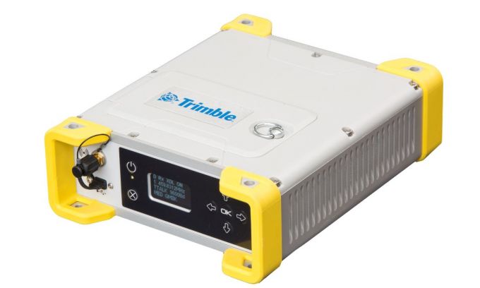
The MPS865 GNSS receiver is designed for marine positioning.
Trimble has debuted the MPS865 marine positioning system multi-frequency and multi-application GNSS receiver.
The Trimble MPS865 is a versatile, rugged and reliable GNSS positioning and heading solution for a wide variety of real-time and post-processing applications for marine survey and construction.
It features integrated communications options such as Wi-Fi, UHF radio, cellular modem for internet connectivity, Bluetooth and MSS satellite-based correction channels.
The patented GNSS-centric technology uses all available GNSS signals to deliver reliable positions in real time. The GNSS receiver provides for the connection of two GNSS antennas for precise heading.
With a modular form factor, the MPS865 is flexible and can be used as an integrated on-board rover receiver, a base station or a continuously operating reference station. According to Trimble, the built-in precise heading feature ensures the receiver is of minimal size, consumes less power and has less cabling, which are all benefits when on-board space it at a premium.
The MPS865 adds new features to improve usability in a congested marine construction site – multi constellations, cellular connectivity and beacon support. The multi-constellation option maintains productivity in marine sites or when antennas or satellites are partly obstructed.
At many sites, the receiver can use the free-to-air beacon support. When coupled with GA830 antennas, the MPS865 will receive the free-to-air beacon signals to deliver sub-meter accurate horizontal positioning in many parts of the world. It always delivers precise heading even when no GNSS corrections are received.
The marine receiver also has cellular, making it easier to use Internet Base Station Service (IBSS) and VRS corrections over the internet as well as communicate with the receiver via the internet and SMS messages. The receiver also can be used as a data access point on the vessel to download design files or for immediate remote support.
The MPS865’s design enables a broad range of mounting capabilities and built-in communication options. Features include an internal removable battery, internal memory and optional accessory kits for specific applications.
The receiver is also compatible with a variety of software solutions including the new Trimble Marine Construction software.
The weatherproof, high-impact-resistant moulded aluminium housing protects it in extreme marine conditions or base-station applications.
“With the addition of the MPS865 receiver to our portfolio, Trimble has introduced a new generation of rugged, compact and feature-rich GNSS, a solution the marine industry has been needing for some time,” said Scott Crozier, general manager of Trimble’s Civil Engineering & Construction Division. “This highly flexible and capable receiver can be combined with our marine construction software providing contractors with a market-leading solution for any marine survey or construction application.”
SenseFly is partnering with Trimble to optimize the drone mapping workflow for geospatial professionals.
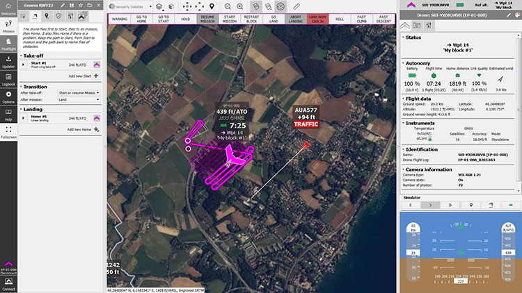
The new integration is designed to ensure a smooth end-to-end mapping drone workflow. senseFly operators can now, within the recently launched eMotion 3.5 software, transform a senseFly S.O.D.A. camera’s georeferenced imagery into an automatically collated project (in .jxl format).
This enables the one-click import of drone imagery into the Trimble Business Center Aerial Photogrammetry module without the need for manual project creation and organization of images.
The senseFly-to-Trimble mapping workflow includes:
planning and monitoring a senseFly S.O.D.A.-based drone flight (in eMotion 3.5)
downloading the drone’s images for one-click georeferencing in eMotion 3.5 (Flight Data Manager)
clicking to create a .jxl format mapping project
opening a project within the Trimble Business Center Aerial Photogrammetry module
processing the drone’s imagery to generate orthophotos, contour maps, point clouds, digital surface models (DSMs) and feature maps
analyzing and acting upon the data.
Screenshot: Trimble
“Making work easier and more efficient for geospatial professionals is the goal that drives every solution we develop,” said Jean-Christophe Zufferey, senseFly co-founder and CEO. “Therefore, we are excited to collaborate with Trimble on more tightly integrating our solutions, since enhancements such as this new eMotion-to-Trimble Business Center workflow do exactly that, ensuring that the transition from data collection to acting upon this data is as seamless as possible.”
The senseFly S.O.D.A. is built for professional drone photogrammetry work. The 1-inch, 20-megapixel RGB camera captures sharp aerial images across a range of light conditions, allowing senseFly fixed-wing drone operators to produce detailed, vivid orthomosaics and ultra-accurate 3D digital surface models.
senseFly S.O.D.A. is compatible with most senseFly fixed-wing mapping drones, including the large-coverage eBee Plus.
Trimble Business Center allows surveyors and other geospatial professionals to combine aerial photography with data collected from GNSS receivers, total stations, 3D laser scanners and more, for a complete field-to-finish workflow. By combining imagery from unmanned aerial systems with ground-based survey data, users can visualize their project from both aerial and terrestrial perspectives, measure points within the images and create 3D models of the infrastructure and terrain.
General Motors (GM) is using Trimble RTX (real-time eXtended) technology as the high-accuracy GNSS/GPS correction source to deliver absolute positioning to vehicles equipped with GM’s Super Cruise hands-free highway driving system, now available on the 2018 Cadillac CT6.
GM customers using Super Cruise featuring Trimble RTX technology can have peace of mind on the road knowing that RTX plays an important role in maintaining lane position for hands-free driving on divided highways.
https://youtu.be/_rxW68ADldI
Super Cruise also uses precision lidar mapping data, a state-of-the-art driver attention system, and a network of camera and radar sensors.
Trimble RTX technology provides real-time, multi-constellation GNSS positioning capable of achieving better than 1.5 inches accuracy. Standard GPS signals can drift up to 25 feet, which could cause incorrect lane identification.
The 2018 Cadillac CT6 features Super Cruise hands-free driving technology for the highway. (Photo: GM)
Lane-level accuracy is a critical enabler in advanced driver assistance systems increasingly being used on highways. When used in conjunction with high-definition maps, cameras, radar and inertial sensors, Trimble RTX improves lane-level positioning performance for semi-autonomous and autonomous vehicles.
Trimble has a long history of pioneering automation and vehicle autonomy to improve productivity — from providing positioning solutions for some of the earliest robotic applications in the 1990s to delivering automated steering for farm tractors, automated blade control for earthmoving equipment and providing advanced positioning technology for fully autonomous trucks.
Trimble is now enabling semi-autonomous operations for passenger vehicles with Trimble RTX technology, delivering high-accuracy GNSS corrections via a global network to support absolute vehicle positioning in combination with other sensors and inertial dead-reckoning.
Trimble’s RTX technology uses signals captured by more than 100 Trimble GNSS reference stations around the globe. Trimble RTX corrects the signals for atmospheric conditions, satellite orbit and time synchronization errors and then sends those signals to GM vehicles with Super Cruise via OnStar 4G LTE cellular.
The Trimble network is supported by redundant servers that are monitored 24/7 by a team of network engineers and IT specialists ensuring optimal signal performance and reliability for drivers who will depend on it.
“Through our collaboration, the combined technologies of GM and Trimble will transform the way the world drives,” said Patricia Boothe, vice president of Trimble’s Advanced Positioning Division. “Trimble RTX is now influencing how we interact with our vehicles and the environment around them — helping to minimize driver fatigue and improve the assisted driving experience.”
Trimble has acquired privately-held e-Builder, a software-as-a-service (SaaS)-based construction program management solution for capital program owners and program management firms.
e-Builder extends Trimble’s ability to accelerate industry transformation by providing an integrated project delivery solution for owners, program managers and contractors across the design, construct and operate lifecycle, the company said.
e-Builder manages more than $300 billion of construction project value and over 200,000 projects from some of the most influential owners in North America. Owners benefit from the e-Builder solution through improved transparency and accountability while contractors benefit from faster payments, increased productivity and improved competitive advantage.
The e-Builder solution is uniquely designed to measure and manage every step of the capital project delivery process including planning, design, procurement, construction and operations.
Trimble’s wide range of construction hardware and software solutions significantly improve project cost, schedule and effectiveness — beneficially impacting owners, architects, engineers and contractors. The Trimble presence in construction has two points of focus, one on civil engineering projects and the other on the construction of buildings and structures. Both will benefit from the e-Builder acquisition.
Trimble solutions leverage constructible building information model (BIM) workflows to integrate processes, improve information fidelity, reduce rework, establish transparency and deliver higher productivity. By using Trimble technologies, contractors and owners are realizing substantial reductions in total project cost.
The combination of Trimble and e-Builder accelerates value creation for both owners and contractors by combining e-Builder’s best practice solutions for owners with Trimble’s construction lifecycle solutions, access to contractors and global reach.
The combined solution portfolio will accelerate the integration of field operations with enterprise needs, enabling additional productivity gains. The tangible benefits include more consistent on-time and within-budget project delivery that is enabled by improved visibility, clear accountability for outcomes and the ability to convert large volumes of disparate data into actionable workflows and measurable outcomes.
“e-Builder has always recognized that owners play a key role in the construction lifecycle and that their influence will be key to the adoption of transformative construction technology,” said Steven Berglund, president and CEO of Trimble. “Trimble will extend its reach into the owner community by leveraging e-Builder’s presence. In turn, we intend to aggressively bring e-Builder solutions to civil and building contractors and the international market. We see a significant opportunity in leveraging data and intelligence gained through design-construct workflows across the full infrastructure lifecycle. e-Builder’s solutions and, more importantly, its organization provide a strong platform for significant growth.”
“e-Builder’s mission is to improve project execution to make construction faster, less expensive and more reliable,” said Ron Antevy, president and CEO of e-Builder. “The addition of our solutions to Trimble’s broad portfolio extends our collective ability to best support owners and contractors with project delivery and management. e-Builder current and future customers will benefit from Trimble’s construction management expertise, culture of innovation and global reach to take e-Builder solutions to the next level.”
The e-Builder business will be reported as part of the Buildings and Infrastructure Segment.
Financial Terms
The all cash purchase price of $500 million will be financed through a new $300 million credit facility and cash. The new facility has terms and conditions similar to the existing revolver with a 364 day term.
e-Builder’s reported trailing twelve month revenue is approximately $53 million. In recent years, e-Builder’s revenue growth rate has exceeded 20 percent annually, with greater than 65 percent subscription revenue as a percentage of total revenue. The transaction is expected to be dilutive to Trimble’s first quarter non-GAAP net income per share by $0.01 per share and dilutive to full year 2018 non-GAAP net income per share by $0.02 to $0.03 per share, due to the impact of fair value accounting of e-Builder’s deferred revenue and interest expense. Trimble expects the acquisition to be accretive to 2019 non-GAAP net income per share.
An overview of e-Builder and the strategic rationale for the acquisition is available on Trimble’s Investor Relations website. For a more detailed description of the acquisition and credit agreements see Trimble’s Form 8-K filed with the U.S. Securities and Exchange Commission (SEC) on Feb. 2, 2018.
About e-Builder
Founded in 1995, e-Builder is a provider of integrated, cloud-based construction program management software for top facility owners and the companies that act on their behalf.
The company’s flagship product, e-Builder Enterprise, improves capital project execution, resulting in increased productivity and quality, reduced cost and faster project delivery.
Since 1995, e-Builder’s technology leadership and construction industry focus have helped thousands of global companies, government agencies, and health care and educational institutions manage billions of dollars in capital programs with solutions to improve the plan, build and operate lifecycle.
The Trimble MX9 combines a vehicle-mounted mobile lidar system, multi-camera imaging and field software for efficient, precise and high-volume data capture for a broad range of mobile mapping applications such as road surveys, topographic mapping, 3D modeling and asset management.
The Trimble MX9 captures dense point-cloud data along with 360-degree immersive georeferenced imagery using a spherical camera, GNSS/INS technology and dual-head laser scanning sensors.
The system’s innovative and lightweight design facilitates easy installation and setup on a variety of vehicles. Spatial data can be captured at highway speeds from inside the vehicle for safe operation in transportation corridors.
The intuitive, browser-based field software, accessible via most tablets or any notebook, enables operators to quickly establish and conduct data-acquisition missions, monitor the status of the system, and assess the quality of the acquired data in real time.
“The Trimble MX9 is our next-generation mobile mapping system, focused on simple operation and integrated workflows for a new generation of users and applications,” said Ron Bisio, vice president of Trimble Geospatial. “We believe there’s a tremendous potential for a system that offers high-quality performance, simple installation and easy operation.
“Being able to capture high-fidelity and survey-grade data for a whole project site, a complete city or even a statewide road-network allows our customers to use mobile mapping data for a variety of surveying, engineering and mapping applications.”
The Trimble MX9 is designed for applications including transportation infrastructure planning, as-built surveying, GIS mapping and asset management. Survey and engineering professionals can analyze road cross-sections, perform clearance inspections, conduct topographic mapping, and also use the data for machine control.
Mapping professionals can utilize the same data for city mapping and planning, inventory mapping and 3D modeling of buildings and linework.
Complete integration with Trimble office software allows users to seamlessly process the acquired data and generate deliverables for a wide variety of applications. Tools are available for survey and engineering applications as well as deriving and publishing GIS and asset management deliverables.
Users can also easily export their data for use with third-party software.
The Trimble MX9 is available for virtual or live demonstrations, depending on customer location, beginning in April. The MX9 system includes a roof rack. Optional accessories such as a GNSS azimuth measurement system (GAMS) or a distance measurement instrument (DMI) are available.
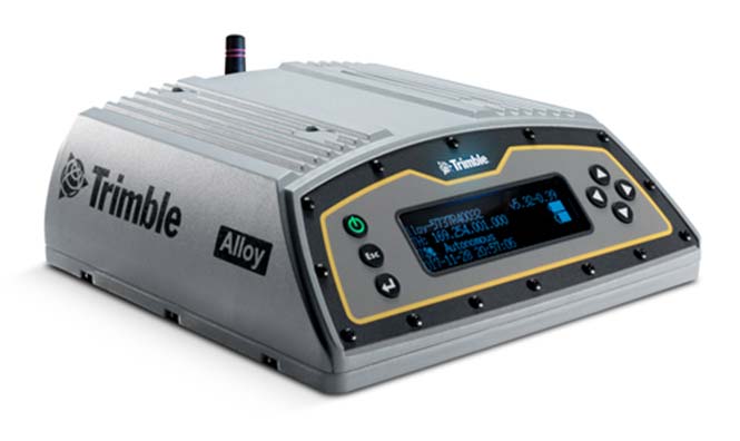
Trimble has introduced its next-generation GNSS reference receiver for real-time network (RTN) applications: the Trimble Alloy GNSS reference receiver.
With 672 channels, the continuously operating reference station (CORS) receiver provides users and operators with access to multiple constellations and signals, supplying robust and reliable reference data.
With an IP68 rating for protection against dust and moisture, the Trimble Alloy performs even in the most rugged environments to meet the demands of professionals from the earth science, surveying, construction, mapping and agricultural industries.
Delivering high-accuracy GNSS data to improve RTN performance and reliability, the Trimble Alloy GNSS receiver allows RTN owners and operators to:
Track and log all current and planned GNSS. Powered by the new Trimble Maxwell 7 GNSS dual chipsets, Trimble Alloy tracks and processes all of today’s current GNSS signals at data rates up to 100Hz, and is designed to be ready for planned signals and systems. The next generation receiver provides 672 channels for unrivaled GNSS constellation tracking including: GPS, GLONASS, BeiDou, Galileo, QZSS, IRNSS as well as the full range of SBAS.
Deliver absolute position monitoring. Leveraging Trimble RTX precise point positioning technology, the Trimble Alloy receiver is able to derive its position at centimeter-level accuracy in real-time. Combined with Trimble’s advanced Sentry monitoring technology, the receiver will automatically notify the operator of any status change including positional changes. The technology ensures users are receiving the most accurate correction data.
Realize new levels of user convenience. An all new intelligent receiver design brings an unprecedented level of usability to GNSS reference stations with the Trimble Alloy reference receiver. Featuring a tilted four-line OLED screen, Trimble Alloy displays key information without the need for scrolling through multiple menus. Dual hot swappable batteries, coupled with multiple power inputs, give users flexible installation options. Wi-Fi connectivity, multiple serial ports and remote access options allow users to configure the device easily, no matter how or where it’s installed.
“Alloy provides a solution to address a variety of installation challenges faced by RTN owners and operators today,” said Mark Richter, marketing director of Trimble’s Advanced Positioning Division. “The receiver can track all satellite signals at the highest possible data rate while being easy to use, access and configure. All of these features make the receiver a compelling investment for owner/operators who are looking to modernize their networks or single station configurations. Trimble Alloy will carry them far into the future.”
The Trimble Alloy GNSS reference station receiver is expected to be available in most of the world through Trimble’s Distribution Channel during the first quarter of 2018. For Asia and Latin America, the receiver is expected to be available in the second quarter of 2018.
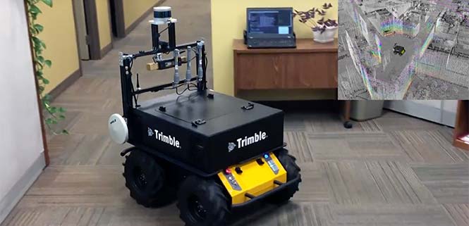
Applanix, a Trimble Company, has introduced its Autonomy Development Platform to provide automakers, truck makers and Tier 1 vehicle suppliers the hardware, software, engineering and integration services they need to accelerate their development programs for on-road and off-road autonomous vehicles.
By combining customized integration and engineering services along with Applanix’ GNSS-inertial positioning technologies, the Autonomy Development Platform advances driverless vehicle development projects at every stage of development and commercialization.
“With the introduction of our Autonomy Development Platform, Applanix now offers on-road and off-road vehicle manufacturers the tools and engineering expertise necessary to support and augment their driverless vehicle development programs,” said Louis Nastro, director of Land Products at Applanix.
“The platform delivers a navigation solution that is fully customizable and includes integration and engineering services, field-tested hardware and proprietary software for highly accurate positioning,” continued Nastro. “The navigation solution is capable of working with all sensors, including multiple cameras, lidar, radar and ultrasonic sensors, and with all vehicle types at all stages in the development and commercialization cycle.
“The Applanix technology enables highly accurate assessments of the full 360-degree environment around a vehicle to produce a robust representation, including static and dynamic objects, critical for successful vehicle autonomy.”
“Applanix has been committed to meeting the needs of autonomous vehicle manufacturers for more than a decade, going back to our success at the DARPA Challenges. In addition, our expertise in autonomous technologies is part of an extensive portfolio of Trimble solutions for automation and vehicle autonomy, which began more than three decades ago,” said Steve Woolven, president of Applanix. “Our refined positioning algorithms and expertise with sensor fusion and mobile robotic technologies enable us to provide a development platform that delivers the required performance and reliability for manufacturers to develop and produce self-driving vehicles for all environments and tasks.”
The Applanix Autonomy Development Platform is available now through the Applanix worldwide sales channel.
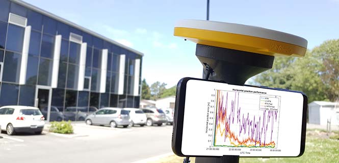
For those who want high accuracy, but don’t need it full time, high-productivity dedicated professional solutions may not be cost-justified. In these cases, a “positioning as a service” subscription could offer a viable use model.
Achieving precision positioning with just a standard mobile device, a correction stream using the mobile device’s data connection and a high-accuracy positioning application produces a very low barrier to achieving high accuracy.
ByStuart Riley, Herbert Landau, Victor Gomez, Nataliya Mishukova, Will Lentz and Adam Clare, Trimble Inc.
We expect that for professional applications that need precision positions, a dedicated system that employs a custom GNSS chipset and purpose-built applications will continue to be the right solution. However, it becomes clear that the ubiquity of consumer mobile devices, with increasing computing power, ruggedness and an expanding feature set, presents fertile ground for new development of improved positioning systems that don’t have strict professional requirements.
A range of new use models and applications will be enabled by consumer mobile phones with technology that improves positioning performance. The goal of the work presented here is to assess what level of performance can be achieved by using proprietary PVT (position, velocity, time) engines utilizing GNSS measurements from the Android GNSS measurement application programming interface (API).
We first review GNSS measurement and positioning performance from a subset of the current Android phones/tablets currently on the market. Then we show the position performance achievable using precision engine with measurements from a dual-frequency GNSS chipset targeted for the cellular handset market. This class of device is expected to be integrated into consumer cellular devices on the market within the next 1 to 2 years.
Performance of Current Phones
We tested various devices including the Nexus 9 (which provides phase data) and various other Android devices that implement the new API. Most devices tested do not support phase data; of the few devices tested that do provide phase data, all except the Nexus 9 implement GNSS power duty cycling. This is a mode where the GNSS chipset is only active for a fraction of each second to reduce power consumption. This results in cycle slips each epoch, which makes carrier-phase processing for real-time kinematic (RTK) unusable.
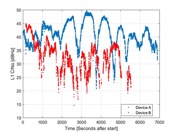
During the testing a wide range of performance across devices was observed. Figure 1 shows the C/NO for a high-elevation GPS satellite collected at the same time from two different Android models that implement the GNSS measurement API. The units were located in a clear environment less than a meter apart. Deep fades are present, most likely caused by deconstructive multipath.
Figure 1. Comparison of the C/NO from two different Android devices.
However, the devices show significantly different tracking performance: device B reports over 10 dB lower C/NO for much of the test and eventually stops reporting measurements. During our analysis, around six different Android devices have been tested; it isn’t clear whether the devices tested are typical over a broader population of device types.
Before attempting to position with observables from Android devices the measurement quality was analyzed. As only a subset of current devices that support the API provide phase information we wanted to evaluate both a phase-based RTK engine and a pseudorange/Doppler based code engine to determine what is possible from each class of device.
One of the devices tested was a Samsung S7 device. It provides pseudorange, Doppler and phase via the GNSS measurement API. However, the phone implements power duty cycling so after a short period of operation the duty cycling mode was enabled which resulted in a cycle slip on the phase every epoch.
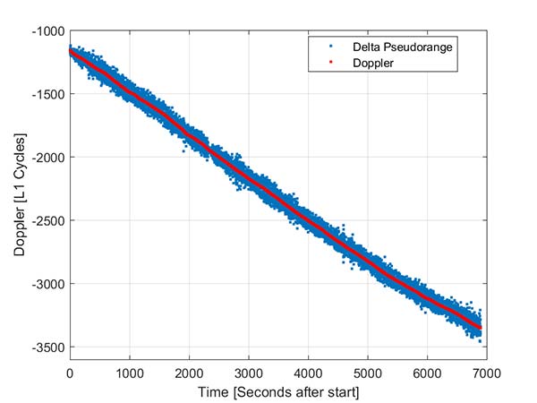
To derive an improved position from this class of device pseudorange and Doppler can be fed into a code-phase positioning engine. Fortunately, the Doppler provided by the device is of reasonable quality as can be seen from Figure 2.
Figure 2. Android GNSS observables: Doppler versus time-differenced pseudorange.
In this simple analysis measurements from a single high elevation satellite were analyzed. The Doppler is plotted along with the differenced pseudorange converted into L1 cycles. It can be seen that as expected the Doppler has much lower noise and so can be used in a pseudorange smoother.
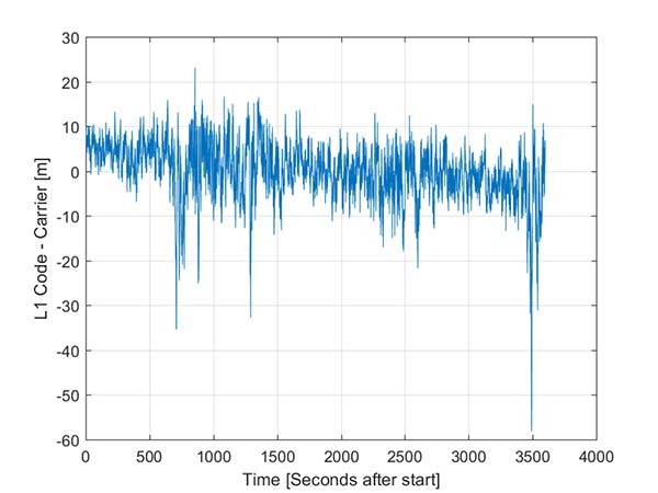
A simple way to view the pseudorange noise is to subtract the carrier phase from the pseudorange. If there are no cycle slips this should show ionospheric divergence with the noise dominated by the pseudorange noise. The absolute level is arbitrary as it includes integer carrier cycles. Figure 3 shows an example from an Android device.
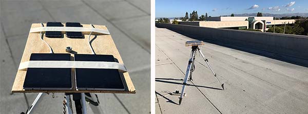
The data was captured on a building roof in an open environment. There’s a slight downward trend due to the ionospheric divergence between code and carrier, but the metric is dominated by the pseudorange noise. For this example from a high elevation GPS satellite the standard deviation is 6.5 meters. For comparison, a precision receiver connected to a precision GNSS antenna providing unsmoothed pseudorange in this environment would have a standard deviation of a few decimeters.
Another way to assess the measurement performance is to form double difference residuals. Data was logged from pairs of identical devices mounted with a common orientation. An RTK system was used to measure the same point on each device. The camera lens location above the screen was used as the reference point.
An accurate vector between the two references points was computed and used as truth in a double-difference residual analysis. Even though we do not know the precise location of the phase center of the antenna, because the difference was performed between two devices that are the same model and have the same orientation the error in the phase center location is common and will cancel. Various pairs of devices were tested by being mounted on a wooden board on a tripod at approximately waist height. The test configuration is shown in Figure 4.
Figure 4. Android device test configuration.
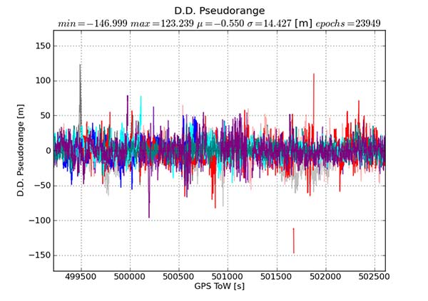
Figure 5 provides the double difference GPS L1 C/A pseudorange residuals between two Android devices. We see errors beyond 100 meters and a standard deviation across all data of 14.4 meters. A precision system (RTK or RTX/PPP) would use a standard survey quality base or network of bases and not an Android device for the correction data.
Figure 5. Short baseline double-difference pseudorange, Android devices.
Consequently in a typical operating mode where a precision data stream provides corrections, the contribution in a double difference from the pseudorange on the Android devices would be roughly half the Android-to-Android residual seen in this test or approximately 7.2 meters for this example.
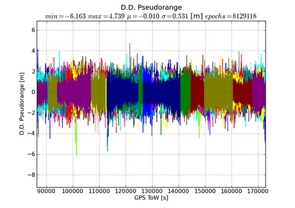
For comparison, the same metric was generated between two precision GNSS units connected to antennas on the same roof. While the data was not from the same time period, we observe very consistent performance over time.
Figure 6 shows the same pseudorange double difference across a short baseline over 24 hours. When comparing Figures 5 and 6, note the difference in the scale on the pseudorange residual axis. The standard deviation from a pair of precision devices is 53 centimeters (cm) or 27 times lower noise than an example pair of Android devices.
Figure 6. Short baseline double-difference pseudorange, precision devices.
All phones that provide GNSS measurements via the Android API publish the phase data in the accumulated delta range field. An accumulated delta range is not necessarily a full phase measurement; it can have an arbitrary starting phase.
For example, in a precision GNSS receiver, if the receiver locks to a satellite and some time later locks a second channel to the same satellite, the phase measurement from the two channels may have a different integer cycle component, but the subcycle component would be the same except for millimetric tracking noise.
If the two channels are providing accumulated delta range the initial phase offset may differ by up to one cycle. From the population of Android devices that publish phase that we have tested we have not observed any devices that deliver true full phase.
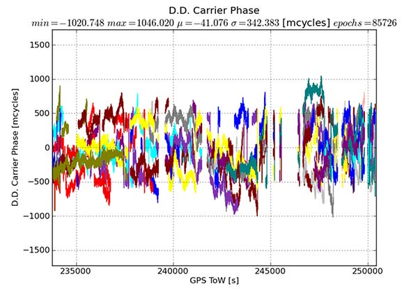
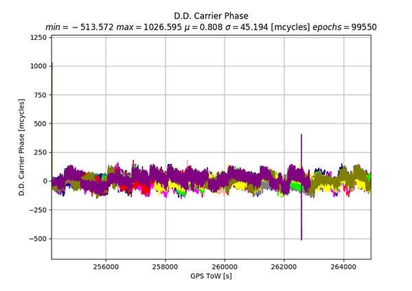
They all deliver an accumulated delta range with an arbitrary phase offset. This limits a phase engine to float processing and ambiguity fixing is not possible. The Android phase data collected from the previously described experiment was processed to provide the double difference carrier residuals. This is shown in Figure 7.
Figure 7. Short baseline double-difference phase residuals, Android devices.
The y-axis is in millicycles (1,000 millicycles = 1 cycle or approximately 19 cm for L1 GPS). Jumps are seen as the reference satellite changes or when the measurements have cycle slips. In this case the standard deviation is 342 millicycles. A double difference residual on a precision receiver in a similar environment with a high-quality antenna on a short baseline is an order of magnitude lower than this.
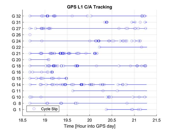
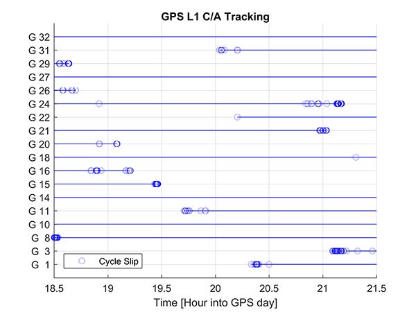
Another useful metric to review are the number of reported cycle slips. Figures 8 and 9 show a comparison of the cycle slips reported on GPS L1 C/A from an Android device compared to data logged on a precision receiver over the same time span. The receiver tends to only cycle slip at low elevation; the device had a zero-degree mask. The Android GNSS device cycle slips at higher elevations, probably a result of deep multipath fades due to the poorer antenna.
In an ION GNSS+ 2017 paper, we showed the achievable position performance using an RTK engine that had been previously customized to operate with measurements from consumer GNSS chipsets. It operated in a float mode due to the sub-cycle issue found in phase data from Android devices.
We also demonstrated the performance from a precision code-based PVT engine that had changes to the a priori measurement error estimate, a modified pseudorange/Doppler Hatch filter and used SBAS data to correct the position. As very few current Android devices deliver phase information the two engines were used to analyze what is possible today with the pseudorange and may be available in the future as phase is more universally available.
Data was processed from a Nexus 9 tablet, the only known Android device that has GNSS power duty cycling disabled. The unit was unmodified and so the Android tablet’s integrated GNSS antennas were used. The 2D performance is given in Table 1.
Table 1. 2D performance from Nexus 9 Android tablet.
Only GPS L1 and GLONASS L1 measurements were used and the RTK float solution delivered similar performance to the pseudorange solution. This is due to a combination of issues, very high pseudorange noise, and a significant number of cycle slips (see Figures 5 and 8). Only single frequency data was available, and while the engines used had been tuned for consumer data, they were not specifically designed for this class of data.
Next-Generation Phones
Within the next couple of years improved chipsets are expected to be available to consumers that will result in improvements in achievable positioning performance. In May 2017, Broadcom provided us with a development kit for its next generation L1/L5 multi-system BCM47755 GNSS chipset. This allowed us to assess what may be possible when improved GNSS chipsets are integrated in the next generation of cellular devices.
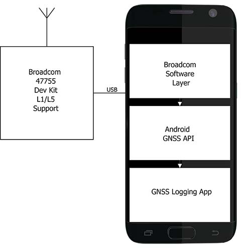
Figure 10. Broadcom BCM47755 development system.
The development environment included the GNSS chipset with an external antenna port so both a cell-phone equivalent antenna and a precision antenna could be compared. This allowed us to evaluate the impact of the antenna performance on the GNSS observables and positioning results. The Broadcom GNSS development system communicates via USB to a Samsung S7 phone and publishes data via the Android GNSS measurement API so the equivalent data flow of an integrated cellular device is maintained (see Figure 10).
In our ION paper, we showed the typical phase double-difference residuals observed from current Android devices. The Broadcom BCM47755 originally provided similar performance, although it also supports GPS L5 and Galileo E5A. In November 2017, Broadcom provided a firmware update that resolved the sub-cycle phase issues. With the updated Broadcom software, the double difference carrier residuals for GPS L1 on a zero baseline when differencing a precision receiver to a Broadcom BCM47755 are shown in Figure 11.
Figure 11. Precision GNSS to Broadcom BCM47755 zero baseline double difference carrier-phase residuals.
The standard deviation is 45 millicycles which is approximately 8.6 millimeters (mm). This is substantially better than earlier implementations of the Android GNSS interface (see Figure 7) and sufficient to perform RTK ambiguity resolution.
The rest of the results in this article were obtained with the improved firmware along with a new precision position engine. This engine was designed from inception to support GNSS measurements with differing quality and so can more optimally process the Android GNSS data. The effect of the improvements to the Broadcom firmware and the change in the processing engine can be seen if the results in our ION paper are compared to the data in this section.
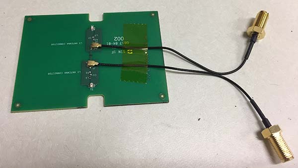
To attempt to model what may be possible with a phone based on a next-generation chipset, a cell-phone equivalent antenna provided by Broadcom was used in some of the tests with the development system, as shown in Figure 12. This device has separate feeds for L1 and L5.
Figure 12. Cellular equivalent antenna.
Datasets were collected with the multi-frequency GNSS BCM47755 device. The data was captured in the Android GNSS measurement API format and converted to proprietary format files for further processing. All data was collected in Sunnyvale, California.
Measurements from GPS L1/L5, Galileo L1/E5A, GLONASS L1 and BeiDou B1 were logged and analyzed. The Precise Positioning Engine (PPE) allows performing carrier-phase RTX and RTK and a pseudorange-based solution using the RTX corrections. Tests were performed by using a precision antenna and a cell-phone equivalent GNSS antenna.
With Precision GNSS Antenna
These datasets were collected on a zero baseline with a precision receiver to allow a direct comparison of results with a professional receiver. The first test was on Nov. 22, 2017, where the Broadcom GNSS chip and the receiver were connected to the same professional antenna.
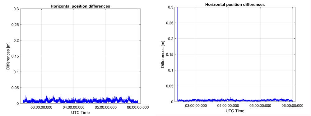
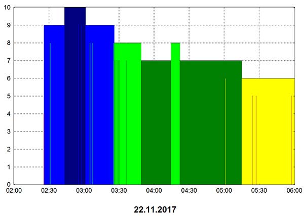
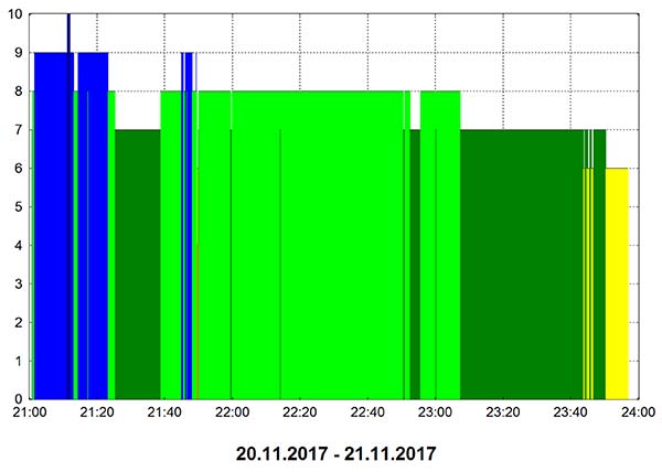
As seen in Figure 13, both GNSS receivers provide centimeter-level accuracies after some convergence time. With the current satellite constellations, only a third of the GPS satellites have L5 and only about half of the E5-capable Galileo constellation is in space. During this 3.5-hour test, the number of dual-frequency measurements processed by the engine that used the Broadcom chipset — data that does not support L2 — ranged between 6 and 10 satellites (Figure 14).
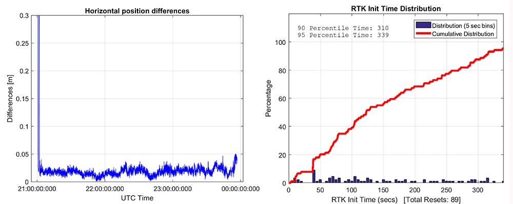
Figure 13. RTK performance for a 3.5-hour dataset sampled on Nov 22. Broadcom chip at left and precision chip at right. A short baseline was used — precision antenna.Figure 14. Number of GPS L1/L5 plus Galileo E1/E5A dual-frequency measurements used by the position solution based on the Broadcom chipset — precision antenna.
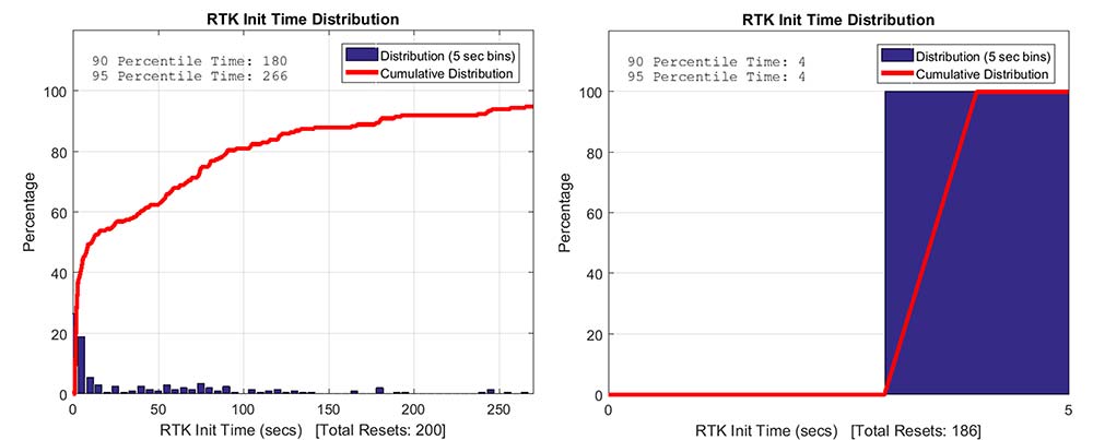
Convergence times were measured with post-processing tools by splitting the datasets into individual time spans. Figure 15 shows that the consumer GNSS chipset is able to get fixed ambiguity solutions but it takes considerably more time (266 seconds versus 4 seconds) for the 95% of initializations. However, the system is fixing ambiguities and provides centimeter level positioning.
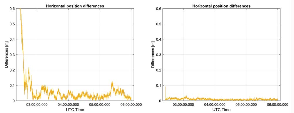
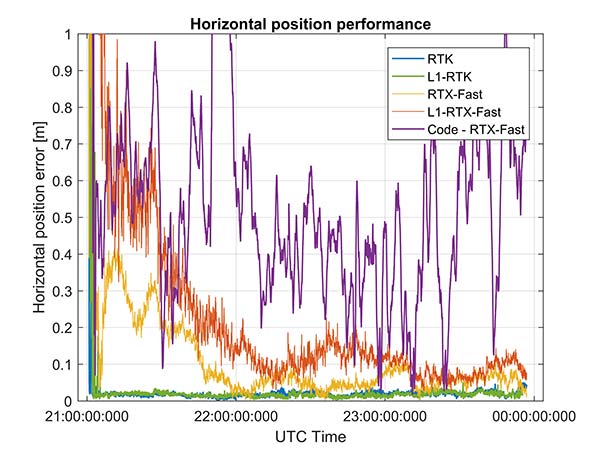
The same datasets were also processed with RTX-Fast in California. Thus the base station data was replaced by a global/regional correction stream received from an internet-based data source (Figure 16).
Figure 15. RTK initialization performance, dataset sampled on Nov 22. Broadcom chip at left and precision receiver at right — precision antenna.Figure 16. RTX performance for a 3.5 hour dataset sampled on Nov. 22 (Broadcom chip at left and Trimble chip at right) — precision antenna.
Horizontal accuracy for Broadcom reach 10 cm while the precision receiver reaches better than 3 cm. The degradation is in part due to the difference in quality of the carrier phase and the different number of dual frequency satellites processed. Precision devices provide measurements on E1/L1, L2 and L5/E5 providing at least dual frequency data from GPS, GLONASS, Galileo, BeiDou and QZSS.
The Broadcom chipset tested provided dual frequency GPS and Galileo along with single-frequency GLONASS and BeiDou; however, due to limited BeiDou constellation visible in California, data from this constellation was not used.
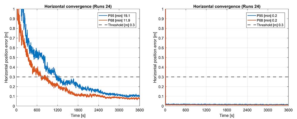
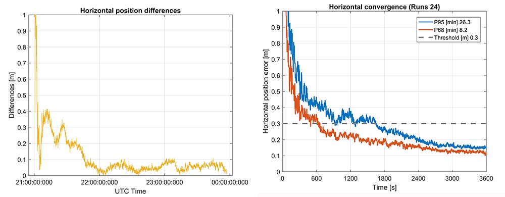
Convergence was also analyzed and is shown in Figure 17. From the data, we generated 24 convergence runs by taking one hour, progressively shifting the start time by 5 minutes and running the data with different start times through the PPE engine. This produced 24 runs, which were translated into 68% and 95% convergence statics shown.
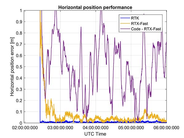
Figure 17. RTX convergence performance for a 3.5-hour dataset sampled on Nov. 22. Broadcom chip at left and precision chip at right — precision antenna.Figure 18. Code RTX performance for 3.5-hour dataset sampled Nov. 22 and corresponding RTK and RTX phase solutions — precision antenna.
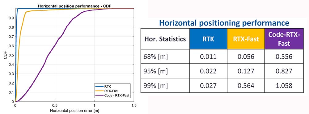
The RTX-Fast solution for Broadcom reaches 30 cm horizontal error in 68% of the cases in approximately 12 minutes. The RTX-Fast convergence using precision GNSS data is near instantaneous as can be seen in the right of Figures 16 and 17, reaching centimeter accuracy.
The code position solution using the RTX correction stream provides sub-meter positioning (Figure 18).
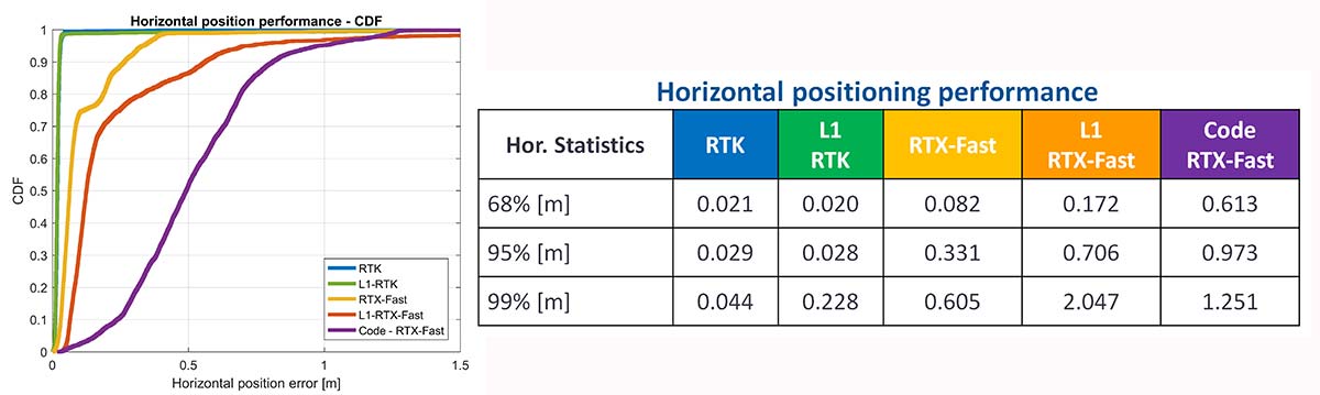
As a summary, the cumulative distribution function plots (Figure 19) show the performance differences for this static environment, on Nov. 22.
Figure 19. CDF plots for the different PPE position solutions — precision antenna.
Cell-Phone GNSS Antenna Results
Similar tests were performed using an external cell-phone GNSS antenna, which is close to the antenna used in a typical smartphone. RTK performance shows centimeter-level accuracies and reasonable convergence times, which are slightly worse than the results with the professional antenna (Figures 20–24).
Figure 20. RTK positioning and initialization performance for the Broadcom chip and the cell antenna sampled on Nov 20 — cell-phone GNSS antenna.Figure 21. RTX-Fast positioning and convergence performance for the Broadcom chip and the cell antenna sampled on Nov. 20 — cell-phone GNSS antenna.
In general as expected we achieve worse performance when connected to the GNSS cell-phone antenna for all the different positioning modes. For the cell antenna we also generated single-frequency RTK and single-frequency RTX-Fast position solutions and compare it with a code positioning solution.
Positioning Engine in Android
Figure 22. Number of GPS L1/L5 plus Galileo E1/E5A dual-frequency measurements used by the position solution based on the Broadcom chipset — cell-phone GNSS antenna.
The results presented in this article captured GNSS data using the Android API and then post-processed the data using PC versions of the position engines. A significant amount of data has been captured and analyzed using this method.
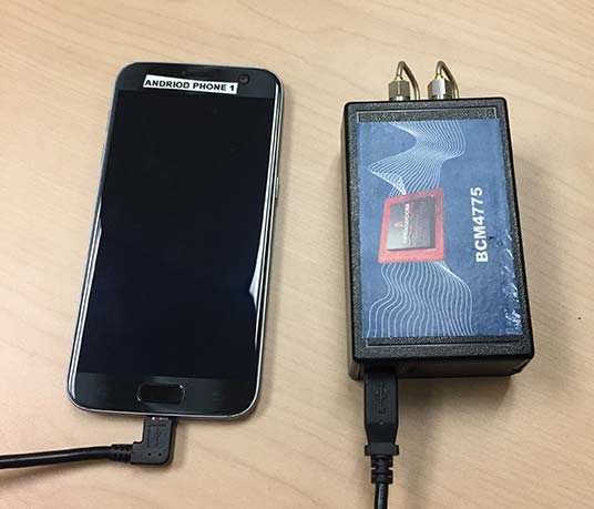
For the purpose of real-world demonstration the PPE has been implemented in an Android app to be used in cell phone devices. This PPE is able to provide RTK, RTX and code based positioning technology in one single PPE library.
The app has been tested running on a Samsung S7 connected to Broadcom’s new chipset development kit as well as a Nexus 9 tablet that uses an older generation GNSS chipset.
Figure 23. Code RTX performance, the dataset sampled Nov. 20 and corresponding RTK and RTX phase solutions — cell-phone GNSS antenna.
Future work will refine this solution as well as evaluate how well the system works when mobile. The data collected in this article operated in an environment with a clear view of the sky. We plan to characterize what happens when the platform moves with both pedestrian and automotive dynamics, as well as the effects of body masking and challenges with changes to the GNSS antenna reception pattern when the phone is held.
Summary
While this article has highlighted that sub-meter and centimeter accuracy have been achieved in a laboratory environment, there are many challenges to be addressed before centimeter accuracy in a phone can be achieved with performance suitable for users in real-world environments.
Figure 24. CDF plots for the different PPE position solutions for cell antenna dataset.
The challenges include very high multipath, significant differences in the tracking performance between different devices, and high rates of cycle slips. As very few Android-based devices provide continuous phase, a pseudorange/Doppler-based engine has been modified to accept Android data.
Based on the testing with existing devices it is possible to achieve position solutions of 1–2-meter accuracy in ideal static scenarios. This is a significant improvement in accuracy for Android based devices.
Figure 25. PPE engine on a Samsung S7 with a Broadcom BCM4775 evaluation kit.
However, as performance differences were observed between different mobile devices significantly more data needs to be collected over a larger set of devices to review the repeatability of these preliminary results from existing Android devices.
The Broadcom BCM47755 development kit for a dual-frequency GNSS chipset intended for future phones has allowed us to review the potential position performance that may be achievable in a handset in a few years.
By connecting this next-generation GNSS chipset to a GNSS antenna typical of a cellular device and comparing the performance from a precision GNSS antenna, we’ve shown for the first time that it is possible to produce precision positions from a static cellular class GNSS device in ideal conditions at the centimeter level with both an RTK solution and a PPP solution.
However, due to the significantly higher measurement noise and high multipath from the cellular device’s GNSS antenna, the convergence times to reach centimeter level remain a challenge; although using dual-frequency phase data from a cellular GNSS chipset with a PPE and RTX service, the position is very rapidly sub-meter.
Future work will focus on analyzing how the performance changes when operating in the normal user environment. The effects on the measurements of user motion, body masking and de-tuning of the antenna when the device is held need to be quantified. The Nexus 9 tablet used in this article does not have integrated cellular. The Broadcom development kit connects to the phone via a cable and is also not integrated into the handset.
We will be evaluating what may happen with a more integrated unit to make sure emissions from devices with integrated cellular very close to the GNSS antenna do not result in further degradation.
As the position performance is very sensitive to the quality of the antenna from both multipath and cycle slips due to low C/NO and deep fades, we’ll also evaluate how well the performance of the PCB-based GNSS antenna, which is part of the BCM47755 evaluation kit, matches current handsets.
Acknowledgment
This article further develops work first shown in an ION GNSS+ 2017 paper, “On the Path to Precision — Observations with Android GNSS Observables.”
Manufacturers
Trimble CenterPoint RTX is the satellite orbit and clock corrections service used here, enabling a PPP-like positioning with ambiguity fixing, providing better than 4 cm with typically less than 10 minutes’ convergence.
RTX-Fast functionality in Europe and parts of California uses regional atmospheric models to provide better than 4-cm horizontal in typically less than one minute. When precision and professional receivers and RTK engines are mentioned in this article, they are Trimble devices, the BD940 receiver in some cases.
A Trimble Zephyr 3 antenna was used in many tests shown here.
The global market for precision agriculture solutions is forecast to grow from €2.2 billion ($2.6 billion) in 2016 at a compound annual growth rate (CAGR) of 13.6 percent to reach about €4.2 billion ($5 billion) in 2021, according to a research report from the market analyst firm Berg Insight.
A set of technologies are applied in precision farming practices that are aimed at managing variations in the field to maximize yield, raise productivity and reduce consumption of agricultural inputs. While solutions such as auto-guidance and machine monitoring and control via onboard displays are mainstream technologies in the agricultural industry, telematics and variable rate technology (VRT) are still in the early stages of adoption.
Interoperability between hardware and software solutions remains a challenge, although standardization initiatives led by organizations such as Agricultural Industry Electronics Foundation and AgGateway are making progress.
Most major agricultural equipment manufacturers have initiatives related to precision agriculture, although strategies vary markedly. Leading vendors include agricultural equipment manufacturer Deere & Company, followed by the U.S.-based precision technology vendors Trimble, Topcon Positioning Systems, Raven Industries and Ag Leader Technology. Hexagon further holds a strong position in the positioning segment through its subsidiary NovAtel.
A group of companies have emerged as leaders in the nascent market for in-field sensor systems. These include Davis Instruments, Pessl Instruments with its METOS brand, Semios, Hortau, AquaSpy and CropX.
The Think 3D Stormbee multicopter integrated with Trimble’s AP15 provides efficiency, accuracy and performance for lidar surveys from unmanned vehicles.
Historically, lidar-based aerial surveys were impractical for all but the largest unmanned systems. Because of Applanix’ development of small, lightweight and low-powered direct georeferencing solutions, airborne lidar scans from small drones are now practical, cost-effective, highly accurate and excellent options for lidar surveys, according to the company.
The Stormbee is a directly georeferenced UAV lidar solution for 3D industrial mapping applications, designed to collect survey grade spatial data in a significantly more cost effective and efficient way than static lidar.
The Stormbee, a Faro Focus 130 laser scanner, and the AP15.
Stormbee’s 3D mapping technologies include Faro’s Focus 130 laser scanner, Trimble’s AP15 high performance GNSS/inertial receiver, Applanix’s POSPac UAV GNSS/inertial post-processing software and Stormbee’s proprietary Beeflex software for lidar point cloud generation.
Industrial applications (GNSS-denied environments) pose unique challenges for laser scanning using traditional static systems, due to obstructions and poor signal environments. These issues lead to increased costs and operational time.
By using the high-performance Trimble AP15 with two antenna and the Applanix post-processing software (POSPac MMS) for georeferencing the lidar data, Stormbee provides an accurate real-time and post-mission solution for all motion variables.
Applanix has brought together its decades of experience in multi-frequency, multi-constellation Differential GNSS and inertial based positioning and orientation with the best in small-form factor hardware and powerful software, to produce a DG solution for professional aerial mapping on UAVs.
With a system delivering better than 5-cm accuracy (real mean squared) and high resolution, Stormbee and Applanix offer 3D detail from a platform moving at speeds up to 15 meters per second. The Stormbee leverages Applanix’s decades of experience in direct georeferencing of lidar systems to collect the most accurate 3D data.
Benefits of the system:
compact, easy-to-operate and cost-effective
centimeter-level mobile positioning accuracy for 3D mapping products
improved productivity, with optimized workflow from data capture to georeferenced point cloud generation
superior visualization: Lidar scanners provide more accurate information of structures than camera technologies
Think 3D, a Belgian company, is a 3D scanning company for many industrial applications including those in the beverage, steel, pharmaceuticals, chemicals and tank terminals industries. Think3D helps companies make changes to their installations by providing a full 3D CAD model of their installation.
Stormbee to date has proven to be effective in many industries including mining, engineering, dredging, forensics, universities and survey.
RTX Fast reduces the convergence time — the duration needed to reach full precision accuracy — by up to 98 percent faster than other satellite-delivered correction services, Trimble said.
The service allows customers to realize horizontal positioning accuracy of better than 4 centimeters (1.5 inches) in as fast as one minute. With RTX Fast, farmers, surveyors, geographic information system (GIS) professionals and construction contractors can work faster, improve productivity, minimize input costs and reduce worker fatigue, Trimble added.
New RTX Fast services have recently launched in Switzerland, Slovakia, Northern Italy, Eastern Poland and the Southern regions of Saskatchewan and Manitoba.
In addition, Trimble has a 60 percent larger footprint in the Central U.S., including new coverage in Kentucky and Tennessee.
As the requirement for real-time, absolute positioning grows, Trimble is expanding its RTX Fast coverage to meet the demand both geographically and for the markets it serves, including new emerging applications in vehicle autonomy and location-based services.
The demand for real-time absolute positioning in driving applications continues to rise as Advanced Driver Assistance Systems mature and accuracy requirements become more stringent. RTX Fast provides the network enhancement necessary to deliver fast, high-accuracy RTX corrections for real-time positioning while on the road.
“Trimble RTX technology has been adding value to our core markets since its introduction in 2011. And, now we are demonstrating its capability in new applications such as autonomous driving solutions,” said Patricia Boothe, vice president of Trimble’s Advanced Positioning Division. “We are committed to expanding the reach, use and accessibility of Trimble RTX technology, reinforcing its position as a leading solution for improving GNSS performance.”
Trimble’s GFX-750 display system was designed to provide farmers with more robust signal availability.
Trimble launched the GFX-750 display system for agriculture applications. According to the company, the display system comes with a simple-to-install, roof-mounted NAV-900 guidance controller featuring its most advanced multi-constellation GNSS receiver.
The GFX-750 features a high-resolution 10.1-inch display, which is ISOBUS-compatible, a universal communication protocol that Müller-Elektronik, a Trimble company, helped develop. ISOBUS allows one display or terminal to control several implements and machines, regardless of manufacturer, the company said. The display system runs on Trimble’s high-performance Precision-IQ software.
In addition, the GFX-750 offers flexible connectivity between devices through Bluetooth, WiFi and BroadR-Reach and communication from tractor to farm equipment. It has the ability to connect to signal corrections, including CenterPoint RTK, CenterPoint VRS, Trimble RTX technology and SBAS through the NAV-900 controller. The system is also compatible with Trimble Autopilot and interoperable with Trimble Ag Software.
“The GFX-750 display system is the perfect solution for a farmer who is ready to get started with precision farming—or who is interested in upgrading to a new system—due to the easy-to-use interface and roof-mounted guidance controller with embedded GNSS receiver,” said Abe Hughes, general manager at Trimble’s Agriculture Division. “This comprehensive display system can enable farmers to more easily adopt precision agriculture solutions across their farm, regardless of vehicle make, model or year.”
The GFX-750 display system comes with a triple-frequency multi-constellation GNSS receiver from Trimble that uses GPS, GLONASS, Galileo and BeiDou satellites, the company added.