Artist’s impression of the CACI/York Space DemoSat scheduled to launch in January 2023. (Credit: CACI)
CACI International, a U.S. defense contractor, plans to demonstrate a supporting navigation technology for military use as part of its DemoSat launch in January 2023.
CACI will launch two demonstration payloads on a York Space Systems satellite scheduled to fly to low Earth orbit in January aboard the SpaceX Transporter 7 rideshare.
The payload will contain an alternative positioning, navigation and timing solution that will work in a contested space domain. It is designed to support rather than replace GPS.
The technology is two-way time transfer and clock modeling technology. Two-way time transfer has been used for years on the ground, but in this case will be used in space. The low size, weight and power (SWaP) space-based PNT is expected to significantly improve multi-platform remote sensing.
If the experiment is successful, CACI plans to offer the two-way time transfer PNT service to the military and other government agencies.
CACI has completed the critical design review for the DemoSat. CACI and its partner York Space Systems will also demonstrate a tactical intelligence, surveillance and reconnaissance (TacISR) payload. The TacISR payload identifies and captures key signals of interest and operates with CACI’s Beast ground receiver to demonstrate real-time radiofrequency geolocation for deployed U.S. forces.
“CACI expertise, systems, and technology help our customers maintain dominance in the increasingly contested space environment,” said Mike Hale, executive vice president of CACI’s Advanced Solutions Group. “We are very proud that CACI is launching a DemoSat payload into orbit – distinguishing our mission technology and transformative solutions for customer success.”
Tersus GNSS has released a white paper on ExtremeRTK Technology. According to the company, the white paper demonstrates how ExtremeRTK Technology delivers excellent performance in all manner of surveying scenarios and describes its impressive compensated results when performing tilt surveys — even tilt at angles greater than 90°.
As a professional real-time kinematic (RTK) developer and manufacturer, Tersus believes the stability and accuracy of RTK are the cornerstones of RTK measurement.
According to the paper, “ExtremeRTK integrates the receiver’s hardware, high-precision baseband IC [integrated circuit], RTK engine, GNSS/INS coupling algorithm, etc. It enables unprecedented performance stability in challenging environments and prevents occurrences of occasional RTK positioning outliers.”
Tersus starts from scratch — engineering each element from its foundation in the physics of GNSS. From signal capture and baseband tracking engine to position-velocity-time (PVT) results and the overall algorithm of RTK, Tersus completes all algorithm logic independently.
The white paper discusses:
signal tracking and multipath mitigation capabilities
fix speed in open-sky and challenging environments
accuracy when performing RTK control/detail point/continuous point surveys
GNSS/INS tilt compensation.
Test results described indicate the remarkable performance of ExtremeRTK technology in RTK initialization, accuracy and tilt compensation. Based on ExtremeRTK, Tersus will continue to invest in the further development of RTK receivers by adding photogrammetry, laser scanning and more.
Meanwhile, Tersus will also focus research and development on professional industry software, the integration of resources in data management, and big-data applications so it can provide users with additional professional services.
Hexagon | NovAtel’s GAJT-710ML installed on a U.S. Army vehicle. Photo: U.S. Army Futures Command
We asked Dean Kemp, Ph.D., director of Marketing, Aerospace and Defense for Hexagon’s Autonomy & Positioning division, a few questions.
How do jamming and spoofing threats change?
Jamming and spoofing methods change as new interference-causing technologies become available. As such, it’s vital for us to continuously evaluate potential sources of threats and provide the highest possible level of resiliency to interference in our solutions.
Have new threats emerged in the past six weeks in connection with Russia’s invasion of Ukraine?
Evidence is emerging that electronic-warfare systems capable of high-power jamming and spoofing across wide areas are being used within Ukraine. Fortunately, there have been no known impacts on allied forces. However, knowing that the technology is in place and in use highlights the importance of assured positioning, navigation and timing (APNT) and our contribution to building resiliency in allied forces’ equipment against the potentially destabilizing effects of jamming and spoofing.
How do you define APNT?
We use APNT to describe measurements that are always accurate, available and reliable. Our anti-jamming, anti-spoofing and other resilience-building capabilities provide trusted and available PNT information at the level of accuracy requested.
When did you introduce GPS Anti-Jam Technology (GAJT)? How do you define it?
GAJT was introduced in 2011 and is our leading APNT solution. GAJT units are utilized worldwide across land, sea and air, with rapid deployment supported by commercial off-the-shelf solutions and short lead times. GAJT provides jamming protection of satellite-based navigation and precise timing receivers from intentional jamming and unintentional interference whatever your application. Product variants provide features to best support anti-jamming capabilities for the warfighter, national infrastructure, low-SWaP platforms and other mission-critical applications.
What are the key differences between the GAJT-710ML, the GAJT-710MS and the GAJT-410MS?
The GAJT-710 is designed for land vehicles (ML variant) and marine vessel platforms (MS variant) with up to six simultaneous nulls to protect against jamming signals and interference. The next generation of GAJT-710 includes jammer direction-finding and a silent mode to reduce its thermal signature. The GAJT-410 maintains the high levels of interference-rejection performance in the 710 but in a lower size, weight and power (SWaP) design, with three simultaneous nulls, for both land and marine variants. It also utilizes a single RF cable to provide clean power, data and protected GPS signal. The GAJT-410 enables APNT while also reducing the need for platform modifications or armor penetration.
The GAJT-AE extends jamming and interference protection to unmanned and autonomous applications. Using an external CRPA antenna, the GAJT-AE offers flexibility of integration into space-constrained platforms.
Is the GAJT-AE-N Anti-Jam Antenna receiver-agnostic?
We designed our GAJT product line to be receiver-agnostic and compatible with legacy and modern GNSS receivers. This flexibility results in GAJT being ideal for civil and military applications, including SAASM and M-code systems.
How does your GNSS Resilience and Integrity Technology (GRIT, launched in 2020 November) relate to your GAJT antennas?
GRIT is a firmware suite for our OEM7 receivers that expands their situational awareness and interference mitigation tools. GRIT includes our Interference Toolkit (ITK) along with spoofing detection to identify when your GNSS signal may be under threat. It also empowers the user to develop interference location algorithms through time-tagged snapshots of data samples to characterize the RF environment around your operations. GRIT, alongside GAJT, forms the foundation of our APNT strategy in providing accurate and always-available PNT.
Do you have any recent contracts with the U.S. Department of Defense or the militaries of other NATO countries to supply GAJT antennas?
Our GAJT product portfolio has been sold in large quantities to military and civil organizations for many years, successfully proving itself in the field. In 2020, we achieved a milestone of more than several thousand units shipped worldwide, making it one of Hexagon | NovAtel’s more successful years.
Chip-scale atomic clocks can supplement GNSS receivers to provide accurate and reliable time in GNSS-challenged environments. Photo: Microchip Technology
Accurate and reliable time is just as important as accurate and reliable location for a wide range of military and civilian applications — and GNSS receivers cannot provide either one when they are jammed. For timing, one solution is to supplement GNSS receivers with a miniature atomic clock. We asked Microchip Technology a few questions about their chip-scale atomic clock (CSAC) and Stewart Hampton, the company’s senior product line manager, responded.
How long was your SA65 CSAC in development before you announced it in August 2021? Typically, how often do you launch a new CSAC?
CSAC development started in 2001 under a contract from DARPA with Draper and Sandia laboratories. CSAC was first introduced to the commercial marketplace in 2011, and in 2016 we released an improved product design with an operating temperature range of –10 C° to +70 C°. Last year we released our CSAC SA65 with a wider operating temperature range, faster warm-up and improved frequency stability aimed at the defense and industrial marketplace. So, it has been about five years between major CSAC releases, but that may not be indicative of future products because we have also introduced specialized CSAC versions, such as the Low Noise CSAC (LNCSAC) in 2014 and the only commercially available radiation-tolerant CSAC (Space CSAC) in 2018.
What is the CSAC SA65’s drift rate?
Its typical drift rate is specified at <9 × 10⁻¹⁰ per month. Another key specification, particularly for many portable military applications, is total sensitivity of frequency to temperature (tempco) over a specified range. For the CSAC SA65, that specification is ±3 × 10⁻¹⁰ over the entire operating temperature range of –40 C° to +80 C °.
What are a few specific military use cases?
CSAC is designed into multiple military programs and used in a wide variety of military applications, particularly in GNSS-denied environments — including assured positioning, navigation and timing (APNT) modules, underwater unmanned and autonomous vehicles, software-defined radios, man-portable transceiver-based military communications, vehicle management computers, airborne reconnaissance/UAVs and GNSS-disciplined oscillators. It is also used in command, control, communications, computers, cyber, intelligence, surveillance and reconnaissance (C5ISR). The space CSAC variant is commonly used on low-Earth-orbit space defense payloads supporting such applications as low-latency communications networks, RF geolocation (geointelligence, or GEOINT), optical time transfer, alternative PNT satellites and Earth observation.
Spirent Federal Systems, a PNT simulation company, offers its government customers and contractors a unique solution for anechoic-chamber-based CRPA testing: a patented “zoned chamber” approach using multi-output, multi-constellation GNSS signal simulators to emulate the movement of satellites in orbit.
To address the limits of a standard anechoic chamber, Spirent has created independent zones configured to represent the real-world sky view, using genuine constellations and improved satellite azimuth and elevation arrival angles. Test scenarios can be multi-constellation and multi-frequency with customizable time, date and duration — now lasting hours instead of minutes.
Because scenarios are valid for longer time periods without sacrificing realism, the zoned chamber is effective for validating all aspects of the CRPA system including beamforming, null steering and space-frequency adaptive processing/space-time adaptive processing (SFAP/STAP). CRPA systems with inertial sensors can be tested with static and dynamic scenarios using a positioner within the chamber.
Additionally, to account for multipath and signal obscuration, Spirent has integrated a 3D environment modeling tool which generates all the variables of a multipath-rich environment in real time, including ground reflection. Interference sources such as jammers and spoofers can be added anywhere in the chamber and concurrently simulated with the GNSS signals. Authorized users can also test classified RF signals such as MNSA M-code and Y-code.
“Spirent Federal’s goal is to get new technologies to U.S. warfighters at a speed that outpaces near-peer threats,” said Jeff Martin, vice president of Sales. “The realism of our patented zoned chamber allows advanced CRPA systems to be deployed faster with confidence they will perform in GPS-contested environments.”
Illustration of a simulated test environment incorporating GNSS, multipath and jamming in a Spirent zoned chamber. (Image: Spirent Federal)
BAE Systems has produced more than one and a half million military GPS receivers. The company is transitioning receiver designs to use the modernized military code (M-code) signal for added resiliency in RF-challenged environments. We asked Luke Bishop, director and product line engineering lead for the company’s Navigation & Sensor Systems, a few questions.
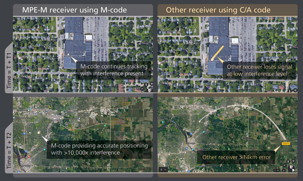
BAE Systems’ MPE-M provides the benefit of M-Code operation in a challenged RF environment. Image: BAE Systems
Why transition to M-code?
There are three key reasons for users to transition to M-code as supported by Military GPS User Equipment (MGUE). First, MGUE provide U.S. forces and our allies with enhanced PNT capabilities while improving resistance to threats, such as accidental and intentional jamming. Compared to the current P(Y)-code signal specs, M-code signals are stronger. Second, MGUE provides improved resistance to spoofing. Third, MGUE is field programmable, enabling updates to accommodate future enhancements to the GPS enterprise, such as regional military protection (RMP).
Which user equipment is transitioning to M-code?
Successful MGUE Inc 1 prototype development is being leveraged into a full portfolio of weapons, ground and aviation/maritime M-code GPS receivers. Our first production M-code receiver, MPE-M, achieved production deliveries in CY2021, with more than 1,000 delivered. Additional M-code GPS form factors are under development.
We are also underway with the Foreign Military Sales (FMS) M-code program with MPE-M.
How is the transition to M-code proceeding?
As indicated by the January 2021 GAO report (GAO-21-145), M-code-capable user equipment is in the initial stages of Department of Defense (DOD) fielding for select weapon systems. Also noted by the GAO report, the DOD has conducted bulk purchases of the Increment 1 ASICs [application-specific integrated circuits] to ensure that “sufficient supplies of [them] are on hand for future integration into M-code card …based on estimated need through 2028.” We are at the beginning of M-code (MGUE). Time and the market will tell what ultimately happens.
Which of your receivers operate with an anti-jam (AJ) antenna?
BAE Systems’ receivers support both stand-alone AJ and integrated AJ. Receivers with integrated AJ include the NavFire-M, NavStorm-M and SABR-M receivers supporting high-dynamic weapons applications. Receivers directly supporting external AJ via a digital beamforming interface include the MPE-M and AMR. Our external AJ DIGAR offering provides exceptional performance for many stakeholders.
Do you use advanced signal simulation equipment?
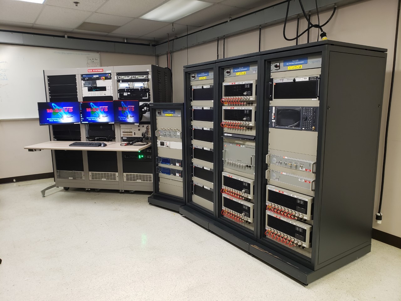
We integrate Spirent Federal and other signal simulators in both our test and development environments, where modeled RF signals are coordinated with other sensor measurements and host vehicle messages for high-fidelity hardware-in-the-loop test cases. Our engineers create hundreds of test cases and scripted test procedures to exercise our products under all required conditions. These simulations allow us to run thousands of trials to qualify and validate performance of our products in extreme scenarios.
BAE Systems’ hardware-in-the-loop simulation environments build upon Spirent Federal signal generators to test products under extreme dynamic and threat environments. (Photo: Spirent Federal)
Leonardo DRS’ A-PNT Converged Computer – Embedded & Scalable (AC²ES) adds capabilities to its widely used DDUx. Photo: Leonardo DRS
To help counter attacks that degrade GNSS capability on combat vehicles, Leonardo DRS developed a modified data-distribution unit computer, the DDUx II, with an embedded assured positioning, navigation and timing (APNT) capability the company calls Assured Positioning, Navigation and Timing Converged Computer Embedded & Scalable (AC²ES). It augments standard military GPS PNT sources with technologies such as anti-jam, anti-spoof, M-code receivers, additional RF sources, vehicle infrared (IR) sensor vision navigation, wheel rotation and inertial measurement units (IMUs). It also offers a choice of multiple timing holdup modules that increase accuracy proportionately with cost.
The DDUx II and military variants, fielded by the U.S. Army and Marine Corps, allow for integration of APNT functionality with the Battle Management System (BMS). It can provide APNT distribution to all other devices needing PNT within the vehicle without adding to its size, weight and power (SWAP).
Following a five-year development program, Leonardo DRS launched the AC²ES in September 2021 as a commercial option while continuing discussions with the U.S. Army and Marine Corps, which have not yet adopted it. “We have tested it,” said Mike Stucki, business development manager for the company’s land electronics division. “We have gone to Army jamming and testing events. We have performance and results. However, it has not been officially tested under the Army or Marines programs, with which we are moving forward this year.”
Leonardo DRS wants to offer the armed services the additional components they need to achieve APNT “and not require them to buy anything they don’t need or want,” Stucki said. Those additional components include multiple GNSS receivers for timing and a low-end internal IMU to provide continuous navigation in case GNSS is disrupted. All these components fit directly into the existing DRS hardware. Under the Mounted Family of Computer Systems (MFoCS) program alone, the Army has fielded more than 100,000 DDUx units. Some vehicles already have high-end INS, wheel encoders, and other sensors, and MFoCS can ingest their data.
Navigating with Infrared
For vision navigation, Leonardo DRS uses software developed by its partner Leidos that ingests data from existing hardware on the vehicles, many of which already have IR cameras. In a GNSS-denied environment, this enables the system to navigate by matching what the IR camera sees to an imagery database. Leidos’ software is based on work it began in 2011 with the DARPA All-Source Positioning and Navigation (ASPN) program.
“Leidos developed algorithms that use these other sensor inputs in the sensor-fusion engine to provide more accurate absolute positioning in a completely RF-denied environment,” said Kevin Betts, PNT director for Leidos. “We take the live images from the vehicle’s existing IR camera and match them to a satellite-derived model of the environment. When the images match, we have an absolute position update that we can provide to the navigation filter.”
MFoCS “is the heart that runs the Blue Force tracker system that the soldiers use,” said Bart Blanchard, director of advanced programs at Leonardo DRS. “We’ve added the APNT components inside that box. They’re leveraging the hardware that they already own. It’s a very cost-effective solution.”
Better Performance Combining Fiber Optics and Wideband Radio
Innovation Insights with Richard Langley
“OH DEAR! OH DEAR! I SHALL BE LATE!” That’s what the White Rabbit said in the opening chapter of Lewis Carroll’s Alice’s Adventures in Wonderland just before checking the time on its pocket watch. Scientists at the European Organization for Nuclear Research (known by its French acronym CERN) named their project to develop an Ethernet-based network for general purpose data transfer and sub-nanosecond accuracy time transfer after the time-conscious rabbit. CERN’s White Rabbit (WR) can provide sub-nanosecond accuracy to synchronize more than 1,000 nodes via optical fiber or copper connections of up to 100s of kilometers in length. It is a flexible system with a scalable and modular infrastructure with a simple configuration and low maintenance requirements. It is also open source.
WR uses the IEEE 1588 Precision Time Protocol (PTP) to establish precise phase differences between a master reference clock and a local clock. A two-way exchange of PTP synchronization messages allows precise adjustment of clock phase and offset.
So, what has this got to do with GPS or more generally GNSS? Well, for one thing, a WR-based system can serve as a back-up for GNSS time transfer or even replace GNSS. For example, a multi-hop WR link has been installed to connect financial trading locations in Chicago and New Jersey over an approximately 1,350-kilometer distance. Stock markets and other financial institutions need to time-tag transactions with traceable synchronization to a high-accuracy time standard to the microsecond level or better and a WR link can easily provide that.
Another application of WR is in terrestrial positioning. As we know, one of the problems with GNSS positioning is its poorer performance in built-up areas compared to open ones due to blocked signals and multipath. Multipath signals from close-by reflectors can be particularly pernicious as they reduce pseudorange measurement accuracy and thereby increase position error. And another potential weakness of GNSS is its susceptibility to radio-frequency interference, jamming and spoofing. A positioning system using synchronized roadside radio transmitters could be a viable alternative to GNSS in urban areas. A team of researchers based in The Netherlands has developed just such a system. In this month’s column, they describe their system, which uses WR to synchronize the transmissions of wideband radio ranging signals, and how they are able to achieve decimeter-level position accuracy in multipath environments.
By Cherif Diouf, Han Dun, Gerard Janssen, Erik Dierikx, Jeroen Koelemeij and Christian Tiberius
GPS is undoubtedly the most popular system providing positioning, navigation and timing (PNT) services to a host of applications, industries and infrastructures. GPS is mass-adopted, has worldwide coverage, has an impressive up-time and can be used with a wide range of receiver devices, featuring low to high cost and low to high precision.
Despite its strengths, the system also has some weaknesses. For instance, the positioning performance provided by GPS in dense multipath environments, such as in urban canyons, is poor. This is due to the interaction between the desired line-of-sight (LOS) component and close-in multipath components of the GPS signal reflected or scattered by built-up surroundings. Moreover, GPS signals, due to their low received power levels, are fairly vulnerable to unintentional and intentional threats such as radio-frequency interference, jamming and spoofing.
Alternative solutions that may complement or back up GPS, and more generally any other GNSS, to achieve reliable PNT for critical services and infrastructure, such as first responders, telecommunication and power systems, are urgently sought after. Wide coverage area synchronization using White Rabbit optical fiber networks allows simultaneous Ethernet networking and dissemination of 100 picosecond-level accurate time and frequency signals over distances of hundreds of kilometers. Accurate time synchronization may be provided to large areas such as big cities through this technology.
Building on such an accurate system, we present a concept and demonstration of an innovative hybrid optical-wireless terrestrial networked positioning system (TNPS). The TNPS demonstrator uses a White Rabbit infrastructure to accurately synchronize the transmissions of wideband radio positioning signals by its ground-based transmitters (pseudolites) and achieves decimeter-level positioning accuracy in an urban road-like configuration.
SCALABLE FIBER NETWORK DISTRIBUTION
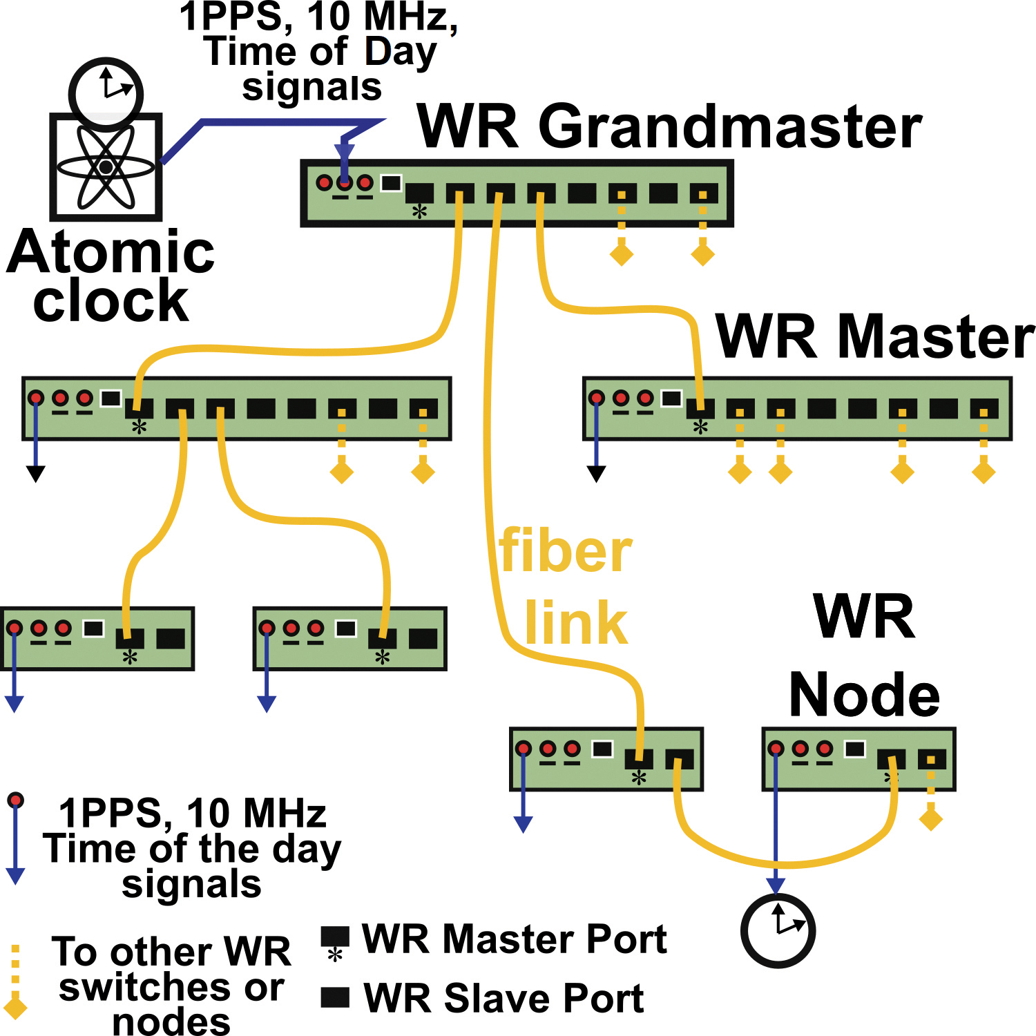
Initially developed for the Large Hadron Collider at the European Organization for Nuclear Research (CERN), White Rabbit (WR) is an accurate and scalable fiber-optic time and frequency transfer method that allows for dissemination of time references at sub-nanosecond level over distances of hundreds of kilometers. A typical WR network layout is shown in FIGURE 1.
FIGURE 1. Simplified topology of a White Rabbit (WR) network for optical time and frequency distribution. The yellow lines represent fiber-optic connections and the blue lines are electrical connections.
A central atomic clock provides synchronization references to a principal WR master switch dubbed the “grandmaster.” The grandmaster feeds synchronization signals into the network. which is expanded via fiber-connected WR devices: the switches and nodes of the network. These devices are serially linked to each other following a hierarchical master-slave pair configuration.
Accurate synchronization between a master and a slave WR-pair is performed as follows. The pair, which is connected via a bidirectional 1.25 gigabits per second optical Ethernet data link, quasi-continuously measures the round-trip delay of the data signals exchanged between the two devices. From these round-trip measurements, the one-way propagation delay, assumed symmetrical, is derived and compensated by the WR devices through an electronic control loop. To take into account possible asymmetries within a link, a calibration procedure is needed when initially installing the connection between a master and a slave. In practice, within smaller scale networks, the synchronization offset accuracy between devices is at the 100 picosecond-level. A 400-picosecond offset between WR devices has even been demonstrated over a distance of 169 kilometers, and more recently over a distance of 800 kilometers.
Besides the fiber-optic connection with other elements of the WR network, each switch or node can share its time-frequency references to an external device or system. These time-frequency references are available either in the form of IEEE 1588 Precision Time Protocol time stamps (via Ethernet connection), or in the form of electrical 1 pulse per second / 10 MHz synchronization signals (via coaxial cables).
THE CONCEPT
Centimeter- or even decimeter-level positioning accuracy is challenging to achieve using GNSS. In dense multipath environments, such as in urban canyons or indoor locations, the accuracy provided by GNSS is poor compared to the meter-level accuracy achievable in open terrain with the Standard Positioning Service. Moreover, GNSS services are vulnerable to interference, spoofing and jamming, and may be denied in indoor areas. We propose a TNPS based on a WR synchronization infrastructure as a complement to GNSS, providing higher timing and positioning accuracy, which also works in challenging environments.
TNPS can achieve decimeter-level accuracy in challenging environments through the use of wideband radio positioning signals. The attainable ranging precision is inversely proportional to the signal bandwidth. Furthermore, in dense multipath environments such as urban canyons, using wider bandwidth signals allows for finer time resolution. As a consequence, close-in received multipath components (MPCs) can be better resolved, and the LOS component can be more easily discriminated from delayed MPCs. This results in more accurate position solutions.
TNPS DEMONSTRATOR
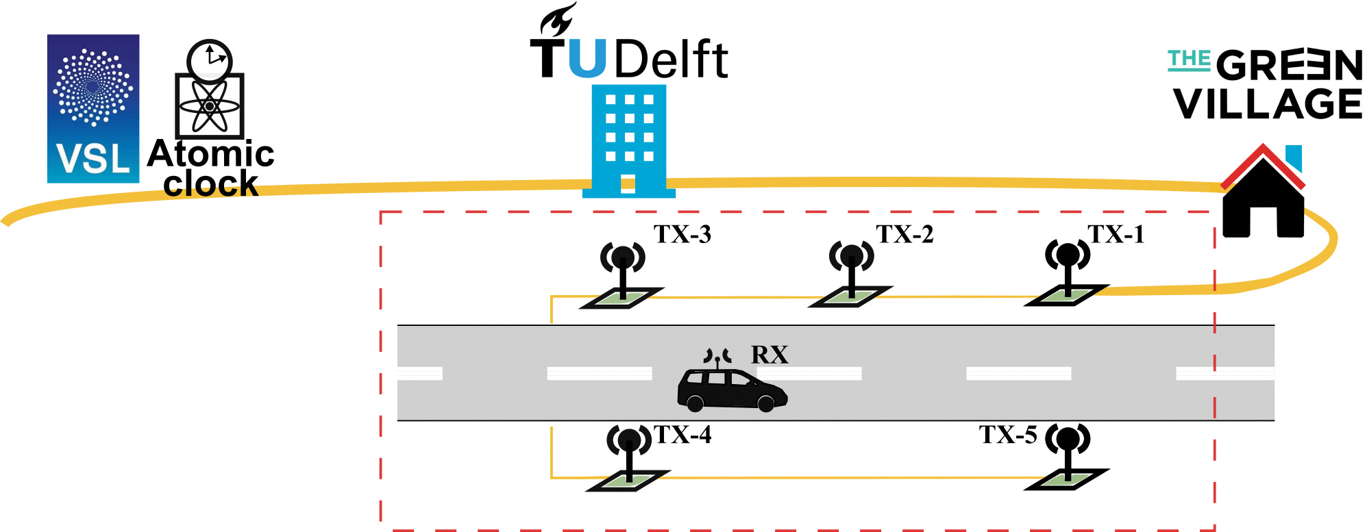
We performed a demonstration of the concept in Delft, The Netherlands, at The Green Village (TGV), an experimental facility on the campus of the Delft University of Technology. The facility aims to accelerate development and implementation of innovations for a sustainable future (see FIGURE 2).
FIGURE 2. Implementation of the TNPS demonstrator. The time-frequency reference is provided by VSL and forwarded to TU Delft via optical fiber (in yellow) and distributed through the optical WR synchronization infrastructure. Wireless radio transmitters (green squares) connected to the WR network deliver wideband ranging signals to perform terrestrial positioning and navigation.
The central synchronization reference of the TNPS demonstrator is the Dutch national timescale version of Coordinated Universal Time UTC(VSL), derived from atomic clocks at the Van Swinden Laboratory (VSL), the Dutch metrology institute. The UTC(VSL) 10 MHz frequency reference and 1 pulse per second time reference are fed to the WR grandmaster switch (WR-SW1). The grandmaster switch is subsequently connected to a distant WR switch (WR-SW2) through a 1,470-nanometer downstream and a 1,490-nanometer upstream 1.25 gigabit per second optical link. WR-SW2, located at one of the TU Delft data centers, synchronizes in turn a WR node (WR-N1) installed at TGV.
The remaining TNPS nodes at TGV are synchronized through a daisy-chain configuration. The first node (WR-N1) is connected to a second one (WR-N2), which is then connected to a third (WR-N3) and so on. In total, five timing nodes, WR-N1 to WR-N5, are connected to one another, using 50-meter optical fibers. These 5 timing nodes are used for synchronization (see FIGURE 3), and provide 1 pulse per second and 10 MHz electrical signals to five wideband radio transmitting units, uTX-1 to uTX-5, installed along a 50-meter stretch of road at TGV.
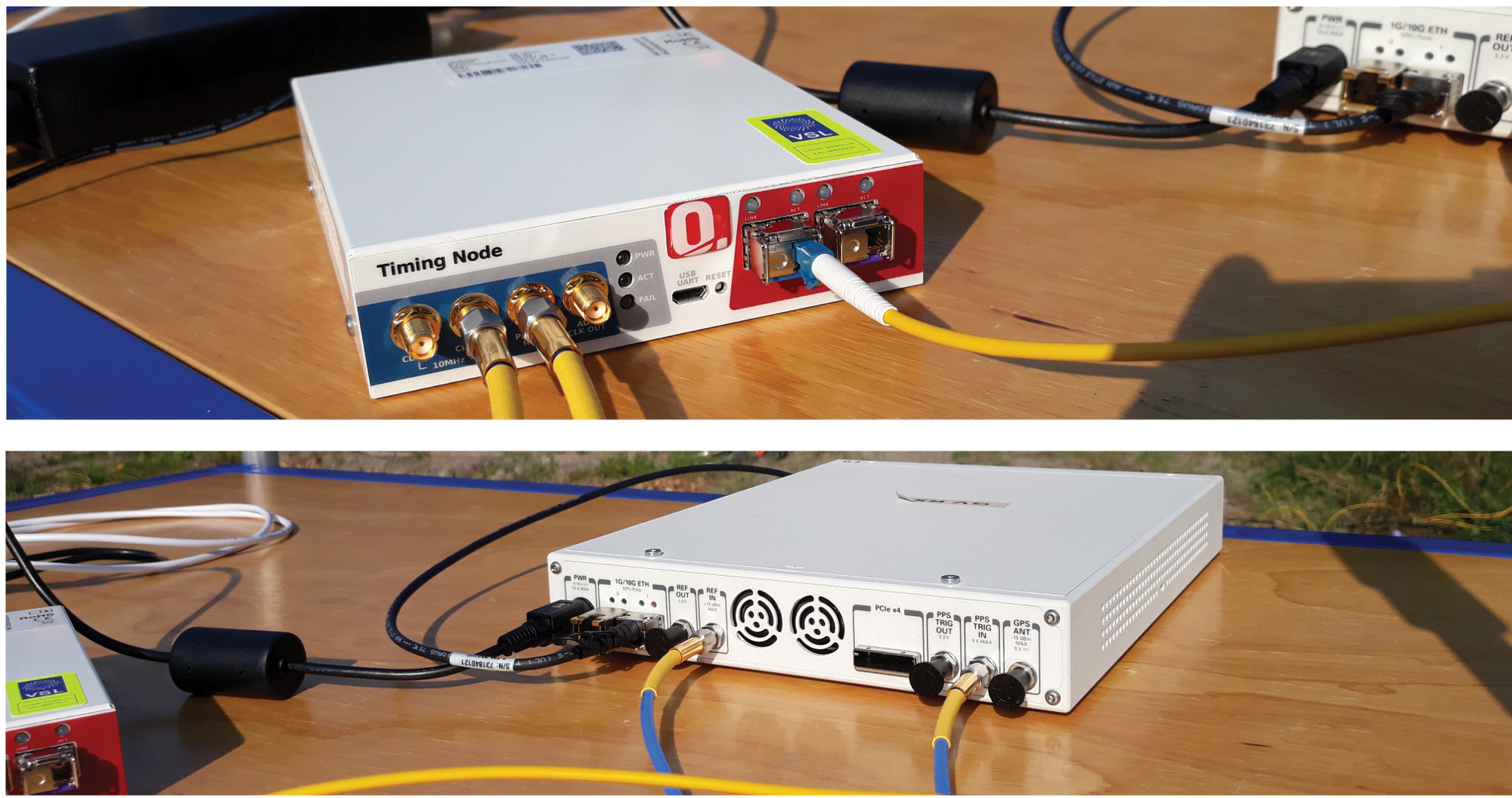
FIGURE 3. WR timing node (top) fed by a 1.25 gigabit per second bitstream through an optical fiber (yellow cable to the right) and providing electrical 1 pulse per second and 10 MHz synchronization signals at the outputs (two cables to the left). The bottom image shows an SDR system. The two channels of this device, capable of wideband operation, act here as a wireless transmitter or as a receiver. The transmitters are synchronized to the WR network through the 1 pulse per second and the 10 MHz electrical signals (blue-yellow cables at bottom) provided by the WR timing node.
A transmitting unit is based on a wideband transceiver: a software-defined radio (SDR) system linked to a wideband antenna that can operate from 700 MHz to 6 GHz. The antennas are connected to the SDRs using coaxial cables with a length of 5 meters and mounted on lampposts along the road at a height of about 4 meters. The transmitting units, uTX-1 to uTX-5, are respectively associated with antennas TX-1 to TX-5.
Each of these SDRs is capable of transmitting a wireless signal of up to 160 MHz bandwidth, on one or two of the device transmitter channels. The central frequency of each channel is tunable from 10 MHz to 6 GHz. In the demonstrator, we used a 3.96 GHz carrier frequency. The transmitting units periodically stream 160 MHz wideband quadrature phase-shift keying (QPSK) modulated pseudorandom noise (PRN) ranging signals sampled at 200 MHz. The five transmitters operate according to a time-division-multiplexing (TDM) scheme; uTX-1 to uTX-5 successively transmit the QPSK-modulated sequences as a 27.5-microsecond “burst” before turning idle. Between two successive transmissions, a guard interval of 3 microseconds is inserted during which all transmitting units are in idle state. It takes in total 150 microseconds for the five units to complete a transmission round, after which the units remain idle. The transmission round is then retriggered each millisecond.
At the receiver side (RX), another SDR platform is configured to acquire the QPSK modulated bursts transmitted by the five units uTX-1 to uTX-5. This SDR is actually playing the role of a data acquisition platform, which records and forwards the incoming sampled ranging sequences to the host PC via an Ethernet link. All processing and analysis in the demonstrator is performed offline, rather than in real time, using the collected ranging signals. The sampling rate of the acquisition platform is 200 MHz. A sample consists of a 16-bit in-phase value and a 16-bit quadrature-phase value (4 bytes in memory). In continuous operation, the SDR acquisition throughput would amount to 800 megabytes per second.
A throughput of 800 megabytes per second is difficult to handle for most of the host PCs. The SDR is therefore configured to only forward the relevant part of the data collected. Only the received samples time-aligned with the 150-microsecond transmitting window are periodically transferred to the host PC at a rate of 1 kHz. In practice, the acquisition window is slightly extended to 160 microseconds. Overall, the data throughput between the SDR and the host PC is now reduced to 128 megabytes per second; that is, 10 seconds of acquisition will generate a data file of 1.28 gigabytes.
A Schmidl & Cox synchronization sequence is embedded in the signal transmitted by uTX-1. The SDR field-programmable gate array continuously performs autocorrelation on the incoming samples and uses this sequence to detect the arrival time of the ranging bursts for operation in asynchronous mode. The receiver also can be operated in synchronous mode, that is, synchronized to a timing node.
TEST SETUP
We carried out experiments on a 50-meter-long and 6-meter-wide local road at The Green Village (see FIGURE 4).
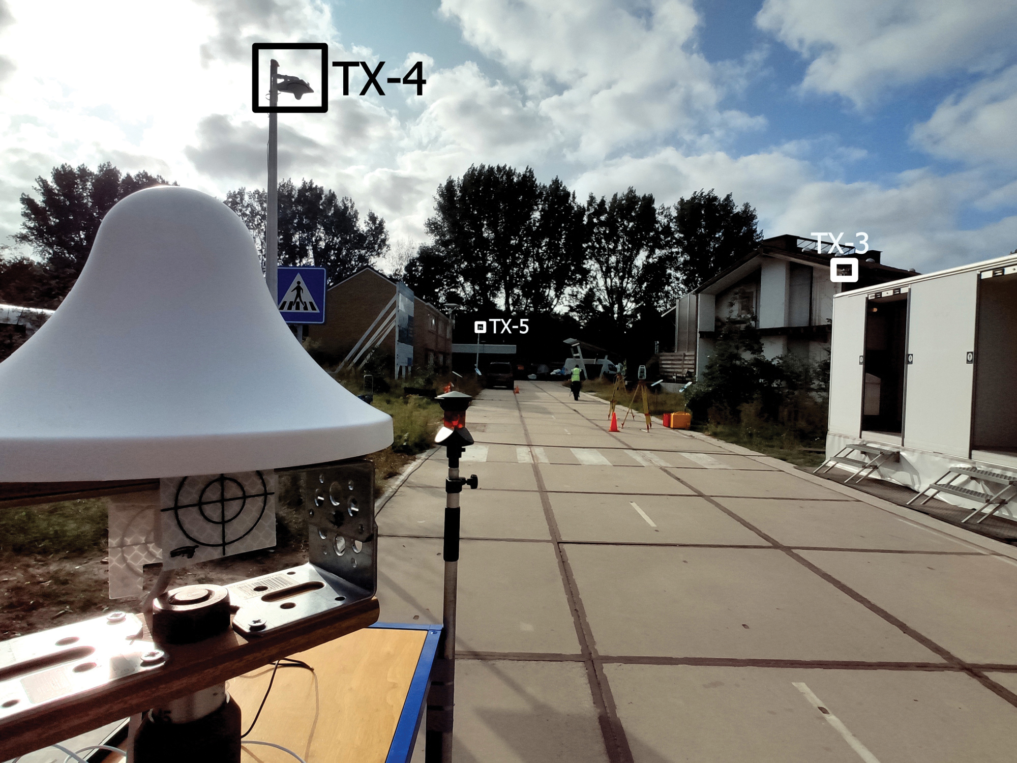
FIGURE 4. Test road at The Green Village, with three of the five roadside transmitting antennas (TX-3 to TX-5) as indicated. In the foreground, the receiver antenna is mounted on a trolley.
The road is bordered by built-up objects such as brick-wall houses, metal containers and large wooden advertising panels. These generate MPCs, which degrade the radio-positioning performance. The antennas TX-3, TX-4 and TX-5 can be seen mounted on lampposts. In Figure 4, the antennas TX-1 and TX-2 are on the right-hand sidewalk but not visible. The receiving antenna is in front to the left, mounted on a trolley. The RX antenna is identical to the ones used by the transmitters.
The receiver is used to perform a static survey at 50 locations on the road (staying at each point for around 1 minute). As shown in FIGURE 5, the receiver was also used for a kinematic experiment. The RX antenna is mounted on the roof of a car using a wooden beam. The RX antenna is linked via a 3-meter coaxial cable to the receiving SDR placed inside the car and connected to a host PC.
FIGURE 5. Receiver antenna mounted on the roof of a car. Two 360° prisms are used to determine the receiver ground-truth positions at the millimeter level, by means of land surveying total stations (placed on the yellow tripods in the distance).
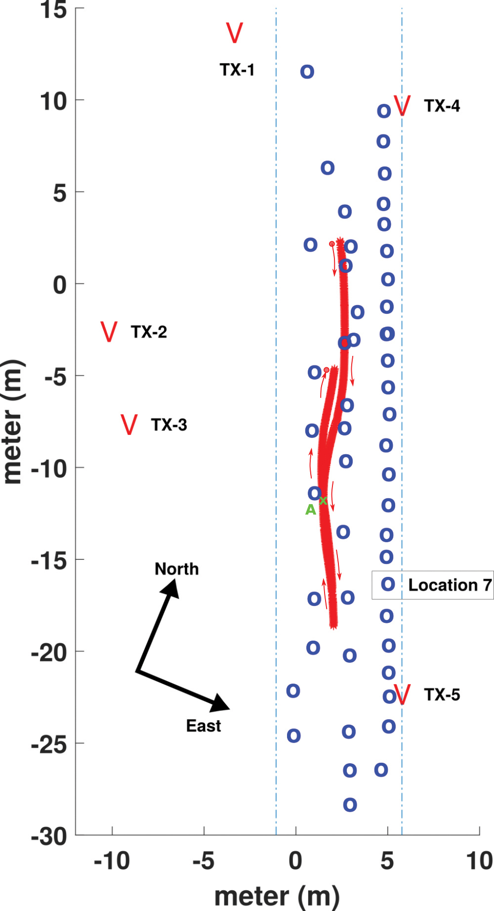
FIGURE 6 presents a map of the road with the static locations (in blue) and the forth-and-back kinematic track (in red). The transmitting antenna positions are indicated at both sides of the road.
FIGURE 6. Setup of the experiment on the local road at TGV. The locations of the transmit antennas, TX-1 to TX-5, are shown. Locations of static surveyed points are in blue, and the track of the kinematic experiment in red, with the RX antenna mounted on the roof of a car.
To establish a local coordinate system, the ground-truth positions of the RX antenna are determined using two land surveying total stations that rely on retro-reflective targets and 360° prisms to measure distances and angles. In Figure 4, a retro-reflective target, placed directly under the RX antenna, is visible, while the two total stations can be seen halfway down the road on the righthand side. In Figure 5, 360° prisms can be seen on both ends of the wooden beam on the roof of the car. The received signals are used to compute position solutions in post-processing, which are compared to the ground-truth values to assess the positioning accuracy. The accuracy of the ground-truth measurements is at the millimeter-level.
EXPERIMENTAL RESULTS
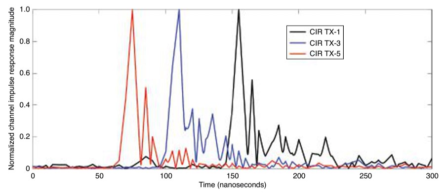
Achieving high positioning accuracy in a built-up area is difficult due to the presence of close-in MPCs, which arrive with very short time delays following the LOS component. FIGURE 7 shows the observed channel impulse responses (CIRs) between TX-1, TX-3, TX-5 and the receiver antenna RX placed at location 7 (see Figure 6). The LOS components can be easily detected as they correspond to the first and highest peak of each curve. However, we can also observe substantial close-in multipath components, which trail the main peaks. CIRs are obtained by division, in the frequency domain of the fast Fourier transform (FFT) of the received ranging sequences using the FFT of the known transmitted sequence. Oversampling by a factor of 100 is applied, as well as removing time delays of the TDM-scheme, such that the observed time delay difference directly represents the differences in ranges.
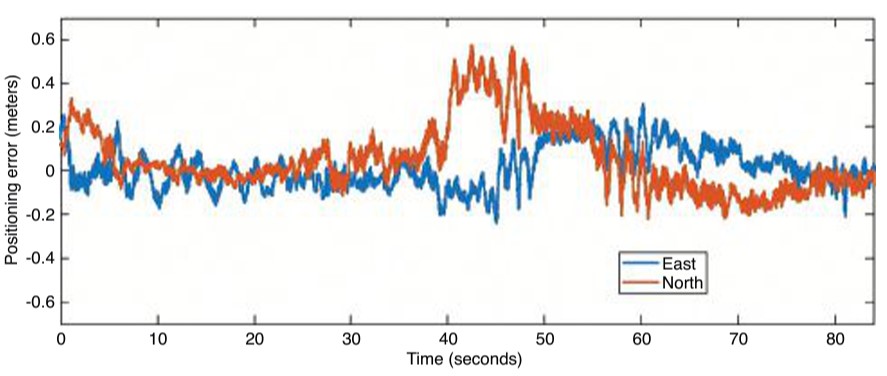
FIGURE 7. Normalized magnitude of the CIRs observed between the transmit antennas TX-1, TX-3 and TX-5 and the receiver antenna RX, positioned at reference point 7.FIGURE 8. Time series of the positioning error in the east and north directions during the kinematic experiment.
Since the TNPS signal bandwidth is 160 MHz, the time resolution is about 6.25 nanoseconds, which corresponds to about 1.9 meters of propagation distance. A multipath component, which arrives at the RX antenna with a lag larger than 6.25 nanoseconds with respect to the LOS component, is likely to be resolved and will not affect (bias) the ranging result. In this case, using time-of-flight techniques, ranges between TX and RX antennas can be determined, often at decimeter level, by extracting the time-of-arrival of the LOS components. Comparatively, if a 20 megasamples per second rate is used (corresponding to a 20 MHz bandwidth, commonly used in GNSS), the time resolution is 50 nanoseconds. An LOS component and a multipath component arriving at the RX antenna can likely be discriminated if the receiver and the reflector are separated by at least 15 meters. If the arrival time between the two components is less than 50 nanoseconds, then the MPC cannot be resolved and will cause a bias when determining the propagation distance between the TX and RX antenna.
The first and largest peak of each CIR seen in FIGURE 7 represents the LOS component. MPCs can be seen trailing the LOS, typically within the next 50 nanoseconds. The MPCs cause a bias in the estimated range when they cannot be resolved. Using wideband ranging signals allows for better time resolution, and better discrimination between the LOS component and the MPCs.
In the following, we assess the 2D positioning accuracy obtained using the demonstrator. 3D positioning is also possible with the demonstrator; however, since the TX antennas all are installed at similar heights and at a fairly low elevation compared to the RX antenna, we restrict our analysis to 2D positioning for the reason of having a poor geometry for determining the vertical position component. The 2D positioning model uses time difference of arrival (TDOA) pseudoranges allowing the cancellation of the asynchronous receiver clock offset. The frequency offset between the transmitters and the receiver has been estimated to be about 1 kHz, in asynchronous mode. After the TDOA ranges are computed from the experimental data, the 2D positioning problem is solved through Gauss-Newton iteration. Statistics of the static and kinematic 2D experiments are presented in TABLE 1.
TABLE 1. Static and kinematic positioning performance in terms of mean, standard deviation (std) and RMSE of position error, in east and north directions.
In the table, we present the mean position errors, standard deviations and root-mean-square errors (RMSEs) over the 50 surveyed points for the east and north directions. Mean errors of 6.4 and 4.3 centimeters are obtained for east and north directions, respectively. There is no significant bias in the system. In terms of RMSE, we can see that the positioning accuracy is just above 10 centimeters (11.6 and 15 centimeters respectively for the east and north directions). Overall, even with the presence of MPCs, and thanks to the synchronization accuracy and the wideband radio signals, a decimeter-level accuracy is achieved in static positioning.
The duration of the kinematic experiment was 84 seconds. Looking at the statistics of the kinematic experiment, the results for the east and north directions show a small bias and RMSE values of 9.2 and 16.4 centimeters respectively. The positioning performance in static and kinematic mode is close, both for the east and north components. In both cases, positioning performance is better in the east direction than in the north direction. This may be explained by better spatial diversity of the antennas towards the east direction. The time series of the position errors for the kinematic experiment is presented in FIGURE 8. Overall, the track error in the eastern direction is within ±2 decimeters (at a 95% confidence level). For the northern direction, a larger deviation is observed in the observation time span from 40 to 50 seconds (forward track), where the error in the north direction is close to 4 decimeters. Such a deviation is likely due to close-in MPCs resulting in a degradation of the accuracy for that part of the track. As a consequence, 82% of the position error in this track lies within ±2 decimeters. Outside this time span, the performance in east and north directions is similar.
CONCLUSIONS
This article presents the concept and results of a demonstration of a TNPS that uses WR to synchronize the transmissions of wideband radio ranging signals to achieve decimeter-level position accuracy in multipath environments, such as in built-up areas. A proof of concept of the TNPS was implemented at TU Delft. The developed prototype system demonstrates a decimeter-level 2D positioning accuracy in an urban road-like configuration bordered by built-up surroundings that cause substantial multipath.
ACKNOWLEDGMENTS
The research described in this article is supported by the Dutch Research Council, Nederlandse Organisatie voor Wetenschappelijk Onderzoek. We thank Lolke Boonstra and Terence Theijn from TU-Delft ICT-FM, as well as Rob Smets of SURF, the collaborative organization for ICT for Dutch education and research for their support and expertise on the optical infrastructure, and Loek Colussi and Frank van Osselen of Agentschap Telecom and René Tamboer and Tim Jonathan of The Green Village for their support in realizing the SuperGPS demonstrator. We also thank project partners Koninklijke PTT Nederland (KPN), Optical Positioning Navigation and Timing (OPNT) and Fugro.
MANUFACTURERS
The WR timing nodes V1.15 are by OPNT. The SDR systems for the transmitters and receiver are National Instruments (Ettus) X310 Universal Software Radio Peripherals. The 3-dBi wide-band antennas CM.02.03 are from Taoglas.
CHERIF DIOUF was a postdoctoral researcher in the Department of Geoscience and Remote Sensing at Delft University of Technology (TU Delft).
HAN DUN was a Ph.D. student in the Department of Geoscience and Remote Sensing at TU Delft.
GERARD JANSSEN is an associate professor in the Circuits and Systems Group of the Microelectronics Department at TU Delft.
ERIK DIERIKX is the principal scientist at Electricity & Time at the national metrology institute VSL in Delft.
JEROEN KOELEMEIJ is an assistant professor in the Department of Physics and Astronomy at the Vrije Universiteit Amsterdam.
CHRISTIAN TIBERIUS is an associate professor in the Department of Geoscience and Remote Sensing at TU Delft.
“Seen & Heard” is a monthly feature of GPS World magazine, traveling the world to capture interesting and unusual news stories involving the GNSS/PNT industry.
Image: Stadium, OnePlan/Paris 2024 Organizing Committee for the Olympic and Paralympic Games
PARIS OLYMPICS GET DIGITAL TWIN
In an Olympic first, the 2024 Olympics and Paralympics in Paris will receive a digital twin for planning and collaboration. OnePlan’s GIS Mapping and Venue Twin software will be used to create a 3D map of each sports venue and surrounding areas to help event planners, partners and suppliers collaborate in real time. They will be able to see spaces and capacities at any angle, in any light, in any weather condition at any time. Infrastructure such as barriers, fencing, vehicles, teams, volunteers and broadcast cameras can be positioned in the twin. Organizers can plan for any scenario, improving efficiency and safety, as well as take the needs of the disabled into account.
Photo: DeepRoute.ai
HOW WILL THEY SPEND THEIR TIPS?
A fleet of 30 “Robotaxis” – Level 4 autonomous cars – will hit the streets in Shenzhen, China, to showcase an autonomous solution by DeepRoute.ai. The Robotaxis – SAIC Motor SUVs outfitted with DeepRoute.ai’s Driver 2.0 – preview plans for mass production of autonomous vehicles in 2024, including for purchase by consumers. Autonomous cars are classified in five levels, with Level 5 the highest. A human driver can take over a Level 4 vehicle. Level 4 consumer vehicles on the road also gather data that is used to further improve Level 4 autonomous driving.
Switchblade 600. (Photo: AeroVironment)
GHOST DRONES TO HELP UKRAINE
The United States has committed more than $4 billion in security assistance to Ukraine, including on April 21 more than 121 Phoenix Ghost tactical unmanned aerial systems. The drones were rapidly developed by the Air Force specifically to meet Ukraine’s requirements. The Ghost drones are manufactured by Aevex Aerospace and have similar capabilities to the single-use “kamikaze” Switchblade UAS from AeroVironment, which also are being provided to Ukraine forces. The Switchblade 600 shown here is designed to destroy tanks and other armored vehicles. It weighs slightly more than 120 pounds and has a range of more than 40 miles.
Photo: NASA/JPL-Caltech/University of Arizona/USGS
OUR MARTIAN ADVENTURE
NASA’s Ingenuity UAV has now spent more than a year on the surface of Mars, with 21 flights under its belt. It is now scouting potential routes for its companion, the Perseverence rover. Most recently, Ingenuity traveled to the Séítah region to examine an extinct river delta, covering 1,150 feet and navigating around a large hill, to help determine the best route into the delta. The NASA team continues to gently push the drone’s capabilities to better understand improvements that can be applied to future Mars UAV designs.
Russian jets using GPS receivers, while ground vehicles use paper maps
GPS receivers have been found taped to the dashboards of Russian jets downed in Ukraine, according to a report from Express. The Express received the information from Ben Wallace, United Kingdom defense secretary, who mentioned it in a speech at the National Army Museum.
The GPS receivers were found taped to the dashboards of Russian SU-34s because of “the poor quality of their own systems,” he said. It is unclear whether he was referring to the Russian GLONASS satellite navigation system or the navigation systems aboard the SU-34 jets, but most likely the latter. Lack of maintenance and modernization of Russian military equipment has been obvious since the beginning of Russia’s invasion of Ukraine.
As for navigation on the ground, many vehicles were found with paper maps from the 1980s, Wallace said.
Russian ground vehicles also lack situational awareness and digital battle management, he said, while the large amount of footage from Ukrainian drones points to a lack of wider air defense, including counter-UAV systems.
In a different news story from the war, Ukraine may be receiving Raytheon-built GPS-guided artillery rounds.
As PNT becomes critical to more economic activities, any disruption in availability, reliability, resilience and integrity would weaken the critical infrastructure that sustains national security, business operations and public safety, according to experts speaking at the Geospatial World Forum.
This growing dependency on PNT services — and the potentially high economic cost of vulnerabilities — underscores how vital GPS and GNSS systems are to the global economy and national security of countries worldwide, the experts said. Resilient PNT systems are necessary to combat GPS/GNSS outages.
Robert Cardillo (Photo: GWF)
Building resilience into these systems will require multiple technologies ranging from network time-transfer services to terrestrial wireless infrastructure and low-Earth-orbit (LEO) satellites.
The Geospatial World Forum opened in Amsterdam on May 10. The second plenary of the day focused on the value of PNT in the global economy. Geospatial World is a global think tank working towards raising awareness around the use of geospatial data and technologies among governments and policymakers, businesses, and the public at large.
Robert Cardillo, president of The Cardillo Group and former director of the U.S. National Geospatial Intelligence Agency (NGA), headed the panel of experts.
“Our existence on this planet has been shaped by our individual and collective awareness of place and our confidence to be able to move securely and efficiently from one place to another, all within that common framework of position, navigation and timing, or PNT,” he said.
“The smartphone is a wonderful example of how far PNT has been integrated into our lives,” said Trimble founder Charlie Trimble. He laid down three basic phases involved in leading PNT to its place in the world economy.
“The path from the dawn of space age to the smartphone was anything but obvious or straightforward,” Trimble said. “First, Sputnik led to the global navigation systems. Second, the Shuttle disaster led us to the realization that the satellite system was an information utility. And now, the integration of PNT into the mobile and immobile internet is changing our world.”
From left: Charlie Trimble, Martin Sweeting, Rodrigo da Costa and Gillian Smith. (Photo: GWF)
“Our first contract was with ESA (European Space Agency) to look at the feasibility of using a navigation and timing satellite using small-satellite techniques, which in 1985 was considered a wacky idea,” recounted Martin Sweeting, executive chairman of Surrey Satellite Technology Ltd. “At ESA, we have embarked on a project called Hydro GNSS, which uses Surrey’s GNSS reflectometry to address several climate related issues, be it water detection or biomass, etc. This doesn’t stop here; we are looking at the lunar economy. PNT has indeed a very bright future, not just on Earth but also looking through this decade into the use of PNT on the lunar surface.”
Rodrigo da Costa
“New things are happening, particularly in the area of governmental satellite communications, space situational awareness and others, which are benefitting citizens every day,” said Rodrigo da Costa, executive director, EU Agency for the Space Programme (EUSPA). “Galileo, EGNOS (European Geostationary Navigation Overlay Service), Copernicus and GOVSATCOM programs are key areas of EU space activities. All these programs are massive investments and in the end, the result comes from their utilization in the different areas of our economy and daily life.”
“Just in the United States alone, GPS is approaching USD 1 trillion in terms of economic impact and is doubling every 2-3 years. But it is a single point of failure. This highlights the need for resilient PNT,” said Gillian Smith, vice president of marketing, NextNav. “We believe that our needs have evolved beyond technology that was really created in the ’60s. We need increased accuracy and availability in the urban environments in particular.
“I think many of you have experienced it if you’ve tried to use it in any major city,” Smith said. “That blue dot is going to bounce off of buildings and not be very accurate. We need indoor tracking and mapping. We need altitude data so that you know what floor you’re on when you’re thinking about accurate location. We also need to increase resilience and redundancy. That’s going to give us all increased security as well.”
The Value of GPS
GPS jamming and interference is a grave issue that has come under the spotlight particularly since the Russian invasion of Ukraine, according to Geospatial World.
In 2019, a Washington, D.C., think tank documented more than 10,000 cases of GPS interference (jamming and spoofing) in the previous five years from Russia. By 2021, these had become increasingly sophisticated. In a peculiar case, the crew onboard NATO ships in Odessa saw their position being given as Crimea.
In the past six months, even before the war on Ukraine began, there were reports of GPS jamming in and around that region. In March, the EU Aviation Safety Agency had issued warnings of GNSS spoofing and jamming for flights over Europe, in particular around countries neighboring Ukraine and Russia.
Globally, the economic impact of GPS/GNSS disruption is difficult to state. The potential economic consequences of failing to sufficiently protect sources of PNT are enormous, with estimates ranging from millions to billions of dollars depending on the type, length, severity and geographic scope of the disruption.
Furthermore, the impact of a GPS/GNSS outage extends beyond basic economics and could result in risk to life. Emergency services, distress beacons and telecommunications networks all rely on PNT services — any disruption could cause serious consequences.
A 2019 report sponsored by the National Institute of Standards and Technology estimated that the loss of GPS would cost the U.S. economy USD 1 billion a day.
A 2017 study in the United Kingdom estimated a five-day GNSS disruption would lead to an economic impact of GBP 5.2 billion (USD 7.2 billion), with road, maritime and emergency service impacts accounting for 88 percent of the cost.
Image: GPS World; outdoor, Andriy Solovyov/Shutterstock.com; indoor, Rade Kovac/Shutterstock.com
\Registration is now open for the fifth GNSS Raw Measurements Task Force meeting, which will take place on May 17. Participation is online, where participants will gain access to Task Force members’ experience and learn about progress on using raw measurements in Android devices.
The aim of the EUSPA’s Raw Measurements Task Force is to bridge the knowledge gap between raw measurement users. The meetings of the task force are a key element in this effort, providing a forum for stakeholders to share experience and knowledge around raw measurements use.
Following a welcome address from Fiammetta Dianithe, EUSPA’s head of Market, Downstream and Innovation (MADI) Department, the opening session will include a keynote presentation from Google`s Frank Van Diggelen and Mohammed Khider. Updates on EGNSS opportunities from the Galileo programme will be provided by members of the MADI team.
After the break, the agenda will be dedicated to presentations from Task Force members, targeting their innovative work using raw measurements. The last session focuses on testing results and implementation of EGNSS differentiators. For the full draft agenda, click here.
Since its launch in 2017, the task force has expanded from a handful of experts to a community of more than 100 agencies, universities, research institutes and companies. Membership is open to anybody interested in GNSS raw measurements. To join the task force, contact [email protected].