Blog

  • Meeting the autonomy promise: Advanced navigation for sea, land and air

    Meeting the autonomy promise: Advanced navigation for sea, land and air

    A 2019 RAND report for the U.S. Navy concluded that autonomy could still be in the distant future. The Navy should take care that a number of claimed autonomy applications could be more aspirational than practical, the report stated, with the applications nowhere near to operational capability. The authors wrote that huge investments may be required to achieve autonomous naval weapon systems, not only in autonomy.

    Around the world in recent years, most armed forces and many advanced technology companies, along with government agencies, have been investing in AI and automation. Perhaps now, just six years later in 2025, we already are looking foward to unmanned vehicles that display not just fundamental autonomy, but also quite advanced “auto-capability.”

    In the world’s water

    The U.S. Navy (USN) has been operating a number of unmanned surface vessels (USV) over the past several years. In a 2023/2024 Pacific Fleet exercise, four USV models (Sea Hunter, Sea Hawk, Mariner and Ranger) were mostly operated autonomously. Ranger has a small bridge manned only for harbor maneuvers.

    An Orca extra large UUV (XLUUV) is tested in a tank. With a range of 6,500 nautical miles, the submarine can perform long missions. Its navigation system features a Kalman-filtered inertial unit supported by Doppler velocity logs and depth sensors. Photo: Boeing
    An Orca extra large UUV (XLUUV) is tested in a tank. With a range of 6,500 nautical miles, the submarine can perform long missions. Its navigation system features a Kalman-filtered inertial unit supported by Doppler velocity logs and depth sensors. Photo: Boeing

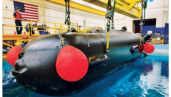
    The USN has unmanned autonomy programs for large, small and underwater vehicles. The Orca submarine program is slated to consist of five 51-foot-long vehicles, and includes variants fitted with an added 30-foot payload section. To operate for several months underwater, it is likely that a similar degree of autonomy has been incorporated. ORCA surfaces regularly and can be given new routing if required.

    Saildrone's autonomous research vessel (Photo: Saildrone)
    Saildrone’s autonomous research vessel (Photo: Saildrone)

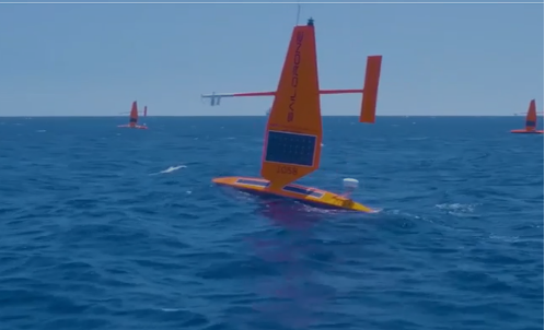
    Other types of vessels collect ocean and seafloor data. The environmentally friendly Saildrone can operate independently — we could say autonomously — for more than a year. The Saildrone company, based in Alameda, California, contracts out its USVs, providing its technology to agencies and governments and taking on the risks of ocean surveying to acquire valuable data. Saidrones are equipped with satellite communications, GNSS navigation, weather sensors and sub-surface sensors.

    Wheels on the road

    Autonomy applications on land are dominated by commercial self-driving cars, Tesla being the leading manufacturer in the U.S. However, full autonomy is still a considerable way from being ready. At the full-autonomy level, known as Level 6 in the auto industry, the vehicle does all the driving, including obstacle avoidance, under all conditions, without any geographic limitation. Nevertheless, we appear to have progressed from basic manual control (Level 0) to somewhere around Level 3, where the vehicle is largely aware of its environment, and does most of the driving. Even so, human monitoring and control are still required.

    Tesla’s autopilot technology in its Model S and Model X electric vehicles could be referred to as an advanced driver assistance system — or as Tesla calls it, “Full Self-Driving (Supervised)” — and is reported to handle emergency steering and braking, autonomous steering, lane changing, vehicle following, curve negotiation, and automatic parking. Autopilot sensor inputs are provided by 12 ultrasonic sensors and eight cameras providing a 360° field of view.

    Tesla Autopilot intelligence can identify more than 250 traffic signs 50 countries, including turn signs and speed limits. It can identify and interpret traffic lights and road markings, and decide what to do when coming across things such as traffic cones and pedestrians.

    Nevertheless, Tesla’s have been involved in quite a few accidents, the cause of which has been analyzed to be mostly a lack of driver attention (supervision), and in a number of cases, a failure of the autonomous system to recognize unusual road conditions.

    Another company, Leo Drive, specializes in providing scalable software and hardware solutions, offering an end-to-end, one-stop service for integration of autonomous systems. Its mission is to make autonomous technology more accessible and widely adopted across various industries.

    For its autonomous test vehicle, Leo Drive is using the Ellipse-D, a dual-antenna RTK inertial navigation system (INS) from SBG Systems. The company chose the Ellipse-D for its accuracy, reliability, and advanced features — all essential for autonomous vehicle development and testing. The Ellipse-D INS was integrated into Leo Drive’s, a passenger car converted for autonomous operations.

    Oshkosh Defense integrated autonomous technology onto Palletized Load System vehicles as part of the Expedient Leader Follower program. Photo: Oshkosh Defense
    Oshkosh Defense integrated autonomous technology onto Palletized Load System vehicles as part of the Expedient Leader Follower program. Photo: Oshkosh Defense

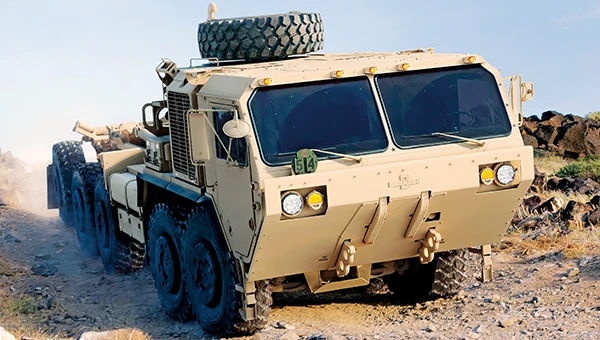
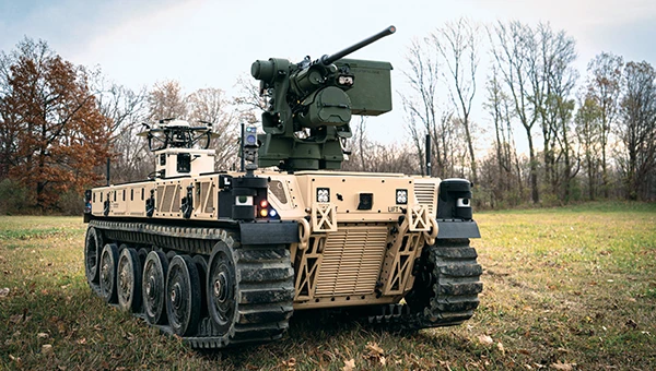
    The U.S. Army has been using automation in its weapon systems for some time. How much autonomous behavior, of which these systems are truly capable, may be difficult to determine. The General Atomics Reaper unmanned aerial vehicle (UAV) is largely controlled over long-distance satellite links by operators in control stations. It’s possible that the same set up is true of most of the Army’s automated weapons — probably motivated by the need to avoid systems independently determining their own targets and firing without human confirmation.

    It’s difficult to determine just what army programs are underway, other than to acknowledge that programs have been launched in the past. There doesn’t appear to be any open, clear indication of the degree of autonomy to be included. A couple of programs have produced at least visible hardware, but how much or little human control is involved is unclear.

    Taking flight

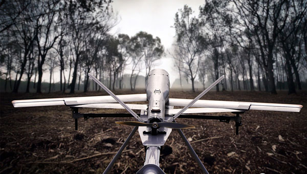
    Up in the air, new autonomy contender Mayman Aerospace is offering the Razor, a jet-powered vertical take-off and landing (VTOL) UAV. Development of Razor is funded by private investment and U.S. Department of Defense contracts.

    The RAZOR VTOL with gimbled jet pods passed tests at a military base in California in September 2024. Photo: Mayman Aerospace
    The RAZOR VTOL with gimbled jet pods passed tests at a military base in California in September 2024. Photo: Mayman Aerospace

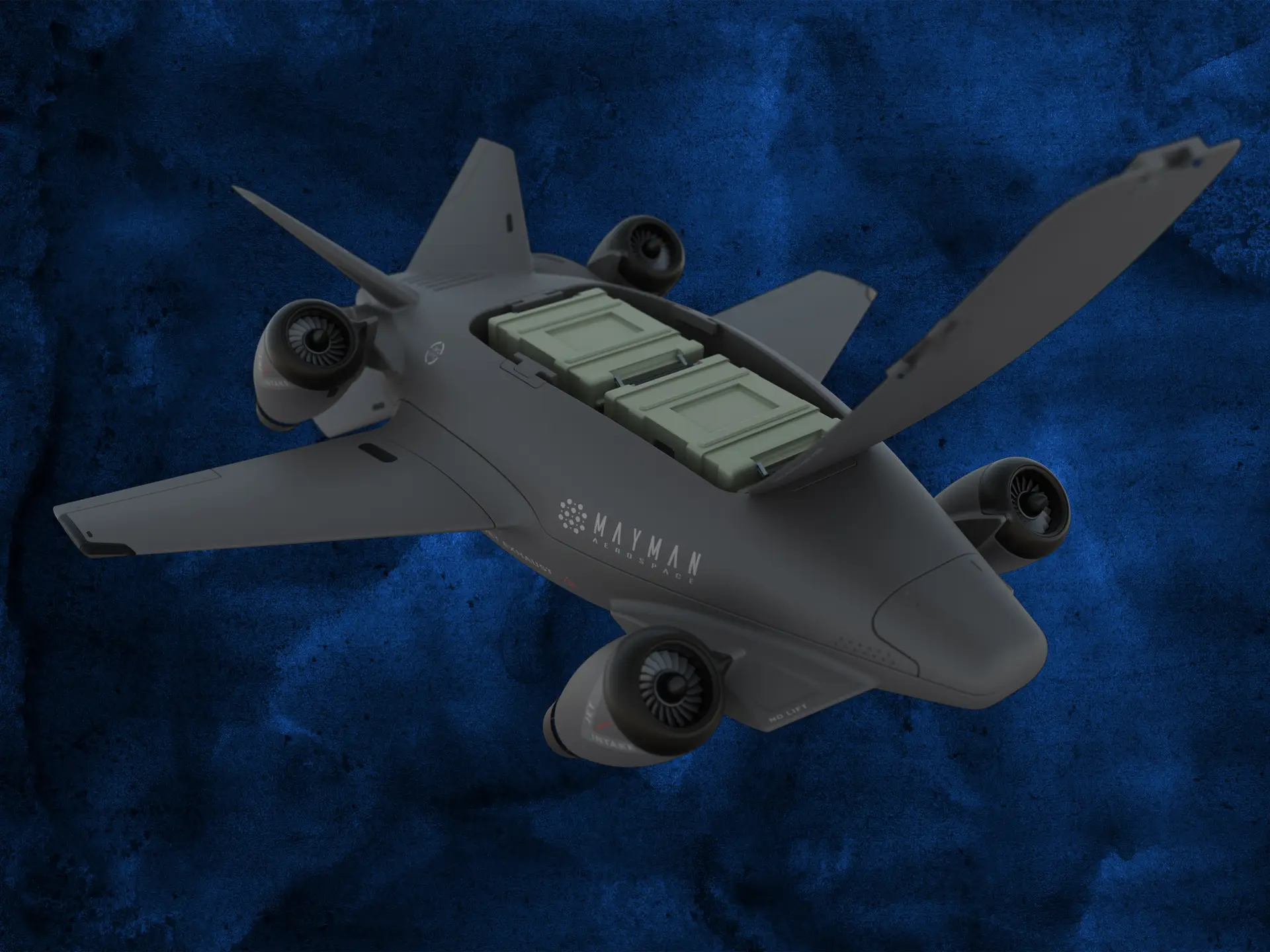
    Razor is imbued with a degree of AI that enables autonomous decision-making, as well as navigation. Its autonomous AI brain — the SkyField flight-control system — navigates independently in a GPS-denied environment, possibly involving ground beacons and eventually integrating with battlefield management systems. With a 5- to 6-foot-long airframe and sculpted shape, the aircraft presents a low radar cross section and has a degree of stealth to assist in the penetration of enemy defenses. Its top speed of 500 mph provides new options for both military and commercial applications, according to Mayman.

    Razor also can aid disaster recovery, rescue operations, and the delivery of urgently needed life-saving cargo.

    Many VTOL unmanned aircraft have struggled with the transition from vertical to horizontal flight. On its first vertical lift-off and climb-out on four jet engines, Razor paused briefly at altitude. Then its jet pods tilted slightly toward horizontal before the aircraft went directly into horizontal flight. An earlier flying testbed may have assisted the development of transition software, perhaps with a boost from machine learning.

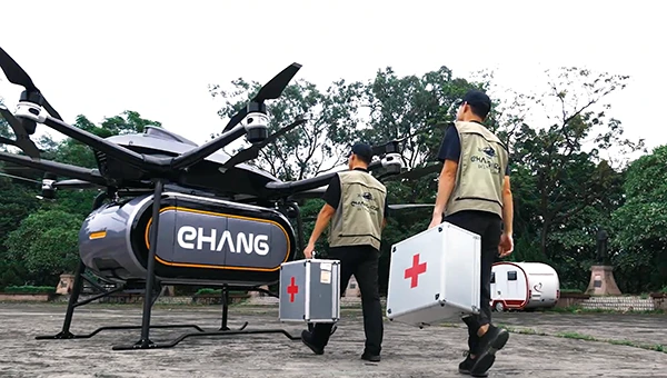
    Designed for deliveries, the EHang 216 heavy cargo, 16-rotor unmanned aircraft can carry a payload of 551 pounds over almost 22 miles with a top speed of 80 mph, according to the EHang company. The UAV is fully autonomously operated while being monitored over a 4G/5G data link at a manned control center. The system has an automatic fail-safe mode in which the UAV will return to base if the communications link goes down or if battery power drops too low.

    EHang also uses a redundant design, with two GPS receivers and double rotors, ensuring a low likelihood of failure during a delivery run.

    More In development

    So while land vehicle autonomy is moving forward — with Tesla cars and Army vehicles that apparently can take control with close human monitoring — we still have some distance to go to achieve fully independent autonomous behavior on the road.

    The Ehang 216 heavy-cargo UAV EHang 216L is designed for deliveries, including life-saving ones. Photo: Ehang video screenshot
    The Ehang 216 heavy-cargo UAV EHang 216L is designed for deliveries, including life-saving ones. Photo: Ehang video screenshot

    Autonomous applications on the sea are more common, with U.S. Navy applications showing substantial progress. Still, precise navigation in crowded harbors remains under human control. Humans are still watching and monitoring, ready to intervene should military or commercial UAV applications make untoward execution errors.

    We will continue to follow developments of significant autonomy programs such as the U.S. Air Force Collaborative Combat Aircraft (CCA), a new type of uncrewed weapon system. The CCA and other programs are maintaining high investment levels, so it’s possible that we may see full autonomy fielded quite soon. Perhaps then our belief in its capability will become fully justified.

  • Sierra Space demonstrates resilient GPS technology for US Space Force

    Sierra Space demonstrates resilient GPS technology for US Space Force

    Sierra Space, a commercial space and defense technology company, has successfully completed another demonstration of its resilient GPS (R-GPS) technology for the U.S. Space Force. This achievement marks the third major milestone for the program, which is designed to enhance the resilience of GPS infrastructure against threats such as jamming and spoofing. The recent demonstration included early integration of R-GPS satellite technology using FlatSat flight software and hardware subsystem testing, as well as successful communication with ground software systems.

    The R-GPS effort is part of a broader initiative by the U.S. Space Force’s Space Systems Command to develop smaller, more cost-effective GPS satellites. Sierra Space was awarded a Quick Start contract in September 2024 to produce design concepts for these satellites, aiming to rapidly bring advanced technology to the national security space sector. The company’s progress comes just six months after the program’s inception, highlighting its ability to accelerate technology development in response to evolving defense needs.

    GPS technology is integral to both civilian life and military operations, supporting applications that range from smartphone navigation to critical defense activities. As adversarial threats become more sophisticated, the need for resilient GPS systems has grown. The R-GPS program addresses this by planning to augment the existing GPS architecture with a network of smaller satellites, which would provide additional layers of security and rapid deployment capabilities.

    The latest testing milestone demonstrated the flow of commands and telemetry between Sierra Space’s ground software and a ground stations service provider, establishing that the technology can operate effectively between orbit and ground-based facilities. The FlatSat testing format, where satellite components are evaluated while laid out flat, allowed for early integration of flight software and hardware subsystems.

  • LabSat launches scalable solutions for GNSS signal testing

    LabSat launches scalable solutions for GNSS signal testing

    LabSat has expanded its GNSS signal record, replay and simulation portfolio with the introduction of three new LabSat 4 variants: LabSat 4, LabSat 4 Core and LabSat 4 Lite. LabSat seeks to provide engineers and developers with scalable solutions tailored to a wide range of testing requirements and budgets.

    LabSat 4 delivers advanced capabilities, including up to 12-bit I&Q quantization and support for recording and replaying external data such as CAN-FD, RS232, and digital inputs. This model is designed for demanding GNSS signal testing, offering high precision and extensive customization to address complex modern testing scenarios.

    LabSat 4 Core offers the same features as the original LabSat 4, except it is limited to a maximum of 4-bit I&Q quantization. This makes it a cost-effective choice for applications where the highest signal capture resolution is not necessary, while still providing a comprehensive feature set.

    LabSat 4 Lite is optimized for affordability, featuring streamlined 2-bit I&Q quantization and omitting external data recording and replay. It is well-suited for production line testing and other scenarios where quantization depth is not a critical factor.

    All LabSat 4 variants include three RF channels with selectable bandwidths up to 60 MHz, adjustable quantization options depending on the model, manual gain control, multi-unit synchronization, and full backward compatibility with LabSat 3 Wideband file formats. The series is compact, portable, and designed for efficient use in both field and laboratory environments.

    A key benefit of the LabSat 4 range is the ability to upgrade between models via a license file, allowing users to start with LabSat 4 Lite and move to Core or the full LabSat 4 as their testing needs evolve, without replacing hardware. Customers can also select between Replay-Only and Record-and-Replay configurations across all variants.

  • NVS-02: Navigation signals from transfer orbit

    NVS-02: Navigation signals from transfer orbit

    NVS-02 is a second-generation navigation satellite of the Indian regional navigation satellite system NavIC. It was launched on Jan. 28, 2025, but could not reach its designated orbit due to a malfunction of a valve of the thrusters. Thus, the satellite is still in its transfer orbit. As of April 2025, the NVS-02 perigee is about 190 km, whereas the apogee is 37,400 km above the Earth’s surface. The inclination is about 21° and the eccentricity is 0.74. The groundtrack of NVS-02 is illustrated in Figure 1 and currently has a repeat cycle of about six days.

    As of today, starting on Feb. 19, 2025, a decent number of receivers of the International GNSS Service are tracking the L5 signal of NVS-02 with the pseudo-random noise number I11. The L5 tracking of dedicated stations on individual days is indicated by different colors in Figure 1. Although the groundtrack has global coverage, no stations in Northern and Southern America have tracked I11 so far. The tracking is limited to periods when the satellite is near the apogee with altitudes between 23,000 km and 37,400 km and visible from the Indian Ocean region. During these periods, indicated in pink in Figure 1, the transmitter is active and the antenna is roughly pointing toward Earth.

    Figure 2 shows the carrier-to-noise density ratio (C/N0) of the NVS-02 L5 signal tracked by a Septentrio PolaRx5 receiver at the German Space Operations Center (GSOC) of the German Aerospace Center (DLR) in Oberpfaffenhofen, Germany. Sudden drops in the C/N0 occur at about 8°, 28°, 46° and 52°. Here, the line of sight to the satellite is at the edge of the transmit antenna main lobe with a significantly lower gain, introducing the drop in signal power and, finally, the loss of lock.

    Figure 2: Elevation-dependence of the carrier-to-noise density ratio of the NVS-02 L5 signal at Oberpfaffenhofen, Germany. (All figures provided by the authors)
    Figure 2: Elevation-dependence of the carrier-to-noise density ratio of the NVS-02 L5 signal at Oberpfaffenhofen, Germany. (All figures provided by the authors)

    The spectral flux density of NVS-02 in the L5, L1 and S band is shown in Figure 3. The L-band spectra have been measured with GSOC’s 30 m high-gain antenna in Weilheim, Germany. As the feed of this antenna is limited to the L band, the S band spectrum has been recorded with a 5 m dish antenna of DLR’s Institute of Communication and Navigation.

    Figure 3: Spectral flux density of NVS-02 in the L5 (top), L1 (middle) and S-band (bottom). (All figures provided by the authors)
    Figure 3: Spectral flux density of NVS-02 in the L5 (top), L1 (middle) and S band (bottom). (All figures provided by the authors)

    The peak in the L5 spectrum at the center frequency of 1176.45 MHz is related to the civil Standard Positioning Service and introduced by a Binary Phase Shift Keying (BPSK) modulation with 1 MHz bandwidth. The two broader peaks with an offset of 5 MHz from the center frequency are caused by a Binary Offset Carrier (BOC) signal of the Restricted Service with a bandwidth of 2 MHz. Sidelobes of that signal are visible at the center frequency ±15 MHz and ±25 MHz.

    For the L1 band, a Synthesized Binary Offset Carrier (SBOC) is used. It consists of two BOC signals with 1 MHz bandwidth and offsets of 1 MHz and 6 MHz, respectively. The two mainlobes of the BOC (1,1) component are visible at 1575.42±1 MHz, and the mainlobes of the BOC (6,1) component at 1569 MHz and 1581 MHz. The same type of signals, as in L5, are transmitted on the S band carrier with a center frequency of 2492.028 MHz. Due to its different location in a less remote area, compared to the 30 m antenna in Weilheim, the 5 m antenna in Oberpfaffenhofen suffers from pronounced interference with other signals in the S band; the most prominent peak can be seen at 2480 MHz, several smaller and sharper peaks over the whole frequency range shown in the lower plot of Figure 3. Possible causes of these interferences are WiFi and civilian and military radiocommunication services.

    Although NVS-02’s mean orbit height is steadily decreasing due to the atmospheric drag around the perigee, the satellite will stay in orbit for at least a decade. However, navigation signal transmission might stop at any time due to operational constraints or unfavorable conditions in the non-nominal orbit.

  • SiTime unveils mobile clock generator with embedded MEMS

    SiTime unveils mobile clock generator with embedded MEMS

    SiTime Corporation has introduced Symphonic, its first mobile clock generator featuring its integrated MEMS resonator, the SiT30100. The device is designed to deliver precise and resilient clock signals for 5G and GNSS chipsets, supporting efficient power consumption in mobile and IoT devices, including smartphones, tablets, laptops and asset trackers. According to SiTime, the Symphonic clock generator combines the functions of up to four separate timing devices, which helps simplify system design and reduces circuit board space requirements.

    The integrated temperature sensor in the SiT30100 provides accurate data to compensation algorithms, enabling improved frequency stability. This results in improved GPS accuracy and faster lock times, which are critical for maintaining stable performance in challenging environmental conditions. The device operates within a temperature range of -30°C to 90°C and is engineered for dynamic stability and power optimization, helping to mitigate electromagnetic interference.

    Symphonic offers four clock outputs, each capable of delivering 76.8 MHz, 38.4 MHz or 19.2 MHz, suitable for baseband, radio frequency and GNSS applications. The integrated MEMS resonator eliminates the need for an external resonator, resulting in a compact, single-chip solution with an area of 2.22 mm². The device also features a high-precision temperature-to-digital converter with a single-wire UART interface, supporting frequency stability as low as plus or minus 0.5 parts per million.

  • First all-Canadian Antarctic expedition creates underwater maps using GNSS technology

    First all-Canadian Antarctic expedition creates underwater maps using GNSS technology

    Canadian scientists recently led their first Antarctic research expedition, using Montreal-made Arrow Gold+ GNSS technology for precise location data in remote and challenging conditions. The mission, which departed in early March 2025 aboard HMCS Margaret Brooke, included experts from multiple Canadian universities and government agencies. Researchers conducted water, sediment, air, and sea-ice sampling to study climate change, glacial retreat and pollution such as mercury and microplastics.

    The month-long journey around the South Shetland Islands and the northern Antarctic Peninsula yielded surveys of coastal and oceanic sites. The crew relied on a small, unmanned surface vessel (USV) carrying various equipment for bathymetric surveys including an onboard computer, IMU and multibeam sonar.

    In order to find the USV’s precise position in an environment with no land-based RTK infrastructure, the team relied on the Arrow Gold+ GNSS receiver, designed and manufactured by Canadian-based Eos Positioning Systems. The Arrow Gold+ utilized Galileo High Accuracy Service (GalHAS), a free satellite-based PPP correction available worldwide from the European Union’s Galileo Programme.

    “There aren’t any RTK networks in Antarctica,” said Kevin Wilcox, Ocean Mapping Group research scientist, who piloted the USV. “That sent us looking for the Arrow Gold+ and GalHAS corrections. When we found these, we realized we had a possible solution.”

    While using GalHAS corrections, the Arrow Gold+ provided estimated accuracies of about 10 cm horizontal and 15 vertical to 20 vertical.

    “The vertical accuracy was especially important for our bathymetric work,” Wilcox said. “Any vertical error would directly add error to our depth.”

    Sites surveyed include Admiralty Bay, Livingston Island and Deception Island, which includes an active, flooded volcano caldera. The resulting, high-accuracy maps will support further scientific and oceanographic research, environmental monitoring, and improvements to marine charts.

    By adding high-accuracy locations with an average accuracy of 10 cm to 20 cm horizontal and vertical, the team was able to accurately georeference and further refine the detail of the bathymetry for their map inside the underwater Deception Island caldera. (Photo: Eos Positioning Systems)
    By adding high-accuracy locations with an average accuracy of 10 cm to 20 cm horizontal and vertical, the team was able to accurately georeference and further refine the detail of the bathymetry for their map inside the underwater Deception Island caldera. (Photo: Eos Positioning Systems)
  • AAGS launches geodetic surveying certificate: Key updates from joint NGS/NSPS/AAGS meeting

    AAGS launches geodetic surveying certificate: Key updates from joint NGS/NSPS/AAGS meeting

    As president-elect of the American Association for Geodetic Surveying (AAGS), I participated in a joint quarterly meeting with the National Geodetic Survey (NGS), the National Society of Professional Surveyors (NSPS) and AAGS on April 25.

    I invite you to visit the AAGS website and consider joining our monthly board meetings, which are held on the second Tuesday of each month. All are welcome to attend. If you are interested, email me at [email protected] to be added to the attendee list.

    Now, for some updates from the joint quarterly meeting.

    During the meeting, I provided an update on the Certificate for Geodetic Surveying program, which has been under development by AAGS and is expected to be available by the end of the year. The program is designed to meet the needs of surveyors and others that perform spatial analyses and computations using geodetic methods.

    Tim Burch, executive director of the National Society of NSPS, wrote the following in an April 23, 2025, xyHt article:

    “To the average professional surveyor, the term “geodesy” does not exist in their everyday conversations about the business. While the use of state plane coordinates has expanded greatly with the development of GPS/GNSS receivers and RTK/RTN connectivity, the mathematics and “black magic” of geodesy remains an enigma to most of the profession.

    However, the ongoing progression of technology within surveying instruments has expanded the need for understanding how geodesy works. Our practitioners are faced with expanding their knowledge and expertise of geodesy and thus have put a new challenge on them to find teachers and/or mentors to provide training on the datums and techniques.”

    This is exactly what AAGS is attempting to do with the Certificate for Geodetic Surveying program. The information below includes the program description and content. AAGS has developed a set of questions that will determine if an individual has demonstrated a minimum competence in understanding and applying geodetic surveying concepts. AAGS is working with NSPS, who will be administrating the program for AAGS. The status and updates of this program are provided at the AAGS Monthly Board meetings. Come join us to hear more about the program and other AAGS activities.


    Certification for Geodetic Surveying

    Program description and content. Certification for Geodetic Surveying is official recognition that a person has demonstrated to the satisfaction of the Certification for Geodetic Surveying Board that he or she is minimally competent to perform spatial analyses and computations using geodetic methods.  It is not intended to certify scientists performing research in geodesy.  Rather, it is for individuals who use geodetic concepts and techniques to solve practical problems as a part of performing their work.  Typical practitioners include geodetic surveyors, geodetic/geomatics engineers, geospatial software developers, geographic information systems (GIS) professionals, and geospatial data managers.  The focus is more on the use of applied geodetic methods than with a particular field.  A person who has obtained the Certification for Geodetic Surveying is one who has demonstrated minimum competence.  In this context, “minimum competence” is a combination of working knowledge and familiarity with geodetic concepts that shows the ability to understand and solve applied practical geodetic problems as normally encountered in modern geospatial practice.  Importantly, this includes an understanding of one’s limitations in solving such problems. 

    The Certification for Geodetic Surveying Board will identify the depth of knowledge required to achieve minimum competence for Geodetic Certification in the following areas:

    • Geometric geodesy
      •  Reference frames, reference systems, geometric datums, and realization strategies
      • Characteristics of modern reference systems, including NAD 83, WGS 84, ITRF, and IGS
      • Transformations between datums, both modern and historic
      • Geodetic, projected, and local geodetic horizon coordinate systems
        • Direct and inverse problems for geodesics and map projections
        • Reference ellipsoids, radii of curvature, and types of geodetic and projected distances
        • Reductions, conversions, and relationships between coordinate systems
        • Transformations used to create “localization/calibration” coordinate systems
    • Physical geodesy
      • Gravity, “the” geoid, gravimetric and “hybrid” geoid models, physical height systems, deflection of the vertical
      • Vertical geodetic datum definitions and transformations
      • Types of heights and their relationships; conversions between the various types
      • Terrestrial methods for vertical, horizontal, and 3-D positioning
        • Geodetic leveling and height determination; leveling instrumentation and corrections
        • Modern 3-D terrestrial methods and instruments, including total stations and scanners
        • Familiarity with historical methods such as triangulation, trilateration, and geodetic astronomy
    • Accuracy and error
      • Positional error estimation and uncertainty propagation; statistics and probability theory
      • Characterization using network and local accuracies, error ellipses, and confidence levels
    • Temporal aspects
      • Plate tectonics (both steady-state and episodic); plate-fixed versus no-net rotation reference systems; subsidence; isostatic adjustment; tidal deformation
      • Time-dependent transformations between reference systems
    • Global Navigation Satellite Systems (GNSS)
      • Instrumentation; system architecture; signal structure; error budget
      • Methods for position determination, including by pseudorange, differential correction, carrier-phase differencing, and precise point positioning
    • Geodetic survey networks
      • Design, adjustment, and analysis of GNSS and terrestrial geodetic survey networks
      • Formulation and solution of least-squares network adjustments
    • Standards and guidelines
      • Official standards, specifications, and guidelines for geodetic control, positioning, and accuracy
      • The US National Spatial Reference System and similar systems elsewhere

    Many of you are probably aware of the actions taken by the current administration to reduce the size of the U.S. federal workforce, these actions may affect all users of U.S. geospatial products and services.  NGS is not exempt from these actions; recently, they have lost many employees either though leaving service voluntarily, retiring earlier than planned, or having been terminated because they were still in the probation period of their employment. NGS leadership did not provide any details on changes in personnel; only time will tell what the loss of personnel will have with the agency in the future. That said, NGS’s plans still include transitioning the modernized NSRS Alpha Site to a Beta Site this year. The current alpha site has four products — State Plane Coordinate System. SPCS2022, NGS Coordinate Conversion and Transformation Tool (NCAT), Euler Pole Parameters (EPPs) and The North American-Pacific Geopotential Datum of 2022. My understanding is that all four of these alpha products will be transitioned to beta products sometime in 2025. Some may have limited options in the beginning. 

    During this period, the beta site will provide the content, format and structure of data and products that should not change much from the final product. There could be minor changes detected during the beta phase, but users should not anticipate large significant changes. That said, that is why you have a beta phase before production. It is important for users to access the beta products and identify any issues or concerns and provide feedback to NGS. Future newsletters will highlight the beta products as they are released.

    NGS Alpha Site (Photo: NGS website)
    NGS Alpha Site (Photo: NGS website)

    Finally, I would like to highlight a NGS webinar held on April 25, “Design of Networks Using NOS NGS 92.”  Dave Zenk, NGS Northern Plains Regional Advisory, gave a good presentation outlining the tables that users need to be familiar with using OPUS Projects to process and submit GNSS projects to NGS for publications. The webinar provided a few examples to explain the concepts.  Users can download the webinar from NGS webinar website.

    Design of networks using NOS NGS 92. (Photo: NGS website)
    Design of networks using NOS NGS 92. (Photo: NGS website)

    I found the webinar to be very informative, and I would encourage all users of OPUS Projects to download the presentation.  During the webinar, Dave briefly mentioned three items that I believe deserve more explanation for anyone using OPUS Project. I will address the following topics in more detail in future newsletters:

    • The mark’s classification — primary, secondary, and local – will not be included on the NGS datasheet but the local and network accuracy from the project will be provided on the datasheet.  What does this mean to someone that’s using the mark in their project?
    • OPUS Project uses the F statistic test to determine if the appropriate constraints were imposed during the horizontally and vertically constrained adjustments.  Why does OPUS Project use this statistic?
    • The Constraint Ratio (CR) test computed by OPUS Projects provides a way of identifying which coordinates should be constrained and which should not be considered for constraints in the final horizontally and vertically constrained adjustments. What’s the best way to use this table?

    Again, I would like to invite you to check out the AAGS website and consider participating in AAGS monthly Board meetings. If you are interested in attending the meeting, send an email to me at [email protected]

    Finally, users should continue to check NGS’s website for the announcement of the transition from the alpha site to the beta site. Future newsletters will highlight the beta products as they are released.

  • SPH Engineering enhances UAV software to boost field operation efficiency

    SPH Engineering enhances UAV software to boost field operation efficiency

    SPH Engineering has released an updated version of its UgCS UAV mission planning software, introducing significant improvements in elevation data accuracy and user control over flight parameters. The latest version allows users to explicitly set flight altitude for photogrammetry and corridor mapping missions, moving beyond the previous requirement to use ground sample distance as the primary input. This change seeks to offer UAV operators greater clarity and precision, particularly for operations that demand specific altitudes and a clear understanding of expected image resolution.

    For users in the United States, UgCS now integrates USGS 1/3 Arc Second elevation data by default. This enhancement increases the resolution of elevation data from one data point every 30 m to one every 10 m, designed to improve the accuracy of terrain-following missions and making flight operations safer and more efficient in complex or mountainous areas.

    The update also brings several interface enhancements designed to streamline the mission planning process. The ‘Export Route’ button is now more prominent, making it easier for users to access, especially those using the UgCS Open version. When creating a new route, the software displays the five most popular drone models first, simplifying selection for common platforms. For drones equipped with multi-lens cameras, UgCS now defaults to the wide camera during photogrammetry route planning, reducing the need for manual adjustments.

    Additionally, the Visual Inspection route category has been improved with the introduction of a Circle tool, which simplifies the planning of circular orbits around specific points of interest. No-Fly Zones are now disabled by default in new installations, allowing for faster mission setup. The new version also expands hardware compatibility by adding support for the DJI M3D and M3TD UAVs.

  • Balboa Geo demonstrates PNT system in GPS-denied environments

    Balboa Geo demonstrates PNT system in GPS-denied environments

    Balboa Geo, in partnership with the Texas A&M Engineering Extension Service (TEEX) and the George H.W. Bush Combat Development Complex (BCDC), completed a rigorous field testing campaign of its POINTER system, a “dual-use,” real-time alternative positioning, navigation and timing (A-PNT) technology designed for GPS-denied, degraded and disrupted environments, including indoor, subterranean and obstructed urban settings.

    The POINTER field test plan, led by Balboa Geo’s Andrew Aubrey, Ph.D., with technical support from TEEX and Texas A&M Professor Stacey Lyle, Ph.D., RPLS, involved 130 tests across seven challenging testing and training venues located at TEEX and the BCDC.

    Test venues included:

    • A three-story concrete structure with 10-inch-thick, rebar-reinforced concrete walls
    • A compartmentalized steel-hulled ship with three decks reaching approximately 25 ft high
    • A steel shipping container (CONEX)
    • A simulated collapsed structure and rubble pile composed of steel, concrete, and a 90° tunnel network
    • A simulated industrial oil refinery with processing equipment and complex, elevated steel piping
    • A six-story steel training tower with metallic siding throughout
    • The BCDC military-grade subterranean tunnel network, featuring a main tunnel at about 10 ft deep and a heavily shielded segment with Faraday cage properties simulating greater depth

    Rigorous test design and real-time A-PNT data collection

    The POINTER field test plan deployed a Base Station Laptop (BX) and a single Transmitter (TX) emitting an omni-directional Magneto-Quasistatic (MQS) field outside each venue. Two Receivers (RX) were introduced at various internal locations to capture multiple “XYZ” axis measurements within each GPS-denied setting. Tests were repeated to validate reproducibility, with highly precise measurements taken where possible for ground truth position references.

    The BCDC military-grade tunnel network testing consisted of “normal” and “inverted” configurations. The “inverted” test consisted of placing the TX at depth within the tunnel network, with the BX and RX units located externally.

    Highlights of the summary results and key findings:

    • MQS field penetration and position location were achieved at all seven test venues.
    • Real-time, three-dimensional distance measurements were obtained for all 130 tests.
    • The mean positional uncertainty across all venues was 12.62 cm.
    • Positional uncertainty ranged from 2.5 cm to 36 cm, depending on venue complexity, receiver location, and transmitter-receiver distance.
    • Vertical measurements at the concrete structure showed uncertainties as low as 2.5 centimeters at a distance of about 11 m, and up to 24 cm at about 30 m.
    • The POINTER system demonstrated penetration into and out of the BCDC military-grade tunnel network, including the shielded portion, indicating flexibility and performance in challenging subterranean environments.
  • Inertial Labs, a VIAVI Solutions company, launches tactical-grade MEMS IMU

    Inertial Labs, a VIAVI Solutions company, launches tactical-grade MEMS IMU

    Inertial Labs, a VIAVI Solutions company, has released the IMU-H100, a micro-electromechanical systems inertial measurement unit (IMU) designed to improve tactical guidance and navigation for UAVs, short-range missiles, precision-guided munitions and a range of commercial applications.

    As technology for unmanned vehicles advances and safety considerations take precedence, both military and commercial sectors are increasing their adoption of IMUs, which are critical for navigation and control systems. An IMU can track angular velocity and linear acceleration using MEMS gyroscopes and accelerometers. These devices are now considered essential for guidance, navigation, orientation and stabilization, especially in short- and medium-range flight control systems. Their applications extend to autonomous vehicles operating on land, at sea and in aerospace and defense sectors.

    The IMU-H100 is a tactical-grade unit that features accelerometers and gyroscopes on all three axes. It offers a gyro bias of 1° per hour and an accelerometer bias of 1 mg. The unit measures 5 cubic inches and weighs 160 g. According to the company, the IMU-H100 surpasses comparable products in data rate, measurement range, stability and repeatability, even under challenging conditions such as vibration, shock, high acceleration, spinning, temperature changes and acoustic noise.

  • US Army selects AEVEX Aerospace for short-range launched effects demonstration

    US Army selects AEVEX Aerospace for short-range launched effects demonstration

    The U.S. Army has selected AEVEX Aerospace to participate in the Launched Effects-Short Range Special User Demonstration, an initiative aimed at advancing the Army’s integration of sophisticated uncrewed systems to improve battlefield effectiveness. AEVEX will present its Atlas Group II launched effect during the demonstration, a lightweight and agile system engineered for precision missions that directly support frontline troops. The Atlas system reflects AEVEX’s commitment to developing innovative technologies that address the Army’s evolving operational threats and mission requirements.

    Throughout the demonstration, soldiers from various Army branches — including field artillery, infantry, and aviation — will operate the Atlas system to refine tactics, techniques and procedures. Their hands-on feedback will play a critical role in shaping how the Army employs launched effects in the future, influencing both requirements and operational strategies.

  • Researchers find hybrid navigation best for GPS-denied UAVs

    Researchers find hybrid navigation best for GPS-denied UAVs

    A report published in the April 7 edition of Satellite Navigation (DOI: 10.1186/s43020-025-00162-z) concludes that hybrid approaches are the most reliable solution for UAV navigation. The comprehensive review, by a research team from Prince Sultan University, evaluated 132 papers on UAV navigation in GPS-denied environments.

    The research team focused on absolute and relative localization techniques including vision-based systems, lidar and terrain-aided algorithms. The review examined two primary methods for UAV navigation in GPS-denied areas:

    • absolute localization, which uses pre-mapped terrain data (such as TERCOM and DSMAC)
    • relative localization methods such as SLAM (simultaneous localization and mapping) and visual-inertial odometry that relies on real-time sensor data.

    While absolute methods face limitations in featureless environments, relative techniques offer adaptability but require significant computational resources. Vision-based systems, particularly when enhanced with AI for feature recognition, hold considerable promise, though lighting conditions remain a challenge, the report concludes.

    The research emphasizes the importance of sensor fusion, demonstrating that combining lidar, radar and inertial measurements – alongside advanced filtering techniques such as Kalman filters – can substantially improve navigation reliability.

    Furthermore, real-time processing is crucial, with hardware accelerators like GPUs and optimized algorithms, such as LSTM networks, enabling faster data analysis and decision-making.

    While hybrid systems combining terrain maps with live SLAM data offer a balance of accuracy and flexibility, the study acknowledges the need for further refinement to scale these solutions across various environments. Advancements in AI processing power and edge computing will be key to fully autonomous UAV operations in unpredictable real-world conditions.

    “No single sensor or algorithm can solve all the challenges of GPS-denied navigation,” said Imen Jarraya, lead author of the study. “Our research shows that combining absolute and relative localization with multi-sensor fusion is the key to achieving reliable UAV navigation. Future work must focus on optimizing these systems to handle the unpredictability of environments ranging from dense urban areas to remote disaster zones.”

    This research holds implications for industries relying on UAVs, such as logistics, agriculture, and defense, Jarraya  explained. UAVs delivering medical supplies to remote or disaster-stricken areas could operate without GPS, and military drones could navigate in signal-jammed regions.

    The study also points to the need for regulatory frameworks to standardize these technologies, ensuring their safe and efficient integration into future infrastructures. As UAVs become integral to smart cities and infrastructure inspection, overcoming the limitations of GPS will ensure safer, more effective operations. These findings encourage further investment in AI-driven navigation and collaborative research to refine these systems for global use.