Scene Sharp USA has integrated its Fuze Go MS Sharp image fusion tool into the ERDAS IMAGINE Spatial Modeler software. Exhibiting at HxGN LIVE Las Vegas 2015, Scene Sharp will demonstrate how Fuze Go MS Sharp enhances the analytical recipes scripted in Spatial Modeler for automated applications such as Change Detection.
“Scene Sharp is honored to be selected as partner, building upon IMAGINE Spatial Modeler,” said Kevin Marasch, Director of Business Development of Scene Sharp USA. “Our Fuze Go MS Sharp functionality can now be used as a key ingredient in the analytical recipes within Spatial Modeler.”
The Fuze Go MS Sharp “lossless” satellite image-processing tool fuses visible and near-infrared multispectral data with high-resolution panchromatic data to produce images with unparalleled visual quality, sharpness and fidelity. MS Sharp pansharpens up to 30 bands of satellite image data consistently and accurately without losing spectral information.
Part of the Hexagon Geospatial Power Portfolio, ERDAS IMAGINE is a full-feature raster image processing package, Scene Sharp said. The IMAGINE Spatial Modeler provides users with the tools — or ingredients — to build functions and create geospatial workflows — or analytical recipes — to extract information from raster image data. Spatial Modeler users may integrate Fuze Go MS Sharp into any custom analytical recipe built with the software.
“We are impressed with the advanced image science Scene Sharp brings to our customers.” said Steve du Plessis, director of Remote Sensing at Hexagon Geospatial. “The IMAGINE Spatial Modeler provides the perfect vehicle to incorporate the algorithms into value-added workflows. The resulting enhanced images provide the best of both the spectral and spatial information contained in the data, improving interpretation, classification, change detection and many other analyses.”
With version 2.2, Scene Sharp enhanced MS Sharp to improve the overall visual quality of the resulting imagery products even beyond their already impressive standards. In addition, Scene Sharp tweaked the many capabilities within MS Sharp that make it the most accurate and one of the fastest automated image fusion packages on the market today.
Scene Sharp will be demonstrating Fuze Go software features within the IMAGINE Spatial Modeler in booth #213 at HxGN LIVE, the Hexagon International user conference being held June 1-4 at the MGM Grand in Las Vegas.
JSC “Russian Space Systems” (RCC), together with ISS Reshetnev, plan to remove imported components in construction of GLONASS satellites, according to an Izvestia article.
Production of the advanced GLONASS satellite “GLONASS-K” is scheduled to begin later this year.
According JSC CEO Andrew Tyulina, the company intends to stop the use of foreign electronic components as soon as possible. The plan is to have 80 percent of the satellites’ electronic components payload be domestically produced by 2019.
The move seems to be spurred by international sanctions in response to Russia’s occupation of Ukraine. Following the occupation, the United States began to prohibit supply of electronic components to Russia, and the British company E2V failed to get permission to import equipment for the Russian space observatory Spektr-UV, Izvestia reports. Russia had difficulty securing components before then, however. In 2013, as relations with the U.S. cooled following Russia’s harboring of Edward Snowden and events in Syria, the U.S. State Department did not authorize a supply of components for the spacecraft Geo-IK-2.
The expected component supplier will be the largest designer and manufacturer of electronic components in Russia, Roselectronika, an entity that unites 112 companies, research institutes and design bureaus. The total investment in Roselectronika will exceed 210 billion rubles to 2020, including provision for modernizing industrial sites that produce electronic payloads for space.
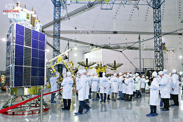
Seminar participants visit the GLONASS production facility. (Photo: Reshetnev)
A United Nations workshop held in Krasnoyarsk, Russia, May 18-22 focused on sharing GNSS in various countries, as well as training in GNSS technologies.
The five-day workshop, organized jointly by the United Nations Office for Outer Space Affairs and the Russian Federal Space Agency (Roscosmos), sought to address the use of GNSS for various applications that can provide sustainable social and economic benefits, in particular for developing countries.
Titled “The use of global navigation satellite systems, GNSS/GLONASS,” the meeting was hosted by the Reshetnev Information Satellite Systems Joint Stock Company. This is the first time the workshop was held in Russia.
A key topic of discussion was the sharing of GNSS in different countries, according to the Reshetnev website. Particular attention was paid to training in the use of satellite navigation, with the most important outcome a proposal to create, under the auspices of the Reshetnev company, an international education center in the use of satellite navigation. The center will cooperate with the UN office in Vienna, as well as regional centers in Morocco, Nigeria, India, Brazil and China.
The seminar was held in nine sections. The sections considered topics such as the formation and development of GNSS, GNSS infrastructure, and national projects on the use of satellite navigation. Representatives from more than 20 countries in Asia, Africa, Europe, North and Latin America shared their experiences implementing GNSS services and spoke about the real and projected benefits of using these technologies for social and economic development.
During the seminar, participants visited the MFReshetnev satellite production company responsible for the space segment of GLONASS in Russia. Guests were shown current and future GLONASS-M and GLONASS-K satellites, as well as learned about the latest developments for GLONASS.
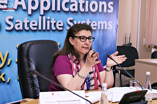
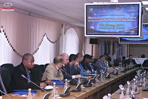
UN representative Sharafat Gadimova summarizes the workshop. (Photo: Reshetnev)Participants discuss the uses of satellite navigation. (Photo: Reshetnev)
Map of sediment thickness in state waters offshore of San Francisco. About 21,000 years ago, sea level in this area was about 125 m lower and the shelf offshore San Francisco was an emergent land surface. At that time, the Sacramento River drained through the Golden Gate and eroded a valley (“the San Francisco paleovalley”) that was filled with sediment during subsequent sea-level rise. The thickest young sediment in the region occurs in the “San Andreas graben,” a basin that formed by crustal down dropping along the offshore section of the San Andreas fault. There is very little sediment on the shelf offshore of southern Ocean Beach (a pattern that extends south to Pescadero), a factor important for understanding and forecasting coastal erosion in this area.
Three new sets of maps detail the offshore bathymetry, habitats, geology and submarine environment of the seafloor off the coast of San Francisco, Drakes Bay and Tomales Point.
Critical for resource managers, the maps are part of the California Seafloor and Coastal Mapping Program, a series of maps published by the U.S. Geological Survey with support from the California Ocean Protection Council, NOAA and 15 other state and federal partners. The maps are designed to be used by a large stakeholder community and the public to manage and understand California’s vast and valuable marine resources.
“OPC is proud to be a partner in this interagency effort,” said California’s Secretary for Natural Resources and OPC Chair John Laird. “These maps are critical to the state’s innovative approach to coastal resource management. USGS’s products form the foundation for assessing the performance of our Marine Protected Area network and preparing for climate change impacts such as sea-level rise.”
“NOAA is pleased to be partnering in this integrated ocean and coastal mapping project. By working with partners from across federal, state, academic, and private sectors, we are able to combine data resources and maximize our efficiency in applying a ‘map once, use many times’ approach that benefits all,” said Rear Admiral Gerd F. Glang, director NOAA’s office of coast survey.
The program was initiated seven years ago with the goal of comprehensively surveying and mapping all of California’s state waters. The vision was tremendously ambitious — comparable mapping on this scale has not been attempted anywhere else in the world, the USGS said. Each of the three publications includes 10 map sheets, a pamphlet and a digital data catalog.
The maps and mapping data have a large range of applications. They provide:
a foundation for assessing marine protected areas and habitats;
baselines for monitoring coastal change and sea-level-rise impacts;
critical input data for modeling and mitigation of coastal flooding;
a framework for understanding coastal erosion and developing regional sediment management plans;
contributions to earthquake and tsunami hazard assessments;
more accurate maps for safer navigation;
and essential information for planning, siting, or removing offshore infrastructure.
The new “Offshore of San Francisco” maps document the complex submarine environments along the inlet to San Francisco Bay formed by strong tidal currents, including spectacular sand waves, a deep scour pool beneath the Golden Gate, and the dynamic offshore San Francisco mouth bar and “Potato Patch” shoal.
Sediment distribution maps reveal only a thin sediment cover offshore of the Ocean Beach (San Francisco) erosional hotspot (a pattern extending south to San Gregorio), indicating that today’s present coastal erosion will be a continuing problem, likely to be exacerbated by continuing sea-level rise.
Geologic maps incorporating subsurface data document the location and geometry of the San Andreas, San Gregorio and Point Reyes fault systems, and show how their interactions led to uplift of Point Reyes and development of a deep sediment-filled basin.
The Drakes Bay and Vicinity, and Offshore of Tomales Point maps reveal the diverse and complex range of seafloor habitats typical of the California coast, ranging from the rugged granitic bedrock along the high-energy west coast of Point Reyes, to smooth sand and mud in the more protected Drakes Bay environment that includes the Point Reyes State Marine Reserve.
“There is a ‘WOW!’ factor to the new high-resolution datasets and maps,” said Sam Johnson, the USGS project lead. “They’re allowing scientists to pose new questions and are having a significant role in stimulating research. We’re also seeing a positive impact on public education and awareness.”
To date, 12 map sets and catalogs have been published. Ten additional map sets are now being formatted for publication, which will complete coverage in the Santa Barbara Channel (Oxnard to Gaviota) and from Marina northward to beyond the Russian River.
The maps are created through the collection, integration, interpretation, and visualization of swath sonar data, acoustic backscatter, seafloor video, seafloor photography, high-resolution seismic-reflection profiles, and bottom-sediment sampling data.
Map of offshore sediment thickness in State Waters between Drakes Bay and Salt Point, north of the Russian River. The thickest sediment in the region occurs offshore of the Russian River, and in a large bar along the south flank of Point Reyes Head. There is a relative lack of offshore sediment between Bodega Head and Point Reyes, where the shelf is characterized by abundant rocky habitat and much of the coastal sediment is trapped in large onshore dune fields.Perspective view looking to the southeast over entrance to San Francisco Bay. Golden Gate Bridge is to left (east) of this view. The large sand-wave field lies within Golden Gate channel, and formed from sediment transported out of the Bay by strong tidal currents. Profile A–A’ shows that the larger bedforms can reach heights of over 7 m and are asymmetrical with steeper sides towards the open coast. A smaller field of sand waves to south near Baker Beach shows the opposite symmetry (steep sides toward the Bay) indicating that the strongest tidal currents in that local area are directed eastward.“Seafloor character” map of the San Francisco Region. This is a type of habitat map that classifies the seafloor based on surface hardness and roughness. Such maps are used in various types of ecosystem assessments and seafloor zoning, such as delineation or monitoring of marine protected areas.Bathymetry bounding Tomales Point. Rugged and massive granite outcrops extend offshore from Tomales Point to water depths of as much as 60 meters. Offshore sedimentary rock outcrops (lower left part of image) form distinctive “ribs” on the seafloor and have a notably different appearance. There is minimal sediment on this part of the California shelf because the watersheds draining the west flank of Tomales Point are very small and because Tomales Point and Tomales Bay block sediment transport from the north. Rocky-shelf outcrops and rubble are excellent habitats for rockfish and lingcod, recreationally and commercially important species. Tomales Bay, approximately 20-km long and 1- to 2-km wide, formed along a submerged portion of the San Andreas Fault (very shallow water depths preclude collection of high-resolution bathymetric data at the mouth of Tomales Bay).
Exelis, UrsaNav, the Department of Homeland Security’s Science and Technology Directorate (DHS S&T), and the U.S. Coast Guard have entered into a cooperative research and development agreement (CRADA) for testing and demonstration at former Loran-C sites.
The team will evaluate eLoran as a potential complementary system to GPS. The capabilities and potential utilization methods of eLoran will be explored in depth to identify all strengths, capacities, and potential vulnerabilities of the technology.
The sites are the legacy ground-based radio navigation infrastructure of the decommissioned Loran-C service that could be retained and upgraded to provide eLoran low frequency service.
Under the CRADA, Exelis will use the former Loran-C assets to put eLoran signals in space for research, test and demonstration of the ability of eLoran to meet precise positioning, navigation and timing (PNT) requirements of government and privately-owned critical infrastructure. The first station Exelis will broadcast from is located in Wildwood, N.J. The broadcast will provide a usable signal at a range up to 1,000 miles.
“eLoran is an ideal technology to complement GPS for critical, resilient and assured PNT,” said Ed Sayadian, vice president of Civil & Aerospace Systems for Exelis. “eLoran is a difficult to disrupt technology that offers PNT and wide area broadcast data capabilities indoors, in underground locations and other GPS-denied environments.”
“A preponderance of government, academic, and industry reports have concluded that eLoran is the best independent, multi-modal solution to provide assured PNT as a complement to GPS,” said Chuck Schue, president and CEO of UrsaNav.
Exelis and UrsaNav have entered into this CRADA because they believe that low frequency signals, such as eLORAN, operate independently of GPS signals and can provide alternative timing, either standalone, or as a component of a PNT service. Exelis also believes that as a result of its wealth of experience in its PNT portfolio, that there are many civil and defense applications that require precise time and/or position in GPS-denied environments. Examples include radio frequency interference, both intentional and unintentional; signal attenuation from heavy forest canopy, terrain or buildings; and indoor and underground locations.
As digital producer for Geospatial Solutions, I spent three days this month covering Unmanned Systems 2015, the huge show hosted by the Association for Unmanned Vehicle Systems International (AUVSI). This was definitely the show at which I gathered the most news and footage of exciting UAV/UAS applications in geospatial technology.
Let’s meet the experts responsible for developing high-altitude color and infrared imagery gathering of a city-sized area, a lower altitude quadcopter for surveying and mapping and a small vertical take-off and landing aircraft developed for use by warfighters that is now ready for first responders and others in small, cluttered, urban environments, giving them an eye-in-the-sky in just minutes.
From the chipset level to fully-featured aerial survey platforms to processing software, AUVSI had it all.
Intro to AUVSI’s Unmanned Systems 2015
The Association for Unmanned Vehicle Systems International’s (AUVSI’s) Unmanned Systems 2015 show, held May 4-7 in Atlanta, convened a global community of commercial and defense leaders in intelligent robotics, drones and unmanned systems.
CEA Research: UAS Could Reach 1M U.S. Flights a Day in 20 Years
The United States will reach one million UAS flights per day within the next 20 years, given the right regulatory environment, according to new economic research from the Consumer Electronics Association.
Exelis Showcases CorvusEye at AUVSI 2015
CorvusEye 1500 is one of the programs Exelis featured at AUVSI 2015. From an altitude of 15,000 feet, CorvusEye 1500 provides color and infrared imagery of a city-sized area unavailable with comparable airborne systems. Bernard Brower, product manager for Exelis, shows us how users work with the real-time analytics and processed data to search for vehicle tracks based on location and time.
Trimble Details New OEM Module at AUVSI 2015
Akshay Bandiwdekar of Trimble Integrated Technologies details the company’s BD935-INS module that features precision GNSS with an integrated 3-D Micro-Electro-Mechanical Systems (MEMS) inertial sensor package. As part of Trimble’s GNSS OEM portfolio, the new compact module augments real-time precise positioning with 3-D orientation.
Septentrio Launches AsteRx-m UAS Reciever at AUVSI Show
Septentrio’s Jan Van Hees talks about the AsteRx-m UAS, an RTK-accurate GNSS receiver solution specially designed for the drone market. The AsteRx-m UAS provides high-accuracy GNSS positioning with low power consumption, according to Septentrio.
NavtechGPS Showcases GPS, GNSS Products for Unmanned Systems
NavtechGPS CTO Franck Boynton explains how AUVSI 2015 attendees can incorporate GPS and GNSS technology into unmanned projects. NavtechGPS represents nearly 30 leading manufacturers of GPS and GNSS products.
NovAtel Showcases FlexPak6, FlexPak-S Receivers
NovAtel’s Peter Soar talks about the company’s FlexPak6 receiver that houses its OEM628 triple-frequency plus L-Band GNSS receiver board. It has a highly configurable interface to ensure precise positioning for UAV applications. Soar explains that its “sister unit,” the FlexPak-S, contains a real-time kinematic GPS receiver with an L-3 XFACTOR Selective Availability Anti Spoofing Module (SAASM). The two receivers are both the same size and fit.
Lockheed Martin Displays K-MAX Cargo UAS Helicopter at AUVSI Show
Lockheed Martin Corporation and Kaman Aerospace Corporation transformed Kaman’s K-MAX power lift helicopter into an unmanned aircraft system capable of autonomous or remote controlled cargo delivery. Jon McMillen explains that its mission for the last three years has been to resupply battlefield cargo for the U.S. military in Afghanistan. McMillen says another possible application for K-MAX is firefighting.
NavCom Technology Offers Navigation and Positioning Capabilities for UAS
NavCom Technology’s Jim Williams explains the precise positioning and navigation solutions offered by the company for UAS. NavCom offers GNSS aerial antennas, RTK positioning and its StarFire global satellite-based augmentation system (GSBAS).
Maxtena Displays L1/L2 GPS Antennas for Use in UAS
Stani Licul, CEO of Maxena, displays some of its antennas for use in UAS. Maxtena’s active rugged antenna is designed for L1/L2 GPS and GLONASS bands for GNSS satellite and RTK applications.
Spirent Federal Systems GSS9000 GPS/GNSS Constellation Simulator
Jeff Martin of Spirent Federal Systems talks about how its GSS9000 simulator can help with UAS development. The GSS9000 simulator supports multi-system, multi-constellation GNSS testing for UAS.
NovAtel Talks GPS Anti-Jam Technology for Use in UAVs
NovAtel’s Peter Soar shares on the company’s GAJT (“Gadget”), a single unit GPS anti-jam antenna for use in UAVs. GAJT nullifies jammers, ensuring satellite signals necessary to compute position and time are always available.
Marty Apa, chief engineer for Exelis’ Integrated Electronic Warfare Systems, shows Geospatial Solutions the Disruptor SRx. The Disruptor SRx electronic warfare technology is small enough to fit into UAS. It also has the ability to switch between multiple functions in real time.
Geomatics USA’s Ahmed Mohamed showcases a UAS that uses the company’s GPS technology to take off and land quadcopters from its structure. Geomatics USA also offers its G-AT: Active Target for surveying and mapping.
Lockheed Martin Corporation Demos Indago UAS at AUVSI Show
Lockheed Martin demonstrates its Indago UAS. The Indago payload system features a quick disconnect adapter which allows the operator to choose the appropriate payload for the mission, according to Lockheed Martin. The payloads are available for a variety of different applications, including agricultural, mapping, inspection and ISR.
Exelis’ Symphony RangeVue Offers Web-Hosted Aircraft Surveillance Information
Christian Ramsey, UAS program manager for Exelis, explains that the Symphony RangeVue enables UAS operators and test-range personnel to have access to both real-time and historical aircraft surveillance information via a web-hosted platform, helping to manage mission operations across multiple locations. Symphony RangeVue can be used as command center decision support and post-event analysis tool, or in the field as a sense-and-avoid addition to UAS ground control stations. Flexible geofencing tools alert operators when a UAS approaches airspace boundaries or other aircraft are in the vicinity.
Spectracom Shows Off Rugged Product Line at AUVSI Show
Spectracom displayed its precise positioning, navigation and timing solutions that leverage GPS/GNSS signals at AUVSI 2015. Capabilities for unmanned aerial systems (UAS) include precision references, signal generation, reception, synchronization, distribution, test/validation, simulation, integration, interference, detection/mitigation, real-time embedded and technical/support services.
Jim Lau with Racelogic details the company’s GNSS Simulator and VBOX Speed Sensor IMU. VOBX is a 100-Hz dual-antenna GPS/GLONASS speed sensor (VBSSISL) that combines signals from an integrated inertial measurement unit with those from GPS to provide smoother output data even when satellite reception is interrupted.
Next year’s show has been branded XPONENTIAL 2016, “An AUVSI Experience,” and will be held in New Orleans, May 2–5. See you there!
Ship management company EuroShip Services Ltd. has installed eLoran as a backup to GPS to ensure the safety of its vessels operating off the coast of the United Kingdom.
The trial installation may lead to implementation across the full fleet of 16 vessels managed by Euroship, working routes in Northern Europe. The land-based radio navigation system is intended to seamlessly take over in the event of a GPS outage. EuroShip plans to simulate GPS outages to test eLoran provision of position, navigation and timing data automatically.
Euroship Services is one of the first ship managers to trial eLoran as a back-up to its GNSS. The company manages vessels owned by Cobelfret. They are mostly shortsea vessels, operating in and out of port, frequently in congested waters and with bridge teams that rely heavily on bridge systems for situational awareness.
Euroship managing director Frank Davies told Lloyd’s List that the company has so far been impressed with the first trial system on one of the company’s vessels. He said that with the company’s vessels entering and exiting large European ports, crews have even noticed distorted GPS signals while going under bridges.
Signals from both Galileo satellites launched March 27 are now transmitting signals.
Researchers at Université de Liège and at the German Aerospace Center (Deutsches Zentrum für Luft- und Raumfahrt, or DLR) reported on May 21 that the first of the full-operational-capability (FOC) satellites had begun transmitting standard L-band signals. The satellite, designated Galileo 8, is using pseudorandom-noise-code identifier 22.
The first E1 and E5 signals from Galileo 8 were received at an International GNSS Service Multi-GNSS Experiment tracking station in Windhoek, Namibia, at about 11:32 UTC on May 21. The satellite’s signals were subsequently tracked by a station in Wettzell, Germany, and then by others.
The other satellite, Galileo 7, began transmitting standard L-band signals on May 25. The first E1 and E5 signals from Galileo 7 were received around 17:00 UTC. The satellite is using PRN code 26.
The signals will be set unhealthy for use until satellite commissioning is completed.
Galileo 7 is also known as GSAT0203, FOC-FM3 and as NORAD object 40544. Galileo 8 is also designated GSAT0204, FOC-FM4 and NORAD object 40545.
As hundreds of thousands of tourists flock to the Washington, D.C., area for their summer vacations and residents join them on city streets and at public gatherings, the Federal Aviation Administration has a clear message for everyone: Leave Your Drone at Home.
The FAA has announced a public outreach campaign for the region around Washington, D.C., to reinforce the message that the city itself, and communities within a 15-mile radius of Ronald Reagan Washington National Airport, are a “No Drone Zone.” The effort includes furnishing outreach materials to federal, state and local partners around the National Capital Region. The agency wants to ensure residents and tourists all understand that flying an unmanned aircraft in this area for any purpose is against the law.
The push follows two incidents when drones entered the no-fly zone around the White House. The most recent was on May 14.
Rules put in place after the 9/11 attacks establish “national defense airspace” over the D.C. area and limit aircraft operations — including unmanned aircraft — to those with an FAA and Transportation Security Administration authorization. Violators may face stiff fines and criminal penalties.
The bottom line: Enjoy your visit to the nation’s capital. Bring your family, your cameras and plenty of sunscreen. Just don’t bring your drone.
This map depicts the proposed body of work for 3DEP in Fiscal Year 2015. The BAA awards will add more than 95,000 square miles of 3DEP quality LiDAR data to the national database.
The U.S. Geological Survey National Geospatial Program is developing the 3D Elevation Program (3DEP) to respond to growing needs for high-quality topographic data and for a wide range of other three-dimensional representations of the nation’s natural and constructed features.
To expand awareness of 3DEP status and plans, as well as provide an open forum for 3DEP stakeholders to communicate and coordinate potential Broad Agency Announcement (BAA) proposals, the USGS is offering numerous state and regional coordination workshops.
The primary goal of 3DEP is to systematically collect 3D elevation data in the form of light detection and ranging (LiDAR) data over the conterminous United States, Hawaii, and the U.S. territories, with data acquired over an eight-year period. Interferometric synthetic aperture radar (ifsar) data will be acquired for Alaska, where cloud cover and remote locations preclude the use of LiDAR in much of the state.
The 3DEP initiative is based on the results of the National Enhanced Elevation Assessment that documented more than 600 business uses across 34 federal agencies, all 50 states, selected local government and tribal offices, and private and nonprofit organizations. A fully funded and implemented 3DEP would provide more than $690 million annually in new benefits to government entities, the private sector and citizens.
3DEP is a “Call for Action” because no one entity can accomplish it independently. 3DEP presents an opportunity for collaboration between all levels of government to leverage the services and expertise of private-sector mapping firms that acquire the data, and to create jobs.
“When partners work together, they can achieve efficiencies and lower costs so that 3DEP can become a reality,” the USGS said in a press release. “When 3D elevation data are available to everyone, new innovations will occur in forest resource management, alternative energy, agriculture, and other industries for years to come,” the USGS said.
Esri has released ArcGIS 10.3.1, bringing new capabilities.
Smart Mapping is an innovative approach for creating maps that is available through ArcGIS Online. Users can quickly style the features of a map to create useful and visually stunning maps every time, Esri said.
3D Web Scenes allow users to view, create, and share 3D web scenes in a browser. Available in ArcGIS for Server and Portal for ArcGIS, users can share these scenes within their own infrastructure or make them public.
With the ArcGIS 10.3.1 release, ArcGIS for Server with Portal for ArcGIS can now host web scenes and layers that include multipatch–based 3D models and symbology, such as photo-realistic buildings, trees, and visibility domes.
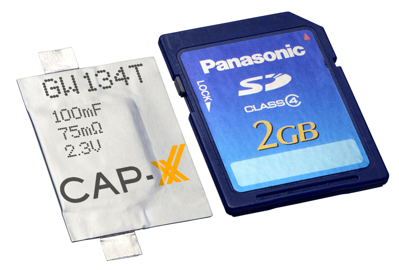
Cap-XX Thinline Supercapacitor shown with an SD card.
Cap-XX, developer of flat supercapacitors for burst and back-up power in space-constrained electronic devices, has launched its Thinline series of single-cell supercapacitors. The thin (0.6-mm) supercapacitors were developed to address the size, weight and cost challenges of designing thin, sometimes disposable electronic devices for the Internet of Things (IoT).
Examples include wearables (medical, fitness and health monitors, smartwatches, drug delivery systems), portables (active credit cards, smartphones, RFID tags), and connected electronics (smart homes and smart buildings, electronic shelf labels, wireless sensor networks).
To reduce thickness and manufacturing costs, CAP-XX increased the power and energy density in its electrode materials to deliver equivalent performance in about half the volume, and eliminated the folded edges and copper terminals that contribute to thickness in its standard line supercapacitors. (For comparison, CAP-XX’s thinnest traditional single-cell supercapacitor is 1.10 mm.)
Cap-XX Thinline supercapacitors support power requirements in IoT devices including GPS acquisition, wireless communication (Bluetooth, Bluetooth Smart, Zigbee, Z-Wave, Ant, active RFID), electronic paper and OLED displays, haptic or tactile feedback, vibration alerts, and injection or inhalation system delivery.
Cap-XX supercapacitors benefit from a nanotechnology construction that stores electrical charge in engineered carbon electrodes on aluminium foil, to minimize resistance and maximize capacitance. The electrode construction packs the highest energy and power densities possible into thin, prismatic packages, the company said.
Supercapacitors can handle peak power events, supporting batteries and energy harvesters configured to provide low-power current at maximum efficiency. This architecture allows designers to use smaller, cheaper, low-power batteries and extend their run-time and cycle life, or use intermittent ambient energy sources such as solar photovoltaic. Supercapacitors also enable ultra-quick device charging and wireless power transfer, and provide the backup needed for graceful shutdown and “last gasp” transmissions in mission-critical applications.
The Thinline idea was born while working with a customer designing a disposable insulin pump. “We figured out how to eliminate materials and change some processes to reduce costs and thickness,” explained Anthony Kongats, Cap-XX CEO.
Thinline works with thin-film, solid-state, and other low-power batteries such as coin cells/button cells, energy harvesting modules (solar, vibration/kinetic, RF, and other ambient energy sources), as well as inductive/wireless and cable/cradle fast-charging systems.
Features of Thinline include:
Extremely thin, flexible packaging from 0.6mm (600µm) thick
Best-in-class power density and power output (up to 117kW / litre)
Ultra-low resistance, even at low temperatures (ESR from 16mΩ, 2x nominal at -40°C)
Excellent energy storage to support ambient/intermittent sources (up to 0.8Wh / litre)
High cell voltages to facilitate integration with primary batteries (up to 2.75V continuous)
Wide operating temperature range (from -40°C to +85°C)
Very low leakage current to maximize battery life and minimize losses (typically < 1µA)
Virtually unlimited charge-discharge cycle life
Cap-XX Thinline supercapacitors are available in three footprints:
“A” series: 19.5mm x 20.0mm x 0.6 – 0.9mm thick, 60 – 180 mF, 45 – 200 mΩ
“W” series: 28.0mm x 20.2mm x 0.6 – 0.9mm thick, 100 – 300 mF, 24 – 120 mΩ
“S” series: 39.0mm x 20.2mm x 0.6 – 0.9mm thick, 180 – 540 mF, 16 – 75 mΩ
Suggested retail price for all 0.6-mm cells is less than US$1 in large volumes. The 0.7 mm and 0.9 mm cells in each series have higher C/lower ESR and cost slightly more. All parts are available in a 2.3V / 70°C, or 2.75V / 85°C configuration. They can be assembled by soldering or welding (ultrasonic, laser or spot).