Topcon Positioning Group is expanding the TopNETlive GNSS reference station network into Latin America. In conjunction with hosting partners, new service will be provided in Mexico, Peru, the Dominican Republic, Bolivia, Guatemala, Colombia and Panama.
TopNETlive is designed to deliver high-accuracy GNSS correction data to rovers for surveying, construction, GIS mapping and agricultural applications.
Partners in the Latin America expansion include TTQ of Monterrey, Geomatic Instruments Corporation, Caribbean Positioning System, Mertind, GYFSA and GeoSystem.
“The growth of the network into Latin America through these strong partnerships clearly demonstrates the Topcon commitment to grow TopNETlive and provide quality service to more positioning professionals globally,” said Jonathan Ball, senior manager for the Topcon network business. “Our hosting partners provide outstanding support, training and service to their customers and the addition of the TopNETlive reference stations will allow them to expand their operations by offering real-time network correction data.”
Topcon dealers will host TopNETlive throughout the various regions, which include: TTQ of Monterrey for Mexico, Geomatic Instruments Corporation in the Peruvian market, Caribbean Positioning System in the Dominican Republic area, Mertind Ltda in Bolivia, GYFSA in Guatemala, and Columbia-based GeoSystem will host the network throughout Colombia and Panama.
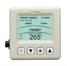
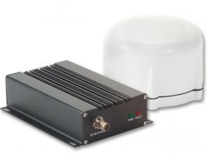
KVH Industries Inc. has received a $1.5 million contract for the delivery of tactical navigation systems for use by an international military customer in an armored vehicle application. A variant of KVH’s TACNAV TLS and TACNAV Light, the system is designed to help military vehicle crews maintain 100% situational awareness. The hardware shipments for this order are expected to be made in 2015. Program management and engineering services will be provided as part of this order.
“KVH’s TACNAV navigation solution is an important tool for U.S. and allied warfighters, providing precision navigation as well as coordination of vehicles in critical situations,” said Dan Conway, executive vice president of KVH’s guidance and stabilization group. “The system serves as a crucial resource for navigation and battle management, keeping soldiers safe and out of harm’s way wherever they travel. This new order reaffirms the value of KVH’s TACNAV products for international militaries, and adds to our backlog for the year.”
The TACNAV TLS by KVH Industries.
All of KVH’s TACNAV military vehicle navigation systems provide unjammable precision navigation, heading, and pointing data for vehicle drivers, crews and commanders, KVH Industries said. TACNAV can also serve as a heading and position source for situational awareness.
The TACNAV system ordered combines characteristics of TACNAV TLS and TACNAV Light, and features a compact design, continuous heading and pointing data output, and a flexible architecture that allows it to function as either a standalone navigation module or as the heart of an expanded, multifunctional TACNAV system. The system is designed to integrate with battle management systems and is a vital component for effective battlefield management, KVH Industries said.
TACNAV systems are in use by the U.S. Army and Marine Corps, as well as many allied customers including Canada, Sweden, Great Britain, France, Germany, Spain, Egypt, Botswana, Australia, New Zealand, Saudi Arabia, Taiwan, Romania, Poland, Turkey, Malaysia, Switzerland, South Korea, Singapore, Brazil and Italy.
Jamming Signals Criminal Activity in Intermodal Ports
By Logan Scott
More than 25 million containers pass through U.S. intermodal ports every year, with port operations valued at more than $1 billion per day. Measured in 20-foot equivalent units (TEU), the World Bank reports that worldwide, more than 600 million TEU passed through intermodal ports in 2012: 155 million through Chinese ports, 95 million through the EU ports and 43 million through U.S. ports.
The Port of Long Beach alone handled 6,820,806 TEU in 2014. GPS is a central component of automated port operations, but because GPS is widely used in asset tracking and monitoring, it has also become a target for denial-of-service attacks. If we look to the history of computer security, the initial attacks were mostly nuisances, but as criminals figured out how to monetize attacks, the attacks became more damaging, more sophisticated and more profitable.
In January, the U.S. Coast Guard held a public meeting on Maritime Cybersecurity Standards at Department of Transportation headquarters in Washington, D.C. Brett Rouzer, chief of Maritime Critical Infrastructure and Key Resources Protection, Coast Guard Cyber Command, described how a major East Coast intermodal shipping facility was degraded by a GPS disruption for more than seven hours. Two ship-to-shore cranes ceased operation due to loss of position, and two others were degraded. Ports are highly automated; ship-to-shore cranes are just one of the container-handling systems critically reliant on GPS. Fully automated ports providing services for unmanned container ships, trucks and trains lie within the realm of feasibility in the near future.
Rouzer did not specify the motivates for the disruption, how the attack was mounted, or if the shipping facility was even the intended target of the attack (I suspect it was not). Jamming is not a highly selective process, and it can affect numerous unintended targets.
In June 2014, I reported to the PNT Advisory Board on how every third or fourth truck on Highway 30B near Portland (Oregon) International Airport was radiating at or near the GPS L1 frequency. This highway leads to several nearby Port of Portland intermodal terminals west of the airport. The Federal Bureau of Investigation recently reported that “In 46 reported incidents, the thieves placed one or more GPS jammers in cargo containers with stolen automobiles” (italics mine). High-end automobiles command premium prices in foreign markets and are stolen and shipped out of the country within hours, usually via intermodal container. Active jammers can affect not only the automobile’s GPS tracker, but also trackers on other containers, ship’s navigation systems, straddle carriers and ship-to-shore cranes. Again, jamming is not selective.
Of particular note as cited above, criminals are beginning to use multiple jammers. Car theft rings are not unique in this. According to the Pharmaceutical Cargo Security Coalition in July 2014, “a tractor and trailer hauling $2 million worth of pharmaceutical products was stolen from a truck stop in Cartersville, Georgia, with the thieves deploying two separate GSM jammers.” The criminal’s motivation is that tracking devices can be hard to find and disable; just because you found one doesn’t mean that there isn’t another. The use of multiple jammers in criminal enterprise is indicative of a threat escalation where bad actors are seeking higher effect. This could lead to higher jamming powers and so on; and also more collateral damage.
Response
What is a correct and measured response to threats against navigation and timing? The key is to be on the lookout for emerging threats and to have a flexible response. Early detection usually yields a more effective and lower cost response; witness Ebola and ISIS. Following a public health model would seem to offer better prospects for protecting access to PNT. To this end, I would argue that situational awareness is the first important step.
One of the most striking comments that Sarah Mahmood (DHS) made at last June’s PNT Advisory Board meeting was about how backup systems are often not activated or used because the GPS receiver fails to recognize that there is a problem. As we move towards resilient PNT architectures, one of the most critical needs is to be able to distinguish good signals from bad signals and act accordingly.
Most GNSS receivers already have fairly advanced jamming detection capabilities by virtue of having an automatic gain control. Sudden changes in precorrelation input power levels are not normal and can indicate jamming or RF spoofing. Many GNSS receivers, particularly those that go into embedded mobile applications, also have sophisticated spectrum- and temporal-analysis capabilities, used mainly for diagnostic purposes in looking for interference sources from other components of the device. This same capability can be used in detecting and fingerprinting jammers. We already have the smoke alarms; we must amplify their use and visibility to the wider community of GNSS users and beyond.
Detection
One notable aspect of the port incident was the duration: more than seven hours. Rapidly finding and disabling the jammer was clearly a problem in this case. The old adage is that to find a stationary source (jammer) you need to be moving, and to find a moving source, you need to be stationary. Trucks and trains entering or leaving a port all pass through gates that can act as a simple chokepoint for detecting and finding active jammers. Properly hardened ship-to-shore cranes and straddle carriers can also act as a chokepoint. Straddle carriers used in moving containers around the yard and between modes could be very good at finding stationary jammers.
There are numerous relatively low-cost approaches for finding jammers in support of enforcement actions. One additional point: law enforcement officials need to be better educated as to why they should be interested in jammers; jammers point towards a crime much like smoke points to a fire.
Given the economic criticality of port operations and the concentration of assets (and asset trackers), we may see increased incidence of GPS disruptions. The situation is not critical yet, but it does bear watching. If jamming events increase or it takes too long to find and disable jammers, improved operational resilience will be needed.
Inertial measurement units are already used in many critical applications, but they don’t offer long-duration capability. They drift. Using adaptive arrays in critical equipments is another possibility, but they are not a panacea. Adaptive arrays are physically large, and standard null-steering approaches are not compatible with RTK processing. Precise positioning systems based on GNSS require specialized antenna-receiver designs to achieve a high level of jam resistance.
While I strongly believe eLoran is an urgently needed augmentation for resilient wide area navigation, it is not capable of the centimeter-level precision required for machine control, for example ship-to-shore cranes and straddle carriers.
High-precision local-area positioning systems based on optical systems, RFID and/or Locata-style systems may be the best approach for creating a defense in depth.
And then there is the cybersecurity question, which I will leave for another day.
Note: A video of the Coast Guard meeting is on YouTube. Rouzer’s talk starts at 36:30, with the port jamming incident mentioned at 48:51.
Logan Scott has 35 years of military and civil GPS systems engineering experience. He is a consultant specializing in radio frequency signal processing and waveform design. At Texas Instruments, he pioneered approaches for building high-performance, jamming-resistant digital receivers. He is a co-founder of Lonestar Aerospace, an advanced decision analytics company in Texas. Logan is a Fellow of the Institute of Navigation and holds 37 U.S. patents.
From left: Dennis McCarthy, Wayne Hanson, Ronald Beard and William Klepczynski
By Dennis McCarthy, Wayne Hanson, Ronald Beard and William Klepczynski
Once again we are going to adjust the world’s clocks by one second. This time it will happen on June 30, when we insert another leap second in Coordinated Universal Time (UTC), the standard international time scale. In theory, all UTC clocks should insert a second labeled 23h 59m 60s (the leap second) following one labeled 23h 59m 59s UTC. This is equivalent to having all of the clocks in the world stop for one second at that time.
Are you ready for it?
The last leap second occurred two years ago on June 30, 2012, and the continuation of the process of making these one-second adjustments has stirred a growing controversy over the last few years.
How did the leap second come about — and why do we continue making these sporadic adjustments?
From Sun to Caesium
Historically, it has been easy to make use of the apparently uniform repetition of various astronomical phenomena to measure the passage of time. We’re familiar with the Sun rising and setting, and this regularity provides us a convenient measure of time: the solar day. In recent times until 1960, the average solar day was used as the basis for timekeeping, and if we divide the day into 24 hours, each containing 60 minutes made up of 60 seconds, we can define the second as 1/86,400 of the mean solar day. This meant that the length of the second depended on the Earth’s rate of rotation because it is the rotating Earth that causes the Sun to appear to move across the sky.
In the mid-1930s, astronomers concluded that the Earth did not rotate uniformly as measured by the most precise clocks then available. This causes the duration of a second to vary as the Earth’s rotation rate varies. We now know that a variety of physical phenomena affect the Earth’s rotational speed, and consequently this definition of a second became impractical for applications that require a truly uniform time scale. So, in 1960, the second was redefined in terms of the Earth’s yearly orbital motion around the Sun. The time scale provided by this astronomical phenomenon was called Ephemeris Time (ET), to call attention to the fact that its realization depended on the conventionally adopted positions and motions (that is, the ephemeris) of the Sun (or Moon) that was used in the analyses of the required astronomical observations. The second defined in this manner was called the Ephemeris second.
Although Ephemeris Time does provide a more uniform measure of the duration of a second, it is inconvenient to make the necessary astronomical observations that would be required to maintain a practical time scale for applications that demand high precision. So, in 1967, the second was redefined again, this time in terms of the frequency of an energy level transition in the Caesium atom, which had already been calibrated with respect to Ephemeris Time by using astronomical observations of the Moon’s motion. Caesium frequency standards, by the early ’60s, had become known as reliable, uniform, accurate and precise clocks. The second defined in this way provided, and continues to provide, a uniform standard of time that can easily be measured in a laboratory with greater precision and accuracy than any astronomical phenomena.
Lab Clocks Rule
Although the second defined using the frequency of an atomic energy level transition does provide a unit of time duration that is precise and uniform, it does mean that the passage of time measured in this way is no longer connected to astronomical phenomena. Indeed, with the advent of more accurate observational techniques, astronomers could measure variations in the Earth’s rotation rate by measuring its changing orientation in space and comparing the rate of change with laboratory clocks. They established that among the various variations in the Earth’s rotation rate is the gradual slowing down with respect to a uniform atomic time scale. This deceleration is consistent with theoretical tidal effects and observed terrestrial deglaciation.It is also apparently consistent with ancient observations of solar eclipses, indicating that that this slowing has been going on for thousands of years
As a result, if we were to observe a recurring astronomical event, we would see it happening earlier from day to day. To bring our clock back into agreement with the astronomical event, we would have to add some time to the face of our atomic clock. While astronomers can cope with this situation by applying the appropriate corrections derived from astronomical observations that measure the Earth’s rotation rate, navigators that relied on astronomical observations to determine their positions considered this situation problematic.
When the definition of the second based on the Caesium atom was introduced, it was known that there would be a time varying discrepancy between a clock running at a uniform rate and a theoretical one using a second defined by the Earth’s rotation rate. Starting from 1961, the observed discrepancy was modeled by making small adjustments on the order of a few milliseconds (thousandths of a second) to our clocks at first, and later by making small adjustments to the frequency of the atomic clocks from time to time, usually on an annual basis. This meant that the duration of a second could vary depending on when it was measured.
No More Changes
In 1970 the International Radio Consultative Committee (CCIR and now known as the International Telecommunications Union Radiocommunications Sector, or ITU-R) in collaboration with other international agencies adopted a definition of UTC that did away with any periodic changes to the duration of the second. Instead it was decided that the discrepancy between UTC and the observed rotation angle of the Earth would be accounted for by making one-second adjustments when needed, so that the absolute difference between UTC and the Earth’s rotation angle measured in time units would always be less than 0.9 seconds. A finer correction would also be provided frequently so that the Earth’s rotation angle in time units designed as Universal Time 1 (UT1) could be derived to 0.1 second precision.
It was specified that the one-second adjustments, either positive or negative, were to be made preferably at 23h 59m 59s on the last day of the months of December or June, but could also be made, if necessary, at 23h 59m 59s on the last day of the months of March and September, and further if required at 23h 59m 59s on the last day of any month. The implementation of this definition actually began in 1972, a year in which two leap seconds were introduced.
These one-second adjustments came to be known as “leap” seconds by analogy with the “leap” day inserted in calendars. This definition then fixed the second in UTC to be uniformly established as the international standard atomic second defined by the resonance frequency of Caesium and known as the SI (Système International) second.
Compromise Overcome by GNSS
The introduction of the concept of the leap second was historically a compromise with practitioners of celestial navigation who needed to base their observations on astronomical time to determine their longitude. If UTC doesn’t differ from the observed rotation angle of the Earth by more than a second, navigators could use UTC directly as a substitute without introducing a systematic error greater than a quarter of a mile. However, the routine practice of using celestial navigation has been overcome by the success of Global Navigation Satellite Systems (GNSS), inertial navigation systems, and radar navigation.
In fact, the U.S. Naval Academy stopped including celestial navigation in its curriculum in 1998. In the time span since the introduction of the idea of a leap second, computer networks, wireless telecommunication systems, satellite communications, telephone networks, air traffic control systems and even industrial processes have developed to the point where precise time is an essential component of their successful operation. Users and suppliers of these systems are concerned with the impact of sporadic, essentially unpredictable, one-second adjustments.
Most of these modern systems derive their time using GPS timing receivers. Although the navigational solutions make use of GPS System Time, these receivers provide UTC by means of a broadcast correction that provides the time-varying difference between GPS System Time and UTC. This correction normally provides the varying difference between the two times to less than a microsecond but must also keep track of when a leap second is introduced. As the leap second changes occur sporadically, there may be worries that problems could arise because hardware or software may never have been tested thoroughly for a leap second occurrence. As a result of these concerns, as well as the cost of stopping all of the clocks in the world for one second, the ITU-R has been discussing a possible revision of the definition of UTC by dropping the future use of leap seconds.
Leap or Not Leap?
The question of the future of UTC was raised in 2000 with the suggestion of modifying it to be a continuous timescale without leap seconds. Consideration of this question is still ongoing. The 2012 World Radiocommunication Conference (WRC-12) identified this issue as urgent, requiring further examination by the 2015 World Radiocommunication Conference (WRC-15) “to consider the feasibility of achieving a continuous reference time-scale, whether by the modification of Coordinated Universal Time (UTC) or some other method, and take appropriate action…”.
With the aim of providing adequate technical background for WRC-15 to make an informed decision on this issue, the International Bureau of Weights and Measures (BIPM) and the ITU agreed to organize jointly a workshop on the future of the international time scale. This workshop was held in Geneva, Switzerland, in September 2013. It provided a unique opportunity to present available information on current and possible future precise frequency and time standards, sources and their characteristics, time scales and dissemination systems and different views on the future of UTC.
Contributions to the workshop were specifically invited to ensure that the breadth of the issue would be covered. Included were the relevant international organizations (the International Astronomical Union, the International Earth Rotation and Reference Systems Service, the International Union of Geodesy and Geophysics, the International Organization for Standardization, the International Maritime Organization, the International Civil Aviation Organization, the Union Radio-scientifique Internationale), the providers of GNSS services (GPS, GLONASS, Galileo and BeiDou), the national metrology institutes that realize and maintain local representations of UTC, the ITU member administrations, and the ITU-T and authorities responsible for electronic time services. Information on the workshop, agenda and presentations is available.
Final Decision in November
A special issue of ITU News magazine dedicated to the workshop has also been published; an online version is available. It did not provide a decision on the issues, but rather a forum for issues to be discussed, since there is some controversy over modifying the global reference time scale. The final decision is to be made at the WRC-15 in November when the method for satisfying the feasibility of achieving a continuous time scale will be determined as well as how it would be implemented.
As preparations begin for the June leap second, hardware and software will undergo testing. This process is likely to be repeated for some time to come, even if the decision to eliminate the use of leap seconds in UTC is made. Legacy systems reliant on the use of leap seconds will require an adequate period of time to adapt to any change in the definition of UTC. If the suppression of leap seconds would be decided, it is recommended that a period of time no less than five years be allowed before the Final Acts of the WRC-15 go into effect. So, leap seconds could be with us for some time yet.
Editor’s Note: For an earlier discussion on the leap second by McCarthy and Klepczynski, download the Innovation article “GPS and Leap Seconds: Time to Change?” from the November 1999 issue of GPS World.
Dennis McCarthy is retired, and serves as a contractor with the U. S. Naval Observatory, where he was science advisor, director of the Directorate of Time, and head of the Earth Orientation Department. Internationally, he has served as president of the Commissions on Time, Commission on Earth Orientation, and Division 1 (Fundamental Astronomy) of the International Astronomical Union (IAU). He was also secretary of Commission 5 of the International Association of Geodesy.
Wayne Hanson has been a consultant and president of Time Signal Engineering since his retirement in 2001 as chief of the Time and Frequency Services Group in the Time and Frequency Division of the National Institute of Standards and Technology. He is the U.S. chairman of the International Telecommunication Union – Radiocommunication Sector, Working Party 7A concerned with Time Signal and Frequency Standard Emissions.
Ron Beard is the head of the Advanced Space PNT Branch at the Naval Research Laboratory and International Chairman of ITU-R Working Party 7A, Precise Time and Frequency Broadcast Services. During the early development of GPS in the 1970s, he was the project scientist in the NRL GPS Program Office that developed Navigation Technology Satellites One and Two that operated the first atomic clocks in space.
William Klepczynski is now retired. During his career, he was a consultant to the Institute for Defense Analyses and the head of the Time Service Department of the U.S. Naval Observatory, where he managed the USNO Master Clock, timing operations for GPS and time distribution systems that utilize communications and navigation systems.
Forsberg Services Ltd. has acquired the StarLink product line from Raven Industries. StarLink includes inline amplifiers, coaxial down/up converters and fiber-optic link systems to enable and support extended cable runs for GNSS in navigation and time synchronization applications.
Raven Industries’ Starlink GPS down/up converter makes it possible for long cable runs of up to 450 meters.
“This opportunity provides an excellent addition to complement our range of GNSS products and services,” said Chris Mayne, Forsberg operations director. “We have worked closely with Raven Industries as a distributor of the StarLink products for the last three years and appreciate the opportunity to take the product brand forward with its customary high quality and standards.”
Forsberg Services Ltd. is a European navigation systems integrator and OEM component supplier based in Lancaster, U.K and with offices near Hannover, Germany. The company has strong engineering experience in navigation; specializing in PCB, software and mechanical design to produce unique navigation products for a range of applications and market sectors.
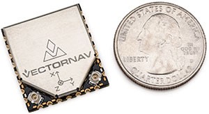
VectorNav Technologies has released a surface mount version of its VN-300 dual-antenna GPS-aided inertial navigation system (GPS/INS). It will be on display at booth 942 at AUVSI’s Unmanned Systems show, held May 5-7 in Atlanta.
Surface Mount Device
The VN-300 surface mount device (SMD) is a miniature MEMS-based inertial navigation module that includes both inertial navigation and GPS-compassing capabilities, which together provide high-accuracy position and velocity in both stationary and moving conditions. With the release of the surface mount version, VectorNav is also announcing the addition of GNSS capability to the full VN-300 product line. The VN-300 SMD completes VectorNav’s line of industrial grade inertial sensors, joining the VN-100 IMU/AHRS and VN-200 GPS/INS surface mount and Rugged modules.
Incorporating the latest MEMS sensor technology, the VN-300 combines 3-axis accelerometers, 3-axis gyros, 3-axis magnetometers, a barometric pressure sensor, two GPS receivers, and a low-power microprocessor into a rugged aluminum enclosure about the size of a matchbox. When in motion, the VN-300 couples the position and velocity measurements from the onboard GPS receivers with measurements from the onboard inertial sensors to provide position, velocity, and attitude estimates of higher accuracies and with better dynamic performance than a standalone GPS receiver or Attitude Heading Reference System (AHRS).
With the release of the surface mount version of the VN-300 the company says its own Rugged is surpassed as the smallest and lightest dual-antenna GPS/INS on the market. The surface mount VN-300 shares the same footprint and form factor with VectorNav’s surface mount VN-100 IMU/AHRS and VN-200 GPS/INS.
“The VN-300 surface mount chip is an achievement that combines the best of our expertise in inertial navigation algorithms and our innovative approach to miniaturizing embedded navigation sensors. There simply is no other product like it on the market,” said ohn Brashear, VectorNav’s president. “The VN-300 SMD completes our Industrial Series of inertial navigation sensors and paves the way for the expansion of our product lines into new markets and applications.”
The VN-300 is ideal for industrial and military applications that are size, weight, power and cost (SWAP-C) constrained, or that require an inertial navigation solution under both static and dynamic operating conditions, especially in environments with unreliable magnetic heading such as fixed-wing and multirotor UAVs, aerostats and other tethered UAVs, gimbaled camera systems onboard helicopters and multirotors, antenna systems onboard ground vehicles and marine vessels, weapons training and warfare simulation, and direct surveying.
New GNSS Capability
With the release of the surface mount version, VectorNav is also announcing the addition of GNSS capability to the full VN-300 product line.
The addition of GNSS capability now enables the VN-300 product line to include measurements from satellites in the GLONASS constellation in addition to GPS. These additional measurements provide greater tracking reliability and improved VN-300 performance in urban canyons and reduced visibility conditions.
Firmware Update
VectorNav is also announcing the release of a new firmware update for the VN-300 that improves the overall accuracy and time to acquisition of the GPS-compass feature. The new firmware also includes logic that enables the VN-300 to intelligently and seamlessly transition between magnetic heading (AHRS) mode, to INS operation in dynamic conditions and GPS-compass in static conditions, without requiring input from the user.
U.S. Transportation Secretary Anthony Foxx today announced a significant NextGen milestone with the completion of En Route Automation Modernization (ERAM), a highly advanced computer system used by air traffic controllers to safely manage high-altitude traffic.
ERAM was designed to be the operating platform for NextGen technologies, including the Automatic Dependent Surveillance-Broadcast (ADS-B) system. ADS-B transmits information about altitude, airspeed and location derived through GPS from an equipped aircraft to ground stations and to other equipped aircraft in the vicinity. Air traffic controllers use the information to “see” participating aircraft in real time with the goal of improving traffic management.
“Looking at the future of air travel, we know that there will be more planes in our skies and more people in our airports, and in order to meet this challenge we must integrate cutting-edge technology into our aviation system,” said Secretary Foxx. “ERAM is a major step forward in our relentless efforts to develop and implement NextGen. With this new technology, passengers will be able to get to their destinations, faster, safer, and have a smoother ride — all while burning less fuel to get there.”
ERAM is the backbone of operations at 20 of the Federal Aviation Administration’s (FAA’s) en route air traffic control centers. The system, a crucial foundation for NextGen, drives display screens used by air traffic controllers to safely manage and separate aircraft.
“ERAM gives us a big boost in technological horsepower over the system it replaces,” said FAA Administrator Michael Huerta. “This computer system enables each controller to handle more aircraft over a larger area, resulting in increased safety, capacity, and efficiency.”
The first ERAM system went online at Salt Lake City Center in March 2012. The final installation was completed last month at New York Center.
ERAM uses nearly two million lines of computer code to process critical data for controllers, including aircraft identity, altitude, speed, and flight path. The system almost doubles the number of flights that can be tracked and displayed to controllers.
Other NextGen technologies include:
Automatic Dependent Surveillance-Broadcast (ADS-B): The FAA is moving steadily toward replacing the old system of ground-based radars to track aircraft with one that relies on satellite-based technologies, including GPS. ERAM already receives information from aircraft equipped with ADS-B and displays that data on controllers’ screens. This technology has made it possible for controllers to provide radar-like separation to aircraft that previously operated in areas where no radar is available, such as the Gulf of Mexico and large parts of Alaska. ADS-B will replace radar as the primary means of tracking aircraft by 2020.
Performance Based Navigation (PBN): Controllers are already using ERAM to make use of Performance Based Navigation (PBN) procedures that enable controllers and flight crews to know exactly when to reduce the thrust on aircraft, allowing them to descend from cruising altitude to the runway with the engines set at idle power, saving on flying time and fuel consumption.
Data Comm: To reduce congestion on radio frequencies, the FAA and the aviation industry continue to develop Data Comm, which will allow controllers and pilots to communicate by direct digital link rather than voice, similar to text messaging. ERAM is already equipped to handle this technology.
Secretary Foxx and Administrator Huerta attributed the success of the development and installation of ERAM to the collaboration between FAA management and labor, including the National Air Traffic Controllers Association (NATCA) and the Professional Aviation Safety Specialists (PASS). This collaborative process is now a blueprint that will be applied to the rollout of future technologies.
UAV Solutions will display its new fixed-wing unmanned aerial systems (UAS) at AUVSI’s Unmanned Systems 2015 show, to be held May 5-7 in Atlanta.
In booth 1109 the company will introduce the Talon 120LE, a lightweight hand-launched air vehicle, and the Sidewinder, a high altitude, multi-fuel, intelligence, surveillance and reconnaissance (ISR) asset. The Intruder UAS, a multiple intelligence gathering platform with a gross take-off weight of 850 pounds, will be located in booth 2303.
With a wingspan of 12.5 feet, the Talon 120LE is a 16-pound electric UAS that may fly for nearly 2.5 hours. The system was created with open architecture software and hardware components for future flexibility. The company recommends the Talon 120LE for inspecting crops, surveilling power lines or conducting search and rescue missions. Its payload capacity is 2.5 pounds.
The jet powered Sidewinder UAS flies at high altitudes and operates in a low vibration environment ideal for ISR payloads. The Sidewinder can use various heavy fuels including diesel, kerosene and Jet A. It has a wingspan of 16 feet and a payload capacity of 10 pounds.
UAV Solutions’ new Intruder is capable of operating at higher density altitudes. It also is able to collect information via satellite communication, signals intelligence, communications intelligence and imagery intelligence. It has retractable landing gear, and the agnostic center-of-gravity mounted payload location accommodates up to 100 pounds.
Along with the UAS the company is showing, it also will feature its multi rotor UAS — Phoenix 60, Phoenix 30 and Phoenix 15 – as well as the Dragon View camera sensor.
Dragon View sensors can be integrated onto unmanned aerial vehicles (UAVs), antenna towers, buildings or other structures to provide day and thermal imagery, video recordings, object tracking and geolocation data. The sensors are lightweight, mechanically and digitally stabilized gimbals with electro-optical and infrared cameras.
They also can easily be mounted onto UAVs, antenna towers and other structures for police organizations.
Skip Miller, UASUSA’s founder and CEO, stands with with the Tempest ET.
UASUSA will unveil its payload advancements in booth 631 at AUVSI’s Unmanned Systems 2015, held May 5-7 in Atlanta.
The new Trimble RTK high-accuracy GPS positioning system will be available through UASUSA. It covers up to 2,300 acres per flight for photo mosaic and mapping missions with manufacturer specified sub-centimeter accuracy.
UASUSA also modified its leading aircraft, the Tempest, to create the Tempest ET. The new aircraft has added payload storage interchangeable in the wing tip extensions, yet still offers the same level of stability, endurance, efficiency and aesthetics as the Tempest, UASUSA said.
The Tempest ET is designed for magnetometer use in the mining industry and offers interchangeable regular, extended and payload tips. With its 10- to 15-pound payload capacity, it may carry the Phoenix Aerial LiDAR system to cover large areas and create survey-grade point clouds.
DroneDeploy, a start-up provider of cloud-based software solutions for commercial drone operations, has launched its mobile app. The app automates drones and receive real-time, reliable, detailed aerial maps and images. Also, through a partnership with DJI, DroneDeploy’s software is now offered on the DJI Phantom 2 Vision+, making it available to end users in agriculture, real estate, mining, construction and other commercial and consumer industries.
DroneDeploy’s new mobile software lets users control drones and cameras while in flight, and is the first solution to process data, information and visuals in real-time. The solution makes simple, real-time mapping, with guaranteed accuracy and one-click automated results, available anytime, anywhere.
“DroneDeploy has created a custom mobile application for the DJI Phantom 2 Vision+ that provides a remarkable live mapping platform, autonomous flight, and aerial data capture capabilities,” said Eric Cheng, general manager, DJI San Francisco and director of aerial imaging, DJI. “We are proud to partner with DroneDeploy, and are excited about the future of autonomous aerial imaging platforms.”
Using the DroneDeploy app, farmers and agronomists can now quickly assess and diagnose crop health, detect field variations, categorize yield zones and analyze NDVI outputs for smarter farming decisions. Construction and mining operators can easily generate high-resolution 3D or digital elevation models of sites and structures, and analyze plan progress to eliminate inconsistencies.
“The introduction of our mobile application marks a first in the adoption of drones for commercial use. DroneDeploy makes it possible for users without any training to access and employ drone-based aerial imagery and mapping. Our mobile app is faster, more affordable, easier and more accessible than any other solution on the market today,” said Mike Winn, DroneDeploy’s co-founder and CEO.
DroneDeploy will be exhibiting at booth 2048 at the AUVSI’s Unmanned Systems 2015, held May 5-7 in Atlanta.
INTERGEO 2015 will offer a new Interaerial Solutions hub in Hall 8 of Messe Stuttgart in response to the rapid development of the unmanned aerial systems (UAS) market sector. The hub, or platform, includes a forum and a flight zone in a designated outdoor area. INTERGEO 2015 takes place Sept. 15-17 in Stuttgart, Germany.
“Compared to the presentations at INTERGEO 2010 alone, the proportion of UAS manufacturers and service providers from this sector grew continuously to over 10 percent of exhibitors in 2014. Our Interaerial Solutions platform provides a clearly structured showcase for visitors and users,” said Olaf Freier, CEO of INTERGEO organizer HINTE GmbH.
The Interaerial Solutions hub is a response to the rapid development in data acquisition, analysis and applications for unmanned flight systems. The new partnership with the German-speaking Unmanned Aircraft Vehicle Association — UAV Dach — underlines INTERGEO’s commitment to remaining the leading trade fair in the German-speaking region for UAS manufacturers and service providers, organizers said.
INTERGEO was the largest UAS trade fair in the German-speaking region in 2014, with around 70 manufacturers of unmanned aerial systems (UAS) and service providers offering UAS-based applications.
CHC has launched the LT500 series of handheld GPS receivers. The LT500 series LT500N /LT500T/LT500H covers three accuracy ranges from sub-meter to centimeter accuracy and is a cost-effective full GNSS positioning solution for survey, construction and GIS professionals.
Powered by the Windows Embedded Handheld 6.5 operating system, the LT500 is accurate, rugged and versatile, CHC said. User productivity is enhanced with the built-in gyroscope, an innovative laser plummet for positioning the accurate handheld receiver over a point, an E-compass for showing the direction and G-sensors for leveling.
The LT500 series is competitively priced and comes with several bundled software programs, including SurvCE, DigiTerra, MapCloud and other third-party software.
“CHC’s LT500 series is our brand-new GNSS handheld, which has amazing features and specifications. It meets more customers’ needs with more options and affordable prices,” said George Zhao, CEO of CHC. “The introduction of the LT500 demonstrates CHC’s commitment to provide the GIS community with a full spectrum of rugged, cost-effective professional GPS handhelds.”
The LT500 series features these specifications:
1-GHz high-speed CPU with 512-MB RAM and 16-GB flash memory built-in