InvenSense Inc. is making available its InvenSense Positioning Library (IPL) software, designed to provide sensor-assisted positioning in places where GNSS alone cannot provide desired accuracy. Invensense is a provider of intelligent sensor system on chip for motion and sound in consumer electronic devices.
InvenSense made the announcement at Mobile World Congress, taking place in Barcelona, Spain March 2-5.
The IPL incorporates advancements in sensor-assisted positioning algorithms that allow use of inertial sensors to improve GNSS positioning in urban areas where satellite signals are either blocked or distorted by multipath, enabling continuous location availability while driving in underground parking lots, tunnels, or walking in urban canyons. The IPL enables continuous and accurate position, velocity and orientation in challenging operating environments.
These sensor-assisted positioning algorithms have been designed to operate under normal pedestrian and driving use without restrictions on the device orientation. Supported pedestrian use includes handheld, hand swinging, in pocket, call mode and belt holster. The algorithms also allow any use within the vehicle, such as in cradle, cup holder or simply left on a seat. The software was designed in a way to maximize accuracy and minimize constraints on the user.
The IPL is designed to operate with an IMU and GNSS receiver as minimum hardware. Integration with a magnetometer, barometer, and vehicle speed sensor is also available, which provides additional heading integrity as well as height and velocity accuracy for sensor-assisted positioning.
IPL is designed for smartphones using Android, iOS, Windows and general Linux operating systems and has already started shipping commercially. The underlying navigation technology comes from years of development at Trusted Positioning Inc., which was acquired by InvenSense this past summer.
“With more consumers using their smartphones for turn-by-turn navigation on foot or in vehicle, one of the most frustrating user experience issues is losing your GPS (GNSS) signal in an unfamiliar location or being re-routed erroneously due to multipath errors,” said Ali Foughi, vice president of Marketing and Business Development at InvenSense. “With IPL technology, high-accuracy location guidance is always available and provides smartphone OEMs with a differentiated user experience and consumers with a more reliable navigation solution.”
The InvenSense Positioning Library is available immediately.
InvenSense is exhibiting in booth #D61 in Hall 7 at Mobile World Congress.
The Indian Space Research Organization (ISRO) is expected to launch IRNSS-1D on March 9, reports The Times of India. IRNSS-1D is the fourth navigation satellite in the Indian Regional Navigational Satellite System, and will make the constellation operable.
The launch is tentatively planned for March 9 around 6:35 p.m. However, final go for the launch will be given by the ISRO’s Launch Authorization Board, which will meet March 6.
IRNSS-1D will be flown into space in the Indian Polar Satellite Launch Vehicle-XL.
The space segment of the IRNSS consists of seven satellites: three in geostationary orbit and four in inclined geosynchronous orbit. The ground segment consists of infrastructure for controlling, tracking and other facilities. The entire IRNSS constellation of seven satellites is planned to be completed by 2015.
Both IRNSS-1A and 1B are functioning satisfactorily from their designated geosynchronous orbital positions. The first three satellites in the IRNSS series were launched from Sriharikota on July 1, 2013, April 4, 2014, and October 16, 2014. IRNSS-1E and IRNSS-1F satellites are expected to be launched before year end.
IRNSS is an independent regional navigation satellite system designed to provide position information in the Indian region and 1,500 kilometers around the Indian mainland. IRNSS will provide two types of service: Standard Positioning Services (SPS) — provided to all users — and Restricted Services (RS), provided to authorized users.
Precision matters. While “accuracy” is somewhat one-dimensional, “precision” is multi-faceted. We submit to you that whatever area of GNSS-based location you are interested in, precision matters today and will matter more in the future. In this column, we’ll explain why this is.
Traditional test approaches involve taking measurements to evaluate fundamental performance, for example, time-to-first-fix. As the number of critical applications that rely on positioning, navigation and timing (PNT) increases, the list of considerations for testing also grows.
Critical applications typically require higher integrity. There are a myriad of techniques to achieve this, from adding constellations, additional frequencies, improved navigation message authentication approaches and everything in between. Examples of safety-related applications include rail, connected car and aviation. Commercially critical application examples are smartphone payment authentication and container port automation. Protecting the warfighter and ensuring mission success against growing interference and jamming are key initiatives for the military. All of these applications are becoming more sophisticated and complex, stressing the importance of precision in testing.
Neal Fedora
Testing these critical applications requires:
Precise and clear test objectives
Precise definition of test approaches to explore both nominal and off-nominal conditions
Comprehensive test tools that include all required signal components precisely modeled and controlled
Test signal precision of at least an order of magnitude better than the device under test
Results analysis that can quickly and effectively highlight areas of interest or concern.
Robustness against Cyber Attacks. The second area calling for more precision is the need for a more robust PNT systems in the face of increasing cyber attacks and interference. While well known in the IT world, the GNSS community is relatively unfamiliar with being targeted by hackers. Attacks on GNSS technologies are increasing in frequency and sophistication for both commercial and military users. The stakes are rising as the incidents increase from occasional (often accidental) interference to more structured and organized approaches to jamming and even spoofing.
We’re predicting a game of cat and mouse where these cyber attacks and interference threats will continually evolve to try and stay one step ahead of the protections in place. In our view, this will call for increasingly clever and proactive threat-detection techniques in navigation systems, in addition to precise, reliable test solutions to verify them.
Spirent’s test solutions address these growing demands by providing not only multi-GNSS signal simulators, but also inertial and interference simulators, anti-jamming test solutions, and record and replay of actual observed interference and even communications port vulnerability testing.
In our view, the diversity of critical applications will increase, emphasizing the need for a precise approach to test planning, execution and analysis. Robust PNT is an achievable vision, and we are excited for the future.
John Pottle is marketing director for Spirent Communications plc. Neal Fedora is director of engineering for Spirent Federal Systems Inc.
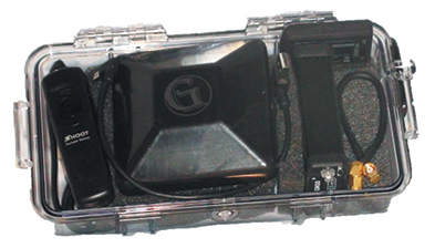
Components easily pack into a baseball-style case. Photo: Nicholas DiGruttolo
By Nicholas DiGruttolo
When asked to do a small survey job overseas, we were concerned about shipping bulky and expensive survey equipment. Shipping costs are not trivial. Add to that the real possibility that your survey equipment may be confiscated by the local authorities, as ours was in Djibouti, and the cost of shipping equipment becomes a substantial part of the overall job. There should be alternatives, especially if accuracy requirements are not stringent.
Faced with this problem for a second time, we considered a new receiver system that has many advantages over conventional survey-grade GNSS receivers: It is small, lightweight and low-cost without sacrificing performance, making it ideal for precision surveying in remote areas of the world and for traveling to the job site by commercial airline. All the components, including the tripods, rods and batteries, are constructed from commercial off-the-shelf (COTS) components. A complete base and rover kit fits in a baseball bag and weighs less than 10 kilograms. The kit is sized and approved as carry-on luggage.
The system is scalable from a simple single-frequency semi-mobile receiver for control networks and some semi-kinematic mapping applications, to a dual-frequency network RTK solution.
The system comes with free processing software that supports carrier-phase relative positioning in real time and post mission, as well as precise-point positioning (PPP) and CA-code differential correction. The software is designed with a simple user interface for easy selection of base and rover data or automatic data download of the closest Continuously Operating Reference Station (CORS) from the U.S. National Geodetic Survey database.
Complete survey set including GNSS receiver, antenna, battery and cables, fits in a small handheld plastic case. Photo: Nicholas DiGruttolo
The system fills a gap between survey applications, where centimeter-level precision is an absolute necessity, and mapping applications, where meter-level is tolerable. The product offers sub-foot precision in most cases and centimeter precision in ideal situations.
Our team recently performed topographic mapping of an oil refinery site in Saudi Arabia and surveyed a precise-elevation network in Sarasota, Fla., to research the effects of sea-level rise. The small size of the COTS components simplified transport to Saudi Arabia, eliminating additional airline baggage fees and easing import through customs. Researchers performing the sea-level study reduced field time by increasing the number of receivers needed to observe a robust vertical control network.
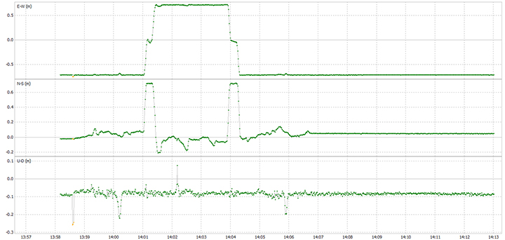
Oil Refinery. The oil refinery project entailed mounting a GNSS antenna on the roof of an off-road vehicle and driving multiple transects around the 18-kilometer perimeter of the site to record the elevation of the terrain. Kinematic data was recorded at 1 Hz using a GPS-only version of the single-frequency receiver. Baseline length to the local reference station varied from less than 1 kilometer to about 10 kilometers. The site was open desert with no overhead obstructions or sources of multipath other than the roof of the vehicle on which the antenna was mounted. Post-processing and comparison to simultaneously collected data from a high-precision survey-grade receiver revealed positional accuracy of about 5 centimeters horizontal and 10 centimeters vertical, when the system’s trajectory was compared to the truth trajectory provided by the survey-grade receiver. Figure 1 shows the difference between the two trajectories. The system’s antenna was 2 feet away from the survey-grade antenna along the driving direction of the vehicle; the trajectory was mostly in the north-south direction and hence the 0.6-m offset in the plot!
Figure 1. Antenna location difference in the sub-decimeter range between the survey-grade system and the compact low-cost system. Note: A 0.6-m offset is to be removed from the difference, as the two antennas were mounted 0.6 m apart in the vehicle driving direction.
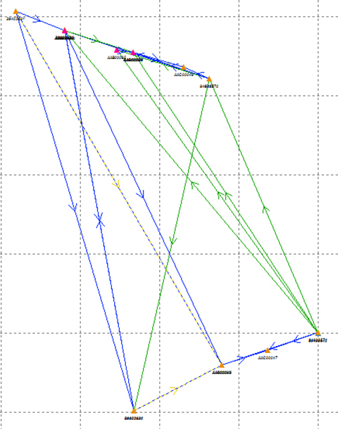
Sea Level. The sea-level-rise study required a high-accuracy vertical control network to cover a 2,500 hectare area. The purpose of the network is to determine the shortest term effects of sea-level rise with a rate of 1.8 millimeter/year in the affected area. Ten benchmarks were established throughout the area of interest, and a robust network of static observations was performed with a combination of two dual-frequency and two single-frequency receivers. The single-frequency receivers were GPS-only units where two standard 4-inch patch antennas were mounted on rods adjusted to a 0.9-meter height. The addition of two receivers provided greater redundancy and a stronger network solution in much less time than would have been possible with only one pair of survey-grade receivers. Figure 2 shows the addition of several loop ties to the network as a result of adding the two roving, lightweight receivers.
Figure 2. Sea-level rise monitoring network showing increased tie points and redundancy as a result of adding the extra lightweight precision receivers to the survey-grade receivers.
Nicholas DiGruttolo works as a field surveying manager for JBrown Professional Group Inc., Northrop Grumman Corporation, and has recently become vice president of surveying.
In the 2016 President’s Budget, submitted in February, the U.S. Air Force requested a budget of $122.2 billion. That exceeds the Office of Management and Budget’s recommendation by almost $10 billion. I applaud the Air Force action and think it may be too little, too late.
On the satellite or hardware side of the house, GPS III has problems centering on development and delivery issues with a subcontractor. In this case, however, the whole satellite program is not failing; just a component, albeit an important one: the Mission Data Unit or MDU.
For GPS III+, the Air Force plans for a two-phased competition process: a Production Readiness competition for up to three firm-fixed price contracts to mature competitors’ production designs for a competition in a full and open competition for up to 22 GPS III Production SVs [satellite vehicles] with an expected award in FY17/18.
This sounds great if you need an entirely new GPS III system, which consists of, at a minimum, a new payload, satellite, launcher and ground C2 system. OCX is only designed to work with current and planned GPS SVs, and it doesn’t even do that today. In fact, the government only needs an MDU, a critical part of the payload. Failure to produce the MDU on time has delayed GPS III by 18 months to date.
More troubling to me are the phrases from the government plan that essentially mean “We are going to pay competitors to mature their technology so they can compete against the current prime (LMCO), who is building the first 10 GPS III satellites.” The government is saying the competitors on their own cannot compete against LMCO so we, the government, are going to give them contracts and lots of money to help them get to a point where they can compete, and then we are going to have a recompetition.
This will to take at least three years and cost hundreds of millions of dollars, and LMCO may well win again in the end, but at least we will have conducted a competition. Does this make sense?
Will the U.S. Air Force initiate a competition to acquire an entirely new GPS III SV, or fix the problem with the current GPS III program, the MDU? It appears the Air Force is looking to pursue an entirely new GPS III system to include SVs.
A significant added cost to the GPS budget concerns the need for a new ground C2 system if the total new systems approach is taken. If preliminary elements of the GPS space segment are developed without cross-checking the impact to the GPS control segment, technical, operational, budgetary and schedule impacts will be significant.
The already troubled next-generation GPS ground control system, OCX, budget likely has not considered the integration costs of a newly developed, yet-to-be-procured GPS III+ SV. OCX today is geared for the GPS III already contracted for, and it is failing to meet that challenge in a spectacular and expensive way. It is possible, even probable, that OCX integration costs for yet another new model of GPS III family of satellites would increase the OCX budget significantly — unless one assumes that the Air Force acquires a perfectly matched new satellite that integrates seamlessly with OCX.What are the chances of that, and why would you spend hundreds of millions of scarce acquisition dollars to procure an exact and more expensive replica?
Budget constraints are tight and getting tighter, mandating the Air Force “do more with less” in every context. For GPS III SVs, this means developing an alternate MDU rather than buying a new block of GPS SVs.
The United States Civil GPS Service Interface Committee (CGSIC) has issued a notice about a problem some receivers are having implementing the correct time. The U.S. Coast Guard Navigation Center has received reports of synchronization issues since the implementation of a leap second on Jan. 21. Users experiencing this problem should contact the receiver manufacturer for a firmware or software update. Here is the text of the CGSIC notice:
All CGSIC: 2015 GPS Future Leap Second Implementation
The GPS 50 bit-per-second navigation message transmitted by each GPS satellite (specifically Page 18, subframe 4) includes the parameters needed to relate GPS time to UTC (Coordinated Universal Time).That relationship is maintained through leap second implementation transitions by IS-GPS-200 compliant user equipment.For leap second transition, user equipment must utilize the notice regarding a scheduled future delta time due to leap seconds (ÄtLSF), together with the week number (WNLSF) and the day number (DN), at the end of which the leap second becomes effective.
On or about Jan. 21, 2015, those GPS navigation messages began to include futurevleap second data which indicates an increase in the leap second to become effective at the end of June 2015.IS-GPS-200 revision H, dated 24 Sep 2013 paragraph 20.3.3.5.2.4 Coordinated Universal Time (UTC), documents the appropriate algorithm details to ensure correct utilization of the parameters above (including all potential truncated week number transitions and variations in time of processing relative to satellite upload timing near the future leap second effectivity).
The data upload for the June 30 leap second, initiated with SVN48/PRN07 at 18:33:56z on Jan. 21, was correctly executed. However, there are several receivers brands/models that seem to be mishandling this information and applying the leap second now. This is creating a negative one-second offset in faulty receivers. The U.S. Coast Guard Navigation Center has reports of these receivers causing synchronization issues with radios, computer systems, and data logging equipment.
Users experiencing issues with GPS receivers that began on Jan. 21 should contact the receiver manufacturer to determine if the latest firmware or software patch can correct the issue.
The third and fourth Galileo Full Operational Capability (FOC) satellites are a confirmed “fit” for their Arianespace Soyuz launch March 27, having made initial contact with the mission’s dual-payload dispenser in French Guiana, according to Arianespace.
The fit check was completed over a two-day period inside the Spaceport’s S1A payload preparation building. The two satellites were installed separately, with the Flight Model #3 (FM3) spacecraft integrated on — and subsequently removed from — the dispenser on Feb. 9. Flight Model #4 (FM4) underwent the same process the following day.
The payload dispenser for Galileo was developed by RUAG Space Sweden for Arianespace, and carries one satellite on each side. It will deploy the spacecraft during the Soyuz launch by firing a pyrotechnic separation system to release them in opposite directions at the orbital insertion point.
Final integration on the dispenser will be performed during upcoming processing at the spaceport, and will be followed by the completed unit’s installation on Soyuz.
The March 27 mission — designated Flight VS11 in Arianespace’s numbering system — will be the company’s fourth launch carrying spacecraft for the Galileo constellation.
Air Force Orders Two More GPS III Satellites
The United States Air Force plans to order two more GPS III satellites from contractor Lockheed Martin. Lockheed Martin is under contract to build eight GPS III satellites, with the first planned to be launched in 2016. The contract includes options for up to four more satellites.
However, the Air Force plans to open up construction of subsequent GPS satellites for competitive bidding with GPS III space vehicle 11. The satellites are part of the Air Force’s $167.3 billion budget request for fiscal 2016, up from $152.8 billion provided by Congress for fiscal 2015.
The Air Force also intends to buy only one GPS satellite — from Lockheed Martin or a different contractor — in 2017 rather than the three included in the current budget blueprint.
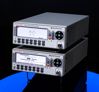
Spectracom GSG-Series GNSS Simulators have added capability to provide multiple RF outputs for advanced testing where multiple receivers or antennas are in use in a single system. Typical examples include controlled radiation pattern antennas (CRPA) or heading/attitude receivers and systems.
The intuitive StudioView software allows easy reconfiguration of test cases to change the conditions seen by one or all receivers and antennas under test — for example, adding a jamming signal to one antenna input on a CRPA receiver. Both over-the-air testing or cabled capabilities are available.
Because the simulator operates independently of PC control, the simulators can be precisely synchronized with a common clock and trigger pulse. There is no theoretical maximum to the number of RF outputs. This flexibility also allows testing multiple rovers reporting into a single control system, such as asset tracking or personnel location management systems.
This advanced feature is offered in both the L1 band GSG-5 series simulator for commercial applications as well as multi-band GSG-6 series simulator for professional applications.
TeleOrbit’s software-based GNSS multi-system performance simulation environment, GIPSIE, consists of a satellite constellation simulator and an intermediate frequency simulator. The digital signal simulator GIPSIE streams the software-generated signals or recorded live data exactly into the receiver’s baseband processing chain to support development, test, verification, validation, qualification and certification.
Features include simulation of multi-system, multi-frequency scenarios GPS L1/L2/L5 and Galileo E1/E5/E6; simulation of jamming signals on top of the GNSS signals; simulation of Galileo PRS-like signals as well as the unencrypted GPS P-Code signals; record and replay of recorded and software generated data. GLONASS and BeiDou constellations and signals and simulation of micro-electro-mechanical sensors (MEMS) are coming soon.
A leap second will be introduced this year at 23:59 on June 30. This phenomenon comes around periodically and is necessary for keeping Coordinated Universal Time (UTC) in line with the small vagaries of the Earth’s slowing rotation. Although it is an event that will pass unnoticed by the majority of people, it has implications for anyone involved in the development of GNSS-enabled devices. For some, it can be the cause of a major headache.
Part of the problem with the leap second is its irregularity. Occurring every two or three years, it means that receiver technology moves on in between — and because the Earth’s slowing rotation is not at a constant rate of change, it cannot be predicted when the next one will be announced. A rapidly developing market of GNSS products having to deal with random alterations to its time framework is not an ideal situation. Suitable preparations, clearly, should be employed.
The behavior of a new receiver when subjected to a leap second may prove critical in certain instances, and without robust characterization it can lead to inconsistent performance. It has already happened this year: on January 21, GPS signals started to include information which effectively announced this year’s leap second event, with the relevant data for future delta time, and week and day numbers. This caused issues with some receivers that weren’t expecting it: some units applied the additional second immediately. It would be interesting to see how these systems might have reacted during an actual leap second transition.
Receiver logic flow requires testing so that any GPS receiver can remain compliant with the IS-GPS-200 standard, and potential problems mustbe mitigated and controlled. The use of a GNSS simulator — which outputs a scenario containing the leap second event — allows for the receiver and any systems around it to be exercised over and over again, ironing out any anomalies, to ensure total reliability.
The recent issues with those non-compliant GPS engines highlights the advantage that simulation provides. The consistency it delivers enables a very thorough testing schedule, which will in turn lead to a straightforward application of the time change.
One school of thought holds that leap seconds should be abandoned, and that we should stick to atomic time from now on. Their removal would mean that by 2100, the Earth’s rotation would be some two to three minutes behind humanity’s precise, atomic-powered, 24-hour clock, and half an hour or so by 2700.
The World Radiocommunication Assembly, which has control over such matters, had been postponing a decision on whether to abolish the leap second for over a decade; another vote is due this year. It wouldn’t be any great wonder if this prevarication continues, so whilst it still exists, it is best to concentrate on what this June’s extra second might have in store for anyone currently developing a GNSS product. Armed with a simulator, the unpredictability of leap second scheduling should no longer be a major concern. Should this year’s vote be again inconclusive, those who have taken the positive step of acquiring a GNSS simulator will be in good shape to deal with the next time the clocks show 23:59:60.
Mark Sampson is LabSat product manager for RaceLogic.
SPAR International is a platform-neutral conference and exhibition focused on end-to-end business and technology for 3D measurement and imaging for industrial facilities; engineering, architecture and construction; and civil infrastructure. The exhibition will showcase solutions from leading 3D hardware manufacturers, software suppliers and service providers.
The conference and trade show will be held March 30-April 2 in Houston, Texas.
Watch a video about the conference:
At SPAR International, current and emerging 3D technology and lifecycle asset-management solutions will be highlighted. More than 90 experts in 3D data, point-cloud processing, and data delivery will explain how to improve processes, mitigate risk, get the necessary output, and save time and money.
This year SPAR features a dedicated UAV pavilion, where attendees can learn about the market and discuss solutions with major manufacturers. It also features a hologram room — a taste of the future that puts you inside a 3D scan.
On the exhibit floor, developers and manufacturers will showcase the latest solutions developed to solve pressing and complex problems in a range of industries. 3D scanners, low-cost handheld devices, mobile mapping solutions, advanced data processing workflows, and more will be featured.
Learning levels for 2015 include:
Business Consideration: Critical topics for asset owners and business leads.
3D Technologies and Applications: In-depth content for 3D pros.
Introduction to 3D Tools: Basics for beginners and those new to 3D.
Other topics covered include:
Building Information Modeling (BIM)
3D for asset and facilities management
3D data capture for as-built conditions
Point-cloud processing
Managing and sharing large data sets
3D/intelligent modeling
Augmented reality and visualization tools
UAVs/UAS
Numerous networking events provide opportunities to gain valuable information from other precision-measurement and imaging professionals across disciplinary lines. Attendees can discuss best practices, share project experience, and benefit from the experiences of their peers.
Editor’s note: GPS World Innovation editor Richard Langley has co-authored a study, described below, exploring how irregularities in Earth’s upper atmosphere can distort GPS signals, an important step toward mitigation.
The Aurora Borealis viewed by the crew of Expedition 30 on board the International Space Station. The sequence of shots was taken on February 7, 2012 from 09:54:04 to 10:03:59 GMT, on a pass from the North Pacific Ocean, west of Canada, to southwestern Illinois. Image Credit: NASA/JSC
News from the Jet Propulsion Laboratory
When you don’t know how to get to an unfamiliar place, you probably rely on a smartphone or other device with a GPS module for guidance. You may not realize that, especially at high latitudes on our planet, signals traveling between GPS satellites and your device can get distorted in Earth’s upper atmosphere.
Researchers at NASA’s Jet Propulsion Laboratory (JPL), Pasadena, Calif., in collaboration with the University of New Brunswick in Canada, are studying irregularities in the ionosphere, a part of the atmosphere centered about 217 miles (350 kilometers) above the ground that defines the boundary between Earth and space. The ionosphere is a shell of charged particles (electrons and ions), called plasma, that is produced by solar radiation and energetic particle impact.
The new study, published in the journal Geophysical Research Letters, compares turbulence in the auroral region to that at higher latitudes, and gains insights that could have implications for the mitigation of disturbances in the ionosphere. Auroras are spectacular multicolored lights in the sky that mainly occur when energetic particles driven from the magnetosphere, the protective magnetic bubble that surrounds Earth, crash into the ionosphere below it. The auroral zones are narrow oval-shaped bands over high latitudes outside the polar caps, which are regions around Earth’s magnetic poles. This study focused on the atmosphere above the Northern Hemisphere.
“We want to explore the near-Earth plasma and find out how big plasma irregularities need to be to interfere with navigation signals broadcast by GPS,” said Esayas Shume. Shume is a researcher at JPL and the California Institute of Technology in Pasadena, and lead author of the study.
If you think of the ionosphere as a fluid, the irregularities comprise regions of lower density (bubbles) in the neighborhood of high-density ionization areas, creating the effect of clumps of more and less intense ionization. This “froth” can interfere with radio signals including those from GPS and aircraft, particularly at high latitudes.
The size of the irregularities in the plasma gives researchers clues about their cause, which help predict when and where they will occur. More turbulence means a bigger disturbance to radio signals.
“One of the key findings is that there are different kinds of irregularities in the auroral zone compared to the polar cap,” said Anthony Mannucci, supervisor of the ionospheric and atmospheric remote sensing group at JPL. “We found that the effects on radio signals will be different in these two locations.”
The researchers found that abnormalities above the Arctic polar cap are of a smaller scale — about 0.62 to 5 miles (1 to 8 kilometers) — than in the auroral region, where they are 0.62 to 25 miles (1 to 40 kilometers) in diameter.
Why the difference? As Shume explains, the polar cap is connected to solar wind particles and electric fields in interplanetary space. On the other hand, the region of auroras is connected to the energetic particles in Earth’s magnetosphere, in which magnetic field lines close around Earth. These are crucial details that explain the different dynamics of the two regions.
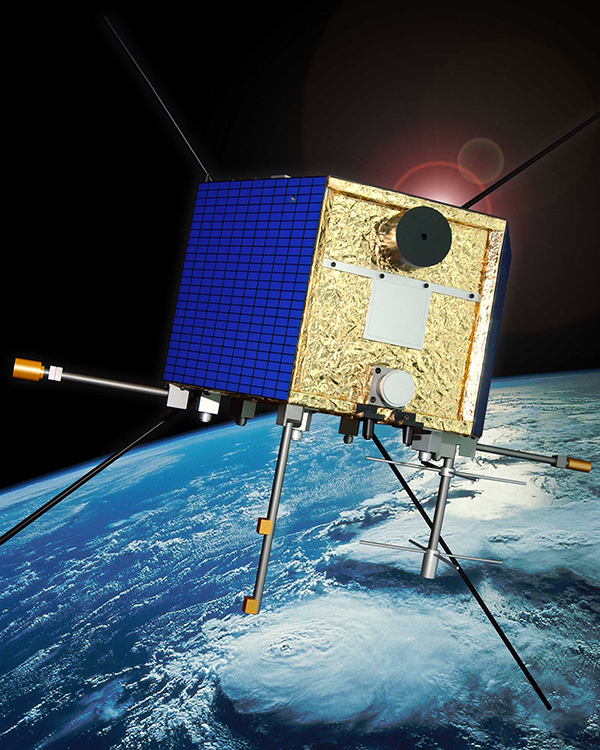
CAScade, Smallsat and IOnospheric Polar Explorer (CASSIOPE) is a made-in-Canada small satellite from the Canadian Space Agency. It is comprised of three working elements that use the first multi-purpose small satellite platform from the Canadian Small Satellite Bus Program. Image Credit: Canadian Space Agency
To look at irregularities in the ionosphere, researchers used data from the Canadian Space Agency satellite Cascade Smallsat and Ionospheric Polar Explorer (CASSIOPE), which launched in September 2013. The satellite covers the entire region of high latitudes, making it a useful tool for exploring the ionosphere.
The data come from one of the instruments on CASSIOPE that looks at GPS signals as they skim the ionosphere. The instrument was conceived by researchers at the University of New Brunswick.
“It’s the first time this kind of imaging has been done from space,” said Attila Komjathy, JPL principal investigator and co-author of the study. “No one has observed these dimensional scales of the ionosphere before.”
The research has numerous applications. For instance, aircraft flying over the North Pole rely on solid communications with the ground; if they lose these signals, they may be required to change their flight paths, Mannucci said. Radio telescopes may also experience distortion from the ionosphere; understanding the effects could lead to more accurate measurements for astronomy.
“It causes a lot of economic impact when these irregularities flare up and get bigger,” he said.
NASA’s Deep Space Network, which tracks and communicates with spacecraft, is affected by the ionosphere. Komjathy and colleagues also work on mitigating and correcting for these distortions for the DSN. They can use GPS to measure the delay in signals caused by the ionosphere and then relay that information to spacecraft navigators who are using the DSN’s tracking data.
“By understanding the magnitude of the interference, spacecraft navigators can subtract the distortion from the ionosphere to get more accurate spacecraft locations,” Mannucci said.
Other authors on the study were Richard B. Langley of the Geodetic Research Laboratory, University of New Brunswick, Fredericton, New Brunswick, Canada; and Olga Verkhoglyadova and Mark D. Butala of JPL. Funding for the research came from NASA’s Science Mission Directorate in Washington. JPL, a division of the California Institute of Technology in Pasadena, manages the Deep Space Network for NASA.