Everbridge has launched a Summer Release of its Unified Critical Communication Suite with new mobile, GIS, and expanded alerting enhancements that enable Everbridge customers to deliver unified critical communications and situational intelligence within the context of their recipient’s needs, roles, and locations.
As enterprise mobility, BYOD, and other unified communications drivers continue to converge in an increasingly global, yet unpredictable world, organizations deploy Everbridge’s Unified Critical Communication Suite to respond and collaborate during both emergency and operational incidents, the company said.
The latest release expands upon the recently launched spring release, offering new features designed to unify multi-modal, critical communications for diverse industries, including corporations, state and local government, healthcare, financial services, and higher education. The summer release includes new updates to Everbridge’s recently unveiled IT Alerting solution — specifically designed for IT Operations teams to improve communications and collaboration during incidents, resolving issues faster, and maximizing IT system uptime.
Additional upgrades to the summer release include:
PrecisionGIS: Everbridge’s rich GIS functionality now includes three new map-based targeting capabilities:
Geofencing: This new feature enables users to draw simple or multiple complex polygons to define boundaries and control the behavior of addresses located inside or outside the “fence.”
Custom Base Maps: Everbridge supports commercial mapping applications, including Google, Bing and ESRI, and now enables organizations to overcome existing gaps with commercial maps by customizing the base map used within the Everbridge suite. The base maps can include the geographical or infrastructure information users need to make more informed decisions when preparing and targeting a message.
Point-Address Geo-Coding: Users can now manage and provision all addresses down to the parcel level to ensure the data is accurate and precise enough for critical communications. This enables an advanced level of custom and granular geocoding capabilities beyond what is available via commercial geo-coding applications.
Rich Text Formatting: The Everbridge suite provides enhanced rich text formatting support for email, enabling users to send the right message to the right contact path. Users can now deliver full-featured, unique messages, including entire web pages without modification, optimized for Phone, SMS, Email, and Push Notification contact paths.
Mobile Enhancements: New mobile device registration simplifies user access and improves Mobile Member opt-in. New enhancements also include “silent mode” override for Android mobile devices to ensure that critical messages get delivered at all times.
On-the-Go Alerting: This new partner functionality enables users to create and transmit customized alert messages directly from an iPad application. Users can draw affected areas directly on a map, while sending and receiving notifications through IPAWS communications channels.
On-Call Scheduling: Everbridge now provides robust on-call scheduling to automate outreach to on-call teams with rotating coverage or complex shift changes. Seamlessly integrated with Everbridge notifications, on-call scheduling eliminates the need for manual call lists and handwritten calendars.
“The new enhancements to our summer release reflect our continuing commitment to product investment and innovation,” said Imad Mouline, CTO of Everbridge. “Our customers are confronted daily with new challenges and opportunities related to mobility, business continuity, emergency notification, secure messaging, and more. We will continue to evolve our suite to meet these challenges—unifying critical communications across modalities and devices on a global scale.”
Trimble has introduced the latest version of its smart water infrastructure mapping and work management software — Trimble Connect version 1.8. The latest release of the cloud-based, geographic information system (GIS)-centric software includes a suite of applications that allow water, wastewater and stormwater utilities to visualize and efficiently manage their network maintenance and data collection activities.
Trimble Connect software leverages Trimble’s GNSS rugged mobile devices and Esri’s GIS technologies to accurately map, locate and assess the condition of critical infrastructure assets, allowing utilities to keep their field infrastructure data up-to-date and accurate. Offered as a software-as-a-service (SaaS) subscription, the solution allows users to monitor asset operating conditions, manage leak repairs, reduce non-revenue water, deploy and inspect smart meters, lower potential threats to safety and health due to contamination and adhere to regulators’ reporting guidelines and requirements. Trimble Connect version 1.8 can be configured and deployed quickly on a variety of Trimble and non-Trimble mobile devices, laptops, tablets and smartphones, including Apple iPads, iPhones, Android, Windows and Windows Mobile devices to automate field workflows and eliminate paper-based maps.
Trimble Connect utilizes the latest Esri ArcGIS 10.2.2 for Server, Mobile and ArcGIS Online basemap services. The software is designed to automate a variety of specific water and wastewater industry workflows through individual “apps” offered within the product and as part of a subscription. The new version provides standard core apps including Map Book, Manhole Inspector, Leak Repair, Hydrant Inspector, Valve Inspector, Meter Changeout, Incident Repair, Water Mapper, Wastewater Mapper and Stormwater Mapper. In addition, an optional partner app developed for American Flow Control (AFC) hydrant and valve data collection, “AFC Mapper,” can be purchased from AFC and their distributors for use with Trimble rugged handhelds.
In addition to the standard core apps, Trimble Connect version 1.8 includes:
Full offline mobile support including GIS data for Android, iOS, Windows Mobile and Windows 7/8 platforms
Esri ArcGIS Online (AGOL) support to create and share Web Maps using data collected in Trimble Connect
Work management support for single and multi-asset work orders on all supported platforms
Enhanced workflows for asset inspection and condition assessment
Embedded business rules to define failed inspections or ones that need review
Enhanced workflows for asset mapping and data collection
Support for the Trimble Geo 7 series rugged mapping handheld and integrated Laser Rangefinder
Trimble has announced three new asset inspection software solutions for heavy civil contractors—Trimble Inspector, Trimble Inspector Pro and Trimble Asset Manager.
Trimble Inspector is a free mobile app that allows equipment managers to easily inspect assets in real-time using their smartphone or tablet.
Trimble Inspector Pro, the premium, subscription version of Trimble Inspector, is used to wirelessly aggregate and share asset condition across multiple sites using Trimble Asset Manager office software.
Trimble Asset Manager software gives contractors the ability to store the inspection data of all assets in a centralized, Web-based database for accurate reporting and documentation.
“Contractors can achieve significant cost savings by proactively scheduling asset maintenance with Trimble’s new inspection solutions,” said Alan Sharp, business area director for Trimble Heavy Civil Construction. “Trimble takes the guesswork out of asset maintenance and puts the control back in the hands of the equipment manager.”
Trimble Inspector, a free mobile app, runs on both Android and iOS smartphones or tablets for daily, weekly and monthly visual inspections using a library of equipment, machine and vehicle types, makes and models, and inspection checklists. Reports containing current visual health status, hours, odometer reading and general condition can be promptly emailed to equipment and maintenance managers. The reports, along with photos, can then be retained for legal documentation of health and safety standards compliance, and for audit purposes. In addition, Trimble Inspector assists with scheduling maintenance to reduce equipment downtime and unplanned stoppages. The app is also ideal for trade-in or auction house inspections of used equipment.
Trimble Inspector Pro has all the functionality of Trimble Inspector, with the added benefits of customized inspection reports to meet health and safety requirements, and comprehensive maintenance reports for service crews. Equipment managers can record equipment service issues and notify site management staff of equipment status on multiple sites within seconds of the completed inspections. Trimble Inspector Pro requires a subscription to Trimble Asset Manager office software to access the additional functionality.
Trimble Asset Manager is a software as a service (SaaS) application used in the office to integrate, store and report asset condition data collected in the field by Trimble Inspector Pro. Asset information is kept in a secure, centralized online database accessible by authorized users in the company. Users can create asset records, document inspections and customize reports so managers get the data they need quickly and easily.
Trimble Inspector and Trimble Inspector Pro are available now worldwide from the Google Play Store or the Apple App Store. Trimble Asset Manager is available now globally through Trimble’s SITECH Technology Dealer Channel.
“Aeroptic is a commercially available mapping system that supports every mission in which the National Guard engages, ranging from incident assessment and disaster response in Domestic Operations (DOMOPS) to reconnaissance and situational awareness on the OCONUS battlefield,” said Kevin Gunde, executive vice president, Surveillance and Exploration Systems. “Aeroptic can be deployed on a variety of fixed- and rotor-wing platforms, including the National Guard UH-60 Blackhawk.”
KEYW developed the Aeroptic solution with image quality, positional accuracy and ease of use in mind. The system integrates a full-color electro-optical (EO) camera, GPS/IMU, and user-friendly geo-processing software based on non-proprietary open standards. The system is compact, light-weight and ruggedized for deployment in harsh environments.
The rapid-refresh EO camera captures imagery of extraordinary quality by employing advanced noise reduction, image sharpening algorithms and high-end lenses with innovative configurations, the company said. The interchangeable lenses offer multiple focal length options that enable the Aeroptic camera to acquire high-resolution visible-band imagery with sub-meter geo-positional accuracy from varying flight altitudes without surveyed ground control points.
Aeroptic offers the option of processing imagery in the air or on the ground, producing unclassified, wide-area ortho-mosaic maps in near real time. Generated imagery products are ready for immediate ingest into standard commercial viewing tools and GIS packages.
“No expertise in GIS or cartography is needed to make full use of the Aeroptic system,” said Kevin Gunde, executive vice president, Surveillance and Exploration Systems. “With just eight hours of training, the typical user can produce content-rich image maps ready for distribution within minutes after acquisition.”
KEYW will be discussing the Aeroptic Mapping System and its many mission applications in booth #512 at the NGAUS General Conference & Exhibition being held August 22-25, 2014, in Chicago’s McCormick Place.
The European GNSS Agency (GSA) has launched a call for proposals to foster further EGNOS adoption in the European civil aviation sector. The grant aims to support projects that enable users to equip and use their aircraft or rotorcraft fleet with GPS/SBAS-enabled avionics and allow Air Navigation Service Providers and aerodromes/heliports to implement EGNOS-based operations in Europe.
The purpose of the call is to co-fund projects capable of fostering EGNOS operational implementation for regional, business and general aviation and rotorcraft. In addition, commercial operators and original equipment manufacturers (OEMs) interested in benefiting from EGNOS may also apply.
Specifically, the call aims to:
Foster the design, development and operational implementation of EGNOS-based operations, including approach procedures at different European aerodromes and EGNOS based routes.
Develop and install GPS/EGNOS enabled avionics and granting of airworthiness certification for RNP APCH procedures down to LPV minima, including the development of Supplemental Type Certificates (STC) or Service Bulletins (SB).
Approve Air Operator Certificates for LPV operations of aircraft already equipped with SBAS capabilities.
Develop enablers to accelerate EGNOS adoption and preparation for its future capabilities, such as LPV 200.
The deadline for submitting applications is 16:00 CET, October 31.
Applications will be assessed in terms of relevance of the proposal and credibility of the proposed approach, economic and societal impact, and coherence and effectiveness of the work plan.
The total budget of the call is EUR 6,000,000 and maximum EU financing of eligible direct costs is 60 percent. In addition, a flat-rate amount of 7% of the total eligible direct costs of the action is eligible under indirect costs.
Awarding of the grants will happen in December 2014, with each grant agreement having an estimated duration of two years.
The Japan News is reporting that the Japanese Committee on the National Space Policy has compiled a draft proposal that includes increasing the number of quasi-zenith satellites (QZSS), Japan’s satellite navigation system, from the current single satellite to a total of four.
Currently, Japan is operating only one quasi-zenith satellite, named Michibiki.
The increase would be made to strengthen Japan’s overall surveillance systems, in light of developments such as China’s maritime expansion. “China’s high-pressure maritime advances have become a menace to the security of countries in Asia. Continued vigilance is also required against North Korea’s missile launches and nuclear weapons development program,” according an editorial published by The Japan News.
The additional QZSS satellites would presumably supplement Japan’s surveillance satellites with positioning information. Japan currently has four information-gathering satellites, which lack the flexibility to boost the accuracy of ground surveillance activities and swiftly grasp movements of objects such as vessels at sea.
“For surveillance activities, acquisition of high-precision positioning information using space technology is also important. Only the global positioning system (GPS) run by the United States is currently reliable for this purpose,” the editorial said.
A four-satellite QZSS system will allow positioning surveillance of all regions around the clock. Based on the proposal, the government is expected to revise the Basic Plan on Space Policy within the year.
The proposal also stipulates that the country should aim to operate seven quasi-zenith satellites as early as possible, which would allow stable management of the system, according to The Japan News.
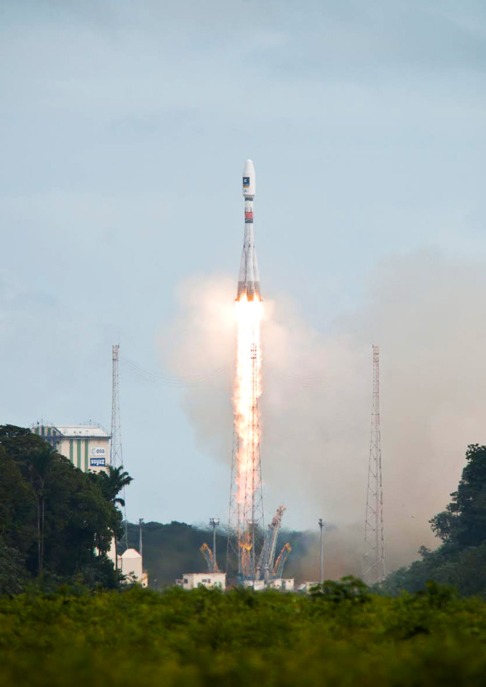
Soyuz Flight VS09, carrying Europe’s fifth and sixth Galileo satellites, lifts off from Europe’s Spaceport in Kourou, French Guiana.
Soyuz Flight VS09, carrying Europe’s fifth and sixth Galileo satellites, lifted off from Europe’s Spaceport in Kourou, French Guiana, today (August 22, 12:27:11 UTC/14:27:11 CEST.)
All the stages of the Soyuz vehicle performed as planned, with the Fregat upper stage releasing the satellites into their target orbit close to 23,500 km altitude, 3 hours 47 minutes after liftoff.
These new satellites joined four Galileo satellites already in orbit, launched in October 2011 and October 2012 respectively. This first quartet were In-Orbit Validation (IOV) satellites, serving to demonstrate the Galileo system would function as planned.
Satellites 5 and 6, the first Full Operational Capability (FOC) satellites, are significant as the first of the rest of the Galileo constellation. This launch marks the start of a new phase in the European satellite navigation program where the full constellation will be deployed with short intervals between launches. A steady stream of launches will follow to build the complete Galileo constellation.
Watch a video of the launch here:
On completion of the initial checks, run jointly by the European Space Agency (ESA) and the French space agency CNES, the two satellites will be handed over to the Galileo Control Centre in Oberpfaffenhofen, Germany, and the Galileo in-orbit testing facility in Redu, Belgium, for testing before they are commissioned for operational service in the autumn.
The deployment of the constellation will now move more quickly, with six to eight satellites launched per year using a series of Soyuz and Ariane launches from the CSG, along with finalization of the remaining elements of the ground network.
The final constellation will consist of 24 satellites expected to be ready in 2017 and complemented by six in-orbit spares.
This deployment phase of the Galileo program is being managed and funded by the European Commission, with ESA acting as design and procurement agent on behalf of the Commission.
On the tail of the Esri International User Conference (UC) and the first-ever live event webinar we’ve ever conducted, I’d like to revisit a subject I’ve pounded hard for the past couple of years. It’s a subject that still, after my 25 years in the geospatial industry, is still the most common problem that geospatial users ask me about.
First, however, the live event webinar at the Esri UC. What a blast it was to broadcast live from San Diego with people walking by and the buzz of 14,000+ conference attendees in the air! I’ll definitely be looking for more opportunities to broadcast live from events like this. The webinar was great. It touched primarily on high-precision GNSS on mobile devices. If you weren’t able to attend and would like to listen to it, register here and you’ll be sent a web link. Then, just last week I conducted a follow-up webinar that dug further into the details of how to use RTK (real-time 1-2 cm accuracy) on almost any mobile device. If you missed it and would like to listen to it, register here and you’ll be sent a web link.
So, what is the #1 question I was asked 20 years ago and is still the #1 question I’m asked about today?
“Why doesn’t my GPS data line up?”
Part of the reason that the question has been a consistent perennial favorite is that low- to medium-cost GPS (now more commonly referred to as GNSS) receivers have become more accurate, so our expectations for better accuracy have increased. It used to be that 2-5 meters (after post-process differential correction) was about what you could expect from a $10,000 GPS receiver. Today, you can buy a real-time, submeter receiver for under $2,000 and an RTK receiver capable of 1-2 cm accuracy for two to three times that.
So, “why doesn’t my GPS data line up?”
I wrote two articles that attempted to summarize the problem. The two-part series was entitled “Nightmare on GIS Street.”
Horizontal datums, and changing horizontal datums, are the root of the problem. Lack of user knowledge and GIS software vendors’ improper implementation of horizontal datum transformations exacerbate the problem.
There are a few common horizontal datums used, at least in the U.S.. Outside of the U.S., there a myriad of datums with associated transformation algorithms. A few common ones are:
ITRF08 – International Terrestrial Reference Frame of 2008. ITRF08 is world-wide datum with no epoch (time stamp) associated with it.
WGS-84 (G1674) – World Geodetic System of 1984. WGS-84 has changed substantially over the years. G1674 is the latest revision (actually, I think G1762 is out but I’ll leave that for now). At epoch 2005.0 (January 1, 2005), WGS-84 (G1674) and ITRF08 are within a centimeter of each other.
NAD83/2011 – North American Datum of 1983. As with WGS-84 and ITRF, NAD83 has undergone significant changes over time. The current version is NAD83/2011 with an epoch date of 2010.0 (January 1, 2010).
Now, it would be great if all of our geospatial data was referenced to the same datum. In that case, all of our geospatial data would line up perfectly. But, it’s not that easy. In fact, not only is data published in all three of the above datums (and more), but also a lot of legacy geospatial data is published in earlier versions of the datums above, which can significantly differ from the current revision of the same datum.
For example, if you received geospatial data that is reported to be referenced to NAD83? What does that mean? Is it the original version of NAD83 or is it the latest revision of NAD83 (2011) or somewhere in between?
Let’s take a practical and very common example.
Assume you’ve got a high-precision handheld GNSS receiver. Unless you’re connected to a RTK network or post-processing, you’re likely using WAAS as a source of GPS corrections, which is a very common setup.
Let’s say that your GIS database is referenced to NAD83/2011, another very common setup.
WAAS is referenced to ITRF08 current year epoch.
ITRF08 differs from NAD83/2011 from 2 to 4.5 feet in the U.S. depending on the geographic region you work in. So, if you don’t adjust your incoming data to match NAD83/2011, the data you add to your GIS database will be offset by 2 to 4.5 feet. Following is a graphic from Michael Dennis of the National Geodetic Survey that illustrates the difference between NAD83/2011 and WGS-84/G1672.
Source: National Geodetic Survey
What’s really important to note about the slide above is the epoch date. I write about the time variable of datums in Part2 Nightmare on GIS Street: Accuracy, Datums, and Geospatial Data. The bottom line is that the ground we walk on moves. It’s only very slightly, unless there’s an event like an earthquake, but it’s constantly moving, and generally in the same direction and rate. In the midwestern U.S., for example, the ground may only be moving a few millimeters per year. In some places in California, the ground moves 4 cm per year. If you’re using RTK to achieve 1-2 cm precision, 4 cm is a big number and can’t be ignored. If you located a point five years ago with RTK to the 1-2 cm level and revisited it today, the difference would be 20 cm, well over a half foot.
What methods are available to adjust for the difference between the two datums?
There are at least three ways I can think of. Of course, the easiest one is if the data-collection software you use is smart enough to deal with this. Unfortunately, this is not likely. Surprisingly, even mainstream GIS data collection software sold today doesn’t address this problem.
Some data collection software (ArcPad, SurvCE, FieldCE) have the functionality to define the GPS datum and apply a datum transformation in real time (in the field) so it’s transformed to NAD83/2011 before it’s stored in the GIS database. Note, however, that even fewer are able to deal with crustal movement. For example, take a coordinate time-stamped 2008 and “move” it to 2014.
Apply the datum transformation after the data is collected.
If your GIS software doesn’t have the correct datum transformation functionality built in, use a tool such as HTDP (Horizontal Time Dependent Positioning) to determine a precise offset distance and direction in and apply the offset to all of the data collected in that geographic region. Since WAAS precision is 50 cm at best, this type of offset correction is perfectly suitable.
As I mentioned in no. 1 above, several software packages can transform between datums, but very few can take into account the time component of datum transformations. In other words, they don’t take into account the fact that the ground we stand on is moving.
Some people are beginning to take note that addressing the time component of datum transformations is just a matter of time, which it is. For example, Geomobile Innovations just introduced a plug-in for ArcPad that adds extensive datum transformation functionality to ArcPad, including accounting for the ground movement. It turns ArcPad into a true high-precision data-collection tool.
More good news is that the big dog is starting to wake up. At the Esri UC last month, I heard from a reliable source that Esri has made dealing with this issue an active project, and is working on the logic and user interface to implement a time-dependent datum transformation model (commonly known as a 14-parameter transformation). As someone who used to design GIS data-collection logic and user interfaces, I can appreciate the challenge of implementing this model. What happens when a road/pipeline/transmission line crosses from one tectonic plate to another when the two plates are not moving the same direction and velocity? How does one make accounting for that easy to use yet technically correct?
UPDATE: The next launch attempt for Soyuz VS09 with Europe’s fifth and sixth Galileo satellites is Friday, August 22, at 12:27 GMT, 14:27 CEST. Arianespace had decided to postpone the launch of Soyuz flight VS09 carrying Europe’s fifth and sixth Galileo satellites, because of unfavorable weather conditions over the Guiana Space Centre.
During the European Space Agency (ESA) audio press conference held Wednesday morning in advance of Thursday’s launch of two Galileo satellites, there was extended discussion on the problem with the fourth in-orbit validation or IOV satellite (FM4 or GSAT0104 with PRN code E20). The satellite suffered a power anomaly on May 27 as previously reported by GPS World.
The root cause of the problem has still not been identified despite looking at more than 40 possible failure scenarios so far. ESA has conducted extensive analyses of telemetry from the satellite as well as reviews of pre-launch tests. It has been determined, however, that the E5 and E6 frequencies have had a permanent loss of power. E1 appears to be OK and can be switched back into normal operation at any time. Currently, the satellite is transmitting on E1 but using a non-standard test code.
It was also revealed that FM2, the second IOV satellite, suffered a power drop of 2 dB about a year ago, and FM1, the first IOV satellite, has also seen a power drop. In the case of FM1, the problem is in the primary solid-state power amplifier, and there is a plan to switch shortly to the back-up unit. However, there doesn’t appear to be a common-mode of failure relating the power losses on the various satellites.
While the FM4 anomaly investigations are ongoing, the power on all of the IOV satellites has been backed off 1.5 dB.
Concerning the two full operational capability or FOC satellites to be launched tomorrow, ESA is not yet revealing into which orbit plane and slots the satellites will be placed. Nor are they saying yet which pseudorandom noise codes will be used by the satellites. Once the satellites are launched into their preliminary orbits, it will take about two weeks for them to drift to their assigned locations. At that time, we should be able to deduce their locations using, for example, United States Strategic Command (USSTRATCOM) tracking data. And once they begin transmitting standard PRN codes, all-in-view receivers, such as those participating in the International GNSS Service Multi-GNSS Experiment, will be able to identify their codes.
The satellites will undergo testing for 73 days, after which they will be declared operational. ESA intends to use the passive hydrogen maser clocks on the satellites as the primary clocks, with the rubidium clocks used as back-ups.
Omnitracs, LLC, a provider of fleet management solutions to transportation and logistics companies, is making available Omnitracs Tracking powered by Roadnet, a mobile workforce tracking application for smart devices. Omnitracs Tracking offers basic capabilities to help companies track the locations of their mobile workers throughout the day and get additional performance data to help make them safer and more productive, the company said.
“Every transportation company with a mobile workforce wants to know the location and key behaviors of their drivers,” said Dan Speicher, chief technology officer at Omnitracs. “Omnitracs Tracking powered by Roadnet enables companies that have not adopted a fully featured mobile fleet management solution to utilize their existing smart devices in order to track locations of mobile workers, improving safety, productivity and customer satisfaction.”
Benefits of Omnitracs Tracking include:
Location Tracking. By leveraging existing smart device GPS positioning technology, location tracking pinpoints drivers’ locations in real-time using satellite and street maps. Fleet managers access this information through a web-based application, enabling them to provide customers with timely updates on the status of their delivery or service call.
Speed Tracking. The application monitors drivers’ speed throughout the day, allowing fleet managers to take prompt action to help preempt potential safety issues.
Exception Reporting. Users can predefine thresholds for maximum speed allowed, GPS gap, over road speed and stationary position time limits. Exception reporting helps to quickly identify driver behaviors that may lead to unsafe driving and reduced productivity.
“Omnitracs is committed to leveraging the expertise and capabilities of our business units to continuously bring value to our customers. Our newest basic tracking application will give companies the tools they need to better manage their mobile workforce and take fast, appropriate action to improve safety and productivity,” added Speicher.
Omnitracs Tracking is available exclusively through Roadnet and Omnitracs’ resellers. For more information about the application, visit.
The new Renishaw Quarryman Pro 3D laser scanner system uses innovative technology to help optimize blasting and increase the profitability of quarrying operations, according to Renishaw. The system, which also helps to improve safety, was launched at the Hillhead 2014 Tradeshow, held June 24-26 in Buxton, UK.
Quarryman has offered on-site systems for quarries for more than 20 years, improving safety and allowing quarry managers to modify processes simply and swiftly, the company said. The new Renishaw Quarryman Pro is optimized for speed of operation in tough environments, with swift set-up, programming, scanning and data processing, and offers significant benefits over previous models.
New viewing and editing software is quicker to operate, easier to integrate with other mapping software, and includes filtering and data processing functionalities. The sun-readable screen is larger than on previous models, for better visibility, and is now in full color. Data is saved to a USB, rather than a flashcard, for ease of data transfer and larger file capacity.
A GPS mount is built into the handle for quick positioning and easy mapping of point-cloud data to other quarry maps using coordinates, and auto date and time stamping help operators find files, without needing to enter details.
A new Li-ion battery is lighter, provides a greater scan time, and issues a warning when power is low. It also shuts down automatically if not recharged, retaining data for operators to retrieve later. The system’s operating temperature range and processing power have also been increased.
“Customers using the new Quarryman Pro alongside Renishaw’s Boretrak system will see a significant competitive advantage,” said Martin Carr, Business Manager, Mining Systems. “Quite simply, they will access accurate data more quickly, in a wider range of conditions, and be more easily able to export data to other mining software packages. In 20 years of working with quarries, including some of the world’s largest and most competitive global quarrying companies, Quarryman Pro is the best product we have developed, and marks the beginning of a new era for laser scanning systems for the mining and quarrying sectors.”
“The new Quarryman Pro is the first system developed, engineered and manufactured by Renishaw, and customers now have one of the world’s leading engineering technology companies behind the support and service of every unit sold,” said Will Lee, Director and General Manager of Renishaw’s Spatial Measurement Division.