The troubled Galileo E20 satellite restarted E1 signal transmission Wednesday evening, August 6.
Galileo E20, also known as GSAT0104, the fourth in-orbit validation (IOV) satellite, has been set “unavailable until further notice” according to the European GNSS Service Centre because of a sudden, unexpected loss of power on May 27.
Based on a selected set of IGS MGEX stations and all CONGO stations, the first signals were tracked at AREG, AUT0, LLAG, and UNB3 at 23:13:00. No E5 signals and no navigation messages are currently transmitted. However, some JAVAD GNSS receivers report from time to time false E5a locks with zero or extremely small C/N0.
As you may know from previous columns, I’m a big proponent of oblique imagery and 3D models for non-GIS users such as first responders or the general public. The primary reason is that most non-geospatially-trained people have a hard time getting oriented when viewing only abstract maps or ortho imagery. Oblique views are the way we navigate our natural 3D world, so anything less is not ideal.
Many products and services provide oblique imagery and 3D models. Pictometry, Bing (Pictometry imagery), and Google provide oblique views. Numerous companies build 3D models such as AEgis Technologies, Esri with City Engine, Cyber City 3D, and PLW Modelworks, which builds probably the most photorealistic and photo-accurate models.
Each company builds its 3D models or views with slightly different technology and methods. This year at GEOINT, Raytheon caught my attention with a 3D-model creation process that uses only 2D imagery, even satellite imagery of locations that are not accessible by ground or air. The system, called Intersect Dimension, doesn’t use LiDAR, but leverages passive 2D and other remote-sensing imagery sources to automatically create high-accuracy 3D models very quickly and for a fraction of the expense of current multi-dimensional modeling solutions. Dimension uses a Raytheon-patented technology to automate optimal image selection and geometric registration to build models with high positional accuracy and optimal resolution.
Unlike LiDAR-generated 3D data, Dimension’s passive 3D point clouds offer several advantages, including
global coverage in airborne-denied geographies or in areas with outdated flyover information
extensive coverage from multiple data sources
compatibility with a broader selection of data sources, including archived (historic) images
faster turn-around times with fully-automated renderings requiring no human intervention
compatibility with existing investments in people, training and enterprise visualization/exploitation tools and systems.
Dimension performs extraction of vertical feature points to build true-to-life models with walls that are perpendicular and details like tall, thin buildings, light poles and antennas accurately represented without tilting or a “melted chocolate” look. Additionally, all extracted 3D features are geo-referenced with horizontal and vertical accuracy touted by Raytheon to be better than the original image sources. The image collections are processed using algorithms in a proprietary, patented photogrammetric bundle adjustment that increases the accuracy of XYZ locations.
Multiple images are used to create the models. In fact, the more images the better for a final product. Metadata is maintained so users can understand the source and dates of the imagery used to build the models. The resultant models permit accurate measurements in three directions, XYZ, and angular measurements from one high point to another, such as towers or rooftops. Since the model is fully georeferenced, GIS vector data can be accurately overlaid on the model, and data layers such as flood planes can be displayed while showing where the plane intersects buildings.
The Dimension process is extremely fast. In a typical operational environment, Dimension can automatically produce a large-area photorealistic and photo-accurate model in minutes or hours, a process that typically could take weeks or even months using older technology.
The Intersect family of solutions enhances Dimension with data fusion, processing, analysis, visualization and automation capabilities using almost any data source or system, including full-motion video (FMV), activity-based intelligence (ABI), social-media tracking and multi-source data integration. Dimension allows for the addition of new analytics, rich content and augmented-reality data while enabling the fusion of data from public and private/proprietary data sources.
Each point on the 3D model can be colorized with electro-optical data from source imagery, or points can be colored manually using external sources. Imagery can be used from any time of year or any time of day, is not constrained by collection angles, and is not limited to stereo pair collection.
Dimension models are compatible with existing enterprise investments in people, training, and visualization and exploitation tools. The models can be viewed, and interactively rotated, zoomed, measured and navigated, using many legacy 3D viewers such as Google, Skyline, and Autodesk. Occlusions or “no data” areas are left blank, but similar data can be cloned to fill in gaps if the customer desires the cloning. Trees are modeled similar to other types of reflective surface models. Since these are standard format digital models, a user can create wireframes or bare-earth models if desired.
You can contact the people at Raytheon for samples of even higher resolution models and additional information at [email protected]. They also have video clips that demonstrate the system in operation so you can get a feeling of the system speed and operation in a more visually compelling way. The engineers at Raytheon have built quite a strong addition to our geospatial toolbox and they deserve your serious consideration.
A new app from Esri called Explorer for ArcGIS puts mobile mapping and geographic content sharing at your fingertips.
Available right now for use on your Mac or iOS device (a version for Android is coming soon), you can use the app within your organization to find maps, locate assets and other geographic content, and share map presentations with colleagues. The interface is intuitive and requires no geographic information system (GIS) experience.
To become familiar with the app, tune in to the Esri live training seminar Boost Productivity with Explorer for ArcGIS. The presenters will show you how to use the app and share your data with other Explorer for ArcGIS users.
Esri.com/lts August 14, 2014
9:00 a.m., 11:00 a.m., and 3:00 p.m. (PDT)
After viewing this seminar, you will understand how to:
search for, discover, and explore your authoritative geographic data.
view asset information.
search for places and features in maps.
share your maps.
sketch on your maps to highlight important aspects of your data.
tell stories and brief stakeholders using map presentations.
This seminar will be of interest to those who want to share their authoritative content with anyone within their organizations, including executives, managers, and knowledge workers.
Explorer for ArcGIS is included with ArcGIS, so download the app from the Apple App Store, the Apple Mac App Store, or the ArcGIS Marketplace. Then open the app and sign in to your ArcGIS account. You will need a broadband Internet connection and an Esri Global Account to watch the live training seminar. Creating an Esri Global Account is easy and free: visit esri.com/lts, click Login, and register your name and address.
A few weeks ago at the Esri 2014 International User conference in San Diego, California, we conducted our first live event webinar from a Plexiglas booth sitting among many of the 14,000+ attendees buzzing around inside the San Diego Convention Center.
The webinar focused on high-precision GNSS on mobile devices (iOS/Android/Windows), unmanned aerial systems (UAS), and real-time GIS transactions. These are hot topics in the geospatial world, and that was confirmed when I received about 100 pre-webinar questions and more than 100 post-webinar questions.
In my article this month, I’ll do my best to provide answers to the questions asked. If I don’t get to your question, or if you have another, please email me at [email protected].
First of all, if you didn’t attend the webinar and would like to view the recording, you can register here and you’ll be provided a link to view it. It’s a great, interactive discussion. I grabbed Sharad Garg, iOS consultant, from the Esri show floor to talk about the intricacies and complexities of using GNSS receivers on iPads and iPhones.
Without further delay, following are some of the more popular pre- and post-webinar questions I received.
Mobile Devices
First, I’ll start with the questions about mobile devices and high-precision GNSS.
1. Will Android be the dominant mobile tablet platform in the Enterprise?
It’s hard to say. I recently met with a group of enterprise IT professionals and we were discussing this issue. Basically, the group was equally divided into thirds. One third were using Android. one third were using iOS, and one third were using Windows.
Android advantages: Lots of mobile devices available that run Android. Android disadvantages: Open source = non-standard implementations, so app software may not run on every device; security concerns.
iOS advantages: Consistent user interface, consistent software development environment, popularity of iPad and iPhone. iOS disadvantages: Closed ecosystem (very limited number of tablets); doesn’t interface to devices (such as GNSS) that haven’t been through the Apple certification process; security concerns.
Windows advantages: Security; lots of legacy apps and utilities written for Windows. Windows disadvantages: Limited number of tablets being deployed based on Windows.
For enterprise organizations, data security is a huge concern. Since Android is open source and gaining the most market share (at least in the consumer market), it’s got a target on its back for hackers. That’s the biggest concern I hear from corporate IT professionals. How will Android device developers address that, or will they? The consumer market for Android devices is exploding regardless of security. Do they even care about the enterprise market? Apparently Apple does as it recently signed an agreement with IBM to address the enterprise market, with IBM committing to deploying more than 100 enterprise solutions for iOS.
Site of the webinar broadcast from the Esri UC.
2. Which mobile platform is the most universal/easy to integrate with GNSS receivers?
Out of the box, Windows and Windows Mobile devices are still the easiest to interface to external GNSS receivers for the average consumer. Using Bluetooth, serial or USB, NMEA (or proprietary binary) data flows easily via the device com port or virtual com port. If you’re using a Bluetooth interface, there is some inconsistency among mobile devices due to the different versions of Bluetooth management software used on mobile devices, but it’s workable, and worst case you can buy an inexpensive third-party Bluetooth software manager like BlueSoleil.
With the use of an app such as Bluetooth GPS that allows you to select an external GNSS receiver, connecting your Android device to an external Bluetooth GNSS receiver is relatively painless.
Apple products are the toughest to integrate with external GNSS receivers via Bluetooth. Each GNSS receiver has to be specifically designed with an Apple Bluetooth authentication chip and be subjected to the Apple certification process, which can be lengthy and costly. This is the reason why you see very few Bluetooth GNSS receivers available for Apple products. The good news is that once the GNSS receiver is approved, the Bluetooth connection happens automatically when the GNSS receiver is in range of the Apple device. No com port config, no baud rate to worry about, etc.
3. What is available on Android that will make my smartphone a practical and useable tool that can assist in collecting professional data?
First of all, you need to find a high-precision Bluetooth receiver to connect to your Android device. Then, establish the Bluetooth partnership between the Android and GNSS receiver (scan for Bluetooth devices, enter passcode, etc). Once you have that, download the Bluetooth GPS utility I mentioned above and it will allow you to select which GNSS device to use (external vs. internal). Once you’ve selected the external GNSS receiver and connected to it via Bluetooth, every location app on your Android device will use the high-precision GNSS receiver for location.
This applies to an Android tablet or Samsung Galaxy phone. Take a look at this article to see how I ran RTK on a Samsung Galaxy using a Bluetooth RTK receiver.
Today’s challenge is finding “professional” GIS data collection apps that run in the Android environment. There are a few, but the selection is limited. Esri has its Collector for ArcGIS app that runs on Android, but it requires an ArcGIS server backend or ArcGIS Online account. Other data collection apps like Fulcrum and Amigocloud run on Android as cloud-based services.
4. Is there an actual GPS receiver within smartphones, or are they triangulating off of cell towers?
There’s a GNSS receiver in virtually every smartphone manufactured. The GNSS chips are so cheap (a few dollars) compared to the functionality gained that it wouldn’t make sense not to design a GNSS receiver in a smartphone. Now, just because there’s a GNSS chip in each smartphone doesn’t mean it’s the only technology used for location. For example, Apple iOS uses multiple data sources to determine the location at any given time. It will use a combination of cellular triangulation, Wi-Fi IP address, and internal GNSS receiver and external GNSS.
5. Which applications do you see requiring RTK accuracy within the mass-market applications?
A couple of years ago at the GPS World Leadership Dinner at the ION GNSS conference in Nashville, Dr. Todd Humphreys of the University of Texas at Austin predicted that you’ll have RTK (real-time centimeter accuracy) capability on your smartphone by the year 2020. I agree with his prediction, and I think we’ll see inexpensive Bluetooth RTK “pucks” well before 2020, as I’ve written before.
Often, I get the question raised above. Who needs RTK on a mobile phone?
I can’t tell you any more than that in the early 1970s when GPS was first being conceived, not one could tell you what GPS would be used for today. I love the following quote from Steve Jobs: “People don’t know what they want until you show it to them.”
6. Since many devices are complete systems with GNSS inside, do you see the direction of the industry moving towards remote “add-ons” like Bluetooth receivers?
Bluetooth receivers are certainly trending, and it’s primarily driven by the explosion of powerful yet inexpensive tablets and smartphones in the past five years, starting with the iPad/iPhone, and now with Android devices and smartphones in general. People want to use their consumer devices in a professional capacity and some need high-precision GNSS receivers, so that’s driving the demand for “add-ons” like Bluetooth GNSS receivers, laser rangefinders, and more.
Unmanned Aerial Systems
Ok, let’s transition to some questions on UAS (such as UAV, drones).
1. Do you see the FAA allowing simple operations for very low altitude UAV-sensors?
It’s difficult to speculate what the FAA will implement, but I have to think, based on its past behavior, that the initial rules will be super-conservative with minimum requirements being that a licensed pilot will be required to operate the UAS in addition to strict equipment requirements.
What’s going to be interesting to observe is what the FAA will do about the hundreds (maybe thousands) of UAS operators who will attempt (or are attempting) to “fly under the radar” and skirt the FAA rules. We’ve seen the FAA attempt (sometimes successfully and sometimes not) to crack down on some UAS operators whom it believes are violating the rules, but there have only been a handful of those cases.
2. When do you think the FAA will release rules for commercial UAV users?
I wouldn’t be surprised if the FAA issued some guidelines in September 2015, but I seriously doubt they will publish the full set of rules by then.
By the way, I attended an interesting UAS presentation at the AEC Summit prior to the Esri UC. You can see my write-up of it here.
That’s it for now. I’ve got many more questions from the audience that I’ll address in upcoming newsletters. Stay tuned and feel free to email me directly at [email protected].
Proteus FZC, a provider of satellite-derived mapping and classification services, has launched a fast-turnaround habitat mapping solution designed specifically for Environmental Impact Assessments (EIAs). Through the service, Proteus delivers high-resolution classification maps of terrestrial areas onshore and the seafloor in shallow-water marine environments.
“Energy and infrastructure development projects are under intense pressure to delineate fragile habitats onshore and in the coastal zone as part of their EIA submissions,” said Proteus CEO David Critchley. “The accuracy of these maps determines budget levels for environmental protection and remediation efforts.”
The Proteus habitat mapping service can be completed in a fraction of the time and is cost effective compared with traditional mapping methods, the company said. The solution is designed for use by engineering and construction firms, environmental consultancies and government agencies involved in the development of energy infrastructure, pipelines, power stations, desalination plants, port facilities and other projects where EIAs are mandated.
Mapping sensitive marine habitats in the coastal zone is a particularly challenging aspect of EIA preparation, explained Critchley. Divers are typically deployed to collect hundreds of ground truth points underwater, which are later used to delineate the boundaries of various habitat or land cover types on the seafloor. This process is time consuming, logistically complicated and does not provide a full picture of the sea-floor environment.
“In addition, many marine environments are simply too dangerous or difficult for ground-truthing crews,” Critchley said. “And that can be true onshore as well.”
For its mapping solution, Proteus obtains high-resolution multispectral imagery from commercial imaging satellites, such as DigitalGlobe’s WorldView-2 platform, which are capable of quickly capturing data anywhere in the world without the limitations of aircraft and ships. Proprietary processing techniques derive accurate land cover and seafloor classifications from the image data for generation of habitat maps.
“For seafloor and terrestrial areas, we deliver habitat maps with horizontal accuracy of five meters,” Critchley said. “The quality and information content of these maps far exceeds those traditionally submitted with Environmental Impact Assessments, and satellite image is included in the deliverables.”
Offshore, the habitat classification process is accurate to a depth of up to 20 meters, depending on water clarity. The minimum mapping unit varies with the client needs and resolution of satellite imagery. Satellite-derived bathymetric data is also offered as a product of the technique.
Since 2011, Proteus has been delivering solutions for mapping and classification projects using multispectral satellite imagery. These mapping projects have been delivered for environmental, oil & gas, engineering and other coastal zone applications in Europe, the USA, the Middle East and Caribbean.
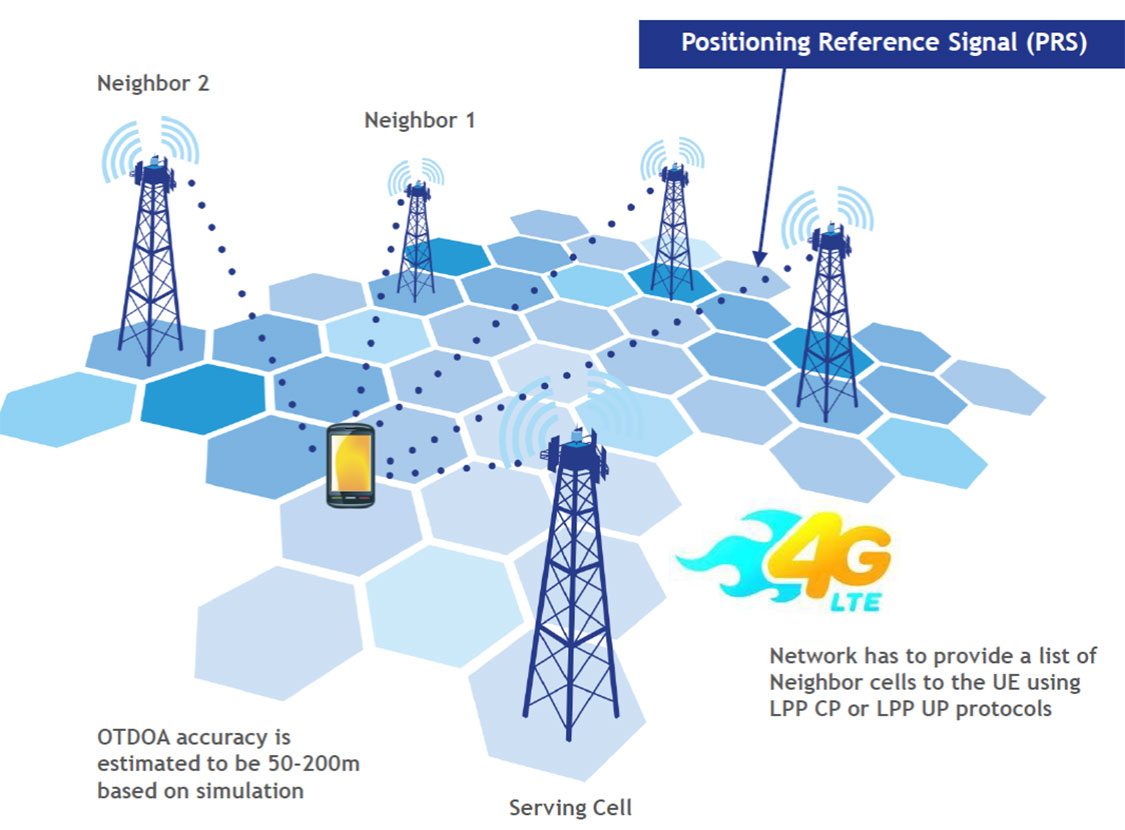
LTE brings a promise of improved location accuracy with new positioning technologies and their integration using hybrid techniques. Although established technologies such as A-GNSS (A-GPS and A-GLONASS) provides excellent performance in environments with a clear view of the sky, performance is often poor indoors, where detection of satellite signals is limited. In LTE, current standards support Observed Time Difference of Arrival (OTDOA), an advanced cellular positioning technology that can augment A-GNSS and provide a more accurate location fix for indoor scenarios.
With large-scale VoLTE rollouts imminent, leading operators are confronted with the need for extensive and complex testing of LTE positioning technologies to ensure VoLTE E911 works well from day one. Additionally, the FCC, whose current E911 regulations apply only to outdoor environments, has proposed stringent indoor requirements as a response to increased mobile usage for emergency calls and lack of accurate positioning information on calls that originate indoors.
“Roughly 70 percent of 911 calls are placed from wireless phones and a majority of these calls originate indoors, so there is a real urgency in providing better location accuracy for mobile users, wherever they are calling from,” said Nigel Wright, vice president at Spirent Communications. “Spirent is currently working with all the key industry players to evaluate OTDOA and its integration with other positioning technologies, and to enable operators to meet the location requirements for VoLTE E911 and the evolving FCC requirements.”
Spirent 8100 LTS has won widespread acceptance as the leading platform for location testing in the wireless industry, and with this latest capability is now able to support OTDOA Position Calculation Function (PCF). Minimum performance testing for OTDOA looks only at the raw measurements from the device, whereas use of OTDOA PCF enables full verification of a device’s position accuracy performance. Recognizing its importance, leading carriers have established their own OTDOA positioning performance requirements beyond bare minimum standards. Ensuring that devices fully meet these requirements as well as the evolving FCC regulations for E911 requires comprehensive testing.
Two satnav superpowers battled it out aboard a superyacht in the Mediterranean this summer, as a spoofing detector designed to differentiate between real and fake GPS signals came to grips with a spoofing device previously responsible for hijacking a sophisticated drone helicopter, deceiving it into landing when it was trying to hover, and for misdirecting the same luxury yacht in tests last summer.
Mark Psiaki, Cornell University professor of mechanical and aerospace engineering, and graduate student Brady O’Hanlon spent a week aboard the White Rose of Drachs, a luxury superyacht, testing their second-generation spoofing detector as the boat cruised from Monaco around the boot of Italy to Venice at the head of the Adriatic Sea. Also on board was a researcher from assistant professor Todd Humphreys’ Radionavigation Laboratory at the University of Texas at Austin. Humphreys tested his latest spoofer aboard the same yacht last year; this year, Psiaki and O’Hanlon embarked for a follow-up experiment to see if they could outsmart the spoofer.
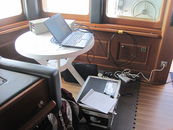
The Cornell team’s spoofing detection system electronics quietly at work detecting evildoers on the bridge of the White Rose.
Both researchers have published earlier versions of their work in GPS World magazine, Psiaki in “GNSS Spoofing Detection,” the Innovation column in the June 2013 issue, and Humphreys in “Drone Hack” in the August 2012 issue.
The former story relates how Humphreys and Psiaki began their investigations as far back as 2008. “There was no intention to help bad actors deceive GNSS user equipment. Rather, our goal was to field a formidable ‘Red Team’ as part of a ‘Red Team/Blue Team’ (foe/friend) strategy for developing advanced ‘Blue Team’ spoofing defenses.”
In international waters this summer, the Cornell and Texas teams could conduct their research unhindered; on land, it’s very difficult to get permission to hack a GPS signal, even for research purposes, Psiaki said.
The Cornell two-antenna system installed on the roof of the White Rose bridge next to the superyacht’s GPS antenna.
Aboard the White Rose, Humphreys’ team initiated an attack of the boat’s GPS receiver, overlaying a disguised false signal on top of the real one, and attempting to send the boat off-course without generating any obvious warning signs. Stationed in a different area of the boat, Psiaki and O’Hanlon’s device set itself to detect the false signals through real-time analysis of their properties, and to provide protection against any attack by issuing a definitive warning whenever false signal characteristics were identified.
“We tested numerous spoofing scenarios,” recalled Psiaki. “We proved the efficacy of the new two-antenna version of one of our spoofing detection systems. It is the functional equivalent of our previous moving-antenna spoofing detection system. With two antennas we can simulate the effects of antenna motion without any need for moving parts. The only problems we encountered were with the initial spoofing drag-off, at which point the true and spoofed signals interfere with each other, and signal tracking can be tricky.
“We recorded wide-band data for all these cases. We think that we know how to enhance our defenses to hold on to the signals and recognizing spoofing during the initial drag-off. We also think that we know how to recover the true signals after an attack. The recorded wide-band data should enable us to develop and test these refinements in the lab, i.e., without the need to go back to sea — not that we would mind having to take another cruise on the White Rose of Drachs.”
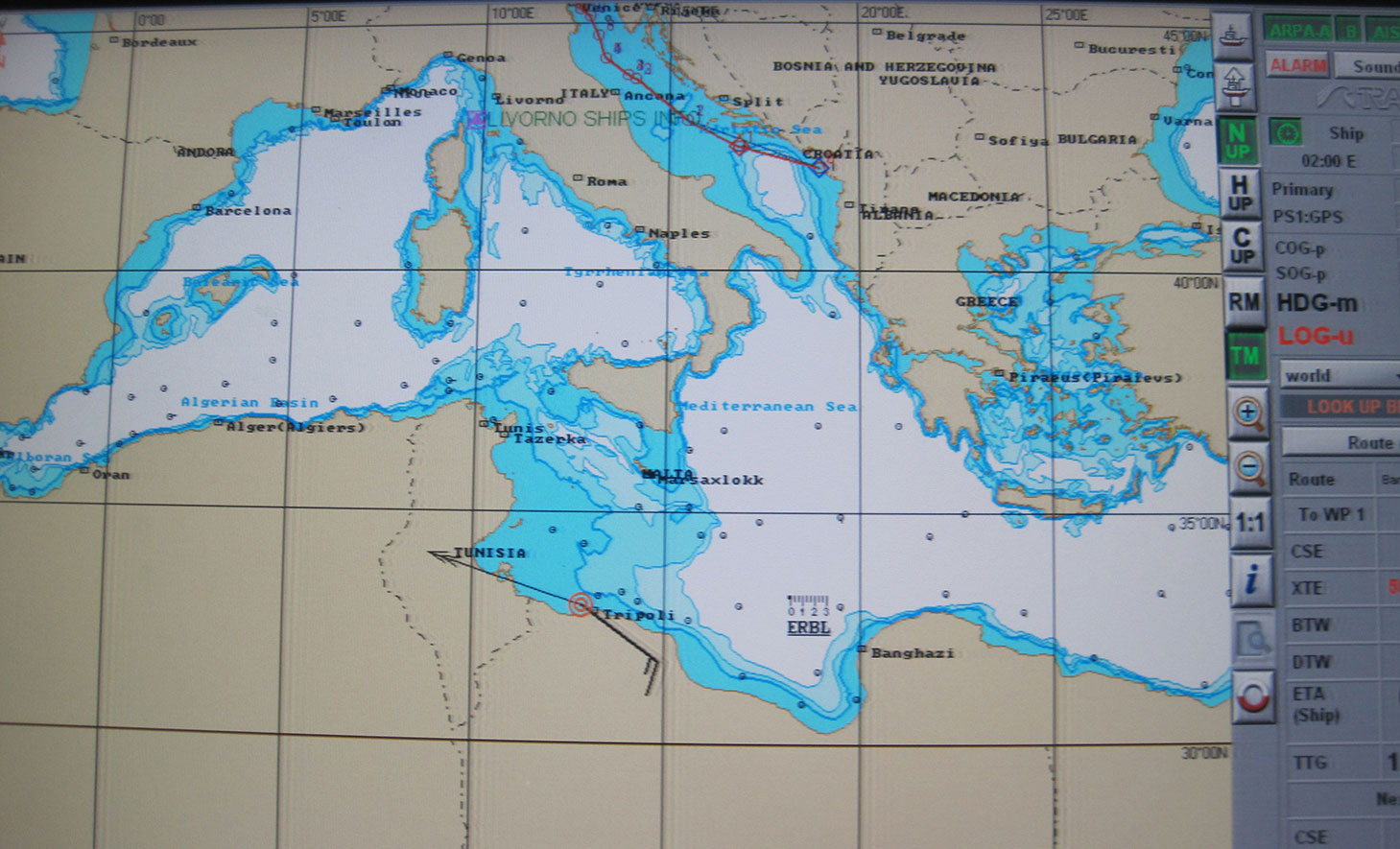
In one test, the yacht’s GPS receiver was spoofed into believing that it was veering off its course, set northwards to Venice, and heading south to Libya at a very high speed. The Cornell detector was able to warn the White Rose’s bridge crew about the attack before the yacht was 20 meters off course.
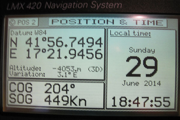
The White Rose’s GPS-driven chart showing it off the coast of Libya (black line) when it was actually in the Adriatic, cruising from Montenegro to Venice (blue line). The spoofing detector knew all along that this was a false reading.“This photo shows the White Rose’ Litton GPS receiver with ridiculous speed and altitude readings — we were in a hurry to get from the Adriatic to Libya and therefore spoofed a straight line route that took us across, actually beneath, Italy and Sicily, at speeds exceeding 900 kts in order to get there in 50 minutes. “
“We want to progress to the point where not only can we tell it’s a false signal, but we can also say, ‘Here is the true signal; here is the true position,’” Psiaki added.
The owner of the White Rose of Drachs, an anonymous businessman, allows the boat to be used for scientific purposes during off seasons.
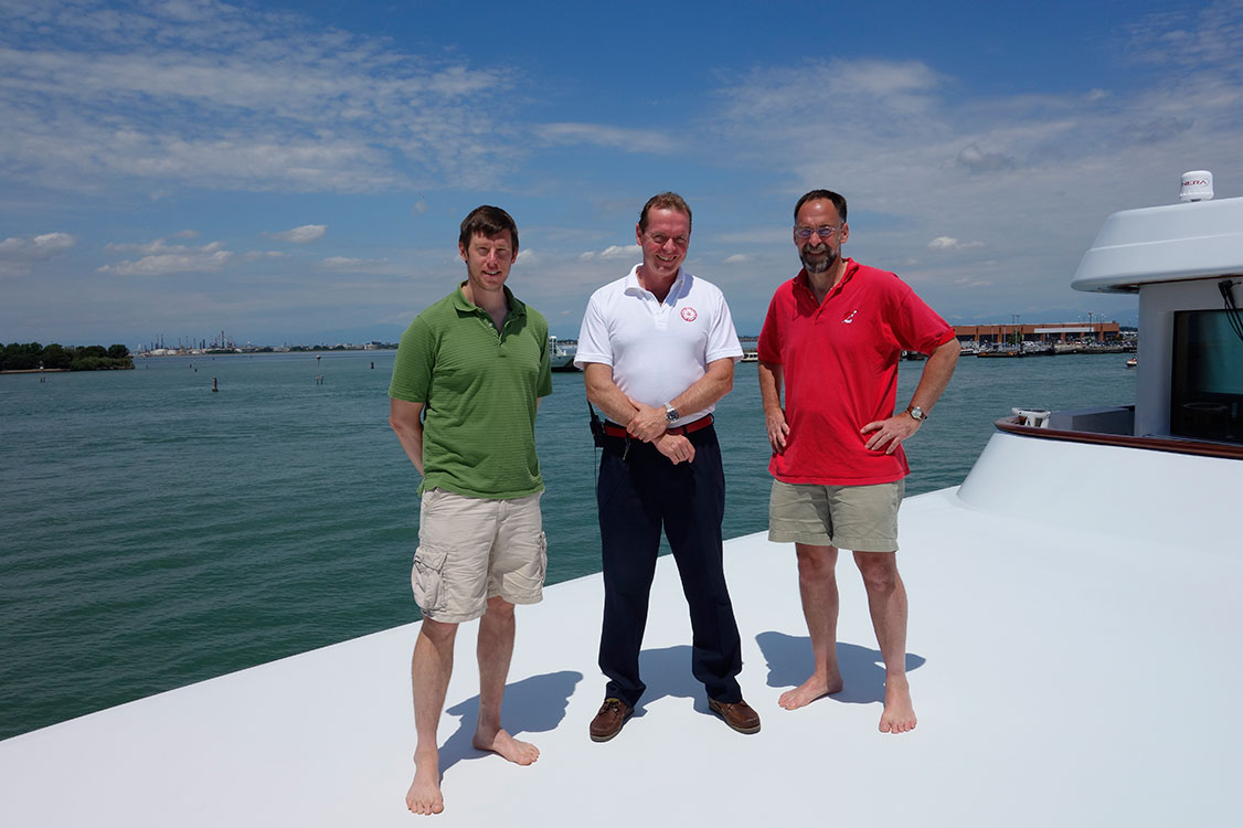
The Cornell and White Rose team: (from left) Brady O’Hanlon, Cornell ECE Ph.D. student, Andrew Schofield, master of the White Rose of Drachs, and Mark Psiaki, Cornell Prof. of Mechanical & Aerospace Engineering.
Psiaki will present a paper on the superyacht experiments at the Institute of Navigation’s GNSS+ conference in September in Tampa, Florida, and GPS World will publish an article based on this paper in the November issue.
This story draws on initial reporting by Anne Ju in the July 28 Cornell Chronicle, with additional material and photos supplied by Mark Psiaki.
“The Advisory Council is comprised of foundation members selected because of their unique expertise, background and reputations within the international navigation and timing community,” said Dana Goward, president of the foundation.
While the council will advise the foundation on an on-going basis, in-person meetings will be scheduled to coincide with those of the U.S. National PNT Advisory Board.
The RNT Foundation Advisory Council membership includes Donald Jewel, GPS World Defense Editor and United States representative; Chuck Schue, also from the U.S.; Refaat Rashad from Egypt; David Last from the United Kingdom; and Krzysztof Czaplewski from Poland.
Mitre’s new Time Anomaly Detection Appliqué (TADA) protects modern digital systems from spoofing attacks that can corrupt time source signals.
Successful spoofing attacks could result in navigational systems going haywire and grounding airplanes, jumbling of buying and selling orders, a shutdown of the stock market, or power-grid failures. Infrastructure and defense systems often rely on GPS’s unencrypted position, navigation, and timing (PNT) signal as their source of accurate time, accurate to about 14 nanoseconds.
The TADA system detects and, for certain users, mitigates timing attacks. “Almost every system has a need for precise and accurate time,” said Darrow Leibner, the Mitre TADA project lead. “Because GPS is accurate and ubiquitous, users have gotten away from implementing other time-keeping methods. That’s where the potential vulnerability comes in.”
TADA is designed to provide a cost-effective, reliable, and easy-to-use method for protecting GPS receivers against spoofing attacks. The system defends against spoofing by continuously comparing a trusted input, such as a known frequency or location, with those provided by the GPS receiver. When a difference between these two inputs is detected, TADA alerts the user to the suspected PNT anomaly.
For a trusted input, TADA uses an atomic clock frequency. For each second measured by the incoming GPS timing signal, TADA counts the number of frequency cycles generated by a Cesium clock. If the incoming GPS signal is valid, TADA will count exactly the expected number of Cesium frequency cycles. If TADA measures a higher or lower number of timing signals than expected, it will display the difference. A difference outside the acceptable margin of error will prompt TADA to alert its users that the GPS timing signal is possibly being spoofed.
In the same way it uses a trusted time source, TADA can also use a known location to detect a spoofing attack. To do this, the user inputs the location of a GPS receiver antenna into TADA. TADA monitors the reported position for any changes. Any reported change of the stationary location would most likely be due to spoofing attack and prompt an alert to the user. Once alerted by TADA to a spoofing attack, users can quickly switch to existing backup systems.
“This is not the invention of the lightbulb,” Leibner said. “Rather, it’s a clever use of existing technologies packaged in such a way that users obtain a greatly increased level of protection for a minimum of investment. None of the TADA components on their own are brilliant. But as one manufacturer said after seeing a detailed description of TADA, ‘It’s brilliantly simplistic.’”
The next stage in TADA’s development is to provide it with the capability to not only detect spoofing attacks, but to mitigate its effects and pinpoint their origin. Mitre will also continue to advocate that to bolster the nation’s infrastructure defenses against spoofing, TADA-like monitoring techniques be included within commercial product design.
The L-band SBAS transponder on the third Luch Multifunctional Space Relay System geostationary satellite, Luch-5V (“v” is the third letter of the Russian alphabet), launched on April 28, has started test transmissions using PRN code 140.
The satellite is positioned at 95° east longitude and completes the Russian three-satellite SBAS constelltion for the System for Differential Corrections and Monitoring. Stations in the IGS tracking network first noticed the signals on July 15, but it wasn’t clear where they were coming from. This is because the satellite is not yet transmitting its position and PRN 140 has also been used by the first Luch satellite, Luch-5A, although it hasn’t been heard from recently. It was expected that Luch-5V would use PRN 141, also assigned for the Luch satellites by the GPS Systems Directorate.
By using the pseudorange measurements recorded by the IGS stations and the orbit positions of both the Luch-5A and Luch-5V satellites derived from NORAD 2-line element sets, it was confirmed that the PRN 140 signals were indeed coming from Luch-5V.
The Luch-5V signals have been noted on a few subsequent days but with a very large clock offset from GPS System Time.
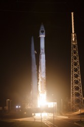
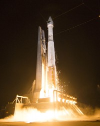
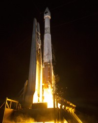
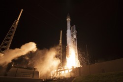
A United Launch Alliance (ULA) Atlas V rocket carrying the seventh GPS IIF satellite for the U.S. Air Force launched at 11:23 p.m. EDT Friday, August 1 (03:23 UTC, August 2), from Space Launch Complex-41 at Cape Canaveral, Florida.
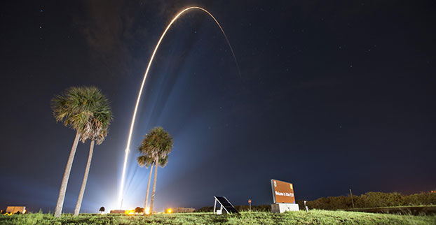
GPS IIF-7 launches into orbit. (Photo credit: United Launch Alliance)
A United Launch Alliance (ULA) Atlas V rocket carrying the seventh GPS IIF satellite for the U.S. Air Force launched at 11:23 p.m. EDT Friday, August 1 (03:23 UTC, August 2), from Space Launch Complex-41 at Cape Canaveral, Florida.The Boeing-built satellite has sent the signals to controllers that confirm it is currently operating properly within the constellation.
Boeing and the Air Force will complete the full on-orbit checkout of the satellite in August. The GPS IIFs offer improved signal accuracy, better anti-jamming capability, longer design life and the new civilian L5 signal.
“We are providing our Air Force partner and GPS users with a steady supply of advanced GPS IIFs,” said Craig Cooning, president of Boeing Network & Space Systems. “Our robust launch tempo requires vigilance and attention to detail, and mission success is our top priority. We continue to partner with the Air Force and ULA to effectively execute the launch schedule.”
GPS IIF-7 is the seventh of 12 such satellites Boeing has built for the U.S. Air Force, and the third on-orbit delivery this year. GPS IIF-8, slated for launch during the fourth quarter, arrived at Cape Canaveral on July 16 to undergo final launch preparations. GPS IIF-7 will join a worldwide timing and navigation system utilizing 24 satellites in six different planes, with a minimum of four satellites per plane positioned in orbit approximately 11,000 miles above the Earth’s surface.
“Congratulations to the U.S. Air Force and all of our mission partners on the successful launch of the Atlas V carrying the GPS IIF-7 satellite,” said Jim Sponnick, ULA vice president, Atlas and Delta Programs. “ULA launch vehicles have delivered all of the current generation of GPS satellites, which are providing ever-improving capabilities for users around the world.”
This mission was launched aboard an Atlas V Evolved Expendable Launch Vehicle (EELV) 401 configuration vehicle, which includes a 4-meter-diameter payload fairing. The Atlas booster for this mission was powered by the RD AMROSS RD-180 engine, and the Centaur upper stage was powered by a single Aerojet Rocketdyne RL10A engine.
The EELV program was established by the United States Air Force to provide assured access to space for Department of Defense and other government payloads. The commercially developed EELV program supports the full range of government mission requirements, while delivering on schedule and providing significant cost savings over the heritage launch systems.
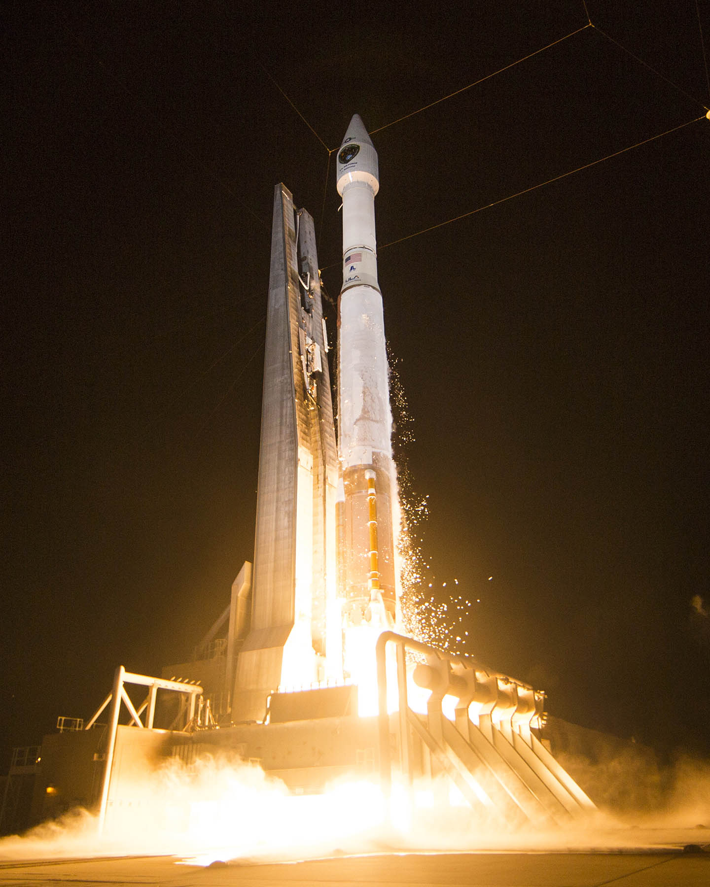
GPS IIF-7 launches into orbit. (Photo credit: United Launch Alliance)
According to Innovation editor Richard Langley, it appears that the satellite will be assigned PRN09, currently unused by the constellation.
The Initial NORAD 2-line element set indicates that the satellite has been launched into the F plane and is drifting towards its assigned orbital slot: