Trimble introduced today new functionality and configuration options for its Juno T41 rugged handheld computer. In addition to a handheld computer and smartphone configuration, the series now includes enhanced, real-time 1-2 meter GPS accuracy and high-speed 1D/2D barcode imaging technology.
The new configurations are in addition to the capabilities already available in Trimble’s Juno T41 handheld computer. All models are built to meet military-grade standards of ruggedness for drops, temperature, altitude, humidity extremes, vibration, chemical exposure and shock with either an IP65 or IP68 rating for water and dust.
“The Juno T41 is truly a workhorse,” said Jim Sheldon, general manager of Trimble’s Mobile Computing Solutions Division. “We designed it for today’s worker who needs a functional field computer that is tougher than any consumer-grade device, while providing easy-to-use features and convenience that people have come to expect.”
All Juno T41 handheld computers feature a 1 GHz processor and 512-MB RAM with either Android 4.1 or Microsoft WEHH 6.5 operating systems. Other standard features include an 8-MP integrated camera, multi-touch capacitive 4.3” sunlight-readable display and 9 PIN Serial and USB ports, all-day battery life and 2-4 meter GPS accuracy capability.
The Juno T41 X configuration is designed to replace Bring Your Own Device (BYOD) smartphones with SMS text and 3.75 cellular data transfer capabilities on GSM networks worldwide.
To increase real-time positional accuracy, the Juno T41 G configuration provides enhanced, 1-2 meter GPS acquisition capability and it can be combined with other Juno T41 configurations, including the smartphone or the 1D/2D Imager.
The Juno T41 G supports the GPS L1 band and offers reliable performance in reduced signal environments. Workers who have to move from place to place to collect remote assets won’t have to waste time waiting for a system warm-up: the Juno T41 G tests at an average cold start of less than 38 seconds, and a warm start of less than 6 seconds. The G configuration handheld collects data in real-time at 1-2 meter accuracy, while also capturing Raw Data Output for post-processing applications. The Juno T41 G is designed to work with Satellite Based Augmentation Systems (SBAS), third-party Real-Time Networks (RTN), and corrections services from Trimble.
Trimble Scan technology in the Juno T41 S reads a variety of traditional 1D barcodes as well as 2D matrix codes, and captures signatures and images. These features are customizable using the Trimble “Scan Agent” application. Enterprises can also use the Software Development Kit (SDK) to optimize applications to meet specific customer needs. Omni-directional reading capabilities along with high-motion tolerance allow for rapid, accurate scanning from virtually any angle or orientation from the handheld to the barcodes.
With these additions, the Juno T41 rugged handheld series has a configuration that can meet a wide variety of business needs in a single rugged device, Trimble said. Users can mix and match the capabilities to create the Juno T41 that is right for their specific business needs: combine the X smartphone with barcode imaging in the Juno T41 XS; add enhanced GPS for the XG. Combine barcode imaging with enhanced GPS and smartphone capabilities in the XGS.
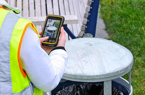
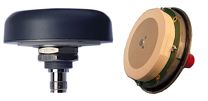
TW3802 Shown with flat radome. Conical radome also available.
Tallysman Wireless Inc. has added the dual-frequency TW3800 series to its high-quality precision line of antenna products.
The TW3800 series antennas feature a circular stacked patch antenna for improved axial ratio, yet are small and light, and have the extended bandwidth required for L1/L2 GPS & G1/G2 GLONASS, the company said. The operating voltage range is from +2.5 to 16 VDC. The antennas have a temperature compensated LNAs and operate from -40 to +85o C to provide reliable performance in most any environment. The TW3800 is packaged in a through hole mount making it suitable for mobile applications.
The TW380x is suited for many applications, including:
Anti-jamming GPS
Mission-critical GPS timing
Military and security
Network timing and synchronization
Precise tracking
High signal availability
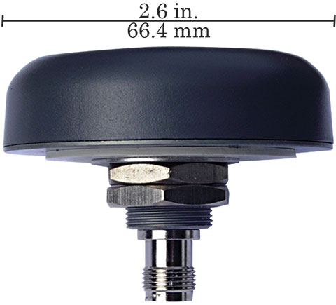
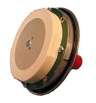
The TW3805 is the OEM version of the TW3802, and can be custom tuned to provide optimal performance inside virtually any housing, Tallysman said.
“The circular patch design of the TW380X antennas permits precision custom tuning with excellent axial ratios.” said Gyles Panther, president of Tallysman Wireless. “This flexibility, combined with the very wide operating voltage enables this antenna to work with virtually any receiver on the market.”
Along with booming auto sales in China has come an increase in auto accidents, which has been a headache for the Chinese government. According to police statistics, most of the accidents in the past couple of years were being caused by new drivers, who have been ignominiously dubbed “road killers.”
One year ago, the China Police Ministry decided to change the method of licensing new drivers by using stricter methods for training and testing. The new system also was designed to avoid cheating.
Under to the new testing system rules, the high-accuracy GNSS receiver became the ideal sensor to enforce the new testing, according to ComNav, a ShangHai-based OEM receiver maker. By offering a turnkey solution, from November 2012 to July 2013 ComNav sold more than 5,000 GNSS OEM boards/receivers for driver testing — the major share of that market.
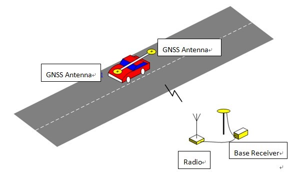
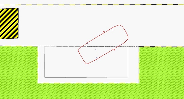
The system uses the real-time kinematic (RTK) method to establish the accurate heading and position of the car, with a ComNav M600 GNSS receiver. A base station sends differential data to a rover installed on the car. With the help of 3G or Wi-Fi, the real-time data is transmitted to the control center. Examiners can then can judge whether the car is in the right area. Both the trainee and system will know the testing results without delay.
Surveying the testing place, marking the testing area, and measuring the car shape need to be done before the installation.
ComNav Technology Ltd. is a high-accuracy positioning solutions supplier that focuses on high-accuracy GNSS core technology R&D, manufacturing and marketing. ComNav is the first Chinese high-accuracy GNSS OEM board manufacturer and producer of a GPS+BeiDou OEM board.
System diagram. Source ComNavSide parking test. Source ComNav
Supergeotek announced that the SuperGIS Toolkit in the newest version of SuperGIS Desktop 3.1a now supports Biodiversity Analysis functions to assist users in comprehending the relationship between distribution of species and spatial pattern.
According to the announcement, biodiversity Analyst in the newest update of SuperGIS Desktop 3.1a provides Diversity Analysis and Landscape Indices and is capable of assisting users in exploring features of spatial patterns of species distributions, including richness, diversity and evenness. Users who have the licensed SuperGIS Biodiversity analyst are allowed to employ Biodiversity Analysis in SuperGIS Toolkit.
INTRUSION SENSORS strive to have a high detection rate and low false alarm rate.
By Eric Olson and Steven Pisciotta
Ongoing threats from terrorist activities at critical facilities require early detection before the threats can reach their target and complete their mission. This has produced the need for advanced security systems to effectively detect terrorist activity, while reducing alarms caused by normal friendly activity. Automatic Threat Assessment, also referred to as Identify Friend or Foe (IFF), is the ability to automatically acknowledge alarms created by friendly assets. It can be achieved with a security system that uses GPS and geospatial data to go beyond the typical intrusion-sensor-only configuration.
The addition of a tracking system associated with friendly vehicles and personnel can provide the missing information necessary to tighten security and reduce the need to take action on alarms caused by friendly targets, and reduce the material and personnel cost of threat assessment. Tracking systems and intrusion sensors can worktogether to automatically classify an actual intruder with high confidence and without operator intervention.
The Verification Problem
Typical intrusion sensors include intelligent fences, ground proximity sensors, radar, LIDAR, and video analytics. The role of the intrusion sensor is to identify a breach and notify security personnel so they may perform verification. Table 1 shows the formal alarm types received from intrusion sensors, which strive for a high detection rate and a low false-alarm rate. For this reason, the nuisance alarm can be problematic as it reflects a real event for the intrusion sensor, but often a non-event for the security operator.
These typical sensors only provide a “suspected intruder” list. The follow-on task is to decide whether or not to reclassify a suspected intruder as an actual intruder. This process is typically a manual task and can be difficult, confusing, and time-consuming.
For instance, a landscape crew will trigger alarms. Even for very accurate systems that can uniquely track the object over a long period, it is highly likely that over the period of time the landscapers are in the area, the track will be lost, causing the system to re-alarm on the same person or vehicle, as it represents a potential intrusion.
If the landscaping crew needs to open a gate, and that gate is integrated into the facility’s access control system via a dry contact or beam breaker device, it may continuously alarm while left open, or at a minimum, in the case of the beam, each time one of the workers or the vehicle passes through the entrance. In these situations, security will either need to validate each alarm by verifying it on a camera or having an officer follow the landscaping crew throughout their route.
The existence of a friendly alarm event that needs continual validation can lead to compacency of security personnel, either not verifying it, or not verifying it in a timely manner.
Table 1. Alarm types.
Combined Detection, Location
A GPS tracking system combined with the intrusion sensors can help identify friends. Tracking systems consist of two main types of locating devices: GPS-enabled devices and wireless transponders.
Modern, low-cost GPS receivers can achieve an accuracy rating of less than 3 meters, provide an update once per second, and do not require visibility to the open sky. Wireless communication transmits the GPS data to the C2 system. A typical data set includes time, date, latitude, longitude, altitude, heading, speed, and quality of GPS signal.
The combination of intrusion sensors and tracking systems can produce automatic threat assessment. Routine situations requiring significant security involvement, such as the landscaping scenario, can be automatically managed by the system. The command and control system has the ability to know friendly targets and their location.
Further, the system can perform a check before actually alarming. In the case of a perimeter alarm, it now has the intelligence to understand, within a level of confidence, that the object detected by the intrusion sensors is the same friendly item being tracking by the tracking system. If the system determines the targets to be the same object, the alarm can be suppressed, eliminating the need for security to verify the event.
THE COMBINATION of intrusion sensors and a tracking system allows for Automatic Threat Detection.
Common Operating Picture
The integration of these types of systems is not complex in terms of how to coordinate data. Interface documents exist for these types of integration and are done on a regular basis. Typical position and target information is communicated over XML in a standard format. However, to gain these benefits, the tracking systems and intrusion sensors must all work within a common geospatial operating picture.
Advantages of geospatial or geo-referenced systems systems include the ability to easily display and control data in a map-based format, allowing tracking systems and intrusion sensors to synergistically perform automatic verification. This combined knowledge of the target’s track also allows the fusing of the GPS data and the intrusion sensor data into a single object and path, aiding security by reducing target and track clutter on his command and control or PSIM (perimeter security information system).
Take for example a guard enabled with a tracking device, performing a tour around a fence protected by video analytics enabled cameras. On a typical PSIM, a normal guard tour would result in two icons on the display, one friendly from the tracking system and one unknown from the video analytics. This scenario would also result in two similar object tracks. Security would need to review the situation and understand that this symbology represents a single target and a single track.
Integrating the tracking system with the video analytics system allows for a fusing of this data, and the resulting command-and-control symbology is a single target and a single track.
Other considerations when combining a tracking system with intrusion sensors include update rate, time and location accuracies, and overlapping coverage.
Ideally, all sensors would be synchronized when it comes to timing aspects, but this is typically not the case. Different timing between data updates and time inaccuracies can result in the inability for the systems to confidently conclude that two tracks were created by the same target. Transport delay, the transmission of the GPS data through the satellite, can also be an issue. For tracking devices, it’s vital for the data to be received by the C2 system with a repeatable transport delay. Variability in the transport delay also decreases the ability to automatically verify the threat.
Geographic accuracy of both the GPS tracker and the intrusion sensor is another important factor in data fusion. Typical GPS trackers have an accuracy rating of 3–10 meters. Actual accuracy varies based upon the visible GPS satellites, tall buildings, body worn, and RF interference. Intrusion sensors also possess an inherent accuracy. Radar surveillance may have a resolution of 1 x 1 meter at close range, but it expands at far range to 1 x 20 meters.
Intelligent fence sensors and video analytic systems can have resolutions that vary from 1 to 25 meters, based on the type of sensor and the terrain. These geographic inaccuracies can be handled to some degree by considering other factors, including heading, speed, and previous track, but it’s important to understand where these inaccuracies can occur.
Overlapping coverage of surveillance sensors also affects data fusion. In the case of track fusion, this ability is only available is areas where both a geospatial intrusion sensor exists and a tracking system is operational. If there are gaps in overlapping coverage, or areas that do not include geospatial- based intrusion sensors, then fusion is not possible in those regions.
Eric Olson is vice president of Marketing at PureTech Systems.
Steven Pisciotta is president of Remote Tracking Systems.
Ria Novosti reports that Russia will launch two GLONASS navigation satellites later this year to make up for the loss of three satellites in the recent Proton rocket explosion after launch from the Baikonur space center in Kazakhstan, according to a senior space industry official.
“We are planning to launch two satellites from the Plesetsk space center [in northern Russia] to replenish the GLONASS orbital grouping following the recent Proton-M accident,” said Nikolai Testoyedov, the head of the Information Satellite Systems (ISS) company, which manufactures satellites for the GLONASS project.
The first GLONASS is scheduled for launch in the beginning of September, and the second at the end of October, according to Testoyedov. The official added that both satellites will be launched on board the Soyuz carrier rockets, which has proven to be more reliable than ill-fated Protons.
A group of 29 GLONASS satellites is currently in orbit, with 24 spacecraft in operation, three spares, one in maintenance, and one in test flight phase, according to Russia’s space agency, Roscosmos.
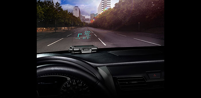
Garmin International Inc. has announced HUD, the company’s first portable head-up display for smartphone navigation apps. With the HUD display, drivers can view navigation directions projected onto a transparent film on the windshield or an attached reflector lens. Garmin said by providing comprehensive road guidance at a glance and right within the driver’s line of sight, HUD can help increase safety and reduce driver distraction.
HUD receives navigation information from a Bluetooth-enabled smartphone running a Garmin StreetPilot or NAVIGON app.
“Head-up displays currently have their place in select high-end cars, but HUD makes this technology available as an aftermarket accessory for any vehicle, at an affordable price,” said Dan Bartel, Garmin vice president of worldwide sales. HUD has an MSRP of $129.99. Garmin StreetPilot and NAVIGON apps, starting at $29.99 for a regional map (NAVIGON U.S. Central, East or West), provide premium turn-by-turn navigation for smartphones, including onboard maps, lane guidance, speed limit warnings, real-time traffic, and other features.
HUD offers more navigation details than other portable head-up displays, yet presents them in a simplified way that doesn’t divert the driver’s attention from the road, Garmin said. The directions are easy to follow and allow drivers to navigate even the most challenging interchanges and traffic situations with ease. HUD displays turn arrows, distance to the next turn, current speed and speed limit, as well as estimated time of arrival. It even lets drivers know what lane to be in for the next maneuver and alerts them when they exceed the speed limit, the company said. HUD also warns users of potential traffic delays and upcoming safety camera locations. The crisp display automatically adjusts the brightness level so projections are clearly visible in direct sunlight or at night.
Complementing the visual display, spoken turn-by-turn directions are provided simultaneously by a compatible Garmin or Navigon app, either through the smartphone speaker or a Bluetooth-connected car stereo. Music streamed to the car stereo from the smartphone will automatically fade out for turn-by-turn voice prompts. HUD also continues to display navigation information while taking incoming calls.
Users can choose between displaying HUD navigation information on their windshield, with the included, transparent film, or on to the included reflector lens that attaches directly to HUD. The device pairs wirelessly with a compatible Bluetooth-enabled iPhone, Android phone or Windows Phone 8. An integrated USB port on the vehicle power/adapter cable makes it easy to charge the smartphone while driving, Garmin said.
If you were able to attend the webinar “Nightmare on GIS Street: GNSS Accuracy, Datums and Geospatial Data” held on June 20, thanks for attending. If not, you can view the webinar here. We had a world-class panel of experts discussing the nightmare of accurately combining different sources of geospatial data as well as on-the-fly datum transformations in the field when using high-precision GPS/GNSS receivers.
Let me apologize in advance if it seems like I’m “beating a dead horse” in writing about this issue. I intended to address the questions raised during the webinar. After addressing one of the first issues below (WGS-84), I expended my allocated space and energy. Rest assured I will publish answers to the other questions that were raised before and during the webinar.
Very few of the geospatial software vendors (GIS or surveying) are handling horizontal datum transformations correctly or in a manner that is easy for the average GIS operator to understand. The good news is that hopefully we’re raising awareness and some are responding, such as Carlson Software. Carlson recently released version 3.0 of their SurvCE surveying software for GNSS data collection. It includes a 14-parameter transformation from ITRF08/WGS-84 G1674 to NAD83/2011. You might want to watch the four minute video below demonstrating the transformation process in SurvCE 3.0. You’ll see the difference after the transformation is about two tenths of a foot (~6cm). If I were to guess, I would say majority of the difference after the transformation is the tectonic plate movement that is unaccounted for. Reconciling the tectonic plate movement is difficult because you need to have an accurate velocity (movement) model for the software to reference. In some geographic areas, the movement is minor (1mm per year) while other geographic regions move 6cm per year or more. Lastly, what if there’s a major earthquake such as the 2011 earthquake off the coast of Japan or the 2010 earthquake off the coast of Chile. During those events, the ground shifted many meters in some cases.
Source: Michael Dennis – US National Geodetic Survey
I’d like to spend a little time on the subject of the WGS-84 reference frame. It’s a term that’s used and abused a lot, including by myself on occasion.
Taking a Look at the WGS-84 Reference Frame
First, let me begin with the statement that WGS-84 should not be in your geospatial vocabulary. In fact, I’ve been corrected in the past that it is actually a reference frame rather than a datum, but you’ll likely see it listed as a datum in your geospatial software.
WGS-84 is not something you’ll find physical marks on the ground that you can use to verify GNSS equipment performance. WGS-84 is defined by the U.S. National Geospatial-Intelligence Agency (NGA), which serves the U.S. Department of Defense and the U.S. Intelligence Community. In other words, one of its roles doesn’t include serving the civilian community. Originally, the accuracy of data referenced to WGS-84 could not be defined more accurately than a couple of meters. In fact, the definition of WGS-84 has changed several times over the years, usually without your knowledge, and usually not accounted for in the geospatial software you are using.
Originally (1987), the Department of Defense transformation values between WGS-84 and NAD83 (dX, dY, dZ) were set to 0, which led people to believe they were considered the same. A footnote that was largely ignored is that the standard deviation of the WGS-84 to NAD83 transformation values was ~2 meters (Doyle, D., 2013 email). The bottom line is that if someone hands you a GIS dataset and says it’s referenced to WGS-84, an alarm should immediately sound in your brain prompting you to query the presenter of the data. When and how was the data referenced to WGS-84? Likely, they won’t know the answers to the questions you ask. In that case, you have no choice but to tag the data as only accurate to two meters, at the very best. Of course, if it was data collected by a consumer-grade GPS unit, the accuracy is likely much worse.
The history of WGS-84 is as follows:
——————————————————–
WGS-84 (Original) – 1987
Aligned with NAD83/86 (original) but standard deviation of the transformation was +/- 2 meters.
——————————————————–
WGS-84 (G730) – 1994
Aligned with ITRF91 (epoch date 1994.0). A significant shift took place with this adjustment.
As you can see from above, if someone hands you a dataset and states it’s in WGS-84 format, it begs the question of “which one?”, not unlike the same question you should ask if someone states a dataset is “NAD83”
As I mentioned above, while the 14-parameter transformation to move from one datum to another is not commonplace in geospatial software yet, but it’s gaining traction and it’s not difficult to implement. The trickier, and more difficult variable to reconcile is the tectonic plate movement. It may not seem like the earth you stand on is moving very much, but years of movement can add up when you’re using GNSS equipment capable of 1-2cm accuracy.
Example: Let’s say you’re using OmniSTAR’s HP real-time correction service. The accuracy of that service is rated at 10cm horizontal 2DRMS. OmniSTAR informed me that their system is referenced to ITRF08 using the current epoch date (eg. the date you collect the data). Let’s say your GIS basemap is referenced to NAD83/2011 (epoch 2010.0), which is the most current version of NAD83 (I apologize to non-US readers for this example, but you likely have a similar situation). The 14-parameter transformation will transform your data from ITRF08 (current date epoch) to NAD83/2011 (current date epoch), but then you have to account for the tectonic plate movement from current epoch date (assume 2013.5) to 2010.0. That’s 3.5 years of crustal movement. The tectonic plate movement in some parts of the US are only 2mm/year so 3.5 years x 2mm/year = 7mm. Since OmniSTAR’s HP service is 10cm, you could say that 7mm of plate movement is below the noise floor. However, let’s say you’re in California where the tectonic plate movement is 5cm/year in some places. Reconciling the tectonic plate movement in that environment becomes important when you think about 3.5 years x 5cm/year = 17.5cm!
So, when populating your GIS database, especially with “high-accuracy” data, it’s important to understand not only the datum the incoming data is referenced to, but also the epoch date the data is referenced to. An answer of “WGS-84” is not good enough and probably not accurately represented in the geospatial software you’re using. More than likely, ITRFxx is more accurately defined in your software, if it is present.
Regardless, WGS-84 should not be in our geospatial vocabulary, or at least be quickly fading.
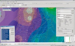
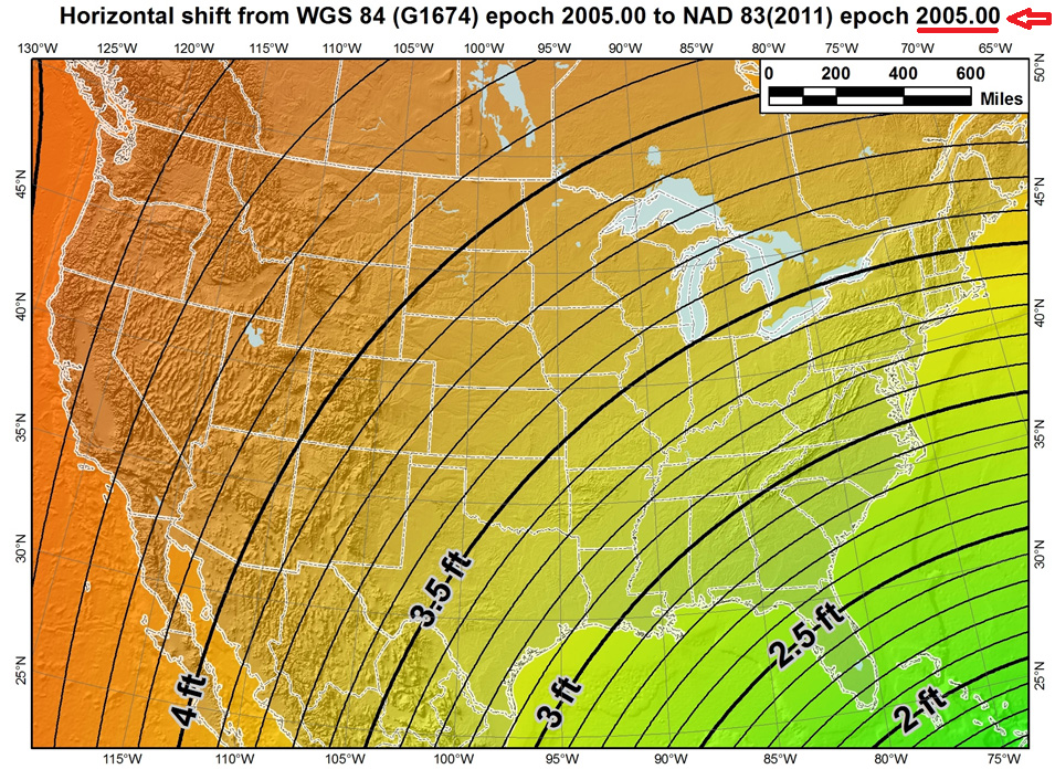
To illustrate the effect of tectonic plate velocities, please view the following two images:
The first image shows the the difference between the latest definitions of WGS-84 (G1674)/ITRF08 epoch 2005.0 and NAD83/2011 epoch 2005.0. Notice the smooth contour lines. This is using the 14-parameter transformation.
Source: Michael Dennis – US National Geodetic Survey
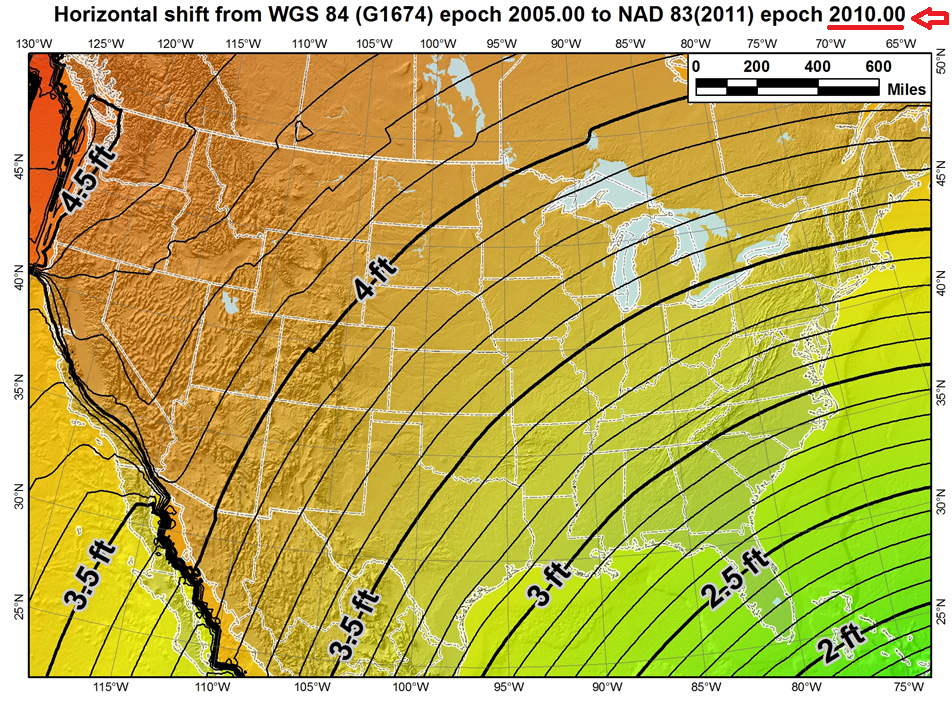
However, the correct US definition of NAD83/2011 is referenced to epoch 2010.0, a full five years later than the first image where it was referenced to 2005.0. Notice the dramatic effect of the tectonic plate movement in the western part of the US. In this case, the 14-parameter transformation was used as well as the velocity model to estimate the tectonic plate movement.
Source: Michael Dennis – US National Geodetic Survey
This illustrates that increasingly, geospatial data consumers will need to consider that “time is of the essence” when combining geospatial datasets.
GLONASS Rocket Crash
On July 2, 2013, a rocket carrying three GLONASS satellites crashed shortly after lifting off from its launch pad in Kazakhstan’s Baikonur cosmodrome. It’s the second launch crash for GLONASS, costing Russia six GLONASS satellites in the past three years. According to several sources, the cause of the July 2 crash was blamed on incorrectly installed angular velocity sensors. Despite the loss, GLONASS still has a full constellation of 24 satellites and, since GLONASS is largely used as an augmentation to GPS, people using GPS/GLONASS receivers should experience no change in performance.
Rumors are circulating that this crash signals the beginning of the end of the GLONASS program, but I don’t believe it. Although this crash is a serious blow to Russia’s space program and will certainly set back the GLONASS program due to the nature of the crash (at the launch pad), I believe that GLONASS is here to stay.
GPS suffered a major setback when, in 1986, the Space Shuttle Challenger exploded 73 seconds after lift-off because the space shuttle was the planned launch vehicle for GPS satellites. Subsequent launches were shifted to the Delta II rocket, causing a two-year delay in GPS satellite deployment. However, GPS never subsequently strayed from its course and for nearly three decades has been the so-called gold standard of satellite-based positioning, navigation, and timing.
с надеждой (here’s hoping) GLONASS can similarly recover its momentum and progress as planned.
Update: On July 9th, Ria Novosti reports that Russia will launch two GLONASS navigation satellites later this year to make up for the loss of three satellites in the recent Proton rocket explosion after launch from the Baikonur space center in Kazakhstan, according to a senior space industry official.
“We are planning to launch two satellites from the Plesetsk space center [in northern Russia] to replenish the GLONASS orbital grouping following the recent Proton-M accident,” said Nikolai Testoyedov, the head of the Information Satellite Systems (ISS) company, which manufactures satellites for the GLONASS project.
The first GLONASS is scheduled for launch in the beginning of September, and the second at the end of October, according to Testoyedov. The official added that both satellites will be launched on board the Soyuz carrier rockets, which has proven to be more reliable than ill-fated Protons.
A group of 29 GLONASS satellites is currently in orbit, with 24 spacecraft in operation, three spares, one in maintenance, and one in test flight phase, according to Russia’s space agency, Roscosmos.
Join me on the NSPS Radio Hour – Monday, July 22, 11:00am US Eastern Time/8:00am Pacific Time
I, along with Michael Dennis of the US National Geodetic Survey, will be guests on the National Society of Professional Surveyors (NSPS) radio hour talking about interesting geospatial data and GNSS subjects. You can tune in live or download the mp3 audio recording onto your smartphone or mp3 player. Feel free to send me an email ahead of time if there’s a particular subject you’d like to hear us discuss.
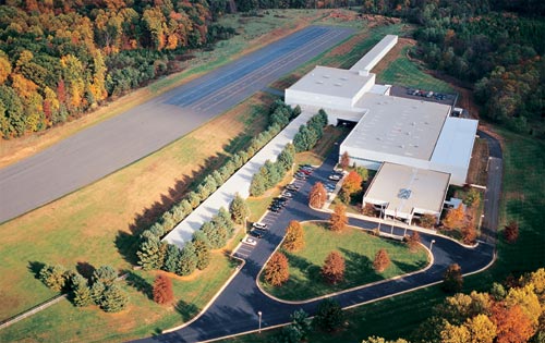
The Insurance Institute for Highway Safety (IIHS) has contracted Locata to provide local, ground-based precision positioning signals for vehicle testing in a new $30-million expansion at the famous Vehicle Research Center, focused on vehicle automation testing. A novel indoor section of the expansion will allow replication of parking garages and urban canyons — where GPS will be largely masked — and will enable evaluation of technologies such as forward collision-avoidance systems in adverse conditions.
Used to be that changes to equipment in and on cars took decades to enter production. As an example, just how long did it take to get headrests/restraints into most vehicles? Restraint patents were originally filed in 1921, and people started to get interested in putting them in cars in the 1950s, but they didn’t start to show up in vehicles until the 1960s and weren’t mandated until 1969 in the U.S. Since then, the rate of technology adoption by the automakers has accelerated.
Now, it seems that almost every new car has Internet, Bluetooth phone, GPS navigation, rain-sensing wipers, touchscreen, automatic foot sensing/hand waving/touch sensitive lift-gate/door-locks/touchscreens, and even massaging seats and automatic seat positioning… And safety devices galore, including multiple air-bags and anti-lock braking systems, rear-view cameras, intelligent speed adaptation, and now even lane-departure and forward collision mitigation/collision avoidance systems.
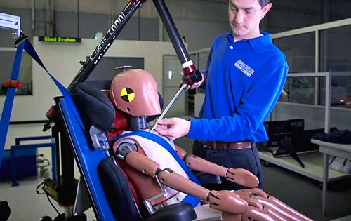
Safety has finally become a major selling feature on almost every make and every model, thanks in large part to organizations like the Insurance Institute for Highway Safety (IIHS) and the Vehicle Research Center (VRC) near Washington, D.C. The VRC is the principle location for U.S. vehicle crash testing that we see regularly on TV and YouTube videos with crash-test dummies being bashed around in all sorts of simulated vehicle accidents. These tests have led to significantly enhanced safety features in today’s vehicles.
Instrumented crash dummy preparation. Photo: IIHS
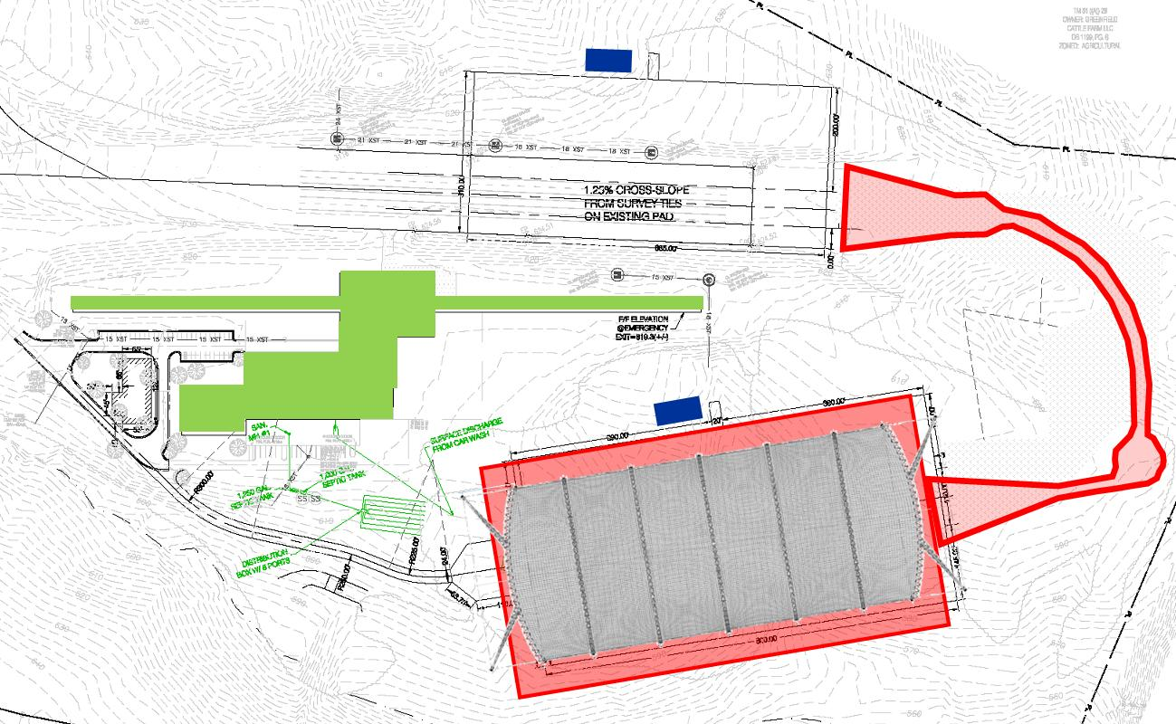
Automation in vehicles, particularly automation of safety devices, is seen as the next most promising phase of vehicle safety improvement. And as these safety devices become more complex, they need to be verified in realistic conditions. Hence, the VRC is now undertaking a major expansion of its testing capabilities with the addition of a continuous vehicle test track that transverses not only open-air roadway areas, but also includes a 300-foot by 700-foot fully covered testing area.
Covered test track section expansion. Photo: IIHSExterior test track links new VRC facilities. Photo: IIHS
The $30 million upgrade will include a Locata supplied LocataNet, which will provide the VRC with high-precision positioning to enable rigorous, consistent and repeatable scientific evaluation of new vehicle crash avoidance systems. Along with the cm-level positioning provided by the Locata network, VRC is also working on state-of-the-art robotics to enable the required level of testing precision. The LocataNet will furnish the IIHS with a locally controlled positioning system that is seamless over all the VRC test areas, including extremely accurate and consistent automated positioning of vehicles.
In the covered enclosure, VRC intends to set up collision avoidance testing for areas such as parking garages and urban canyons — areas where GPS is either not available, or is degraded to a level where positioning is intermittent or isn’t available. Locata will provide a consistent level of accuracy and reliability that the VRC requires for these GPS-degraded scenarios.
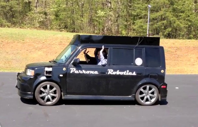
The VRC site currently looks very much like a construction site with the track extensions under way and the under-cover area just starting to be built. The VRC facility will come online in two stages — the outdoor track before the end of the year and the indoor around early Q2 next year. Locata engineers have been working with Perrone Robotics on very early integration testing. Perrone is contracted to deliver a system for testing vehicle safety systems in the test vehicles that IIHS is testing. For the first phase, the system includes a robot target vehicle with the footprint of a car, but only 4 inches high and 1 inch of ground clearance. If the vehicle being tested fails to prevent a collision with the robot target vehicle, the test vehicle runs over the robot target vehicle, dislodging a soft target, but avoiding damage to the test vehicle, robot target vehicle, or soft target.
(For a feature article on the Perrone Robotics soft-target unmanned ground vehicle and drop-in actuator kit, see the upcoming August issue of GPS World magazine.)
To ensure that the test vehicle drives repeatedly, the system also includes a drop-in actuator kit that can be installed into any test vehicle in 30 minutes or less. The system is designed to allow a human driver to sit comfortably in the vehicle and drive, but is also capable of controlling the throttle, brake and steering to drive test profiles. Perrone is using Locata as the positioning system. In addition to alleviating concerns about GPS outages or dead/weak signal spots, it also allows the system to be operated on the new, covered IIHS test track currently under construction.
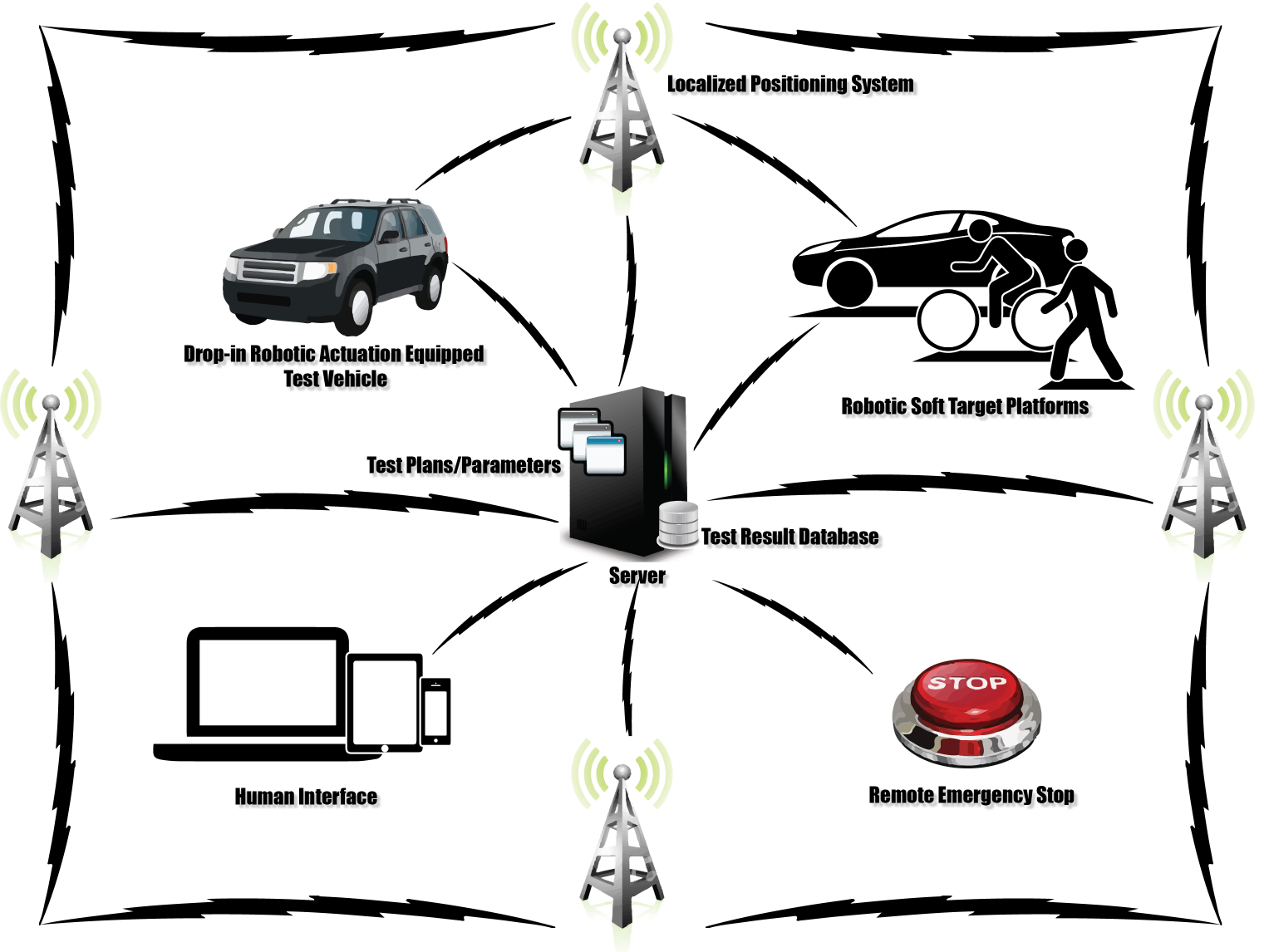
DARPA Urban Challenge Peronne Robotics car. Photo: IIHSVRC robotic system using Locata positioning. Photo: IIHS
The Locata network has been running from ground-based tripods scattered around the track wherever construction will allow. IIHS will construct 30-foot masts on which to place Locata antennas, but even that is still several months away.
Locata’s autonomous positioning technology uses terrestrial networks that function as a “local ground-based replica” of GPS-style positioning. Locata works with GPS, but can also operate independently when GPS is not robust or is completely unavailable. Instead of orbiting satellites, Locata utilizes a network of small, ground-based transmitters that blanket a chosen area with strong radio-positioning signals. Because it is terrestrially based and provides relatively high power signals, Locata works in any internal or external environment.
A fundamental requirement for radio-positioning systems is nano-second-level synchronization of all transmitters in the positioning network. In the past, multiple atomic clocks were used to achieve this level of synchronization. Instead, Locata’s technology relies on a patented synchronization method called TimeLoc, which allows Locata to replicate GPS in a ground network.
Locata’s technology encompasses both the transmit and receive sides of the positioning network, allowing the system to be configured to meet specific, localized demand for availability, accuracy and reliability. This flexibility ensures that signal integrity can be guaranteed in even the most demanding environments — especially indoors, like the covered test track section of the expanded VRC.
Locata has also made significant progress in North America with the recent award of a contract to instrument the White Sands Missile Range to Locata’s partner TMC Design.The 746th Test Squadron’s new non-GPS-based positioning system is expected to be operational by Q3 2013, with a network that covers 2,500 square miles (6,500 square kilometers).Locata technology will provide the USAF’s “gold standard GPS truth system,” supplying continuous centimeter-level, independent positioning when GPS is completely jammed. This award followed several months of U.S. Air Force testing and evaluation of an initial LocataNet installation at the White Sands facility.
So, following the recent IIHS endorsement of the Locata technology for use at the VRC, Locata appears to be well on the way to acceptance as a reliable truth system for use alongside GPS. Along with other mining-related installations elsewhere in the world, it would seem that we are no longer in evaluation mode; rather, we should anticipate other future Locata production installations.
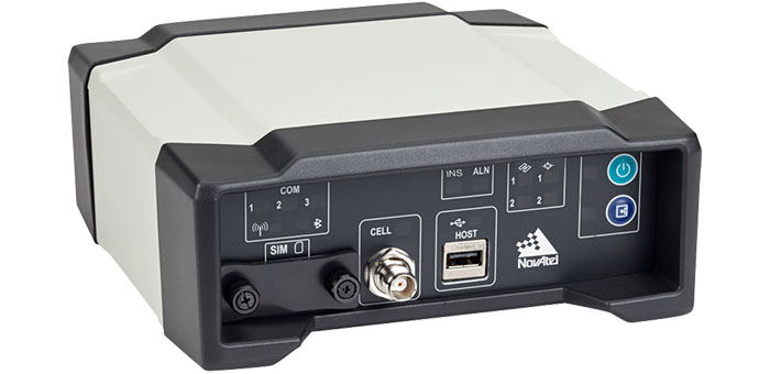
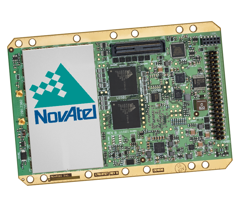
NovAtel has announced two new GNSS receivers: The OEM638 high precision receiver card and the ProPak6 enclosed receiver. The two products incorporate NovAtel’s most advanced GNSS technology, the company said.
Novatel OEM638. Photo: NovAtel
The most advanced card within NovAtel’s OEM6 GNSS receiver family, the OEM638 tracks all existing and planned constellations including GPS, BeiDou, GLONASS, Galileo and QZSS. By providing flexible positioning options, from standalone meter-level to AdVanceRTK centimeter-level accuracy, the OEM638 offers the flexibility to meet a wide range of positioning requirements. A powerful API, 4-GB on-board data storage, wide input voltage and a host of interface options simplifies integration, decreasing time to market and overall system costs, NovAtel said.
“With the addition of the OEM638 GNSS receiver card, NovAtel’s OEM6 product line offers an even wider range of positioning options on our standardized technology platform. With three compact form factors to choose from, the OEM6 product line gives us the ability to meet the unique size, weight and performance requirements of our customers,” said Jason Hamilton, director of marketing for NovAtel.
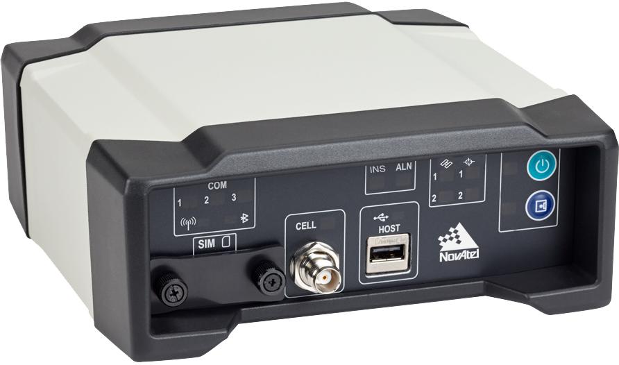
The ProPak6 is NovAtel’s most sophisticated GNSS enclosure product, offering meter-level to centimeter-level positioning in a rugged, water resistant IP67 housing. Standardized software and hardware connections, including multiple RS-232/RS-422 serial ports, CAN Bus, USB host and device, as well as Bluetooth, Wi-Fi, and optional cellular radio, speeds time to market and maximizes user capabilities, the company said. The ProPak6 is designed for reference station, timing, and general position applications.
NovAtel ProPak6. Photo: NovAtel
“Our ProPak6 provides a powerful enclosure option for integrators looking for positioning flexibility, multiple communication options and Ethernet support for remote configuration and access of data logs,” Hamilton said. “It was designed to simplify the integration process, by accelerating time to market and ensuring maximum return on investment. ”
The OEM638 and ProPak6 will be available to order July 26, with shipments beginning in August.
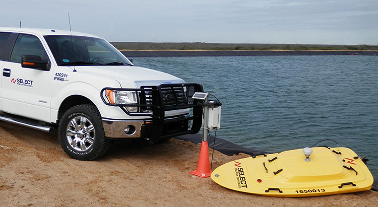
Proper management of large volumes of fluid has become a necessity as hydraulic fracturing has increased throughout North America. Creating the most effective fluid handling solution involves environmental, cost and project timeline considerations.
Select Energy Services, LLC, has launched AquaView, a suite of services that efficiently monitor water at various stages of the project through real-time, wireless technology. AquaView’s instant monitoring capabilities allow Select to respond immediately to on-site issues before emergencies arise.
AquaView capabilities include pit and reservoir hydrographic surveys utilizing SONAR remote control and GPS real-time data; data delivered to a secure portal offering current and historical data; real-time water quality reporting; and mapping and geographic information systems (GIS) support. The system can transmit the data with enabled access through computers, smartphones, tablets and text messages.
“This new technology is changing the way our industry does business,” said John Schmitz, Select Energy Services CEO. “AquaView will reduce down time and assist in the maintenance of completion schedules, essentially removing the need for traditional water tracking and measurement systems.”
Select’s team is capable of water transfer, containment assembly, water fill and complete removal or disposal.
Geotab has launched a telematics Near Field Communications (NFC) Driver ID solution using an Input-Output-Expander (IOX) that allows for simultaneous connections and communications to occur with multiple devices, such as Garmin, Iridium, and HOS.
As an addition to its comprehensive fleet management platform, the technology will now help managers keep better track of each driver’s productivity and on-road safety — no matter which vehicle they are in, Geotab said.
With one touch of the NFC fob, vehicle operators can quickly, easily, and securely transfer their driver identification information to the cloud. Since Geotab’s GO6 device allows for multiple plug-and-play connections, the NFC Driver ID solution can be setup in minutes, the company said. Associating drivers with the vehicles they are in also allows for the software to generate driver-based score reports.
“The newly launched NFC Driver ID is a telematics industry game-changer that provides a reliable and accurate solution for businesses which pool their vehicles,” said Colin Sutherland, Geotab VP.
“NFC is seeing rapid application expansion across smartphones, tablets, and laptops. We fully expect to leverage this technology for future applications,” added Neil Cawse, Geotab CEO.
Although Geotab is launching a new Driver ID solution based on NFC, Geotab’s web-based software, MyGeotab, has been reporting both driver and vehicle summary value reports for over 10 years. The NFC Driver ID solution is now available for purchase through Geotab’s extensive Authorized Reseller network.