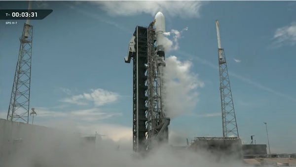
SpaceX successfully launched the GPS III SV-08 satellite into orbit on May 30 from Cape Canaveral Space Force Station, marking a significant milestone for the U.S. Space Force’s rapid-response capabilities. The mission, executed in close coordination with Lockheed Martin and SpaceX, launched the eighth GPS III satellite into the constellation after an accelerated preparation period of just three months, well ahead of the traditional two-year timeline for national security launches.
The GPS III SV-08, named after the pioneering NASA mathematician Ms. Katherine Johnson, is part of the next-generation GPS IIIF satellites designed to enhance accuracy and incorporate advanced anti-jamming features for both military and civilian users. Built by Lockheed Martin, the spacecraft is equipped with M-Code technology, delivering signals that are three times more accurate and eight times more resistant to jamming than previous generations. These improvements are critical as threats to GPS reliability, such as jamming and interference, continue to increase.
In a press statement, Col. Andrew Menschner of the Space Force emphasized the urgency behind the accelerated launch schedule to mitigate increasing GPS jamming and interference: “There are 38 GPS satellites in orbit, 31 of which operate on a daily basis. We have a healthy redundancy in the constellation. But the addition of SV-08 allows the constellation to build resistance against those who would try to interfere with GPS signals.”
This launch marks the second time the Space Force has demonstrated its ability to deploy a GPS satellite on a compressed schedule. The previous rapid-response mission, dubbed Rapid Response Trailblazer, saw the seventh GPS III satellite launched in December 2024 after five months of planning. For SV-08, the team further reduced the schedule by 40%, reflecting lessons learned and increased efficiency.
Looking ahead, the final two GPS III satellites will be launched on United Launch Alliance’s Vulcan rocket, paving the way for the next-generation GPS IIIF satellites. According to Lockheed Martin, these spacecraft will introduce even greater anti-jamming capabilities, fully digital navigation payloads and advanced features such as regional military protection and improved search-and-rescue support, further enhancing the robustness and utility of the GPS constellation.
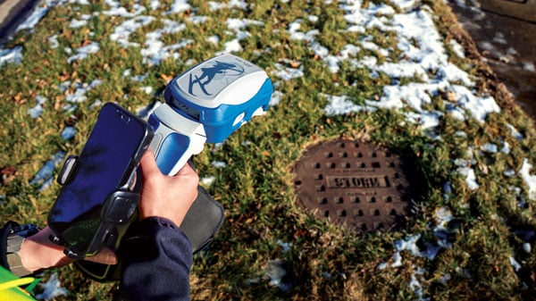
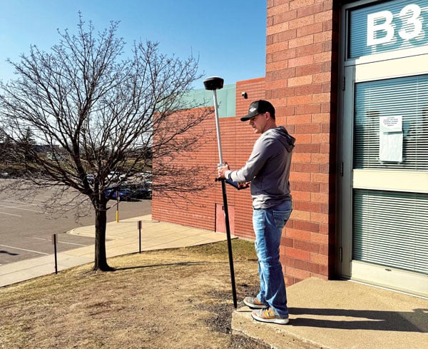
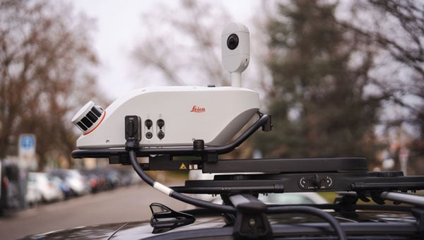
Anyone who has had to carry cumbersome legacy surveying instruments over rough terrain can probably confess to daydreaming about having something like Mr. Spock’s “Tricorder,” a small device that captures everything about your surroundings. Such sci-fi devices anticipated the “reality capture” wave of the present day.
Multi-sensor stacks have become the norm and are essential for many geospatial applications. Consider vehicular autonomy. For safety-of-life considerations, no single positioning technique could suffice. Each sensor type has strengths and weaknesses. Lidar has good behaviors under certain conditions: radar, GNSS and inertial measurement unit. That is why a typical autonomy stack will include one or more sensor types. More data of different types is better, especially if it can share a common, highly precise spatial reference. Surveying and mapping are benefiting laterally from the research and development for autonomous solutions. In some ways, autonomy solutions have benefited from the long-standing legacy of research and development in geomatics applications.
Platforms, Positioning and Progress
As surveying and mapping practitioners, we are bombarded with news and ads for a seemingly endless parade of the latest reality capture devices: handheld SLAM scanners, drone payloads, mobile mapping systems, backpacks and more. Many are using OEM sensors from a relatively small subset of manufacturers; this trend is similar to the wave of third-party GNSS rovers a decade ago.
While the individual sensors deliver astounding data, integration into field capture devices often shortchanges one crucial element: positioning. There is a tendency to keep cost, size, and power consumption low by including positioning components (e.g., GNSS and IMU) originally developed for mass-market applications like vehicle autonomy. Not every handheld SLAM system can afford to add survey-grade capabilities, like that delivered by dedicated surveying rovers costing tens of thousands of dollars, so users need to have realistic expectations.
A surveyor might wince when they hear a marketing claim from yet another SLAM device manufacturer claiming, “centimeter precision, anywhere!” Even with top-tier survey rovers, skill and experience temper such expectations. But what if the platform of a highly capable, survey-grade rover, packed multiple data capture sensors? This idea is not new, and the evolution of rover-based solutions in many ways, enabled the development of the current wave of reality capture systems.
Positional Integrity Through Motion
It is a prospect that might seem counter-intuitive: deriving a precise position while moving the instrument. Providing tilt compensation for a GNSS survey rover (on a pole/rod) had long been desired. The impetus was to improve efficiency, namely by removing the time spent leveling the rod for each observation. Freeing the user from the tyranny of the bubble was one goal, but it was also the first crucial step in being able to enable further sensor integrations.
Integrity through motion is one of the foundational elements of GPS/GNSS: the trajectories of the navigation satellites can be predicted with high confidence. For example, frequently updated ultra-rapid orbit products utilized in many GNSS solutions rival the “precise” orbit products we used to wait days for. Similar principles apply to modern tilt compensation solutions. The movement of a rover head provides a highly predictable reference trajectory for the orientation of the tilt sensors.
Electronic bubbles and tilt compensation have been around for many years. For example, compensators are standard in many instruments, such as total stations, and tightly coupled GNSS+IMUs in mobile systems for road, sea, and airborne mapping. Consider the SPAN system from Hexagon | NovAtel. Such systems compute centimeter-grade positions for moving cameras, lidar units, and other sensors, while taking into account heading, speed, pitch, yaw, roll, and in the case of marine systems, heave — at highway speeds, plowing through rough seas, or zipping across the sky. The challenge, though, was miniaturization. Could such capabilities be developed to fit into a standard survey rover?
Tilt compensation in rovers began to appear over a decade ago. For example, in some JAVAD rovers of the day; other manufacturers were soon to follow. These were at the time, unfortunately, magnetic-oriented systems. While a noteworthy achievement, the inconsistencies inherent to magnetic reference and cumbersome calibration routines soured a lot of users to the idea of tilt compensation.
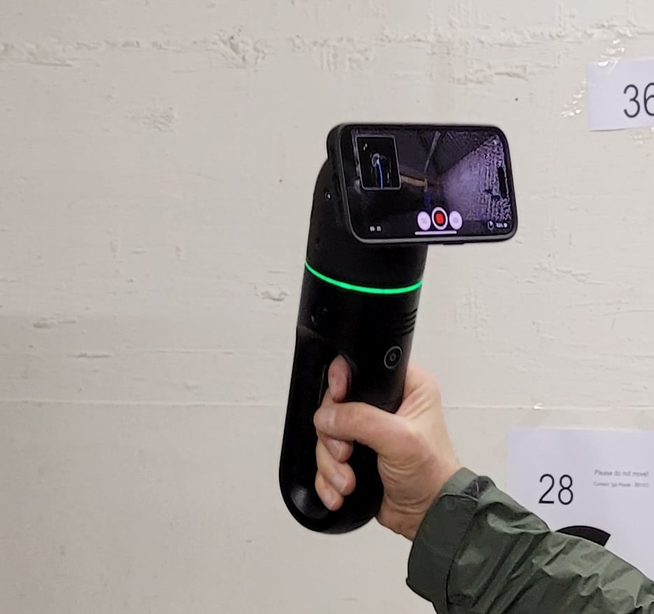
The Leica GS18T marked the beginning of the multi-sensor stack trend for GNSS rovers, introducing no-calibration tilt compensation in 2017. This was soon followed by the GS18I, adding a camera for offset points, stakeout, and point cloud creation. Since then, such features are common across the industry. (Photo: Gavin Schrock)
This changed with the announcement by Leica Geosystems at the October 2017 INTERGEO international exhibition and conference in Berlin of the no-calibration tilt-compensated Leica GS18 T GNSS rover. This was one of the first “stacked rovers,” spawning a chain reaction of similar feature integration across the industry.
“The main thing we wanted to do was to make measurements faster for the user,” said Bernhard Richter, vice president of product management geomatics at Leica Geosystems, when I interviewed him at the time of the GS18 T launch. The process was part of a 10-year initiative to improve field efficiency, but it was not the sole goal. Dynamic precise positioning was the first step to enabling the integration of additional features.
After a year or so of end users getting over the skepticism of tilt compensation, you will now find it as a standard feature on nearly all new GNSS rovers. Of course, users need to verify and build confidence in new solutions. Surveyors of a certain age might remember when nervous party chiefs would require taping/chaining of distances to verify if those “new lasers” were working right.
Adding Sensors
GNSS in sky-view-challenged environments was the impetus for the first multi-sensor integrations. Namely, how to get the shot under the adjacent canopy, or roof overhang. While manufacturers and integrators had been offering various ranging lasers as peripherals GNSS rovers since the late 1990s, the Achilles heel was the orientation; limited to magnetic references. Despite this handicap, such offset point solutions were popular for certain applications (e.g., asset inventory, trail mapping).
Once dynamic precise positioning was achievable in a rover head, it could become a platform for additional data capture sensors. Cameras were the logical first step. A camera included on some JAVAD rovers was leveraged by some users for photogrammetric computation of offset points. Leica Geosystems soon followed up its GS18 T, with the GS18 I, which added camera-based offset point capabilities. Rather than some early photogrammetric offset point solutions where you took individual static photos, with the GS18 I, you capture a series of precisely spatially registered images while in motion. In the companion Leica Captivate software, you can quickly identify the offset points. The same images can be processed in the software as a 3D point cloud, which many users do.
Again, we started to see camera-based offset point (and stakeout) solutions in nearly every brand of GNSS rover. What’s next? We’re starting to see lidar added to some rovers. But at what point should a field user reach for a dedicated reality capture device, rather than trying to do everything with an enhanced GNSS rover? There’s a lot to consider, so we asked some integrators for insights.
Eric Gakstatter, principal and owner of Discovery Management Group, has been promoting multi-sensor at conferences for decades. His firm also has developed and consulted on such sensors in conjunction with various manufacturers. Gakstatter highlighted some successful sensor integrations.
“There’s a difference between, say, those lidar SLAM devices and rovers,” he said. “With one, you are looking for a point cloud, but with the other, you are more interested in discrete points of interest; you’re very deliberate in measuring specific features.” Gakstatter had recently given me an overview of the Eos Positioning Systems Skadi GNSS rover, a next-generation receiver from the makers of the Arrow GNSS receiver systems. The Skadi features a built-in antenna and full tilt compensation, but also can be paired with a companion smart handle that offers some interesting multi-sensor capabilities. First, there is a “virtual pole” feature that wirelessly measures the distance straight down to the ground, eliminating the pole for certain applications. Another feature is a ranging sensor with a visible laser pointer for offset points and stakeout. “You can pull the trigger and trace along a curb line, collecting points in a continuous mode,” said Gakstatter. “It’s literally point and shoot simplicity.”
The Eos Positioning Systems Skadi rover fits on a pole, or this handle with automated height-above-ground and offset features measurement sensors. (Photo: Eric Gakstatter)
His firm has also developed, in partnership with another manufacturer, an angle encoding peripheral that mounts on the pole. When used in conjunction with a rangefinder-style laser, the GNSS rover can perform traverses in much the same manner as a surveyor’s total station. In a field demonstration for a utility services company, the crew did such a traverse along a roadway, then under canopy, in the shadow of tall buildings, inside a covered parking garage, and then closing back on the beginning outdoor points. This process would have taken much longer with conventional instruments.
While a strong advocate for multi-sensor integration, Gakstatter points out some of the challenges. “It just takes so long to get the right technology, the right packaging, the right power consumption, and then the manufacturers might need years to incorporate it,” said Gakstatter. “You can talk about these future technologies, but it just takes so long. Think about it, why haven’t the iPhone or the iPads become more rugged? Why can’t they make a replaceable battery? You know, all kinds of technology could be done in consumer devices, even multi-frequency GNSS, but they don’t do it. It’s driven by power consumption, real estate inside, size and cost.”
Adding peripherals is another approach for multi-sensor rovers. This system enables sky-view challenge data collection, as in this location between two buildings, with an angle encoder (middle of the pole) and offset rangefinder (under the Eos Skadi rover). With this combination, users can perform the equivalent of closed traverse loops. (Photo: Eric Gakstatter)
“I think you’ll find that some folks who just are going to go after the low-end sort of basic RTK receiver and some simple integration,” said Gakstatter. “But, you’ll always have the manufacturers that are sinking a lot of time and money into research and development, the pioneering stuff. But it is very expensive and for a relatively small market.” When new solutions are developed and integrated by those willing to invest in research and development, users gripe about high prices for the gear, but the payoff is a major increase in productivity and safety. Sure, such features might show up in lower-price-range rovers, but with varying degrees of performance.
Rover Lidar
Lidar can be quite powerful for creating 3D point clouds and models. However, doing a formal scanning campaign with a large-format laser scanner is not always justified. Even if a site is scanned, surveyors might still need to shoot key features with a total station and/or GNSS rover. This practical reality is why limited scanning capabilities (and imaging) were integrated into some total stations. For example, Trimble SX12 total station and the Leica Nova MS60 Multistations. As such instruments provide, by default, highly precise spatial references, any of the selective scans are automatically registered. Users find this aspect highly attractive, capturing rich 3D point cloud data, and images, without the need for extra registration steps.
It was inevitable that GNSS rover manufacturers eventually would seek to add lidar scanners. In what might be one of the first, if not the first such integration (in broadly distributed commercial rover), CHC Navigation (CHCNAV) has its RS10 rover. It is a fully functioning high-performance GNSS rover but with a puck-style scanning head (16 channels or 32 channels for 320K or 640K pulses per second) mounted vertically, offset under the antenna. RTK and PPK workflows are supported.
It can operate as a rover or as a SLAM scanner. It should be noted that the scanner head is of the same quality as similar OEM heads on many SLAM handhelds, small mobile mapping systems, and even drone payloads.
According to Logan Zhou, mobile mapping business director at CHCNAV, when the RS10 was released in 2024, it brought a substantial boost to its mobile 3D sales. I asked what the fundamental differences were between this enhanced rover and a conventional SLAM mapping instrument.
“Compared to a traditional SLAM solution, we have integrated a high-performance receiver and antenna,” said Zhou. “So, the users can acquire the results with geographic coordinates directly.” He added that there are three cameras integrated into the RS10, for image capture and point cloud colorization. There are elements of visual and lidar position stabilization, that are also leveraged in what they call SFIX, to extend positioning capabilities into GNSS challenged areas.
Matt Sibole, PLS, owner of iGage Mid-Atlantic, part of the popular iGage surveying equipment sales and support network, has several RS10s in his rental inventory. He finds the unit very capable as a reality capture system. Sibole also related that his customers are also very pleased with the CHC units that have camera-based offset and stakeout capabilities, like the i89 and i93 (that have forward and downward tilted cameras for stakeout). The i89 and i93 point cloud capabilities utilizing photogrammetry are also quite intriguing to many of his customers.
One consideration of adding a high-precision SLAM scanner to a rover is weight. When using one for standard rover point capture for extended periods, the added weight can become a burden. Sibole prefers a different topography survey workflow. “I’ll go through with my CHC i89 rover, and pick specific points I need, as a check,” said Sibole. “I’ll shoot center and rims of manholes, shoot some property corners, etc. Then, I put that away and grab the RS10. With a connection source from my base, and I set it up for NTRIP, I can just walk around the site and collect the lidar.”
We discussed the growing trend for reality capture systems to have multiple deployment configuration options. You will see some compact systems that can be handheld, mounted on chest or backpack harnesses, attached to vehicles, and even carried as drone payloads. The one element that does, unfortunately, sometimes gets shortchanged is the GNSS component. As I alluded to earlier, there are low-cost GNSS boards that might be suitable for coarse mapping applications, but if you are looking for engineering design or construction quality models, quality makes a big difference.
Cameras Abound
Cameras are relatively small, light and low-cost. They have been a logical integration for at least some models of nearly all GNSS rover brands. Nearly a decade ago at an INTERGEO exhibition, I spoke with Winston Wen, CEO of the then relatively new brand of Tersus GNSS. Wen predicted a great future for multi-sensor GNSS rovers, noting that no-calibration tilt would be the crucial first step, which Tersus would integrate into their line of rovers.
A GNSS+IMU+Camera integration: the Tersus Trek, here shown being used on a survey for a school expansion project. (Photo: Dustin Harr, Desert Creative group)
Next, he wanted to develop enhanced rovers for users who could benefit from not having to pack a bunch of different instruments into the field, especially in remote areas, like for his customers in the Australian outback. Terus now has Trek, essentially a version of their flagship high-performance Oscar rover, but with an integrated camera.
“I think photogrammetry could overtake lidar, for many applications, as the sensor fusion gets better, the algorithms get better, and the actual physical hardware gets better,” said Jesse Huff, surveyor, geospatial thought leader, and general manager of Tersus in North America. “Even in the literary world, you know, a picture is worth a thousand words. There’s a lot more information to be gleaned from the images and the stuff that we’re doing with point clouds. The feature recognition revolution is just getting started.
“The point cloud that we’re getting out, I won’t say it’s as clean as some lidar data,” said Huff. “There’s a little bit of noise in that, but it rivals lidar data for most of what folks are doing, save for structural mechanical work.” The camera-based offset point and stakeout workflows of different manufacturers vary. Tersus offers the users three approaches. One is to initiate the automated image capture sequence by picking a target object in the controller, then it will proceed to look for the same point in subsequent images, to perform the triangulation.
The Tersus Trek enables two types of camera-based offset point measurement. The images also can be processed into point clouds for feature modeling and measurement, as shown in this example from a survey for a school expansion project. (Photo: Dustin Harr, Desert Creative Group)
Another is to take the image sequence and pick points in two or more images in the controller. Huff joked that the old-school surveyor in him prefers the latter option, but notes that a feature recognition algorithms improve, the process in such systems will become even more automated. One more option is to create a point cloud from the images and then select points from that.
One characteristic of legacy close-range photogrammetry, that is the source of lingering doubts about its utility, is the cumbersome processing workflows (of the past). Huff pointed out that the creation of the point clouds from the Trek is performed on the data controller, like their TC40. The same Tersus field software can run on an Android tablet or phone.
“I’ve done point cloud generation with Tersus Nuwa field software using my phone,” said Huff.” I’ve got a Samsung Z Fold5; it’s got a better processor, a quad-core processor, than the first computer that I was using for point cloud registration and processing.
That brings up a good point, noted Huff: “When you talk about sensor stacks, it’s not just sensors, it’s technology stacks. It’s not just taking advantage of the tech that’s in the receiver, it’s also taking advantage of the tech that has evolved in terms of mobile computing devices, artificial intelligence (AI), the cloud and more.”
GNSS Quality
For many indoor, GNSS-denied environments, there are reality capture systems that can produce, through visual and SLAM stabilization, highly precise 3D point clouds and downstream models. A good example is the BLK family of reality capture devices from Leica Geosystems. The Leica BLK2GO is a handheld SLAM device that scans up to 420,000 points per second. It employs a tight integration of an internal IMU, a unique camera-based progressive spatial reference technique, and SLAM stabilization (together dubbed “GrandSLAM”).
For indoor applications, the crucial reference is relative to the structure. Outdoors, a SLAM scanner would typically need terrestrial reference points for absolute spatial registration, and/or leverage GNSS. Here is where the quality of the GNSS could mean the difference between having to set many control points with other instruments (substantially adding to project costs), or an appropriate minimum.
For their handheld, camera-based 3D mapping system, Looq AI opted for a high-precision GNSS board from Septentrio to integrate with an IMU for their automated PPK and AI processed workflow. (Photo: Gavin Schrock)
This paradigm was of prime consideration for Looq AI, when they were developing their flagship handheld, camera-based reality capture system. The system is a harbinger of another trend (that would need a separate article), about how close-range photogrammetry is coming into its own, and with recent advancements and techniques, is becoming a serious challenge to lidar, and especially SLAM lidar. I compared point clouds for a small site, between that of the Looq handheld, and a large format terrestrial laser scanner — and could not see any difference. How does it do this? And what role did precise GNSS play in this?
The script has been somewhat flipped. In the case of one recent development, instead of adding cameras to a rover, high-quality GNSS+IMU was added to high-quality and rigorously calibrated camera-based reality capture handheld.
“From a technological foundation, we knew that for triangulating thousands of image features, which are represented by points in the real world, multiple optics were required,” said Dominique Meyer, co-founder and CEO of Looq AI. “We create a triangulation algorithm for the camera system that would provide robustness that is much greater than many of the photogrammetric single-camera solutions out there, and at the same time, exceed the point cloud density of many lidar point clouds. A precise spatial and temporal component is crucial to apply to the observations.
“If you look at computer vision and GNSS independently as two independent sensor stacks, GNSS is robust in very specific environments,” Meyer added. “You have the number of satellite observations, quality of observations, precise time, and a set of corrections. Only when those are all good do you have great GNSS localization capability. The second you lose any of that, because you’re in a forest or under a roof or a bridge, you don’t necessarily know how robust your GNSS localization is.”
This is why Looq decided to make post-processed kinematic (PPK) an integral part of their workflow; PPK is performed automatically for the user, in the cloud, before point cloud processing. “Fundamentally, we knew that post-processing would apply better corrections, because it enables a backward pass in the corrections, fundamentally always exceeding or equating the quality from an RTK solution,” said Meyer. “Because our computer vision algorithms always run after the capture, we knew we could afford to run a PPK service, which would also allow us after the fact to decide which correction services to use. If you have a local base, you can use that. If you don’t have a local base, you can use a public correction service. And if you don’t have that, you can use a PPP solution.”
Another key component was the choice of the GNSS and IMU components of the Looq handheld. “We considered many hardware options. We had a layout of pretty much every GNSS receiver at the time out there. What we cared about was multiple bands, especially the newer bands like L5,” said Meyer. As noted, there are GNSS boards for many different applications, and while some of the lower-cost solutions are “multi-constellation,” they may only support a limited number of signals per constellation. Being able to work in limited sky and high multipath environments was important; low-cost boards can struggle with this.
Looq chose components from Septentrio. “The other part is spoofing and interference,” said Meyer. “Not that it is super common, Septentrio has put a lot of effort into filtering to make sure that you don’t get third-party interference across the RF spectrum that would affect the quality of the GNSS. Tests we had completed demonstrated that with the multiple bands and with the RF reliability, it was the best, which would allow us to produce the best market product.”
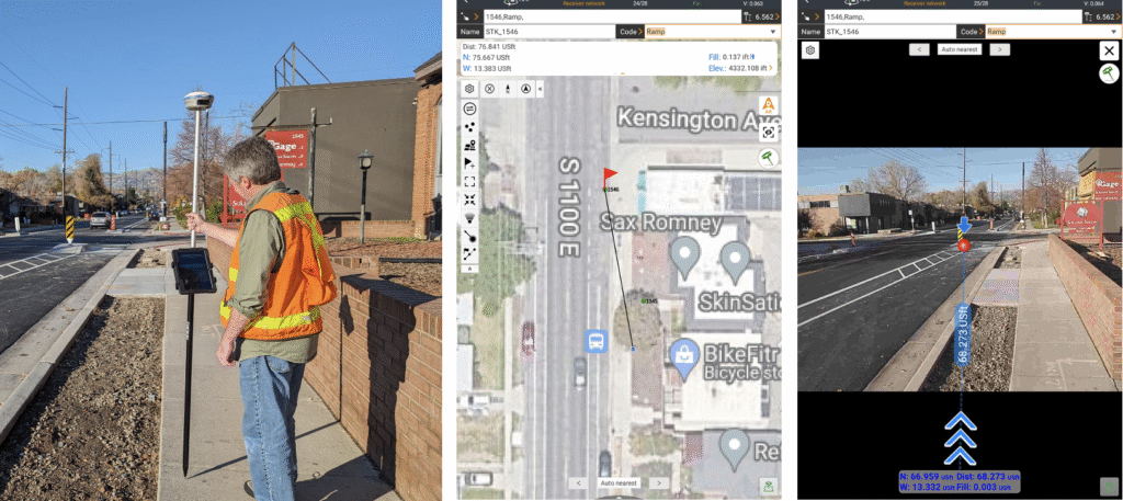
Visual offset point and stakeout with the CHC i89 rover (left), and in the Landstar field software (center and right). (Photo: J. ZoBell, iGage)
Duality
I circled back with Bernhard Richter of Leica Geosystems, who shepherded the development of that pioneering stacked rover, the GS18 T. We discussed the question of GNSS rovers as a multi-sensor platform. Several key themes emerged from the conversation.
Surveying is, in many ways, reality capture, but it is handled in a different, more selective and focused manner. Features observed must often meet very tight precision and integrity expectations: property marks, control for engineering and construction, monitoring, and more. Reality capture is about mass data capture. While there are advantages for certain applications in the proximal richness of mass data capture, there always may be the need for discrete points.
“When we designed the GS18 T, we recognized a challenge in bridging the gap between single-point measurement and reality capture,” said Richter. “Our goal was to improve the efficiency of discrete point collection while maintaining survey level quality.” With tilt achieved, the later addition of camera-based offset point capabilities to the GS18 I, was simply to improve efficiency even further.
“One of the main concepts behind the GS18 I is that everything you capture through photogrammetry is immediately aligned with the same reference frame or coordinate system as your normal GNSS points,” said Richter. “This additional feature does not put any extra burden on your hardware, and if you work in the conventional way, it performs just as well as any other method.” While you can produce point clouds from the images, that was not the primary goal, but a nice feature for certain situations. This raised another consideration: is capturing potential excess data a wise move?
“You can use mobile scanners, or sensors on your rovers, and generate point clouds of everything,” said Richter. “Capturing massive amounts of data is easy from a hardware perspective. But then you have to process and use all of this data. Right now, the software side of the industry is playing catch up. There just isn’t enough automation yet, though AI will certainly help with that moving forward.” It is a common complaint in the geospatial sector that there are substantial backlogs in the office processing of reality capture data.
“Yes, you can scan everything and then have someone extract the needed data from the point cloud,” said Richter. “But depending on the application, your client might be better off with a more conventional survey of discrete points chosen in the field. That said, for capturing large areas or long road corridors, a terrestrial scanner, mobile mapping system, or drone may be the most efficient option.”
Those applications aside, I hear misgivings among surveyors about the “scan everything” approach. They often can meet the needs of clients with conventional topo, mapping right there in the field, and that reduces the office component dramatically compared to a scanning workflow. So, is there a compelling need (for now) to add mass data capture sensors to survey rovers? Perhaps not. As prices for reality capture devices, SLAM scanners, drones, etc., drop over time, they become part of a firm’s standard kit, along with a rover and total station.
“We’ve always been keenly aware of the technology hype cycle,” said Richter. “There’s the initial excitement, then a trough of disillusionment, but if a solution truly improves productivity, adoption comes later. We could have added magnetic oriented tilt compensation long ago, but recognized that we could not rely on the Earth’s inconsistent magnetic field. It could have resulted in a substandard product. It was best to invest our efforts into the type of tilt used in the GS18 T.” While I did not press for any details about what might be next for their research and development, I sensed that the subject of additional sensors for rovers would keep the same principal in mind.
“At the end of the day, you need to solve specific customer problems,” said Richter. “There’s a lot that can be done, but not everything adds efficiency in the way people might expect. Often, the downstream automation isn’t there yet to handle a flood of additional data. Integrating additional sensors can require tradeoffs, and in many cases, there may already be more efficient options available. Not every application benefits from a mass data capture approach.”
What If?
Manufacturers can be averse to revealing what they’re working on next but watching lateral developments in the world of geospatial sensors, certain moves might seem inevitable. We’ve seen how disruptive the addition of various types of Time-of-Flight (ToF) sensors, to consumer tablets and phones, has been. For certain (very short-range) applications, the point cloud quality from some phone sensors rivals, or even bests that of some lidar systems. There are also examples of highly refined ToF sensor implementations in reality capture devices, such as the Leica BLK2GO PULSE.
Approaches to adding multiple sensors, be that to GNSS rovers, or dedicated reality capture devices, may someday merge as newer, smaller, and more capable sensors are added to the former, and improved positioning capabilities are added to the latter. The Leica BLK2GO PULSE is an example of where solid-state time-of-flight sensors can be leveraged, rather than traditional laser scanning profilers (that have moving parts). (Photo: Gavin Schrock)
There has even been a wave of devices that allow you to attach your ToF-enabled phone to the handle, which also features an RTK-capable GNSS antenna and receiver. These have become popular, for instance, capturing utilities in an open trench before they are buried. One concern is that there is a tendency to skimp on the GNSS hardware. You only get to measure those pipes once. Why not get the best-quality data?
So, why not put the ToF sensors on a high-performance rover? Someone is bound to do it; it is just a matter of time. The same applies to other solid-state lidars. There are some types of what folks call solid-state lidar that have moving parts on the MEMS. But now we are seeing true solid-state lidar (no moving parts), for instance, that are integrated into mobile mapping and road inspection systems by XenomatiX. There are still some miniaturization and power budget issues ahead, but we will likely see solid-state lidar on rovers at some point, which would overcome the weight handicap of SLAM lidar heads attached to rovers.
Then we can look ahead to the near-sci-fi realm of quantum sensors. Read more on this subject at: gogeomatics.ca/quantum-surveying. Quantum technologies could someday upend imaging and lidar approaches, and other sensor types. For example, quantum radar could employ more bands on a single, smaller antenna than the large separate antennas required of conventional radars. Radar has particular advantages for foliage penetration. Imagine scanning a roadside with solid-state lidar, and then radar enhances what you can see under and behind the vegetation.
Relatively small quantum antennas have been demonstrated to detect the entire RF spectrum; these could be super-sensitive to specific bands and help mitigate multipath, spoofing and jamming hazards. On the subject of commonly mentioned vulnerabilities to GNSS, quantum magnetometry is showing promise for not only an alternate navigation approach but could act as a “canary in a coal mine” for GNSS applications, detecting offsets that would indicate spoofing.
Within the last month, a functioning and commercially offered quantum navigation device was announced, and it is nearly pocket-sized. Sorry for the geek detour, but there could be fascinating things ahead.
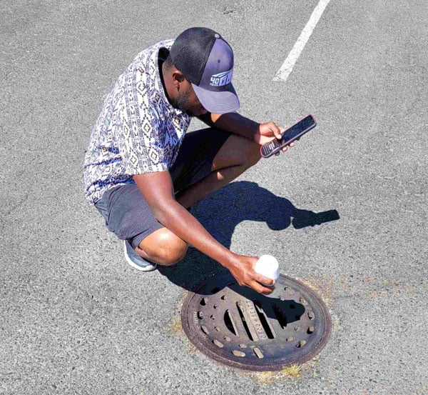
The compact ComNav Technology Venus rover has tilt compensation and a ranging/tracking laser that can be used to do measure-ups when on a pole or offset point/stakeout as shown in this example of measuring a drainage hole invert. (Photo: Gavin Schrock)
Some folks dismiss the prospect of a multi-sensor GNSS rover as being like a multi-tool, like a Leatherman or Swiss-style military knife. Super handy when you need it, but the individual tools might not ever match the utility of a dedicated tool. I’m among those who, to some degree, disagree with that analogy. Unless it is a case of some slapped together systems (with the lowest cost components possible), for many systems, the added-on features can boost productivity and deliver precise data (with careful and appropriate practices).
Sometimes, the zeal to stack rovers is not always successful. There was the case of a manufacturer embarking on an earnest initiative to build a sensor-rich add-on for a GNSS rover, which some envisioned as a way to match the capabilities of a total station. However, it appears that the initiative has been suspended.
There’s a lot for users to consider: do they invest in multiple dedicated instruments, and can they afford the best of each? But on the other hand, is the stacking of multiple sensors on a GNSS rover really warranted or even practical? Can combo systems effectively meet most of your needs? Do you consider fit-for-purpose solutions? The good news is that the progression of innovation in hardware and software is continuous. There are a lot of intriguing options already out there, with more to come.
VIAVI Solutions Inc. has introduced its second-generation RSR Transcoder, engineered to maintain operational capability in GPS/GNSS-denied, degraded or disrupted space operational environments.
This development comes amid a global increase in GPS and GNSS jamming and spoofing, which have become standard tactics in electronic warfare. These hostile activities, while primarily aimed at military operations, also threaten sectors that depend on precise timing and geolocation, such as aviation, communications and emergency services.
The new RSR Transcoder is designed to deliver assured positioning, navigation and timing (PNT) in a wide range of outputs to upgrade legacy systems. The device features a GPS full constellation simulator and employs a patented algorithm to rapidly convert assured inputs — including M-Code, SAASM, IMU/INS, and other signals of opportunity — into universal GPS L1 and L2 signals with both C/A-code and P-code outputs. This capability allows for the straightforward enhancement of older GPS systems, providing them with modern, resilient PNT functionality.
The RSR Transcoder is housed in ruggedized IP68 enclosures suitable for deployment on land, sea and air platforms. It is capable of covert, lights-out operation and offers a 100 Hz output rate with an ICD-GPS-153 interface. The device is available with holdover oscillator options of 4, 8 and 24 hours, supporting continued operation during signal loss.
On Display at the Joint Navigation Conference
The RSR Transcoder will be demonstrated at the 2025 Joint Navigation Conference, which is held June 2-5 in the Greater Cincinnati Area and jointly hosted by the Departments of Defense and Homeland Security. It will be on display at VIAVI’s booth #406. VIAVI’s Inertial Labs division will also demonstrate recent breakthroughs in D3SOE navigation at booth #430.
VIAVI and its Inertial Labs division will also give three presentations:
“3D Vision-Based Positioning for Autonomous Aerial Platform Navigation and Human-in-the-Loop Reconnaissance Mission”: Monday, June 2 at 1:50 PM ET
“Anti-Jam/Spoof Phased Array Antenna”: Wednesday, June 4 at 10:50 AM ET
“Retrofitting At-Risk GPS Defense Equipment with a Multi-Orbit LEO and GEO Clock System for Resilient PNT Services”: Wednesday, June 4 at 11:30 AM ET
oneNav has developed an L5-direct GNSS receiver ASIC, a breakthrough that enables devices to directly acquire and track L5-band satellite signals without relying on the older, more vulnerable L1 signals. The L5-direct receiver was rapidly designed and brought to market using the GlobalFoundries 22-nanometer FDX platform, which offers advanced mixed-signal integration and ultra-low power performance for both radio frequency and digital functions.
The new receiver features a unique processor architecture, described as a “GPU for GNSS,” that eliminates dependence on L1 signals. This approach is designed to address critical vulnerabilities in aviation, defense and consumer navigation applications, where L1 signals are increasingly susceptible to jamming and spoofing. According to oneNav, the L5-direct technology is completely immune to L1 jamming and offers six to seven times greater resilience to interference and jamming in the L5 band compared to legacy solutions. It also delivers a tenfold improvement in measurement precision, faster initial location acquisition, enhanced accuracy in dense urban environments and reduced power consumption compared to L1-dependent receivers.
L5-direct can be deployed across defense, national security, industrial and consumer markets, offering a significant boost in jamming resistance for GPS-based positioning and timing applications.
“The need for ultra-low power consumption with high jamming resilience is acute in the rapidly growing unmanned vehicle segment, including drones,” said oneNav CEO Steve Poizner.
Earlier this year, oneNav partnered with three military agencies to evaluate L5-direct in terrestrial, maritime and aerial environments under simulated electronic warfare conditions. The trials confirmed the technology’s immunity to L1 interference and demonstrated its superior resilience to L5 jamming.
Key features of the GlobalFoundries 22FDX+ platform that enabled this innovation include optimized power-performance balance, advanced mixed-signal integration, ultra-low power consumption and enhanced RF performance, supporting a wide range of applications.
The L5-direct technology is now available as licensable intellectual property and can be customized for use in a range of applications, from consumer wearables to unmanned aerial vehicles. It can also complement military-grade M-Code solutions for applications requiring high resilience, low power and rapid signal acquisition.
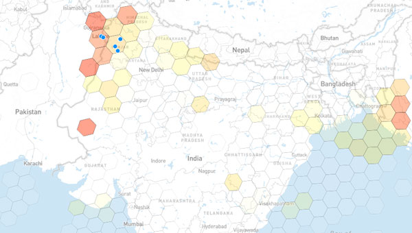
India continues to make significant progress in developing indigenous unmanned aerial vehicles, loitering munitions and autonomous systems. However, many of these platforms face a critical vulnerability: their reliance on unprotected satellite navigation. This threat is no longer theoretical.
Recent escalations with Pakistan, including drone incursions, cyber operations and suspected GPS interference near sensitive border areas, have underscored the growing use of low-cost, easily concealed GNSS jamming tools. Such devices can disrupt UAV operations, sever navigation links and compromise mission success, regardless of how sophisticated the system may be.
Without robust GNSS protection, even the most advanced unmanned systems are at risk of operational failure, loss of control and diminished national security capabilities.
One countermeasure comes from infiniDome, a global provider of GNSS protection technology. The company develops lightweight, easily integrable anti-jamming solutions that are already deployed by leading defense forces to ensure continuous operation in contested electromagnetic environments.
InfiniDome has extensive operational experience in active conflict zones and a strategic focus on compact, cost-effective systems. These solutions are well suited to India’s growing demand for scalable, lightweight UAVs and autonomous platforms, according to the company.
“Seen & Heard” is a monthly feature of GPS World magazine, traveling the world to capture interesting and unusual news stories involving the GNSS/PNT industry.
Free navigation history course
Photo: Harvard University
Harvard University offers PredictionX: Lost Without Longitude, a free online course that examines the evolution of navigation from ancient methods to modern technologies. The program explores the science and history of navigation, focusing on the challenges of determining longitude before GPS existed. It highlights key advancements, such as John Harrison’s marine chronometer and the Longitude Prize. Through multimedia content — including videos, infographics and Worldwide Telescope tours — the course is designed to demonstrate how centuries of advancement in navigation enabled humanity to achieve milestones such as landing on the moon.
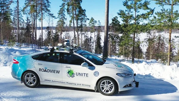
Self-driving cars collect geospatial data
Photo: Finnish Geospatial Research Institute
In Finland, self-driving cars are being used to collect geospatial data to address urban challenges. The ARVO autonomous vehicle from the Finnish Geospatial Research Institute is equipped with high-precision sensors that map its environment in real-time, collecting information on road conditions, urban vegetation as carbon sinks and factors influencing flood risks. In partnership with Aalto University and funded by the European Regional Development Fund, this initiative seeks to explore various uses of this data, such as city planning, environmental monitoring and infrastructure management.
Stopping scammers
Photo: Carlos Alvarez / iStock Editorial / Getty Images Plus / Getty Image
Google has taken legal action against a network of scammers responsible for creating more than 10,000 fake business listings on Google Maps. The scammers fabricated profiles targeting urgent service industries and bolstered them with fake reviews to appear credible. Victims were misled into contacting these fake businesses, which then sold their personal information as “leads” to legitimate service providers without consent. Google has removed the fake listings and is suing individuals involved in the scheme, CBS News reported.
Mapping Uganda’s disappearing tropical glaciers
Photo: guenterguni / E+ / Getty Image
Project Pressure, in collaboration with UNESCO and the Uganda Wildlife Authority, conducted an expedition to the Rwenzori Mountains to map the region’s disappearing tropical glaciers. The team created the first 3D model of Mt. Stanley’s glaciers and installed monitoring equipment, revealing that Mt. Speke and Mt. Baker have lost their glaciers entirely, while the Stanley Plateau Glacier has shrunk by 29.5 percent since 2020 and is heavily fragmented. The project aims to continue monitoring the glacial retreat, develop mitigation strategies and engage the local community in ongoing research.
In today’s hyper-connected world, GNSS signals face unprecedented threats from jamming and spoofing attacks. As these signals traverse 20,000 km from satellites to Earth, they become vulnerable to interference that can degrade positioning accuracy or eliminate position availability altogether. Understanding how to recognize these attacks and implement protective measures has become critical for industries depending on precise positioning.
Two Distinct Threats
Jamming occurs when signals are disrupted or denied, making it difficult or impossible for receivers to interpret information correctly. In contrast, spoofing involves malicious transmission of fake signals that mimic real ones, tricking receivers into delivering inaccurate location data. Spoofing is basically someone trying to pretend they’re a real satellite.
While jamming focuses on disruption through noise and interference, spoofing relies on deception, sending false signals that systems accept as legitimate. Both pose serious challenges, but their differences require unique detection and prevention strategies.
When jamming occurs — whether it be noise (chirp) jamming, tone jamming or pulsed jamming, devices may experience significant signal degradation resulting in interrupted communication and loss of both data and situational awareness. By contrast, spoofing — be it meaconing, coherent or signal overlay — can subtly alter data, leading to false readings and misguided actions.
How to Know If Your Signal is Under Attack
With the surge in electronic devices in today’s IoT-rich world, interference from radio frequencies — whether intentional or situational — is common. This is partly because multiple sensors are often situated close to each other on equipment, vehicles, drones and more. So how do you know if your system is under attack? GNSS interference typically manifests through several telltale indicators, including erratic or unstable device performance, frequent signal interruptions or a marked decline in data precision. Deception often reveals itself via red flags such as unusual location data inconsistencies, abrupt and unexplained shifts in data patterns, signal quality degradation (e.g., drop in carrier-to-noise ratio or high noise floor), sudden position drifts, frequent re-acquiring of signals, large discrepancies detected by Kalman filters or unexpected signal peaks.
With jamming, the first step is to recognize you’re being jammed by using a receiver as a jamming detector and utilize an onboard spectrum analyzer to identify interfering frequencies. Not only is this valuable for external jamming, but it is hugely helpful for companies as many accidentally self-jam with other components on the device.
Identifying these signs promptly is crucial for preserving system functionality and preventing potentially catastrophic consequences.
Industry Impact: Beyond Navigation
Beyond the military and cybersecurity, public safety, transportation, marine, construction, agriculture and utilities are highly susceptible, posing a significant threat.
Autonomous vehicle systems face the greatest risk, as they depend heavily on GNSS data for navigation accuracy and split-second decisions. Jamming can cause vehicles to struggle with lane-keeping, misinterpret traffic signals, or stop without warning, while spoofing presents a more subtle, yet still dangerous threat by potentially diverting vehicles from intended routes with harmful intentions, increasing the likelihood of collisions with obstacles, other vehicles or people.
Interruptions in key transportation networks can also lead to vehicles being misdirected, potentially leading to collisions, and even becoming targets for malicious actions like cargo theft. Railway systems have emerged as major targets, with “ransomware attacks becoming the most prominent threat against the rail sector” across the EU, according to Marianthi Theocharidou of the European Union Agency for Cybersecurity (ENISA). In the Baltic region alone, 46,000 aircraft exhibited possible jamming signs between August 2023 and March 2024.
In ag, precision farming technologies requiring reliable data for optimizing planting, watering and harvesting schedules face major disruptions that translate directly into resource waste and profit drain.
Navigation systems critical for safety and cargo protection are particularly vulnerable in maritime and logistics. Recent incidents include the hijacking of trucks carrying over $1 million worth of Santo tequila in Texas, where investigations suspect spoofing made the vehicles appear in the right location when they weren’t.
The Growing Accessibility of Attacks
Where skilled hackers once dominated the scene, inexpensive jammers now flood the market. Despite being illegal in most countries, these devices — often disguised as USB sticks or car chargers — have become increasingly accessible. One tiny 10mW chirp jammer plugged into a car socket can knock out GNSS signals within several miles.
Spoofing, once a complex task, is now achievable using open-source software or low-cost components, making robust countermeasures essential for systems across all industries.
Trimble’s Multi-Layered Defense
When looking for ways to mitigate these risks, it’s important to look for technology with embedded security features designed to combat both jamming and spoofing via cutting-edge innovation in radio frequency and processing technologies. Trimble’ GNSS receivers incorporate Maxwell technology, including:
Digital Signal Processing (DSP) – rejection of spoofed signals through sophisticated tracking algorithms to detect multiple signals.
Satellite Data Verification – historical logging of orbital parameters to detect unexpected changes or deviations from reasonable bounds, enhancing reliability.
Autonomous integrity monitoring (RAIM) for identifying and rejecting potentially spoofed satellite data, a practice well-established in the aviation industry.
Real-time monitoring with position sanity checks, limited satellite search windows and worldwide testing to stay ahead of the curve in developing further protection technologies.
Trimble solutions monitor and analyze the signals received in each of the GNSS frequency bands using the receiver’s ProPoint positioning engine. Trimble ProPoint GNSS technology allows for flexible signal management, which helps mitigate the effects of signal degradation and provides a GNSS constellation-agnostic operation. For example, when individual frequencies and constellations are spoofed or jammed, the receiver continues to provide positioning using available measurements. The onboard spectrum analyzer feature helps users identify interference on the bench or post-mission and take steps to remove.
In the past year, Trimble has added support for Galileo Open Service Navigation Message Authentication (OSNMA).This helps safeguards receivers by verifying the authenticity of Galileo navigation data, effectively mitigating data-level spoofing threats and bolstering overall system security. ProPoint receivers also have the ability to verify GPS and BeiDou-3 broadcast ephemeris via RTX NMA. This uses Trimble’s global network of reference stations with validity flags sent over MSS and IP links.
The Path Forward
With spoofing incidents expected to rise, the time for vigilance is now. Organizations must conduct risk assessments to identify vulnerabilities, implement multi-layered defense strategies and stay informed about emerging threats.
Through participation in global test programs like the JammerTest in Norway and the DHS’s GET-CI, Trimble has demonstrated the importance of continuous innovation in protection technology. During the JammerTest in September 2024, Trimble engineers joined the world’s largest GNSS jamming and spoofing exercise, testing the resilience of its positioning technology. The team drove a van packed with receivers and raw radio frequency (RF) data recorders from Munich to Norway. On the way they collected data through various terrains and conditions, including tunnels, ferries and bridges. On location, they participated in intense jamming, spoofing and meaconing tests across multiple sites, gathering data on various Trimble receivers, and also observing the performance of Trimble IonoGuard technology in the high ionospheric activity of northern latitudes. The event provided critical insights into GNSS interference detection and protection from jamming and spoofing, ultimately shaping the future development of Trimble Positioning Services and the industry.
As GNSS signals become increasingly critical for autonomous systems, smart cities and precision applications, protecting their integrity isn’t just about maintaining accuracy—it’s about safeguarding lives, preserving economic interests and ensuring the reliable operation of essential infrastructure.
The question isn’t whether GNSS interference will affect your systems, but when. By recognizing the warning signs, understanding the risks, and implementing robust protection measures, organizations can stay ahead of evolving threats and maintain the precision their operations demand.
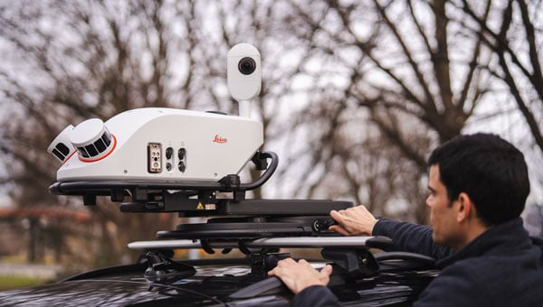
Leica Geosystems, part of Hexagon, has launched the Leica Pegasus TRK300, designed for various mobile mapping applications. As mobile mapping becomes increasingly important for collecting geospatial data, the technology supports smart city projects, infrastructure development and digital twin creation, improving urban planning and operational efficiency across industries.
With this new system, users with varying levels of experience can efficiently capture high-quality point cloud data. “The Pegasus TRK300 opens exciting opportunities for any business looking to enhance and grow their mapping capabilities, from identifying potholes to optimizing city center traffic flows,” says Christian Schäfer, business director mobile mapping at Leica Geosystems. “Because it is lightweight and designed with the user in mind, a single person can easily transport it and mount it to a vehicle, delivering results with minimal effort.”
Photo: Leica Geosystems
The Pegasus TRK300 features a multi-beam scanner system with two scanning heads that quickly collect high-resolution data from multiple angles, minimizing data gaps. With a range of up to 300 meters, the system covers wide corridors and large open areas, reducing the need for multiple passes. This capability allows users to map more ground in less time without sacrificing data quality, resulting in a high-density point cloud suitable for asset mapping and smart city modeling.
The Pegasus TRK300’s robust design allows it to operate in challenging conditions, including heavy rain and dust. Its seven-hour battery life supports a full day of fieldwork without frequent battery changes. The system complements the Pegasus TRK portfolio by offering a portable solution that balances advanced data capture with ease of use.
The Pegasus TRK300 integrates with Leica Pegasus FIELD for data capture and system monitoring and with Leica Pegasus OFFICE for advanced post-processing and final deliverables. This integration seeks to streamline workflows for mapping infrastructure, streets and assets, eliminating complicated file conversions or compatibility issues.
The Department of Homeland Security’s Science and Technology Directorate has released a new tool designed to help protect critical infrastructure that relies on GNSS: The GNSS Test Vector Suite and Distribution Methodology.
The GNSS Test Vector Suite and Distribution Methodology, now available on GitHub, is designed to help infrastructure operators assess and improve the resilience of their positioning, navigation and timing (PNT) systems. These systems are essential for sectors such as energy, transportation and telecommunications, and are vulnerable to disruptions from natural events, technical failures or cyber threats.
The tool suite provides standardized test scenarios and simulated data, allowing users to evaluate how their equipment responds to challenges such as signal interference or spoofing. By generating and converting simulated data into signals that mimic real-world GNSS systems, the tool enables independent testing of devices and systems for conformity to resilience standards.
“Accurate and precise Positioning, Navigation, and Timing information is vital to the nation’s critical infrastructure and is the backbone of the many services we depend on daily, from keeping our lights on to ensuring planes land safely,” said Julie Brewer, DHS acting under secretary for science and technology. “This new toolset gives people responsible for safeguarding these systems a way to independently test and strengthen them, ensuring our nation’s infrastructure is more secure against potential disruptions.”
The release of the GNSS Test Vector Suite supports Executive Order 13905, which seeks to protect essential PNT services across critical industries.
SpaceX has submitted reply comments to the Federal Communications Commission (FCC) detailing how its Starlink low-Earth orbit (LEO) satellite system currently provides, and could further support, positioning, navigation, and timing (PNT) services. The filing is part of the FCC’s ongoing Notice of Inquiry (WT Docket No. 25-110), which seeks to promote resilient and diverse PNT capabilities across the United States in response to vulnerabilities associated with the nation’s reliance on GPS, such as the risks of jamming and spoofing.
The FCC’s initiative, titled “Promoting the Development of Positioning, Navigation and Timing Technologies and Solutions,” aims to explore both space-based and terrestrial alternatives to ensure the continuity of critical PNT functions for national security, public safety, and economic stability. The agency is soliciting input from stakeholders on technologies that could complement or serve as alternatives to GPS, with a focus on robustness, geographic coverage and resilience to interference.
In response, SpaceX noted in its comments: “One opportunity stands out as a particularly ripe, low-hanging fruit: facilitating the rapid deployment of next-generation LEO satellite constellations that can deliver PNT as a service alongside high-speed, low-latency broadband and ubiquitous mobile connectivity.”
SpaceX also states that it has already been working on a PNT system for its cellular Starlink service, which is currently in public beta and is set to launch through T-Mobile in July. SpaceX outlines several technical features of the Starlink system that they argue are relevant to PNT applications.
Starlink Architecture and Features
SpaceX also noted that Starlink terminals can already provide nanosecond-level timing accuracy and meter-level positioning by using time-of-arrival measurements from its satellites. These capabilities allow the network to support precise timing applications, such as cellular network synchronization, without relying on external GPS sources. Timing signals are derived from the LEO constellation and synchronized through Starlink’s broadband infrastructure.
The filing highlights the Starlink system’s architecture, which includes thousands of satellites in low Earth orbit for global coverage and short signal travel times. SpaceX points to its phased-array user terminals, which use directional antennas to enhance signal integrity and mitigate interference. The company also notes that Starlink employs end-to-end encryption, making its timing and positioning information less susceptible to spoofing or tampering. According to SpaceX, Starlink is already in commercial use by a variety of customers and has been tested by U.S. military and civilian users in environments where traditional GNSS signals are degraded. The company emphasizes that these capabilities have been demonstrated under real-world conditions, not just in theory.
A Layered Approach to PNT
Addressing the FCC’s interest in a “layered” approach to national PNT resilience, SpaceX positions Starlink as one of several complementary solutions to enhance national PNT resilience. The company argues that using diverse, independently operated systems — both satellite and terrestrial — can provide redundancy and reduce dependence on any single technology or spectrum band.
SpaceX also responds to concerns from other stakeholders about whether Starlink qualifies as a PNT system, reiterating that the system was developed independently of government funding and can scale rapidly due to SpaceX’s vertically integrated manufacturing and launch model.
SpaceX confirms that Starlink operates in Ku- and Ka-band spectrum allocated for broadband services and is not proposing new spectrum allocations for PNT-specific use. It asserts that PNT functionality can be delivered within existing allocation.
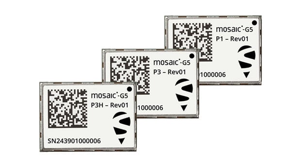
Septentrio, part of Hexagon, has introduced the mosaic-G5 series, expanding its line of compact GNSS receiver modules. The mosaic-G5 modules offer a 60% reduction in size and a 40% decrease in power consumption compared to the earlier mosaic-X5 receiver. The new modules measure 23 mm x 16 mm and weigh as little as 2.2 g, making them suitable for applications where size, weight and power are critical considerations, such as commercial UAVs, robotics and high-volume industrial equipment.
The mosaic-G5 modules offer reliable, high-accuracy positioning even in environments where GNSS signals may be degraded or obstructed. The mosaic-G5 product line includes several variants tailored to different use cases. The triple-band mosaic-G5 P1 is designed for high-volume applications, such as inspection drones and robotic mowers. The quad-band mosaic-G5 P3 and the triple-band heading module mosaic-G5 P3H offer enhanced positioning reliability in challenging conditions and are suited for applications such as delivery UAVs and light show UAVs. The P3H variant can calculate heading with a minimal baseline between two GNSS antennas, enabling accurate navigation for small autonomous device.
The new modules complement the mosaic product line, where the mosaic-X5 receiver remains as the benchmark for world-leading GNSS open signal anti-jamming and anti-spoofing resilience in a small form factor.
The mosaic-G5 modules complement Septentrio’s broader mosaic portfolio, which is recognized for its all-band GNSS technology, accuracy, reliability, and resilience to jamming and spoofing. The established mosaic-X5 receiver remains a benchmark for anti-jamming and anti-spoofing performance in a compact form factor. Like the mosaic-X5, the new modules are compatible with widely used open-source autopilots, such as PX4 and ArduPilot, simplifying integration and reducing development time. An evaluation kit, mosaic-go G5, is available to facilitate testing, and the RxTools user interface is provided for setup and evaluation.
Samples of the new mosaic-G5 P1, mosaic-G5 P3, and mosaic-G5 P3H modules are now available, with volume orders available for delivery later this year.
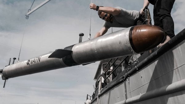
Vatn Systems — a defense technology company specializing in autonomous underwater vehicles (AUVs) for the U.S. military, its allies and commercial clients — has launched its new S12 AUV-torpedo product line. The company also opened a new manufacturing facility in Rhode Island, which is capable of producing up to 2,000 vehicles annually.
AUV-torpedo product line
Vatn Systems’ new 12.75-inch diameter AUV can operate as both a torpedo and an AUV in modular configurations. The Skelmir S12 is designed for deployment from submarines, surface vessels, or aircraft, and can support a range of missions, including torpedo operations, sensor delivery and electronic warfare.
The Skelmir S12, in its AUV configuration, has completed its first exercise. The initial production run has been sold to government customers, with deliveries expected this year. The torpedo variant is scheduled for manufacturing and delivery in 2026.
The company’s new manufacturing facility leverages patent-pending modular design and vertical integration techniques, enabling rapid production at a scale previously unseen in the underwater vehicle market.
Vatn recently partnered with Palantir to digitize its manufacturing process and provide AI-driven insights to accelerate the production of AUVs built in the new facility, which is expected to reach full production capability in July 2025.