ComNav Technology has released the SinoGNSS LS600 laser scanner, a handheld 3D scanning device designed for professional use in both indoor and outdoor environments.
It integrates lidar, GNSS, an inertial measurement unit (IMU) and dual-camera systems for detailed, colorized point clouds and precise positioning data production. The LS600’s also includes advanced SLAM algorithms, which work in tandem with a built-in real-time kinematic (RTK) GNSS module. This combination allows the scanner to achieve centimeter-level accuracy, even in challenging enviornments. The device’s high-speed lidar system supports 16-line and 32-line configurations, scanning up to 640,000 points per second with a 360° by 270° field of view. Detection ranges are available in both 120 m and 300 m options, accommodating a wide range of surveying applications.
The LS600 features dual 16 MP wide-angle cameras that capture vivid, multi-angle color data. This visual information is merged with lidar data through visual-aided SLAM, enhancing the color fidelity and detail of the resulting point clouds. One of the scanner’s notable features is its Flash Point Cloud Technology, which enables real-time visualization of point cloud data immediately after scanning. This allows users to validate data in the field and make necessary adjustments on site, reducing the need for post-processing and minimizing project delays.
In terms of workflow, the LS600 supports continuous, real-time positioning and data capture without the need for traditional loop closures, a step often required in standard SLAM processes. This advancement can decrease field time and improve overall efficiency. When operating in areas where GNSS signals are unavailable, such as basements or tunnels, users can establish ground control points for post-processing, maintaining high positional accuracy despite challenging conditions.
The scanner is equipped with removable, rechargeable lithium-ion batteries, each providing up to 1.5 hours of continuous operation. Fast charging capabilities and an LED power indicator support efficient field use. Data transfer is facilitated through a USB-C 3.2 Gen 2 interface, and the device includes a 512GB solid-state drive for onboard storage. Designed for handheld operation, the LS600 can also be mounted on a mobile vest or pole, offering flexibility and ease of use in various field situations. Its lightweight, all-in-one construction supports rapid deployment and straightforward operation.
The LS600 is suitable for a range of applications, including construction monitoring, as-built surveying, vegetation assessment, utility planning, urban renewal, mining and emergency response. Its combination of high accuracy, real-time visualization, and flexible deployment options is intended to improve data quality and operational efficiency for professionals across multiple industries.
For the first time, the oneNav L5-direct receiver was flown on a UAV through a simulated electronic warfare GPS signal interference field. The assessment took place Feb. 12 at the Emerging Technology Lab at U.S. Special Operations Command (USSOCOM). This non-classified evaluation replicated battlefield conditions, including variable speeds, altitudes, maneuvers and robust L5 signal interference.
Assessment Setup
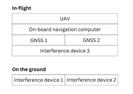
The assessment included two GNSS devices secured to the UAV, an onboard navigation computer and an onboard interference device. Two additional interference sources were located on the ground.
A simplified block diagram of the assessment setup. (Credit: oneNav)
The onboard navigation computer integrated data from both GNSS receivers to determine and maintain the vehicle’s position and guide its movement. GNSS 1 was a competitor L1/L5 dual-band receiver that uses the L1C/A signal for initial acquisition before adding L5 signals. GNSS 2 was the oneNav L5-direct receiver, which exclusively utilized modern L5-band signals for both acquisition and tracking.
Test Conditions and Results
The in-flight assessment, conducted on a UAV under real-world dynamic and RF interference conditions, demonstrated that the oneNav L5-direct receiver operates independently of legacy GNSS signals such as L1 and L2. While conventional dual-band receivers require L1 acquisition before transitioning to L5 tracking, the oneNav solution used only modern L5 signals for both functions6.
The Emerging Technology Lab implemented comprehensive RF interference protocols, including both ground-based and airborne signal interference across multiple L5 frequencies. The oneNav L5-direct receiver maintained tracking capabilities during L5/E5a signal interference centered at 1176.45 MHz. This performance is attributed to the receiver’s wideband RF front-end architecture, which enables simultaneous processing across an extensive frequency range. The system leverages Galileo’s dual sideband configuration (E5a and E5b), automatically transitioning to E5b when E5a experiences interference—a feature unique to the oneNav technology. A brief six-second delay was observed during this transition, reflecting a three-second lock loss on E5a followed by a three-second acquisition of E5b. The ability to track E5b signals, despite a 10 dB power differential, highlights the receiver’s sensitivity.
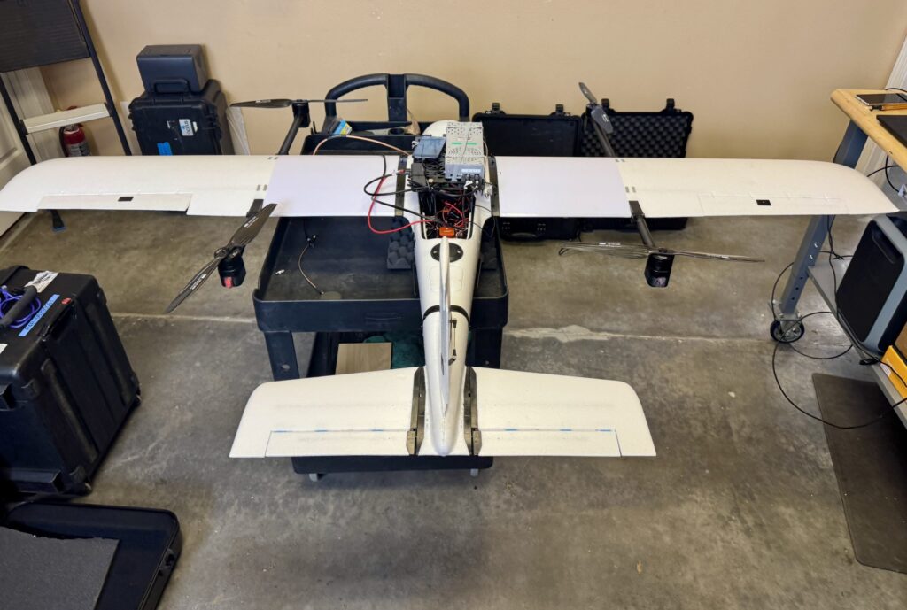
L5-direct FPGA attached to the assessment UAV. (Credit: oneNav)
Key Findings
The oneNav L5-direct GNSS receiver acquired, tracked and provided location data to the drone flight computer under actual flight dynamics and through L5 band signal interference.
Direct acquisition and tracking using only L5-band signals was demonstrated, confirming immunity to L1 signal interference.
The receiver demonstrated resilience to L5 in-band signal interference at typical electronic warfare power levels, quickly adapting by switching to the E5b sideband when E5a was disrupted.
The receiver maintained stability and responsiveness when both E5a and E5b sidebands were blocked.
Continuous tracking functioned well with the BeiDou constellation off and the almanac on or off6.
Technical Background
The oneNav L5-direct technology was originally developed for consumer applications such as wearables, phones and surface vehicles. Its adaptability allows for rapid customization and deployment across a range of platforms, including those requiring robust performance in challenging environments.
Because the L5-direct receiver uses signals exclusively within the L5 band, it can leverage the advanced features of these signals. L5-band signals offer greater power and increased resistance to RF interference compared to L1 signals. Industry experts, including Prof. Brad Parkinson, recognize the advantages of L5-only receivers for jam resistance.
Currently implemented on FPGA architecture, a future L5-direct ASIC is expected to deliver performance improvements, including enhanced acquisition and tracking capabilities.
Thales, a European leader in resilient navigation, announced a €55 million ($63 million) investment to expand its industrial sites in Châtellerault and Valence, France. The investment, scheduled between 2025 and 2028, aims to address increasing demand for advanced navigation solutions in both civilian and military sectors and to reinforce the company’s sovereign industrial base.
The company is responding to rising threats such as GNSS jamming and spoofing by deploying a suite of resilient navigation technologies. These solutions combine precision, autonomy and security, which are critical for maintaining operational continuity in military missions and civil aviation. Thales integrates inertial navigation systems with GNSS signal reception, enabling reliable navigation even in contested environments. The TopAxyz inertial navigation system ensures autonomous capability, while the TopStar-M receiver and TopShield anti-jamming technology protect signal integrity. These advancements are supported by France’s Directorate General of Armaments under the OMEGA program for the modernization of GNSS equipment for the armed forces.
At the Châtellerault site, Thales plans to quadruple production capacity for inertial navigation systems by 2028. With six decades of expertise in laser gyroscopes, this facility is the only European supplier equipping civil aircraft and will expand its offerings for aircraft, land vehicles, ships and munitions. In Valence, mass production of TopStar-M receivers and TopShield systems is set to begin in 2026. The site will also introduce a new production line for inertial MEMS sensors, a technology that combines compact design with high performance, positioning Valence as a leader in France’s MEMS technology sector for defense. The launch will be accelerated with support from Tronics Microsystems for specialized industrial expertise.
Currently, more than 800 employees work at the two sites, with plans to hire 150 additional staff by 2028. The investment seeks to strengthen Thales’ regional presence and contribute to France’s position in the industry.
Safran Federal Systems introduced BroadSim Genesis, the latest addition to its BroadSim product line, at the Institute of Navigation’s 2025 Joint Navigation Conference in the Greater Cincinnati area.
Developed for the U.S. defense community, BroadSim Genesis advances GNSS simulation and NAVWAR testing with significant improvements in signal capacity, operational flexibility and user experience. The system delivers high-fidelity, threat-representative environments designed to support next-generation positioning, navigation and timing (PNT) resiliency.
BroadSim Genesis can generate up to 2,000 signals, enabling advanced multi-constellation simulations across medium Earth orbit, low Earth orbit and alternative PNT sources within a single test environment. The system is engineered to meet modern NAVWAR requirements, supporting multi-antenna and multi-vehicle configurations, M-Code, and integrated jamming and spoofing capabilities to counter sophisticated signal threats.
The user interface features an integrated front panel with N-type connectors, removable drives and an onboard timing card, offering ease of use, security and field readiness.
“BroadSim Genesis is built for operators who demand flexibility, fidelity and performance in their GNSS simulation tools,” said Trevor Dougherty, vice president of sales at Safran Federal Systems. “Whether validating mission equipment, training for NAVWAR scenarios or assessing new PNT architectures, BroadSim Genesis gives defense users the edge they need”
The Spatial Sciences Institute (SSI), part of the Dornsife College of Letters, Arts and Sciences at the University of Southern California (USC), is a national leader in geospatial research and education. Founded on July 1, 2010, SSI has been educating students and professionals with both the theoretical foundation and hands-on technical training to advance spatial thinking and geospatial technologies.
Graduates solve complex problems across diverse industries and domains such as environmental sustainability, geodesign, public health, human security and geospatial intelligence. Education and training with GNSS are integral to SSI’s mission.
Addressing the Generation Gap
Despite its fundamental importance, the GNSS workforce is facing a growing generational gap as many experienced professionals near retirement, and fewer young individuals enter the field. This decline in incoming talent poses a critical challenge for industries that rely on high-precision positioning, from infrastructure development and environmental monitoring to national security and disaster response.
Part of the challenge stems from a lack of early exposure and awareness among younger generations about the relevance and applications of GNSS technology. Many students encounter the topic only indirectly, if at all, in traditional STEM or Geography curricula.
To preempt this generic approach, SSI has invested in high-accuracy GNSS receivers, RTK-enabled UAVs and immersive virtual/augmented reality visualization equipment to provide students the capability to translate the theoretical lessons in geodesy, spatial data acquisition, data analysis and integration into technical skills that result in actionable information.
Additionally, SSI has developed a range of experiential learning opportunities in GNSS to bridge the gap between classroom instruction and real-world GIS applications. While completing their coursework, students often solve the same real-world challenges as many industry professionals.
Engagement Through Experimental Learning
One such example is the undergraduate course SSCI 220L: Spatial Data Collection Using Drones, taught by Yi Qi, Ph.D., an associate professor with expertise in remote sensing and geospatial artificial intelligence. “When young students are introduced to imagery and geospatial technologies, one of the first questions they often ask is how the positions of real-world features are measured — and how accurate those measurements need to be for applications like building construction or urban tree mapping,” Qi explained. “This presents a great opportunity to introduce students to more advanced industry practices such as real-time kinematic (RTK) correction.”
Qi added, “We use the RTK-enabled DJI Mavic 3M drone for field data collections, which is often a highlight of the class.” One memorable field activity took place at the historic Los Angeles Memorial Coliseum, where students participated in drone flights alongside faculty. Before takeoff, they helped establish communication between the drone’s RTK system and the California Real-Time Network (CRTN), learning how to configure the system for centimeter-level accuracy. Later, they processed the imagery into high-resolution 2D orthophotos and 3D models. “This class benefits undergraduates by providing early exposure to GNSS,” Qi said. “This foundation is important for students to imagine their pathways in the geospatial industry and choose other advanced courses.”
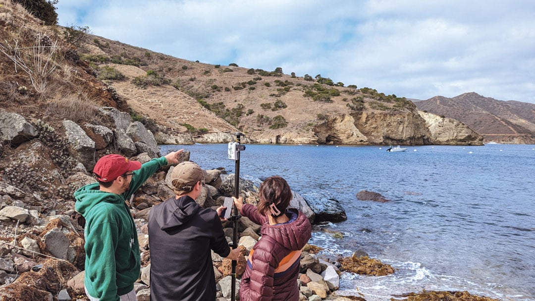
At the graduate level, as part of the SSCI 587: Spatial Data Acquisition course, students are required to participate in a week-long intensive-learning field experience at the USC Wrigley Institute for the Environment and Sustainability campus on Catalina Island. Laura Loyola, Ph.D., assistant professor in SSI with specialties in ecological physiology and field data collection, has led this course for many years and acknowledges that, “Catalina offers the ideal location for rugged terrain data collection, practice with online or offline mapping, and incorporates spatial data collection utilizing the RTK-enable UAV and high-accuracy GNSS receivers, with spatial analysis and visualization methods.”
While on Catalina Island, students meet with industry partners, such as Isaiah Mack, the owner of Eclipse Mapping and GIS, and an alumnus of USC, who bring professional experiences and the latest technology from industry. “The question now facing industry is whether the added investment in both hardware and training of personnel on high-accuracy GNSS receivers for spatial data collection is viable and needed for everyday uses, especially with RTK and satellite-based augmentation systems (SBAS) available,” Mack said. “The answer is overwhelmingly yes, with many mapping and GIS professionals utilizing centimeter-level RTK accuracy, so I feel it is important to share with students the growing market for these careers.”
Students quickly learn that without a viable connection, such as Wi-Fi or Starlink in remote areas, RTK capabilities in the UAV are limited. This requires the ability to incorporate high-accuracy ground control points into their collection workflows for georeferencing the drone imagery. As students work through the image processing and integration workflow, they gain firsthand experience in how GPS accuracy influences final image quality. Loyola noted, “In remote environments where WiFi connectivity is limited or non-existent, smartphone positional accuracy is decreased even more from the standard 30 cm to 50 cm, forcing students to work offline and with external GNSS receivers.”
Lastly, in certain field scenarios where students are unable to physically reach the survey target, they have learned to apply alternative methods to ensure accurate data collection. One effective technique involves using a laser rangefinder to measure the distance to the remote object. By combining this distance measurement with GNSS-derived position and bearing data, students can use in-app tools to calculate the location of otherwise inaccessible features. These experiences not only demonstrate their problem-solving abilities in challenging environments but also reflect a practical understanding of integrating complementary technologies to achieve high-precision geospatial results.
GNSS also has been integrated into the geodesign programs at SSI. Guoping Huang, Ph.D., is an associate professor with specialties in landscape planning and geodesign. “High-accuracy GNSS has become increasingly important in the architecture, engineering and construction sector due to the growing adoption of geospatial workflows,” he said. “These workflows span the entire project lifecycle — from spatially-enabled design tools that help create context-aware and environmentally responsive plans, to precision construction, where GNSS-integrated technologies such as sensor networks are used to monitor construction activities in real time.”
This integration ensures that construction adheres closely to the original design intent, minimizes costly deviations, and helps avoid damage to critical infrastructure. As a result, high-accuracy GNSS supports not only greater efficiency and accuracy but also enhances safety and sustainability in complex construction environments.
Empowering the Next Generation
By integrating GNSS into education programs and engaging students through practical fieldwork, faculty in the spatial sciences spark interest and develop the next generation of geospatial professionals. These efforts are essential to sustain the workforce and fuel innovation in a field increasingly critical to smart cities, climate science, autonomous systems and beyond. The experiential learning has inspired young generations to enter the geospatial workforce and make immediate, transformative impacts on existing practices.
Student Evelyn Vega commented, “The concepts and hands-on experience from course SSCI 220L helped me understand and appreciate GPS technology.” Recent graduate Yimiao Wang, who now works with the County of Riverside, California, has directly applied the GNSS data collection and processing techniques learned in course SSCI 587 to her work in roadway deterioration detection with RTK-enabled drone imagery. Her ability to leverage high-accuracy GNSS not only enhanced the quality and efficiency of her team’s outputs but also led to her career development success. These examples illustrate how GNSS education can empower students to drive innovation and advancement in the public sector and beyond.
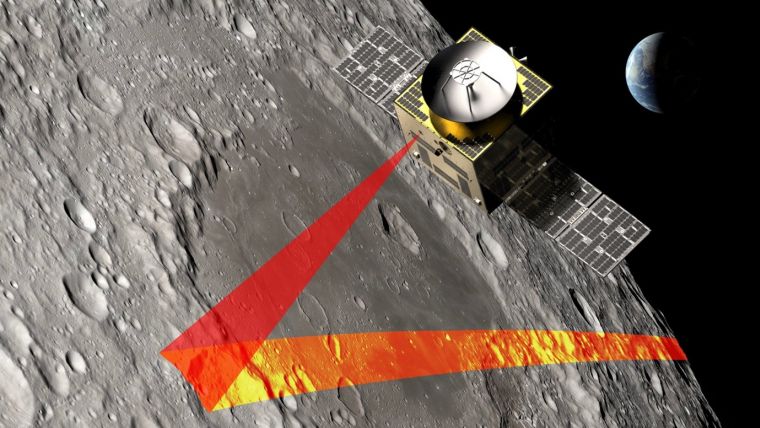
SFL Missions joins a team led by NUVIEW GmbH, which the European Space Agency has contracted to conduct a Pre-Phase A study for the Moonraker lunar mapping mission. This study launches under a new initiative for Small Exploration Missions. The Moonraker satellite will carry a laser scanner to create a detailed elevation map of the Moon’s surface.
The Moonraker mission will deploy a single orbiter in a low-altitude polar orbit around the Moon. The orbiter will host a lidar payload to capture highly accurate elevation points of the terrain. The team will use these data points to generate three-dimensional elevation models, which will guide the assessment and selection of future lunar landing sites.
Moonraker’s lidar data also seeks to advance broader scientific research. The mission will scan permanently shadowed regions to search for water ice and provide new insights into the Moon’s geology and internal composition. The Moonaker lidar will operate in two modes: one for broad-area scanning of the lunar polar regions and another for high-resolution surveys of specific areas of interest.
SFL Missions shared in a statement that Mission analysts are evaluating potential launch options and trajectories to efficiently enter lunar orbit. They are also studying how operational orbit parameters affect spacecraft design and payload data collection. The system design team focuses on accommodating the payload, configuring the spacecraft layout, and sizing subsystem components. They are designing the propulsion system to carry enough fuel for the transit phase and to maintain the operational orbit, compensating for disturbances from the Moon’s irregular gravity field. The team is developing detailed mission and system requirements to guide future design phases.
NUVIEW GmbH, based in Berlin, leads the Pre-Phase A study team, which includes several partners alongside SFL Missions. NUVIEW GmbH, a wholly owned subsidiary of NUVIEW Inc., is developing the world’s first commercial space-based LiDAR constellation for three-dimensional mapping of Earth.
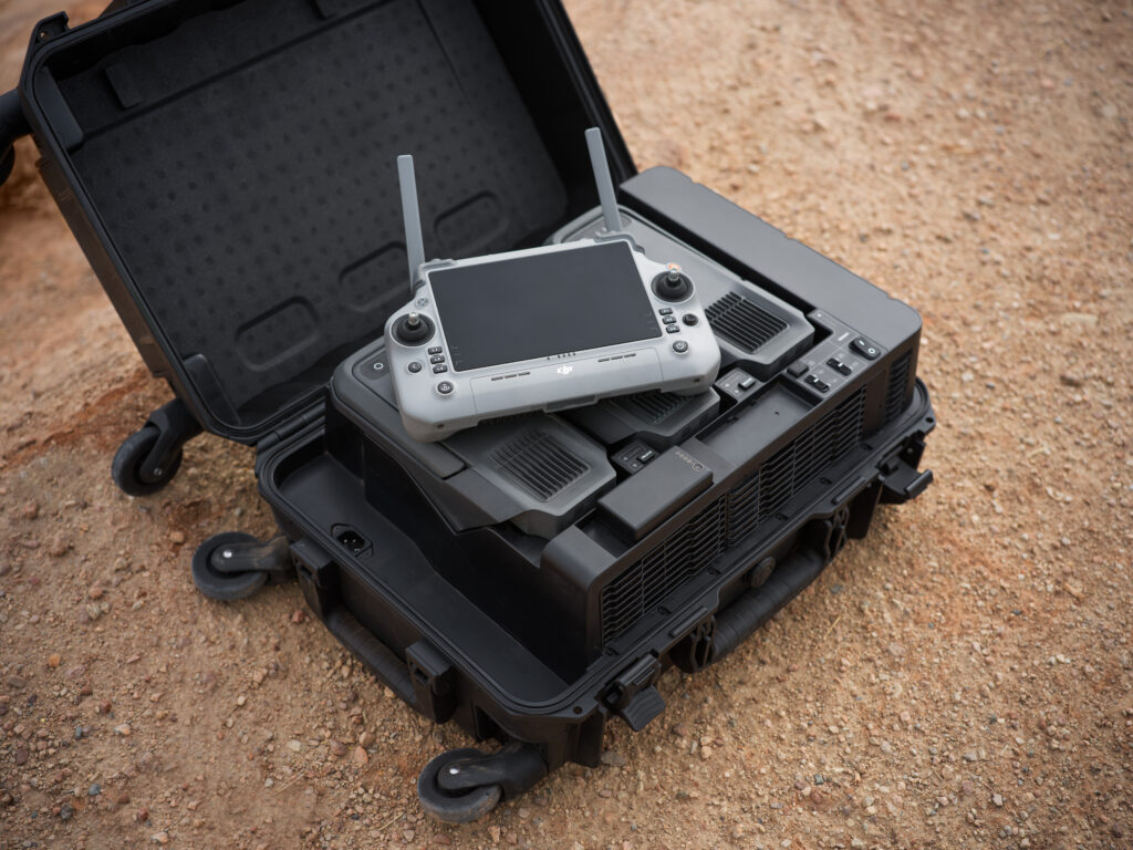
DJI has unveiled the Matrice 400, designed for a range of applications, including emergency response, power line inspections, large-scale mapping, engineering and construction. The UAV offers a maximum flight time of 59 minutes and can carry payloads weighing up to 6 kg. It is equipped with a lidar and millimeter wave radar-based obstacle sensing system, enhancing its ability to navigate complex environments.
The Matrice 400 features an IP55 protection rating, allowing it to operate in harsh conditions and withstand extreme temperatures ranging from minus 20°C to 50°C, according to DJI. The company also states that the drone is capable of taking off from stationary vessels and landing on moving ships, making it suitable for offshore operations such as wind turbine inspections and maritime patrols.
The UAV offers power-line-level obstacle avoidance, which allows it to detect and avoid buildings and mountains while flying at speeds up to 25 m/s. It uses O4 Enterprise Enhanced Video Transmission technology, which supports image transmission up to 40 km. This is achieved through a 10-antenna system on the aircraft and a high-gain phased array antenna on the remote controller. A built-in video transmission relay module allows operators to use one Matrice 400 as a relay drone, providing signal support for another unit.
The drone is designed for automated operations, featuring multiple intelligent functions to improve efficiency. It supports up to seven payloads simultaneously through four external E-Port V2 ports, with options for single or dual downward gimbals and compatibility with a third gimbal connector on the underside. DJI has also incorporated a range of privacy controls to address the data security needs of enterprise users.
NOTE: This article is adapted from an April 2025 U.S. National Grid Institute (USNGI) filing with the Federal Communications Commission (FCC) in response to an FCC Notice of Proposed Rulemaking on wireless location accuracy. The USNGI is a non-profit organization providing educational outreach and technical assistance to federal, state, local, and tribal governments, as well as commercial entities, to facilitate use of the USNG for a variety of purposes and, importantly, to support emergency responders in time critical situations (see usngi.org for more information). — Jules McNeff, GPS World Editorial Advisory Board
The term “golden hour” in medicine refers to the concept that rapid response is essential to improve chances of survival following a traumatic incident. Although the actual “golden” duration may vary, it encompasses the time required for incident detection and location, notification to the emergency call center, dispatch of responders, immediate triage and transport to an emergency medical facility. This timeline assumes that the incident location is clearly identified and effectively communicated to the call center and then to responders. Both the call center and the responders must also be educated in the use of geoaddresses. That is not always the case, and we are all familiar with situations where the location of responders was unclear or responders were misdirected, and victims died as a result.
Since its inception, GPS has been described as providing a “common-grid coordinate system” for users. While well-meaning, this is incorrect, as it does not account for real “coordinate system” differences. In fact, GPS employs a common reference frame, which defines the shape of the Earth based on the latest realization of WGS-84 within the International Terrestrial Reference Frame. People may then superimpose different coordinate systems over the global reference frame for the purposes of positioning, navigation, surveying, geodesy and other applications. These diverse coordinate systems are the “languages of location” that can result in confusion and operational friction if their uses are not deconflicted upfront; the consequences of which can prove fatal in emergency response situations, as emphasized here.
A Universal Language of Location
The Federal Communications Commission (FCC) has been working for years to address these deficiencies through improvements to E-911 services, both for wireline and wireless networks. Most recently, in March 2025, the FCC issued its (sixth) Notice of Proposed Rulemaking (NPRM) addressing wireless E911 location accuracy. In it, the FCC focused on requirements for more precisely determining three-dimensional locations, particularly the vertical component in structures. What is missing in this NPRM (and previous versions) is a clear understanding of the means to first identify the horizontal component of the incident location and report it to responders in unambiguous terms.
That missing element is a definition of which “language of location” (reporting format) should be used to identify incident locations to responders. With access to current technologies such as GPS and complementary positioning sources, it is natural to focus on the precision of location technologies. However, it is equally important to address specifically how a defined location is then reported to the responders who must locate it once they are dispatched. Modern technology can deliver precise three-dimensional locations, but the emphasis for responders must first be on understanding the horizontal component. If they do not arrive at the right horizontal geoaddress due to location reporting confusion, then the vertical component, even if it is relevant, does not matter.
The most common reporting format in urban and suburban areas is, of course, the street address. However, even within developed metropolitan areas, street addresses are not always consistent or definitive. In disaster situations, they may not even be present due to wind, flooding, fire or other physical destruction. They are also not useful in rural and remote areas away from established infrastructure. Another common format is latitude and longitude (lat/lon), which the public is aware of but not familiar with in terms of describing a specific location. Additionally, the use of lat/lon is complicated by the fact that it is a spherical system, and a location may be identified in any one of three different lat/lon versions, depending on how degrees, minutes and seconds are combined. Using the wrong version can lead responders far astray, resulting in lives lost. Other formats are available, but many are proprietary, difficult to understand, unfamiliar to the public and/or, most importantly, not directly available from proven position determination technologies such as GPS.
USNGI Presents a Solution
In its filing, the USNGI advocates that the FCC direct wireless communications providers to replace all references to civic (street) addresses and to latitude and longitude in reporting the horizontal component of incident locations with the term “U.S. National Grid (USNG) geoaddress.”It also recommends that the FCC consider rules under consideration that direct wireless providers to display USNG coordinates for horizontal addressing, using z-axis elevations provided by other technologies.
The USNG is a publicly available Federal Standard (FGDC-STD-011-2001) established in 2001 by the Federal Geographic Data Committee (FGDC) as a nationally consistent grid reference system and the preferred grid for National Spatial Data Infrastructure (NSDI) applications. The USNG creates horizontal geoaddresses that are unique, much easier to understand than latitude and longitude and always identifiable because they are referenced to a global grid and not to local features. In a simple format, the size of a telephone number, the USNG can define locations today to an accuracy of 10 m, far exceeding the 50 m requirement in the proposed rulemaking.
As noted above, USNG geoaddresses provide a clear and unambiguous way to describe locations in areas away from established road networks, or those affected by a natural disaster, where road signs have been destroyed. To make their use by the general public and emergency responders even easier, a variety of free smartphone applications are available today that provide continuous USNG geo-locations when activated.
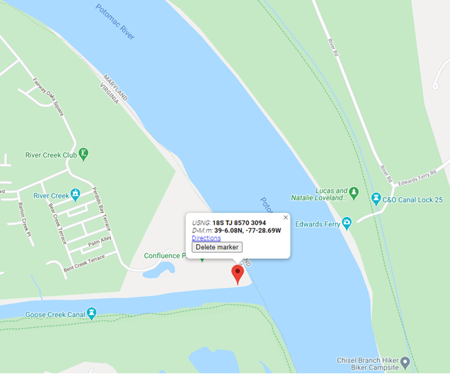
An object lesson is provided by one example (of many throughout the country), the drowning of a teenager named Fitz Thomas on the Virginia side of the Potomac River on June 4, 2020. This tragedy drew much local and even national attention. The teen was swimming at a small creek with friends in a park adjacent to a development, but without a street address. When he got in trouble, his friends tried to help and then called 911 on their cell phones, but could not describe their specific location. Because of the location confusion, coupled with jurisdictional failures, Fitz Thomas could not be saved. If the frightened teens had only been aware of, or had been asked/told by the 911 call center to give the center their geoaddress (which they could have gotten on their cell phones), all uncertainty about the incident location would have vanished immediately, and response could have been dispatched in the instant. The graphic shows the area with a 10 m USNG geoaddress, but which the group was not aware of at the time. The short geoaddress they needed was: TJ 8570 3094.
The location on the Virginia side of the Potomac River where Fitz Thomas tragically drowned on June 4, 2020.
Real-World Applications
USNG geoaddressing has been adopted by many federal agencies and by several state and local governments to facilitate emergency response operations:
The Federal Radionavigation Plan (FRP): The FRP, signed by the Secretaries of Defense, Transportation, and Homeland Security, states in Section 1.7.8 (Interoperable U.S. National Grid for Emergency Response Operations) that “…public availability of location-based applications in mobile electronic devices has highlighted the need to create awareness in the USG and among the public of a standard means to identify accident and other incident locations for emergency response purposes. Lack of a uniform method for describing incident locations has been a major impediment to rapid and effective emergency response in diverse metropolitan and rural areas.” It identifies the objective of the USNG standard “…to increase interoperability of location-based services by establishing a nationally consistent and preferred grid reference system to enable user friendly position referencing on gridded paper and digital maps in combination with GPS receivers and Internet map portals.”
The National Search and Rescue (SAR) Committee (NSARC): The NSARC designated the USNG as a preferred land search & rescue coordinate system in 2011. NSARC manuals specify use of the USNG as the primary georeferencing system for land SAR operations and for air-land SAR coordination. This aligns with coordination of military/civil responder operations as noted below.
The Federal Emergency Management Agency (FEMA): In October 2015, FEMA issued FEMA Directive 092-5, titled “Use of the United States National Grid (USNG),” which states as FEMA policy that, “FEMA will use the United States National Grid (USNG) as its standard geographic reference system for land-based operations and will encourage use of the USNG among whole community partners. FEMA will reference and employ the USNG in doctrine, relevant preparedness and grant programs, deliberate and crisis-action planning, training, exercises, operations, logistics, and other appropriate disciplines.”
Urban Search and Rescue (USAR): FEMA USAR teams adopted the USNG as a response to lessons learned during Hurricane Katrina and subsequently have deployed using the USNG in various disaster response operations. Also, during the aftermath of Hurricane Katrina and others, Delta State University in Mississippi produced a wide variety of map products incorporating the USNG to assist federal and state emergency responders.
In his statement relative to the proposed rulemaking, Chairman Carr noted a visit to Fire Station 40 in Fairfax County, Virginia. That is the home station for Virginia’s FEMA USAR Task Force 1, a world-renowned rescue team and early adopter of the USNG. The firefighters he met with that day may well have mentioned their use of the USNG in describing to him how location technology assists in the execution of their missions.
The DHS National Incident Management System (NIMS): The DHS NIMS identifies the USNG as “… a point and area location reference system that FEMA and other incident management organizations use as an alternative to latitude/longitude. The National Grid is simple to apply to support risk assessment, planning, response, and recovery operations. Individuals, public agencies, voluntary organizations, and commercial enterprises can use the National Grid within and across diverse geographic areas and disciplines. The use of the National Grid promotes consistent situational awareness across all levels of government, disciplines, threats, and hazards, regardless of an individual or program’s role.”
Joint Military/Civil Emergency Response Operations: As noted in the FRP, “The USNG is the civilian version of the Military Grid Reference System (MGRS) that the military uses for tactical operations. It enables geolocating incident locations from 100m to 1m precision.” A Chairman of the Joint Chiefs of Staff Instruction (CJCSI 3900.01E) on georeferencing states that, “To support homeland security and homeland defense, the USNG standard is operationally equivalent to MGRS.” As with the MGRS, the USNG is easy to learn by all levels of personnel, it is interoperable if used by civil and military first responders, it improves military support to civil authorities, and very importantly, it reduces operational friction and facilitates crisis and disaster response at all levels from federal to local government.
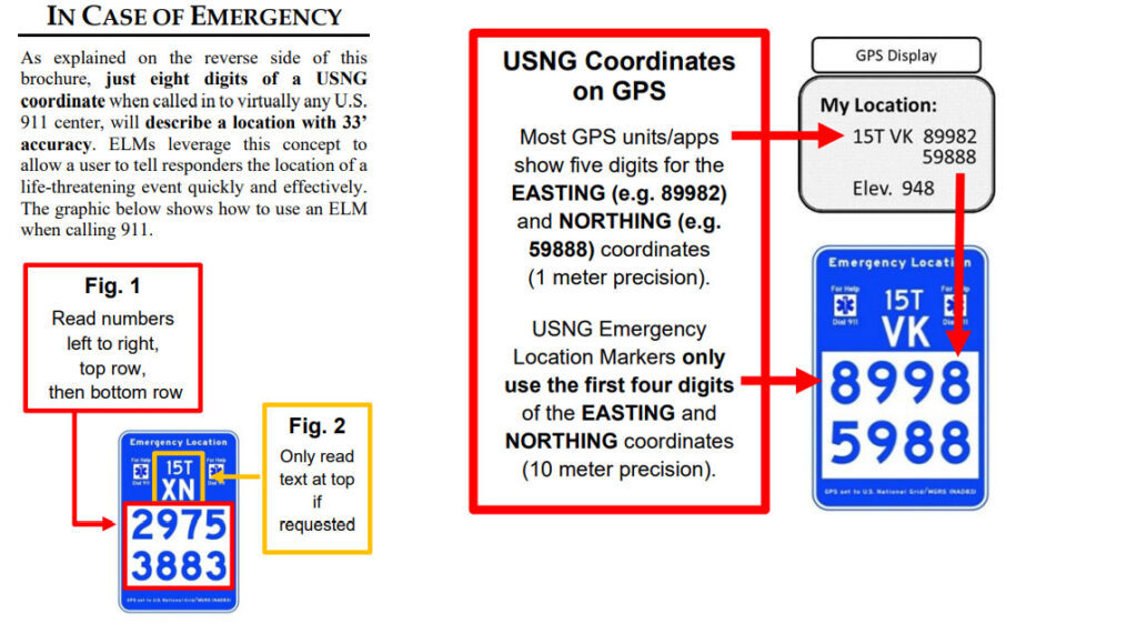
Emergency Location Markers (ELM): Localities in Minnesota, Georgia, Florida and other communities across the U.S., including National Parks, and even the Kennedy Space Center, have installed USNG-based ELM to give trail and park users a way to report an emergency location. Due to the disparate physical locations involved, nearly all such incident reporting can be expected to come from wireless systems, but to be enabled by reception of GPS positioning signals. The graphics below show the ELM relationship to GPS and how the reporting is facilitated by use of the USNG.
The ELM relationship to GPS and how the reporting is facilitated by use of the USNG.
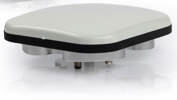
Calian GNSS has released its next-generation anti-jamming controlled reception pattern antenna (CRPA), the CR8894SXF+.
The CR8894SXF+ is an advanced CRPA, engineered to provide efficient interference protection and real-time situational awareness across critical infrastructure, marine, and defense environments where GNSS continuity is mission critical. The CRPA is specifically-designed to provide a low-power and lightweight solution in a compact size.
It features advanced in-band null forming to protect GPS L1/L2 and Galileo E1/E5b signals, helping ensure resilient positioning, navigation and timing in environments with contested, congested or degraded radio frequency conditions. The antenna incorporates Calian’s eXtended Filtering interference mitigation technology to maintain performance and reliability when RF threats are present.
The CRPA supports in-band null-forming of 20 dB to 40 dB and out-of-band rejection up to 80 dB across 700 MHz to 2,500 MHz. It includes two independent low-noise amplifier channels, allowing continued operation if one signal band is compromised.
The antenna forms nulls in both upper (L1/E1) and lower (L2/E5b) GNSS bands to actively suppress jamming sources. A serial output interface provides real-time feedback, enabling users to monitor RF conditions and system status. Outputs include:
CRPA state: open (no jamming), protected (jamming mitigated), or closed (jammed but protected)
Jammer characterization: azimuth and elevation angles of detected interference sources
Summary of threat signals, offering rapid threat assessment for command and control
The CRPA series aims to set a new benchmark in operational resilience, offering advanced protection and intelligence for mission-critical GNSS applications.
My previous newsletter highlighted a National Geodetic Survey (NGS) webinar held on April 25, 2025, titled “Design of Networks Using NOS NGS 92,” given by Dave Zenk, NGS northern plains regional advisory.
[Authors note: Dave Zenk told me that he is retiring from the National Geodetic Survey on May 31, 2025. Dave’s presence will be deeply missed. His dedication and spirit have left a lasting impact on NGS’s products and services. I hope his retirement is filled with joy, relaxation, and new adventures.]
In addition to Dave Zenk’s retirement, several other NGS Regional Geodetic Advisers have retired or left NGS employment over the past several months. Click here for a list of the current advisors, along with the names of interim contacts handling inquiries for those advisors who have retired or departed from government service.
As previously mentioned, Dave showed a well-presented outline of the tables that users need to be familiar with when using OPUS Projects to process and submit GNSS projects to NGS for publication. It should be noted that users submitting data to NGS must follow the guidelines outlined in NOS NGS 92.
I found the webinar to be very informative, and I would encourage all users of OPUS Projects to download the presentation. During the webinar, Zenk briefly mentioned three items that I believe deserve more explanation for anyone using OPUS Project. This newsletter will address the following topics in more detail:
The mark’s classification — primary, secondary, and local — will not be included on the NGS datasheet, but the local and network accuracy from the project will be provided on the datasheet. What does this mean to someone who’s using the mark in their project?
OPUS Project uses the F-statistic test to determine if the appropriate constraints were imposed during the horizontally and vertically constrained adjustments. Why does OPUS Project use this statistic?
The Constraint Ratio (CR) test, computed by OPUS Projects, provides a method for identifying which coordinates should be constrained and which should not be considered for constraints in the final horizontally and vertically constrained adjustments. What’s the best way to use this table?
First, the presentation discussed the tables that described the procedures for establishing three different mark classifications — primary, secondary and local. It also mentioned that the classification will not be included on the NGS datasheet but the local and network accuracy from the project will be provided on the datasheet. See the image below.
Photo: NGS website
What does this mean to someone who’s using the mark in their project? Since the NGS data sheet will provide the network and local accuracy from the project, users can determine if the accuracy value of the mark meets the requirements of their project. In my opinion, the network and local accuracy from the project provide a better indication and understanding of the level of trust of the published coordinate.
As previously mentioned, anyone submitting a GNSS project to NGS for publication must adhere to the NOS NGS 92 guidelines. During the presentation, Zenk provided several examples that depicted correct network designs. I would encourage everyone to download the NOS NGS 92 document and Zenk’s presentation to gain an understanding of the classifications and the network design requirements to meet a particular classification.
Adhere to NOS NGS 92 guidelines (Photo: NGS website)
Anyone who submits an OPUS Project to NGS for publication knows that the constrained adjustments must meet the requirements of the F-statistic test. So, what is this test, and why does OPUS Project require this statistic? Essentially, it is a method of verifying whether the appropriate constraints were applied during the horizontally and vertically constrained adjustments. The F-test evaluates the ratio of two variances; that is,
The F-test checks whether this ratio is significantly different from 1, which would suggest the models have significantly different fits to the data. The result is compared against the critical value from the F-distribution based on the degrees of freedom from the constrained adjustment and the degrees of freedom from the minimally constrained adjustment, and a chosen significance level alpha (e.g., 0.01). NGS OPUS Project uses an alpha level of 0.01% or 99% confidence level.
Once the adjustment has been deemed acceptable i.e. all shifts and residuals are reasonable, the F-test should pass. The F-test is a statistical test that helps determine if the variance (variance of unit weight) from a fully constrained adjustment is significantly different from the variance (variance of unit weight) of a minimally constrained adjustment. The variance of unit weight is a critical statistic and should be looked at carefully when evaluating adjustment results. If the fully constrained adjustment fits well with all selected control (the constraints), the value of the variance of unit weight should be close to 1.0. The F-test is performed using a 99% confidence level.
So, if the constrained adjustment statistics differ significantly from the minimally constrained adjustment, then there could be an issue with the constraints. Of course, this is assuming that the minimally constrained adjustment variance of unit weight indicates that all data outliers have been eliminated. So, why are constraints important?
OPUS Project first calculates GNSS coordinates in a minimally (free) network adjustment, which defines relative positions but not their absolute placement in space. Without constraints the entire network can float and/or rotate.
Constraints are important in GNSS network adjustments because they:
Anchor the network in a geodetic datum; in this case, NAD 83 (2011), epoch 2010.0.
Ensure a unique and stable solution that reflects the physical world.
Make the network useful for engineering, mapping, and scientific purposes.
Control point coordinates (from previous surveys or known datums) often have inherent errors or uncertainty. Constraining coordinates exactly assumes zero error, which is rarely true. Weighted constraints let you assign a realistic level of trust to known published coordinates by using error estimates. OPUS Project applies weighted constraints based on input error estimates (OPUS Project denotes these as sigmas of the coordinates), which allow for minor deviations in the constrained coordinates. The weighted constraint methodology provides flexibility to network adjustments by recognizing that published coordinates have some uncertainties and allows constraints to take on small corrections leading to more accurate and consistent network solutions. Although, it should be noted that the adjusted coordinates of the constraints from the final horizontally constrained adjustment are not updated in the NGS database even though there are minor deviations to their final adjusted values.
If the F-test fails, it is due either to the errors (sigmas) of the constraints being overly optimistic (too small) or the constrained coordinates not agreeing with the observations (causing excessively large shifts of the constrained coordinates). Failure of the F-test does not automatically mean the constrained adjustment is bad. It is a flag that indicates there may be a problem with the constraints, and that they should be investigated. In addition, the F-test assumes of a normal (“bell-shaped”) probability distribution of the residuals. Networks with a distribution that is significantly non-normal may fail for that reason, even when a constrained adjustment is acceptable.
if your adjustment fails the F-test, what do you do? How do you determine which constraint or constraints should be unconstrained? OPUS Project provides some information about the constraints that can be helpful in determining a bad constraint. The CR test, computed by OPUS Projects, provides a method for identifying which coordinates should be constrained and which should not be considered for constraints in the final horizontally and vertically constrained adjustments. What’s the best way to use this table? The box titled “Constraint Ratio” from NGS’s Online OPUS Project User Guide — (Section 12.7.3.2. Analyzing the Horizontal Constrained Adjustment) provides a good explanation with an example of using the constraint ratio table (12.7.3.2. Analyzing the Horizontal Constrained Adjustment). Basically, this statistic highlights coordinate shifts that are significantly larger than expected based on the sigma provided by the user. That is, coordinates that have a very small sigma should not be expected to change as much as coordinates with a very large sigma. The CR value is compared to a critical value of 3.0, which corresponds to a t-statistic at the 99% confidence level. Therefore, any constraint ratios greater than three should be investigated and are candidates to be unconstrained (see the box titled “Constraint Ratio”).
Constraint Ratio
If the F-test fails, it is possible that some constraints need to be freed up. It might be the case where some of the shifts are too large. The CR test provides a way of identifying where the bad shift might be. The CR is essentially a Students T Test, with the absolute value of the shift between the adjusted, constrained coordinates and the published coordinates, divided by the sigma (σ, or standard deviation) used to constrain the station. It is computed for each component (north, east, and height):
OP provides the CR for all marks in the final table in the output summary given in the body of the email or in the Processing Report (.txt), as shown below in Fig. 12.21.
Fig. 12.21 Constraint Ratio Test as seen in the Processing Report of the Horizontal Constrained Adjustment. (Photo: NGS)
Computed CRs are compared to the critical value or 3.0, corresponding to a T-statistic at a 99% confidence level. If the value of CR is greater than 3.0 for any of the three components, that indicates that there may be a problem with the constrained station.
I find these statistics very helpful when determining which coordinates should be constrained in the final adjustments. I hear that some users select all possible constraints and then start releasing marks based on the CR table. That certainly is one way of doing it but could be time-consuming and confusing. That said, the first thing I do is compare the minimally constrained adjusted coordinates to the published coordinates to determine if there are any obvious outliers. This has been helpful to me in large GNSS projects located in subsidence regions such as the Harris-Galveston, Texas, region of the United States.
One final note on OPUS Project
On May 22, 2025, NGS issued a notice to users, announcing the implementation of the International Terrestrial Reference Frame 2020 (ITRF2020). The announcement provided the following information addressed to all Active OPUS Project Users.
Active OPUS-Projects Users,
In early June, NGS will implement the new International Terrestrial Reference Frame 2020 (ITRF2020) and IGS20 realizations in the U.S. National Spatial Reference System (NSRS) in order to maintain consistency with the International Earth Rotation and Reference System Service (IERS) and the International GNSS Service (IGS) reference frames. This results in updated North American Datum 1983 (NAD 83) coordinates for stations in the NOAA CORS Network (NCN), kept at epoch 2010.0. This update is called the Multi-Year CORS Solution 3 (MYCS3), and it follows NGS’s MYCS2 effort from 2018.
OPUS-Projects users with active projects are advised that open projects will need to be reprocessed from the beginning in ITRF2020.
If projects are close to completion, users have the option of submitting them to NGS before the transition using the currently published NAD83(2011/MA11/PA11) coordinates transformed from ITRF2014. The deadline for submissions is June 6, 2025 for those wishing to take this route.
Above, I bolded several sentences that will be important to users currently performing projects using OPUS Projects. That is, all projects not submitted by June 6, 2025, will need to be reprocessed from the beginning in ITRF2020.
Users should continue to check NGS’s website for announcements regarding the transition from the alpha site to the beta site. Future newsletters will address the Multi-Year CORS Solution 3 (MYCS3) and will highlight the beta products as they are released.
BAE Systems unveiled a diverse line of M-code GPS receivers at the Joint Navigation Conference in Cincinnati, rounding out an extensive line of products that ensure U.S. warfighters have the most dependable GPS systems available across sea, land and air.
M-code is a military GPS signal designed to improve anti-jamming capabilities and provide enhanced security. BAE Systems’ security-certified Common GPS Modules (CGMs) leverage the robust M-code signal across an all-inclusive GPS receiver line. The portfolio scales from the world’s smallest and lowest-power M-code GPS for size, weight, and power (SWaP)-challenged applications, to highly robust receivers with integrated anti-jam antenna electronics for exceptionally challenging environments.
BAE Systems’ diverse line of M-code receivers are next-generation GPS solutions for airborne, weapon, and ground platforms, including handheld form factors. This includes:
ASR-M
DIGAR-300M
MPE-M
MicroGRAM-M
NavFire-M
NavGuide
NavStrike-M
NavStorm-M
SABR-M
The company anticipates deliveries of the NavGuide handheld to customers will begin this year.
BAE Systems is also set to deliver a future generation of GPS products based on Military GPS User Equipment (MGUE) Increment 2 technology, developed as part of the MGUE Increment 2 Miniature Serial Interface (MSI) program. The technology will improve the performance of military position, navigation, and timing (PNT) equipment and provide resilience against attacks on GPS signals.
BAE Systems has provided selective availability anti-spoofing module products to more than 45 countries and is delivering M-code GPS receivers in multiple form factors and levels of capability to the U.S. armed forces and its allies through foreign military sales.
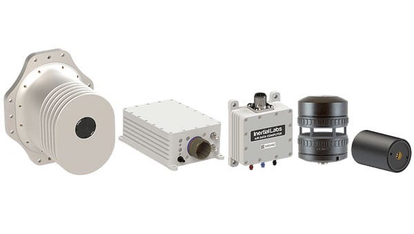
Inertial Labs, a VIAVI Solutions company, has introduced its Visual-Aided Inertial Navigation System (VINS), designed to help aircraft maintain accurate flight paths in environments where GPS/GNSS signals are unreliable.
The launch follows a report from the U.S. Department of Transportation noting a rise in GPS jamming and spoofing incidents across North America and much of Western Europe. These disruptions, which now reach up to 700 cases worldwide each day, impact both commercial and military operations. War zones have seen the highest concentration of interference, with Lithuanian airspace alone recording more than 800 cases in the last three months of 2024. Communications and emergency services, which depend on precise timing and geolocation, are also affected.
VINS is engineered for unmanned aerial vehicles to complete long-range missions in GNSS-challenged environments. The system leverages Maxar Raptor 3D vision-based positioning software, which estimates a vehicle’s absolute 3D position by comparing onboard camera imagery — day or infrared —with Maxar Precision3D satellite-derived maps using Perspective and Point principles.
In GNSS-denied conditions, VINS can maintain a horizontal position within 35 m, a vertical position within 5 m, and velocity within 0.9 m per second of true values. It also holds heading accuracy within 1° and pitch/roll within 0.1°. With GNSS enabled, the system achieves a horizontal position of 1 meter, vertical position under 2 m, velocity accuracy of 0.03 m per second, heading within 0.1 °, and pitch/roll within 0.03°.
The modular system is designed for low-altitude operation and includes processing and sensor modules, a GNSS or CRPA antenna, an air-data computer, and a digital windspeed sensor for use with both fixed-wing and multi-rotor UAVs. Optional features include a commercial off-the-shelf radio for data and absolute positioning in GPS-denied environments, as well as Iridium low-earth orbit (LEO) GNSS and M-Code/SAASM GNSS receivers.
Inertial Labs and VIAVI will demonstrate VINS and the second-generation RSR Transcoder with GPS full constellation simulator at the 2025 Joint Navigation Conference (JNC), held June 2-5 in the Greater Cincinnati area. The products will be on display at the Inertial Labs (booth 430) and VIAVI (booth 406) stands.
VIAVI and its Inertial Labs division will also present three sessions at the conference:
“3D Vision-Based Positioning for Autonomous Aerial Platform Navigation and Human-in-the-Loop Reconnaissance Mission,” presented with Maxar, Monday, June 2 at 1:50 p.m. ET.
“Anti-Jam/Spoof Phased Array Antenna,” Wednesday, June 4 at 10:50 a.m. ET.
“Retrofitting At-Risk GPS Defense Equipment with a Multi-Orbit LEO and GEO Clock System for Resilient PNT Services,” Wednesday, June 4 at 11:30 a.m. ET.