The Iridium 9604 module and development kit streamline global IoT development with integrated satellite, cellular and GNSS connectivity
Iridium Communications has announced commercial availability of the Iridium 9604 module and Development Kit, giving developers, OEMs and solution providers a faster path to build and scale connected IoT solutions worldwide.
Combining GNSS positioning, Iridium short burst data satellite connectivity, and LTE-M cellular, the Iridium 9604 module delivers a compact, integrated solution for global IoT deployments.
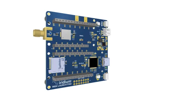
The Iridium 9604 Development Kit, back side. (Credit: Iridium)
Alongside the Iridium 9604 Development Kit, developers can rapidly prototype, test and validate hybrid satellite, cellular, and GNSS applications with resources that simplify integration and streamline deployment workflows.
Built on the u-blox SARA-R5 platform, the Iridium 9604 is designed to reduce hardware complexity, lower integration costs, and accelerate time to market for connected solutions operating across industrial, infrastructure, transportation, mobility, utilities, maritime and remote-monitoring applications. The integrated design helps reduce board space requirements by 60 percent or more while simplifying RF routing, power architecture, and firmware development, Iridium said.
Early developers and beta participants reported significant operational and economic benefits from the platform’s integrated architecture.
“The Iridium 9604 has enabled us to develop a truly global asset tracking solution without relying on terrestrial network infrastructure. Its reliable coverage, compact form factor, and straightforward integration have significantly accelerated our development process and allowed us to focus on optimizing the end-user experience,” said Askar Gabit, CEO, GPSOne. “For applications in remote and challenging environments, the Iridium network provides the confidence that critical data can be delivered when it matters most.”
The Iridium 9604 gives developers independent control over satellite, LTE-M and GNSS subsystems, enabling flexible implementation of failover logic, location-aware connectivity decisions, and application-specific routing strategies. A unified AT command set and comprehensive SDK resources further simplify development and integration.
Built for scalable and power-sensitive IoT applications, the Iridium 9604 features a compact 16 x 26 x 2.4 mm form factor optimized for deployments where size, resiliency and efficiency are critical. The platform supports GPS, GLONASS, Galileo and BeiDou GNSS services alongside LTE-M (Cat-M1) and Iridium’s 100% global L-band satellite network.
The Iridium 9604 represents the next evolution of Iridium’s broader IoT strategy, expanding beyond traditional satellite-only hardware to support unified, multi-mode connectivity architectures. The Iridium network now supports multiple IoT pathways, including dedicated Iridium SBD modules, Iridium NTN Direct standards-based direct-to-device capabilities, and larger payload connectivity through the Iridium Certus 9704 module.
Operating on a global mobile satellite network, the Iridium 9604 delivers reliable connectivity across remote land areas, oceans, airways and polar regions where other networks are unavailable or unreliable.
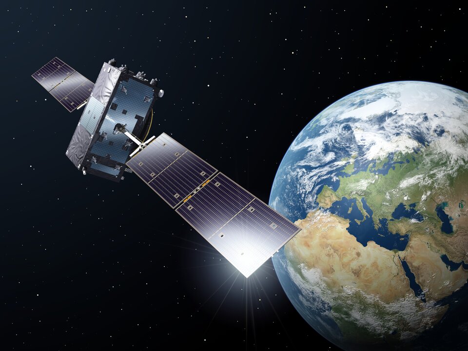
In April, Galileo marked a step forward with the deployment of a new signal component, known as E5a Quasi Pilot, on 12 satellites of Europe’s satellite navigation constellation. This upgrade makes Galileo signals easier to access, particularly on emerging mass-market, low-power devices used for Internet of Things and smart city applications.
With the world’s most precise satellite navigation system, a constellation of more than 30 satellites and five billion of users worldwide, Europe’s Galileo continues to strengthen its position at the forefront of global navigation satellite systems (GNSS).
Galileo signals, like other GNSS signals, traditionally consists of two components: pilot signals and data signals. The first ones are data-less and help enable the receiver to acquire and track the signal, while the second carry all the navigation information needed to pinpoint the target’s location.
But what if this traditional concept could be rethought to respond to emerging market needs, particularly for users seeking faster and simpler acquisition?
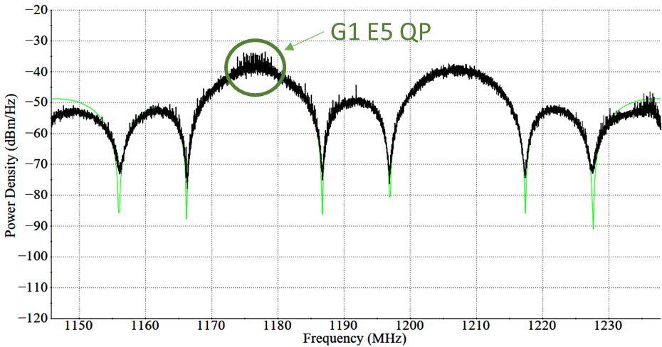
The European Space Agency and its industrial partners have developed a solution targeted at mass-market applications that require low power: E5a-QP, a Quasi-Pilot (QP) signal component transmitted in Galileo’s E5 band.
The signal component is broadcast free of charge and now available for implementation in both new and upgraded chipsets, enabling all users of the Galileo Open Service to benefit from its capabilities.
A small addition for a big computational deduction
Quasi-Pilot means a pilot signal that retains its intended role but also carries a small amount of data, including the time information necessary for a first fix. This time information is fully predictable at user level. A Quasi-Pilot signal component is also characterised by a tailored signal structure that simplifies the acquisition process, which reduces the power consumption on the receiver’s end.
This proves particularly useful for low-power, basic receivers such as those found in smartphones, smart-city infrastructure, internet-of-things devices and those that only need to receive a GNSS signal for a very small time to determine their position (also known as ‘snapshot’ devices).
The deployment of E5a-QP also represents a key enabler for low-power receivers designed to process signals exclusively in the E5 band, rather than relying on signals in the E1 band. In this way, the resilience of the receiver against spoofing and jamming attacks is increased, as the fundamental acquisition process is no longer only dependent solely on E1 signals.
Test campaigns have demonstrated that E5a-QP can reduce signal acquisition time by a factor of three, while substantially lowering the number of operations required for acquisition by a factor of eight.
The introduction of this new Galileo signal component follows an extensive series of design, testing and validation that demonstrated the value of the signal and the feasibility of implementing new signal components on current Galileo satellites.
Starting 2020, a design phase explored how to reconfigure the Galileo satellites’ payload to integrate the new signal component. Following on, a series of tests were run on engineering models at ESA’s Navigation Payload Laboratory to demonstrate the feasibility and performance benefits that can be achieved with the new signal component.
In 2023, the solution was then validated using an in-orbit test bench: a duo of Galileo satellites operating in an elliptical orbit reconfigured to transmit the new signal component. The signal was measured at Galileo In-Orbit Test facility at ESEC in Belgium and DLR’s Signal Monitoring Facility in Germany, and successfully acquired and tracked by a set of receivers at ESTEC in the Netherlands.
First generation updated, second generation in mind
Between November 2025 and April 2026, twelve Galileo satellites were updated to accommodate this new signal component, marking the completion of this deployment.
This critical mass of satellites ensures that at least one of the satellites used to compute a position fix transmit the Quasi-Pilot signal at medium to high elevation angles, making sure that users around the world can benefit from the performance gains.
Honeywell has launched Kestrel, a compact navigation solution designed to help uncrewed aerial systems (UAS) operate reliably in contested environments where GPS signals may be degraded, jammed or spoofed.
Built to support the growing demand for smaller, more affordable and highly efficient platforms, Kestrel combines Honeywell Aerospace’s HG3900 MEMS inertial measurement unit with an M-code receiver and a multi-GNSS receiver. The platform is intended to meet the specific needs of Group 2 and 3 collaborative combat aircraft and loitering munitions platforms. It is also suitable for crewed aircraft where size, weight, power and cost are important considerations.
“Kestrel reflects the evolving needs of today’s uncrewed operations, where operators are looking for resilient navigation technology that is smaller, lighter and more cost-effective,” said Matt Picchetti, vice president and general manager of Navigation & Sensors at Honeywell Aerospace. “This system helps operators maintain mission objectives in environments where legacy GPS systems are lagging behind.”
Kestrel is an Embedded GNSS/INS (EGI) system for global defense and commercial operators in need of advanced inertial navigation technology with secure positioning capabilities in a smaller footprint. The system is 40 percent smaller and lighter than similar navigation products while delivering up to an 80 percent improvement in navigation accuracy for uncrewed platforms. It also reduces costs by as much as 50 percent, helping operators efficiently scale deployment across high-volume drone operations. Kestrel’s resiliency reduces UAS attrition by 60 percent, while more than doubling the capacity for mission distances.
The ability to operate without assured GNSS access is a distinct advantage for any military aircraft operating in contested or GNSS-denied environments because it provides continuous, self-contained position, velocity and attitude estimates independent of external signals.
Kestrel is designed to support a broad range of defense and commercial applications and will be available in configurations that support international and non-ITAR deployments.
Honeywell pioneered EGI technology and has produced more than 60,000 units since the mid-1990s to meet customers’ most challenging navigation, pointing, stabilization and flight-control applications.
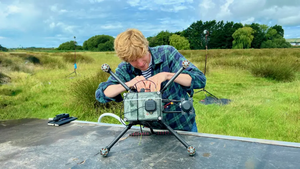
42 Technology (42T) and Omnisense have demonstrated a safer autonomous drone landing system when GNSS signals are unreliable.
The system uses a ground-based ultra-wideband (UWB) positioning technology. It was developed by Omnisense through its European Space Agency-supported DroneHome program.
Autonomous landing is a safety-critical phase for drone missions, particularly challenging when GNSS is impaired due to signal obstruction, reflection or interference (near tall buildings, in busy ports, or inside tunnels).
The DroneHome program uses terrestrial radio positioning as a complementary navigation layer within the overall navigation system, so a drone’s position remains stable and predictable even in GNSS-challenged environments. In practice, this means autonomous systems can maintain controlled behavior instead of experiencing sudden navigation failures.
One of the key technical challenges was extending the operational range of UWB positioning to make it viable for autonomous landing. 42T worked closely with Omnisense to design and develop the extended-range RF hardware used in both the ground infrastructure and airborne elements of the system. The front-end design incorporates a UWB system-on-chip with low noise amplification, power amplification, switching, and antenna integration to deliver the required range and performance.
Field trials and simulation-based analysis confirmed that the system maintained stable positioning within a defined envelope during GNSS-degraded operation, enabling reliable autonomous approach and landing.
The results from Omnisense’s DroneHome program are directly relevant across a wide range of applications, including airborne, terrestrial and maritime operations, infrastructure inspection, and autonomous systems operating in GNSS-challenged environments.
DroneHome was a focused development and validation programme exploring extended-range terrestrial positioning for autonomous navigation applications. The project was led by Omnisense in collaboration with Mozaero and supported by ESA under the NAVISP program.
The project is framed within the COINCIDENTE Programme, the Spanish Ministry of Defence’s National R&D Plan, which seeks innovative technological solutions of interest for defense. It will also benefit from the support of institutions such as AICIA (Association for Research and Industrial Cooperation of Andalusia, University of Seville) and FADA-CATEC (Advanced Aerospace Technologies Centre).
The main objective of FENIX is the design, development and validation through simulation and flight test campaigns of a technological demonstrator for an autonomous control and coordination system for heterogeneous unmanned aerial vehicle (UAV) swarms.
The system will build on Alpha Unmanned Systems’ existing UAV platforms, as project lead, and on the advanced autopilot technology of UAV Navigation-Grupo Oesía. Building on this foundation, new technologies will be developed to endow the swarm with collective intelligence, in alignment with military doctrine. These technologies will analyze, assess and demonstrate how the use of such systems enhances effectiveness and efficiency in surveillance and reconnaissance tasks in complex and contested environments, while also providing increased robustness.
Key developments and objectives of the project include:
Swarm coordination and planning system: Capability for efficient, real-time replanning in response to unforeseen events.
Cooperative perception system: Integration of multisensor data collected by the different UAVs, enhancing detection accuracy and robustness against occlusions, concealment and adverse weather conditions.
Advanced capabilities for critical missions: Identification and mapping of areas of interest under GNSS signal interference (jamming) or spoofing, as well as in NRBQ (CBRN) threat scenarios, and detection of specific targets in patrol, reconnaissance, target acquisition, and search-and-rescue missions.
The use of a heterogeneous UAV swarm will enable these missions to be carried out more effectively and efficiently, directly enhancing defense operational capabilities. The FENIX system operator will only need to define the mission to be executed by the swarm through a single human–machine interface.
The system will automatically decompose the mission defined by the operator into simple tasks, optimally allocate these tasks to the UAVs within the swarm according to their capabilities and constraints, and generate and assign safe, efficient and physically feasible trajectories for each UAV, while respecting kinematic constraints, energy limitations, communication range constraints, and other operational factors.
The FENIX Project, supported by the advanced intelligence of UAV Navigation-Grupo Oesía’s GNC systems and Alpha Unmanned Systems’ rotary-wing platforms, represents a significant step forward in the use of UAV swarms for military applications. This project provides a robust and efficient tool for inspection and reconnaissance in complex and contested environments.
Focal Point Positioning, a U.K.-based developer of GNSS-enhancing software, has launched Precise+, a technology designed to deliver reliable high-precision positioning in environments where conventional carrier-phase tracking struggles. The company unveiled the technology at the 2026 European Navigation Conference in Vienna, Austria.
Precise+ extends the capabilities of the company’s patented Supercorrelation platform into the carrier-phase domain, targeting the cycle slips that can cause real-time kinematic (RTK) and precise point positioning (PPP) systems to lose lock in difficult environments.
Continuous carrier-phase lock is required for centimeter-level positioning. In dense urban areas, under tree cover and in multipath-heavy environments, interruptions can trigger cycle slips and force systems to reinitialize. According to the company, these disruptions remain a major obstacle for advanced driver-assistance systems (ADAS), automated driving and robotics applications.
Focal Point said Precise+ improves GNSS performance in challenging conditions, delivering sub-meter accuracy in scenarios where commercial receivers using live corrections typically produce multi-meter errors.
The company tested its software-defined Precise+ receiver in Thetford Forest, a common benchmark environment for GNSS testing under dense foliage. According to Focal Point, the system achieved 80 cm accuracy at the 99th percentile, meaning positioning error remained below 80 cm for 99% of measurements collected in the most difficult sections of the route. The company said competing state-of-the-art receivers produced errors greater than 3 m under the same conditions.
Focal Point noted the results were achieved using only receiver-level performance, without inertial sensors, dead reckoning or sensor fusion. The company said the improvements can be combined with additional technologies such as sensor fusion, RTK or PPP corrections.
“RTK and PPP deliver centimeter accuracy in open sky but degrade sharply where signals are disrupted by tree cover, buildings or multipath,” said Scott Pomerantz, CEO of Focal Point Positioning. “This limits deployment to a narrow slice of the road network, not the environments people actually drive in.”
“Meanwhile, correction services carry high recurring per-vehicle costs yet cannot fix what happens at the receiver when the signal environment degrades,” Pomerantz added. “This means OEMs pay for precise positioning that doesn’t function where it matters most.”
According to the company, Precise+ is designed for automotive applications including ADAS, automated driving and vehicle-to-everything (V2X) systems, as well as other applications requiring sustained high-precision GNSS performance outside open-sky conditions.
Taoglas has launched the GVLB208 series, an active and passive dual-band GNSS L1/L5 stacked patch antenna — the first in a new family of ultra-compact antennas.
Combining a tiny package with concurrent L1/L5 support and stable right-hand circular polarization (RHCP), the antennas deliver reliable centimeter-level positioning in a compact 20 x 20 x 8 mm footprint.
The GVLB208 series is designed for applications that require high-precision positioning in a compact form factor. Its size, dual-band support and circular polarization make it suitable for designers looking to improve positioning performance without increasing device footprint.
The new antennas address this challenge with a single-feed stacked patch design that supports concurrent L1 and L5 GNSS bands. By leveraging dual-band operation, they significantly reduce the impact of multipath interference, enabling more reliable positioning and improved accuracy in complex RF environments.
The series delivers dual-band L1/L5 performance typically associated with larger GNSS patch antennas. The antenna achieves peak gain of up to 1.5 dBi, approximately 50% efficiency across both bands, and an axial ratio of around 4 dB, supporting stable RHCP signal reception and consistent positioning performance.
Optimized for major global GNSS constellations, including GPS, Galileo, GLONASS and BeiDou, the GVLB208 series supports reliable operation across varied RF environments.
The passive GVLB208 A single-feed architecture enables dual-band L1/L5 performance without the complexity of multi-feed designs, while its pin-mount configuration simplifies RF layout and integration. It can be easily implemented on standard PCB designs, with optimal performance achieved on a typical 70 x 70 mm ground plane.
The active AGVLB208.A, including active electronics and filters, is supplied with 1.13 micro-coax cable and an I-PEX MHF I connector for easy integration with the latest multiband GNSS modules.
The GVLB208 series is suitable for autonomous delivery robots requiring seamless sidewalk navigation and precise drop-offs, where every centimeter counts. It also supports applications including unmanned aerial vehicles (UAVs), telematics systems, fleet and asset tracking, precision agriculture, and industrial IoT deployments.
Taoglas plans to expand the GVLB208 family later this year with an active SMD variant with integrated active electronic components, designed for automated high-volume manufacturing.
The rapid growth of autonomous military systems is creating a new challenge for the defense industry, working to keep equipment operating when navigation becomes unreliable.
Across recent conflict zones and contested regions, GNSS disruption is affecting UAVs, loitering munitions, ISR platforms, maritime systems and autonomous ground vehicles.
“InfiniDome is expanding its vision beyond GNSS protection, toward a future of mission continuity and navigation awareness in contested environments,” the company stated.
The statement reflects a broader trend across the defense autonomy sector. While anti-jamming technologies were once treated primarily as protective add-ons, many military programs are now integrating navigation resiliency into wider autonomy architectures. The result is a growing shift in how autonomous systems are evaluated.
Rather than focusing solely on navigation accuracy or platform performance, defense organizations are increasingly asking whether autonomous systems can maintain operational continuity under degraded or denied conditions. Industry observers note that this transition is particularly evident in the loitering munition and tactical UAV sectors, where survivability in contested environments is becoming a baseline operational requirement.
At the same time, low-SWaP anti-jamming capabilities are becoming more common across the market, increasing pressure on companies to differentiate beyond hardware alone. That pressure appears to be accelerating a broader industry movement toward what some describe as “navigation awareness,” the ability not only to withstand interference, but also to understand and react to the electromagnetic environment in real time.
InfiniDome is expected to demonstrate this direction during the exhibition through IroNav, developed jointly with Wonder Robotics. The demonstration will include autonomous operation streamed live from a jammed environment in Israel, showcasing navigation resilience capabilities under active interference conditions.
The live demonstration comes as European defense programs continue increasing investments in autonomy, tactical drones, and resilient battlefield systems amid growing concerns surrounding electronic warfare and GNSS vulnerability.
New feature eliminates the need for a self-hosted NTRIP caster and delivers enterprise-grade correction data to up to three devices simultaneously at no additional cost to the operator
Onocoy, a decentralized GNSS reference station network, is launching Loop Back, a new platform feature that routes quality-assured RTK correction data back to each station operator’s own devices free of charge. More than 7,800 active reference stations contribute to the onocoy network.
Operators who also needed precision positioning for their own drones, survey rovers, precision agriculture equipment, or autonomous machinery face a common friction point: the reference station they owned and operated produces valuable correction data, but routing that data back to their own field equipment requires either a separately maintained NTRIP caster or an additional subscription. Loop Back eliminates both.
Loop Back is immediately available to all onocoy station operators as a standard platform feature. Full documentation and setup guides are available at docs.onocoy.com.
How Loop Back works
When a GNSS reference station is connected to onocoy, raw observation data flows from the operator’s hardware into onocoy’s quality validation pipeline. The platform continuously checks position stability, multi-constellation health (GPS, GLONASS, Galileo, BeiDou), uptime and other parameters before producing a quality-assured RTCM 3 correction stream.
That validated stream has two destinations simultaneously: enterprise data clients who purchase GNSS reference station data through onocoy’s pay-per-use model, and the station operator’s own devices via Loop Back. The operator receives the same production-grade correction stream used by commercial clients, free of charge and with no data credits consumed.
Key capabilities at launch:
Up to three simultaneous active connections from an operator’s own devices to their own station’s corrections, with unlimited devices configurable
Compatible with any NTRIP-capable station regardless of hardware brand or model
Quality monitoring identical to that applied to enterprise client streams
No separate NTRIP caster required; onocoy manages the infrastructure
Free of charge: No data credits consumed for the operator’s own station data.
Who benefits
Loop Back is designed for the growing segment of professionals who both operate a reference station and rely on precision positioning in their daily work. Target use cases include:
Precision agriculture: Farmers running auto-steered machinery, UAV-based crop monitoring, and variable-rate application systems
Geomatics and surveying: Professionals running a base station and multiple rover units across a site, eliminating the overhead of a local base-rover setup
Autonomous systems, robotics and drones: Operators deploying multiple vehicles or aircraft requiring cm-accurate positioning for mapping, inspection, or delivery workflows
Research: Academic and scientific teams running parallel measurement campaigns from a shared base station.
Economics of station operation
Most professionals who deploy a GNSS reference station do so because their business in precision agriculture, surveying, drone operations and construction demands one. By connecting that station to onocoy, operators put the same hardware to work a second time: contributing data to onocoy’s global network and earning rewards worth several hundreds of U.S. dollars per year.
That additional income is enough to amortize the station in under two years before accounting for potential savings on subscriptions. Because onocoy applies continuous quality monitoring to every stream, operators also safeguard the positioning accuracy their business depends on.
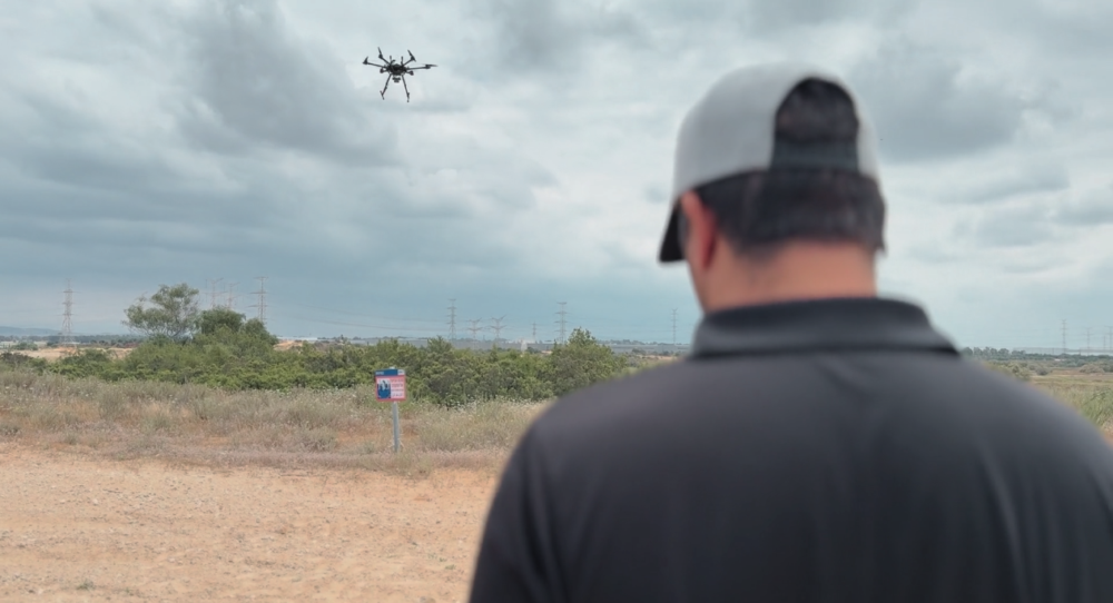
On a January morning in 2026, a GPS jammer powered up near Shiraz, Iran. It was not the first, and it would not be the last. The Strait of Hormuz corridor has become one of the most persistently jammed airspaces on Earth. But this time, two satellites were watching from very different vantage points, and together they would demonstrate something new: that spaceborne sensors can localize a terrestrial GPS jammer to within a few kilometers, using physics alone.
This article presents the first direct comparison of Cyclone Global Navigation Satellite System (CYGNSS) — a NASA GNSS reflectometry constellation — and NASA-ISRO Synthetic Aperture Radar (NISAR) — an L-band synthetic aperture radar for GPS jammer localization. The results challenge assumptions about which modality performs better and reveal that the answer depends on a question most analysts forget to ask.
The setup: Known jammer, known position
Validation requires ground truth. With help from the PNT community, we identified a GPS jammer operating near 27.32°N, 52.87°E (approximately 50 km southwest of Shiraz) that was active on Jan. 8 and Jan. 20, 2026, with confirmed quiet periods on Dec. 15 and Dec. 27, 2025. The jammer’s position was established through independent signals intelligence.
This gave us a controlled experiment: two “jammer ON” dates and two “jammer OFF” baseline dates, with satellite coverage from both CYGNSS and NISAR spanning the full period.
Two satellites, two physics
CYGNSS is a constellation of eight microsatellites that measure GPS signals reflected off Earth’s surface. Each spacecraft carries a delay-Doppler receiver that maps reflected signal power across a grid of delay and Doppler bins, known as the delay-Doppler map, or DDM. When a terrestrial jammer is active, it floods the GPS band with noise, elevating the DDM noise floor and suppressing the coherent surface reflection. The effect is detectable hundreds of kilometers from the jammer, creating a wide-area footprint in the reflected signal data.
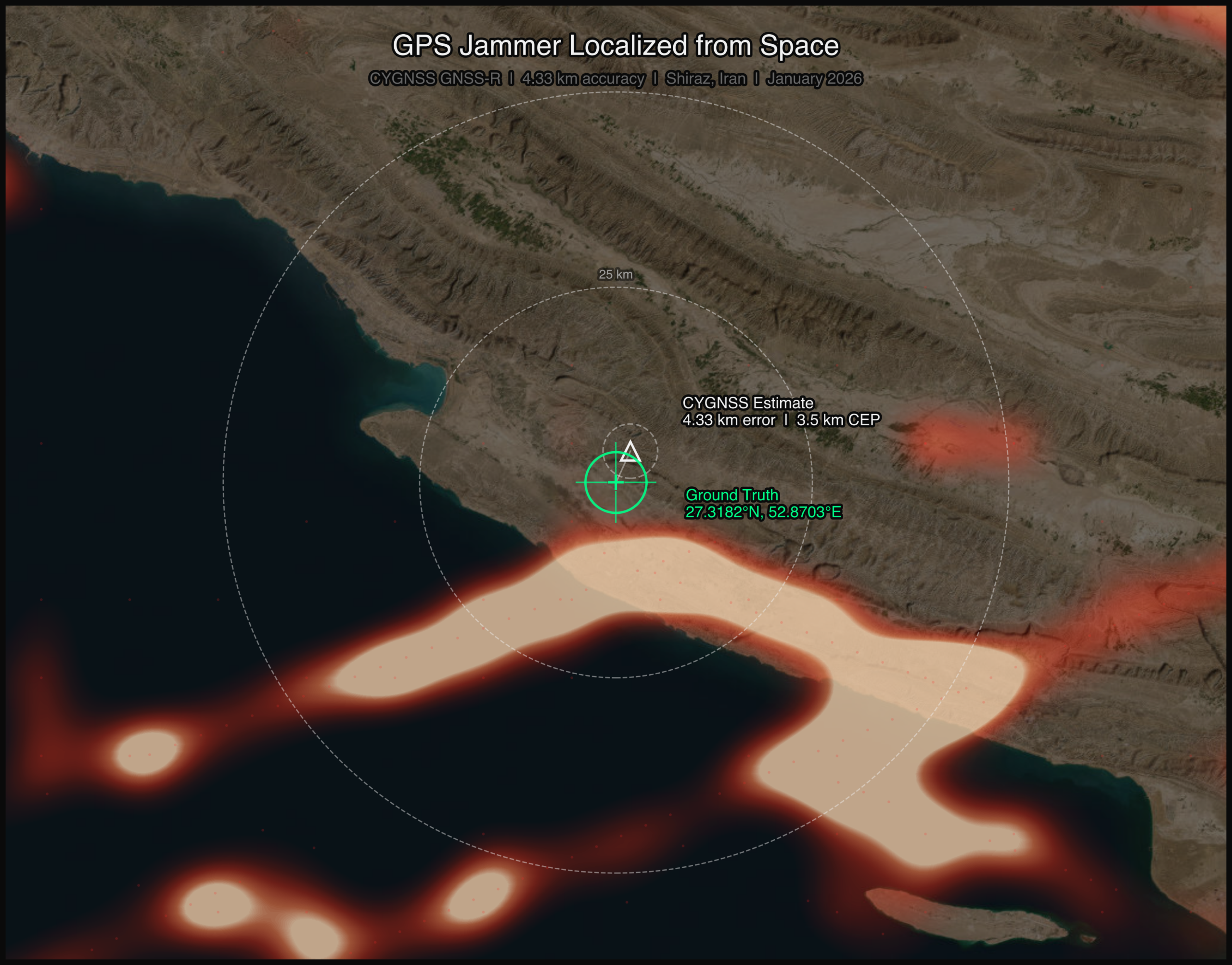
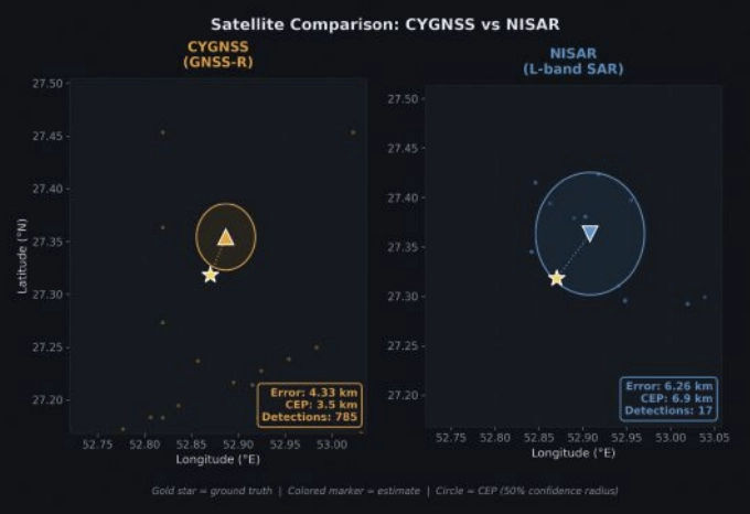
FIGURE 1 Jammer localization tracks from both CYGNSS and NISAR satellite constellations. (All figures by Sean Gorman)
NISAR operates an L-band SAR at 1.257 GHz, just 30 MHz from the GPS L2 frequency at 1.2276 GHz. When a GPS jammer’s broadband emissions leak into NISAR’s receive band, they create characteristic streaks in the SAR imagery. The streaks are elongated in the cross-track (range) direction, not along-track, a counterintuitive result that follows directly from SAR signal processing. In azimuth (along-track), the jammer is a fixed-point source with a valid Doppler history, so the SAR azimuth processor focuses it correctly, similar to any ground target. But in range (cross-track), the jammer’s broadband noise does not match the SAR’s chirp waveform, so range compression smears the energy across many range bins rather than compressing to a point. The result is a streak perpendicular to the flight direction, whose along-track centroid encodes the jammer’s latitude and whose cross-track extent encodes a range arc, which is the distance from the orbit ground track (FIGURE 1). The bearing of each streak encodes the jammer’s direction relative to the satellite’s ground track.
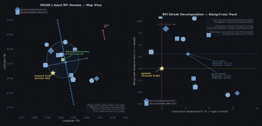
FIGURE 2 Crosstrack visualization for NISAR RFI streaks.
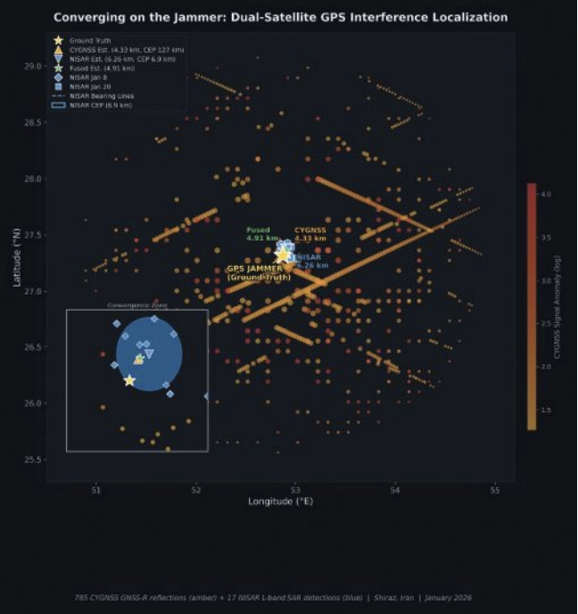
The two sensors could hardly be more different. CYGNSS sees the jammer’s effect on reflected GPS signals, offering an indirect measurement spread across hundreds of specular reflection points. NISAR sees the jammer’s emissions directly in its own receiver, which is a more precise measurement, but only along the satellite’s narrow ground track. FIGURE 2 shows both detection sets converging on the jammer location.
CYGNSS: 785 Detections, 4.33 km Error
We processed all CYGNSS Level 1 data within 200 km of the jammer location on both ON and OFF dates. Four detection methods contributed observations:
■ DDM noise floor (419 detections): The pre-computed ddm_noise_floor variable, calibrated against the thermal noise reference, proved the strongest discriminator. Near-jammer values exceeded 15,000 counts against a ~10,000 mean background.
■ Spatial noise grid (299):A 10 km gridded analysis identified cells with anomalously elevated noise relative to adjacent cells.
■ SNR hole detection (66): Coherent surface reflections were suppressed near the jammer, creating spatial “holes” in the SNR field.
■ NBRCS drop (1): Surface reflectivity dropped approximately 16% near the jammer, though this method produced few threshold exceedances.
Across four DDM channels per spacecraft and multiple passes, this yielded 785 total anomalous observations on the jammer-ON dates.
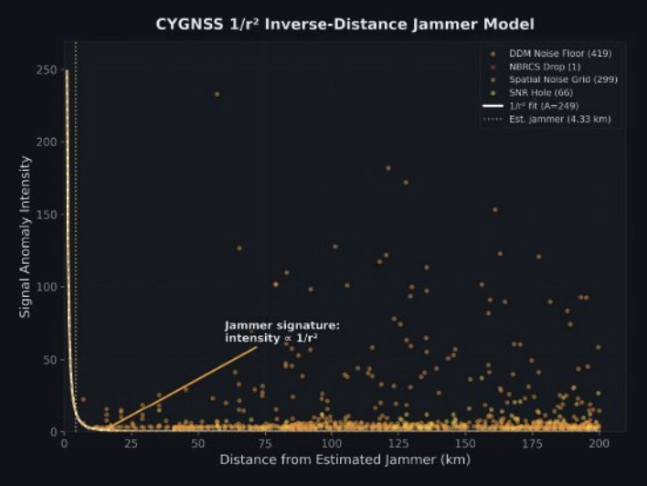
FIGURE 3 Scatterplot of interference insensity versus distance for CYGNSS.
Localizing using a simple centroid of all 785 detection positions placed the jammer 32.1 km from truth, with too many distant, low-SNR detections diluting the estimate.
Instead, we fit a parametric 1/r² inverse-distance model:
I(r)=Ar2
where A is a free amplitude parameter and r is the distance from a candidate jammer position. We jointly optimized the jammer position and amplitude using SciPy’s Nelder-Mead optimizer across all 785 observations, weighted by intensity. The optimizer converged on a position 4.33 km from ground truth, providing a 27.7 km improvement over the centroid (FIGURE 3).
The baseline: Zero false positives
On the jammer-OFF dates (Dec. 15 and Dec. 27, 2025), the pipeline produced exactly zero detections using the same thresholds, geographic area and satellites: a completely clean result. This suggests that the 785 detections are unlikely to be sensor artifacts or geographic anomalies. They disappear when the jammer turns off.
NISAR: 17 Detections, 6.26 km Error
NISAR’s approach is fundamentally different. Rather than measuring hundreds of reflected signals across a wide area, it captures direct emissions in a narrow swath, but with far greater geometric precision.
We processed NISAR L2 GCOV (geocoded covariance) products from Track 157, Frame 15 (ascending) for three dates: the Dec. 27 baseline and the Jan. 8 and Jan. 20 jammer-ON passes. The detection pipeline used eigenvalue decomposition of the polarimetric covariance matrix:
λ₁ ratio thresholding: In jammer-contaminated pixels, the dominant eigenvalue λ₁ of the 2×2 [HH, HV] covariance matrix rises sharply relative to the scene mean, indicating an unpolarized additive source.
Cross-polarization ratio (HV/HH): GPS jammer emissions are unpolarized, disproportionately elevating the HV channel. Anomalous HV/HH ratios flag contaminated azimuth lines.
Iterative outlier trimming: Three rounds of 1.5σ clipping removed scattered false detections, leaving 17 high-confidence streak centroids.
FIGURE 4 Error and CEP Metrics Comparison for CYGNSS and NISAR.
With detections from two passes on different dates, we had two independent bearing lines. Each pass’s streak centroids defined an azimuth aligned cluster whose major axis pointed toward the jammer. A PCA fit to the two clusters extracted the bearing: 308.1° from the Jan. 8 pass and 316.2° from Jan. 20. Their intersection — computed via scipy optimization of the angular residual — landed 6.26 km from ground truth (FIGURE 4).
The along-track/cross-track decomposition reveals why the 6.26 km error is a geometric ceiling for this dataset, not a processing limitation. Both passes come from the same Track 157 ascending orbit on a 12-day repeat cycle. The intensity-weighted along-track centroids land at +3.0 km and +3.1 km north of the jammer, a direct stable latitude measurement. The cross-track centroids land at +5.4 km and +5.6 km east of the orbit ground track, a range measurement. But because both passes share identical orbit geometry, the two range arcs are nearly parallel. The bearing difference between passes (308.1° vs 316.2°) is only 8.1°, producing a shallow intersection angle and poor cross-range resolution. A single descending pass, which would cross the ascending track at approximately 60-70°, would transform the geometry from two near-parallel lines to a genuine triangulation, potentially reducing the localization error to sub-2 km. Unfortunately, no descending NISAR pass covering this jammer site was available in the beta archive, which ends on Jan. 20, 2026.
The CEP (circular error probable, the radius containing 50% of repeated estimates) was 6.88 km, meaning if we ran this analysis on many similar jammers, half our estimates would fall within ~7 km.
Who wins?
CYGNSS wins, and not just on accuracy.
A naive confidence metric for the 1/r² fit would be the scatter of the 785 input detections (CEP = 127 km). But the detections are not the estimate; they are the inputs to a model fit. The relevant confidence question is: How stable is the fitted position?
We answered this with a 500-iteration bootstrap: resample the 785 detections with replacement, re-run the 1/r² optimizer each time and measure the spread of the resulting position estimates. The bootstrap CEP, the median radial distance across 500 fitted positions, was 3.48 km. The optimizer converges stably to within a few kilometers of the same location regardless of which detections are included.
This means CYGNSS achieves 4.33 km error with 3.48 km confidence, both better than NISAR’s 6.26 km error and 6.88 km confidence.
The bootstrap CEP also reveals what the raw scatter obscures: the 1/r² fit is constrained primarily by the ~80 high-intensity detections within 30 km of the jammer. The remaining 700 distant, low-intensity detections contribute little to the position estimate — they are correctly downweighted by the intensity-weighted least squares. The fit’s stability comes from the physics: a 1/r² signal has steep gradients near the source, providing strong positional constraints where it matters most.
Bayesian fusion: Can we get both?
The obvious next question: Can we combine CYGNSS’s wide-area sensitivity with NISAR’s geometric precision? We implemented four fusion strategies, all designed to work without ground truth:
■ Bayesian Gaussian posterior: Model each sensor’s estimate as a 2D isotropic Gaussian with σ = CEP/1.1774. The posterior is the product of the two Gaussians: an analytical precision-weighted mean.
■ NISAR-prior constrained 1/r²: Re-run the CYGNSS optimizer with a Gaussian regularization term pulling toward the NISAR estimate, sweeping the regularization weight λ from 0.01 to 10.
■ NISAR-proximity re-weighted 1/r²: Apply a Gaussian kernel centered on the NISAR estimate to the CYGNSS detections before fitting, effectively upweighting observations consistent with the SAR result.
■ Joint CEP-balanced: Combine the CYGNSS gradient signal with NISAR cluster proximity, weighted by (σ_CYGNSS/σ_NISAR)².
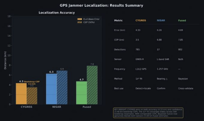
FIGURE 5 Summary statistics for jammer localization with CYGNSS, NISAR and fused approach.
With the bootstrap CEP, the precision ratio flips. The CYGNSS Gaussian (σ = 2.95 km) is now 2× tighter than NISAR (σ = 5.84 km). The Bayesian posterior, the precision-weighted mean, lands at 4.69 km, pulling toward CYGNSS’s better estimate while incorporating NISAR’s independent geometric constraint. FIGURE 5 shows the fusion: two comparable Gaussians whose product is tighter than either alone.
The fused result (4.69 km error, 7.85 km CEP) is not quite as accurate as CYGNSS alone (4.33 km), because NISAR’s 6.26 km estimate pulls it slightly away from truth. But operationally, the fusion provides a cross-validated answer: two independent physics arriving at similar locations builds confidence that neither sensor is producing an artifact.
The key insight is that the bootstrap CEP unlocked meaningful fusion. When the raw scatter CEP (127 km) was used, NISAR dominated the posterior 343:1 and fusion added nothing. With the fit-based CEP (3.48 km), both sensors contribute, and the posterior reflects genuine multi-modal evidence.
Operational implications
For CYGNSS: CYGNSS excels at both detection and localization. Its 785 detections across a 200 km radius, with zero false positives on baseline dates, provide unambiguous jammer detection. The 1/r² fit achieves 4.33 km accuracy with a bootstrap-verified 3.48 km CEP, meaning an analyst can trust the result to single-digit kilometer precision without ground truth. CYGNSS’s eight-satellite constellation also provides sub-daily revisit, enabling near-real-time monitoring.
For NISAR: NISAR provides independent geometric confirmation. With just two passes over an active jammer, the bearing intersection achieved 6.26 km accuracy with a 6.88 km CEP. The 6.26 km result is constrained by orbit geometry, not by detection sensitivity. Our two ascending passes from Track 157 produced nearly parallel range arcs with only 8.1° of bearing separation. Adding a single descending pass would provide a crossing angle of 60° to 70° and could reduce localization error to sub-2 km — transforming NISAR from a confirming sensor into a precision localization tool in its own right. The limitation in this study was data availability: The NISAR beta archive contained only ascending Track 157 passes over the jammer site. NISAR’s 12-day repeat cycle and fixed ground track also mean the jammer must be active when the satellite passes overhead. NISAR’s current value is as a confirming sensor — when both modalities converge on the same location, confidence increases beyond what either achieves alone.
For Fusion: With comparable CEPs (3.48 km vs 6.88 km), fusion now produces genuinely blended estimates. The Bayesian posterior at 4.69 km reflects real multi-sensor information. Future improvements, such as more NISAR passes with diverse bearings or CYGNSS multi-week accumulation, would tighten both estimates further.
For the Adversary: These results demonstrate that GPS jammers operating in contested airspace are observable and localizable from orbit using openly available civilian satellite data. The 4.33 km CYGNSS result is approximately 2× better than the published state of the art for GNSS-R jammer localization (~9 km grid resolution, Chew et al., 2023) and the NISAR bearing intersection approach has not been previously demonstrated for jammer geolocation.
Still broadcasting: Jammer persistence through conflict
The validation analysis used January 2026 data. But on Feb. 28, armed conflict erupted in the region. Did the jammer survive?
We ran the CYGNSS noise floor detection pipeline for each day from Feb. 28 through April 6, comparing against the December 2025 baseline. The answer is unambiguous: The jammer is not only still active — it is operating at dramatically higher power.
FIGURE 6 A timeline of jammer activity for Shiraz, Iran, from December 2025 to April 2026.
In January, the jammer elevated the CYGNSS noise floor by approximately 15% above baseline. By early March, days after the conflict began, noise elevation had jumped to 50% to 60%. By mid-March, it reached 70% to 84%, where it remained through early April. Detection counts tell the same story: 89 to 192 per day in January, rising to 1,000 to 2,000 per day during the conflict (FIGURE 6).
The escalation was immediate. On Feb. 28, noise elevation was +34.5%, already double the January level. By March 3, it had reached +62.7%, and by April 6, it peaked at +79.1%. The signal has remained at 5× the January intensity through the most recent available data (April 6, 2026).
Several interpretations are consistent with this pattern:
■ Power increase: The operator increased jammer output power, perhaps in response to the conflict or as a defensive posture against GPS-guided munitions.
■ Additional jammers: Multiple units may have been co-located or deployed nearby, creating an aggregate signature larger than any single device.
■ Duty cycle change: The jammer may have shifted from intermittent to continuous operation.
What is clear is that the jammer we localized in January was not incapacitated by the conflict. It was amplified. CYGNSS’s sub-daily revisit capability makes this kind of persistent monitoring possible using entirely passive, civilian satellite data — no tasking, no cooperation with the target state and no risk to reconnaissance assets.
Context and prior work
CYGNSS-based RFI detection builds on work by Chew et al., 2023, who demonstrated grid-level jammer detection at approximately 9 km resolution using DDM noise floor anomalies. Our 1/r² parametric fit extends this from detection to localization, achieving sub-5 km accuracy by exploiting the physics of signal power decay.
At the other end of the precision spectrum, Murrian et al., 2021, demonstrated ~220 m jammer localization using ISS-mounted Doppler measurements of raw intermediate-frequency (IF) data. This approach achieves an order of magnitude better precision than our methods but requires specialized hardware and raw signal access not available on current operational satellites.
The NISAR bearing intersection approach demonstrated here is, to our knowledge, the first published use of L-band SAR RFI streaks for jammer triangulation. The key insight is that NISAR’s proximity to GPS L2 (just 30 MHz separation) makes it an unintentional but effective GPS interference sensor.
Summary
Two satellites, two physics, one jammer. CYGNSS sees the interference footprint across hundreds of kilometers and localizes the source through inverse-distance physics. NISAR sees the emissions directly in its SAR receiver and triangulates through bearing intersection. Both achieve sub-7 km accuracy independently; together, they cross-validate and build the confidence that operational use demands.
The jammer near Shiraz is still there — louder than ever. The satellites are still watching.
Chew, C., Shah, R., Zuffada, C., et al. (2023). “Demonstrating CYGNSS as a Tool for Detecting GNSS Interference on a Global Scale.” IEEE Journal of Selected Topics in Applied Earth Observations and Remote Sensing.
Murrian, M.J., Narula, L., Iannucci, P.A., et al. (2021). “GNSS Interference Monitoring from Low Earth Orbit.” Navigation: Journal of the Institute of Navigation, 68(1).
NASA JPL. (2024). “NISAR L-band SAR Technical Specifications.” NASA/ ISRO SAR Mission Documentation. Closas, P., Fernández-Prades, C. (2023). “GNSS Interference Detection and Mitigation: A Survey.” Signal Processing, 206.
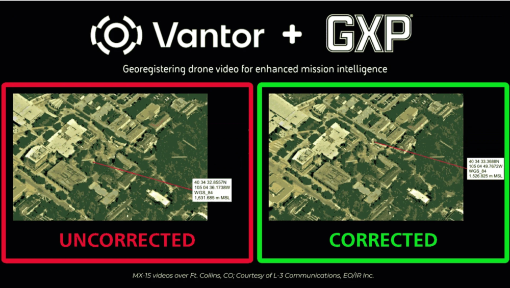
BAE Systems Geospatial eXploitation Products (GXP) and Vantor will be providing advanced intelligence and targeting capabilities for contested electronic warfare environments.
The delivery integrates part of Vantor’s Raptor, a vision-based software suite that enables autonomous systems to navigate, orient and extract accurate ground coordinates without relying on GNSS, with the GXP software ecosystem, ensuring intelligence continuity when sensors are degraded.
In modern conflict zones, the proliferation of inexpensive unmanned aerial systems (UAS) with equally low-quality sensors, in addition to widespread GPS spoofing and jamming, have rendered traditional drone video collection unreliable. Significant metadata drift in tactical video feeds leads to “targeting paralysis”: high-quality imagery is available, but the underlying geographic coordinates are too inaccurate for precision activities.
To solve this, Raptor Sync georegisters the full-motion video feed from the drone’s on-board camera with Vantor’s 3D terrain data in real time, enabling downstream GXP intelligence fusion, multi-domain interoperability across different sensors, and accurate ground coordinate extraction at a demonstrated absolute accuracy of <3 m. The system enables previously impossible intelligence and targeting workflows.
“In contested environments, the sensor’s imagery and video collections are only half the battle; the accuracy of the data it produces is what determines mission success,” said Kurt de Venecia, senior director of Product Development at BAE Systems GXP. “By including Raptor directly into our GXP intelligence workflows, we are providing analysts with the ability to maintain absolute targeting confidence, even when the platform’s systems or inertial sensors lack high absolute accuracy.”
Injecting corrected key-length-value (KLV) metadata from Raptor directly into the drone’s video stream at the edge enhances accuracy prior to exploitation in GXP software. This overrides inaccurate telemetry, enabling analysts using GXP solutions to extract weapon-quality coordinates and execute intelligence and targeting missions in real time.
“Analysts cannot afford to lose confidence in where a target actually is,” said Paul Millhouse, senior director ofRaptor Products at Vantor. “By using Raptor to correct video before it enters the GXP Ecosystem, we’re enhancing the performance of existing and new drone fleets. The result is a more resilient workflow for extracting accurate ground coordinates and maintaining operational tempo.”
These capabilities will be highlighted at GXP360° Professional Exchange & Workshop in San Diego, California (May 18-20).
U-blox has expanded its automotive GNSS portfolio with the launch of two highly specialized modules: the ZED-X20K and the ZED-A20K. This dual release addresses engineering needs of both mass-market advanced driver assistance systems (ADAS) and safety-critical autonomous architectures.
Both modules feature pin-to-pin compatibility, enabling platform flexibility and simplifying product development across vehicle generations as well as jamming and spoofing detection to mitigate the impact of security risks.
The ZED-X20K is designed for mass-market ADAS L3 and TCU/IVI applications, delivering lane-level accuracy worldwide using all-band GNSS and native Galileo High Accuracy Service (HAS). By eliminating the need for paid correction services, backend infrastructure, or service management, it reduces total cost and accelerates time-to-market while maintaining consistent global performance.
For applications that require a functional-safety concept for GNSS sensors, the ZED-A20K introduces a new architectural approach. It provides ISO 26262 ASIL-B(D)-compliant GNSS RAW data simultaneously to high-performance QM positioning outputs within a single module. This enables OEMs to transition from traditional dual hardware based-GNSS systems to a single module approach, reducing system complexity and cost.
With flexible support of externally hosted positioning engines, especially for ADAS of Levels 3 and up, the A20 concept enables enhanced flexibility for SDV–based architectures. The form-factor compatibility between ZED-X20K and ZED-A20K allows the flexibility to equip different trim levels with or without functional safety requirements out of a single socket.
The ZED-X20K has reached the engineering sample stage, and its evaluation kit is available. Samples for the ZED-A20K will be available starting in August.