In a move to enhance maritime security and operational safety, global maritime organization have released on May 20 new guidance for ships transiting the Strait of Hormuz, reports Shipping Telegraph.
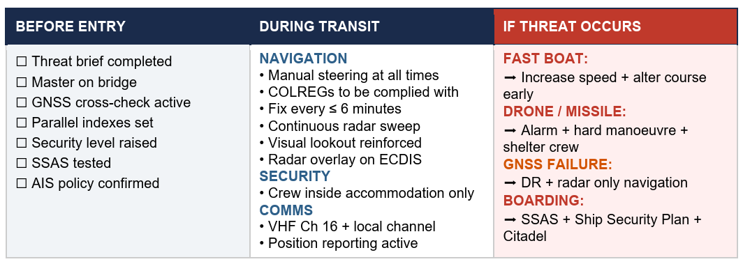
The 22-page guidance document — “Industry Guidance on the Safe Management of Vessel Transit through the Strait of Hormuz” — aims to assist in planning and safely managing vessel transits into, within or out of the Gulf region during periods of heightened regional security risk.
Thedocument was issued jointly by major industry organisations including International Chamber of Shipping (ICS), BIMCO, Intercargo, Intertanko, IMCA and OCIMF
Vessels may face a high workload and high-stress operating environment, including GNSS jamming or spoofing.
TrustPoint has been awarded a $4 million Tactical Funding Increase (TACFI) contract to demonstrate a GPS-independent positioning, navigation and timing (PNT) system.
The award was issued by SpaceWERX, the innovation arm of the United States Space Force, and jointly funded by the Small Business Innovation Research (SBIR) program and the Commercial Space Office (COMSO). It supports a full end-to-end demonstration of TrustPoint’s resilient navigation architecture designed for defense and commercial applications.
Under the contract, TrustPoint will design, deploy and operate a fully integrated PNT system comprising four satellites and four ground stations, delivering a complete operational architecture. The program will execute an end-to-end system demonstration, including live trilateration across multiple space and ground assets, operational services and advanced receivers.
With an accelerated execution timeline, initial system deployments will occur within 12 months, establishing a rapid deployment model designed to scale to significantly larger constellations while prioritizing affordability, operational relevance, and capital efficiency.
“We founded TrustPoint on the belief that resilient navigation does not require billion-dollar constellations,” said Patrick Shannon, founder and CEO of TrustPoint. “This program will prove our technology’s GPS independence while demonstrating that real, operational PNT capability can be delivered with exceptional capital efficiency.”
Beyond GPS-independent C-band demonstrations, the system will validate a software-defined architecture that supports on-demand reconfiguration of navigation services in contested, degraded and denied environments, pioneering commercial delivery of this capability. TrustPoint’s experience includes the first C-band GNSS signal transmission with real-time reception and the first broadcast-based ground-to-space C-band PNT demonstration.
The program directly advances national security objectives. It also establishes a scalable foundation for future commercial services, redefining what is possible for users who require reliable PNT in GPS-challenged environments.
Norwegian insurer DNK will provide members with assured positioning, navigation and timing (A-PNT) services using Iridium Communications’ low-Earth orbit satellite network. DNK, Den Norske Krigsforsikring for Skib, specializes in war-risk insurance.
The new program allows its clients to select systems from specialized technology vendors to protect against GNSS interference while qualifying for insurance premium rebates.
The framework aligns with DNK’s aim of using digital technologies to safeguard Norwegian-owned or controlled vessels from war, terror, piracy and cyberattacks.
“Over the past five years, we have seen a sharp increase in GNSS interference, especially in the Black Sea, the Baltic Sea and more recently, in the Persian Gulf and Red Sea,” said Svein Ringbakken, CEO at DNK.
“GNSS signal interference can not only increase the risk of collision or grounding but also compromise critical safety systems. This program offers our members the opportunity to lower premiums by investing in cost-effective A-PNT solutions to maintain situational awareness, safety and positioning integrity.
“This program will not only help members lower premiums and ensure the safety of their vessels but help us collect data we can share with owners, managers and other stakeholders operating in known and emerging conflict zones.”
DNK evaluated alternative positioning frameworks based on Iridium’s global network of 66 low-Earth orbit (LEO) satellites. The vendors participating in the program offer subscription-based hardware systems with a configuration including an Above Deck Unit that transmits jamming and spoofing telemetry back to DNK, alongside an optional Below Deck Unit that provides real-time situational awareness directly to the vessel crew.
“GNSS jamming and spoofing not only compromise situational awareness, the intentional manipulation of positioning data can also lead vessels into sanctioned or restricted zones,” said Alan Belardinelli, Project Manager at DNK. “After extensive research, DNK found that the Iridium signal, which is 1,000 times more powerful than GNSS signals, is significantly more difficult to disrupt, adding a significant layer of enhanced positioning resilience. Signal attacks can also play havoc with onboard digital systems that rely on GNSS to provide a source of timing, necessary for safe navigation and efficient operations.”
The project has received formal support from Norwegian authorities, represented by Marianne Sivertsen Næss, Minister of Fisheries and Ocean Policy, alongside the Norwegian Shipowners’ Association, represented by Knut Arild Hareide, Chief Executive Officer.
“PNT Iridium stands as a powerful and effective complement to GNSS, ensuring continuity for vessels when traditional signals are degraded or denied,” said Rohit Braggs, vice president of PNT at Iridium. “More importantly, it acts as a resilient ‘source of truth’ by providing assured timing and positioning that maritime systems can depend on, whether in open waters or bustling ports.”
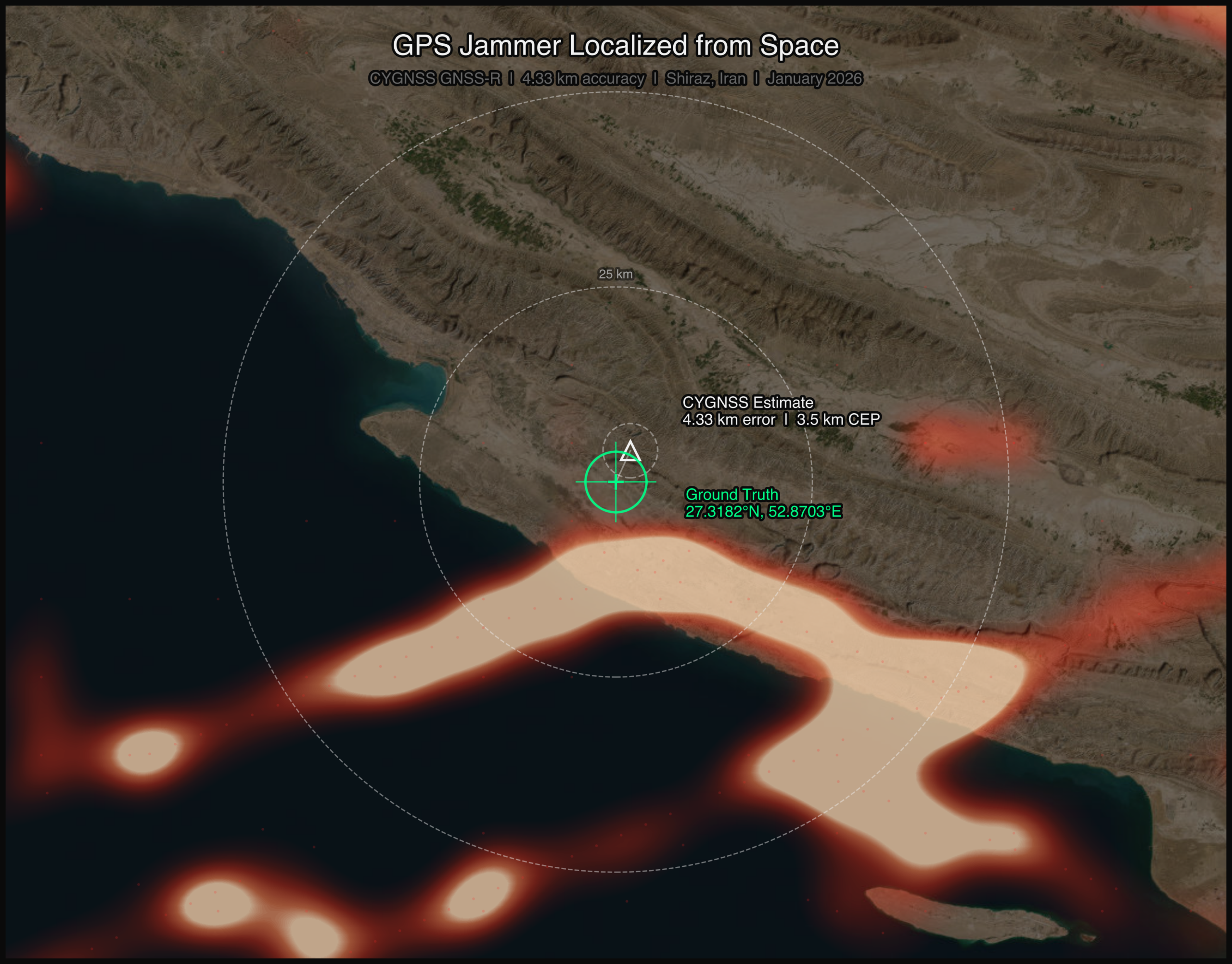
On a January morning in 2026, a GPS jammer powered up near Shiraz, Iran. It was not the first, and it would not be the last. The Strait of Hormuz corridor has become one of the most persistently jammed airspaces on Earth. But this time, two satellites were watching from very different vantage points, and together they would demonstrate something new: that spaceborne sensors can localize a terrestrial GPS jammer to within a few kilometers, using physics alone.
This article presents the first direct comparison of Cyclone Global Navigation Satellite System (CYGNSS) — a NASA GNSS reflectometry constellation — and NASA-ISRO Synthetic Aperture Radar (NISAR) — an L-band synthetic aperture radar for GPS jammer localization. The results challenge assumptions about which modality performs better and reveal that the answer depends on a question most analysts forget to ask.
The setup: Known jammer, known position
Validation requires ground truth. With help from the PNT community, we identified a GPS jammer operating near 27.32°N, 52.87°E (approximately 50 km southwest of Shiraz) that was active on Jan. 8 and Jan. 20, 2026, with confirmed quiet periods on Dec. 15 and Dec. 27, 2025. The jammer’s position was established through independent signals intelligence.
This gave us a controlled experiment: two “jammer ON” dates and two “jammer OFF” baseline dates, with satellite coverage from both CYGNSS and NISAR spanning the full period.
Two satellites, two physics
CYGNSS is a constellation of eight microsatellites that measure GPS signals reflected off Earth’s surface. Each spacecraft carries a delay-Doppler receiver that maps reflected signal power across a grid of delay and Doppler bins, known as the delay-Doppler map, or DDM. When a terrestrial jammer is active, it floods the GPS band with noise, elevating the DDM noise floor and suppressing the coherent surface reflection. The effect is detectable hundreds of kilometers from the jammer, creating a wide-area footprint in the reflected signal data.
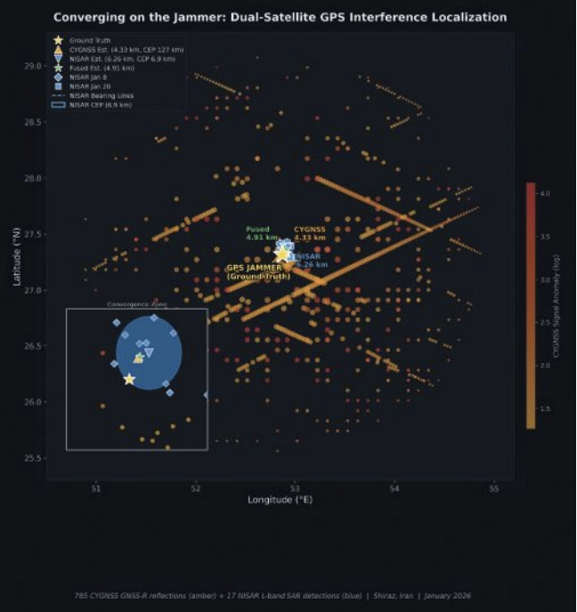
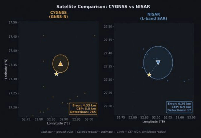
FIGURE 1 Jammer localization tracks from both CYGNSS and NISAR satellite constellations. (All figures by Sean Gorman)
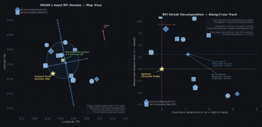
NISAR operates an L-band SAR at 1.257 GHz, just 30 MHz from the GPS L2 frequency at 1.2276 GHz. When a GPS jammer’s broadband emissions leak into NISAR’s receive band, they create characteristic streaks in the SAR imagery. The streaks are elongated in the cross-track (range) direction, not along-track, a counterintuitive result that follows directly from SAR signal processing. In azimuth (along-track), the jammer is a fixed-point source with a valid Doppler history, so the SAR azimuth processor focuses it correctly, similar to any ground target. But in range (cross-track), the jammer’s broadband noise does not match the SAR’s chirp waveform, so range compression smears the energy across many range bins rather than compressing to a point. The result is a streak perpendicular to the flight direction, whose along-track centroid encodes the jammer’s latitude and whose cross-track extent encodes a range arc, which is the distance from the orbit ground track (FIGURE 1). The bearing of each streak encodes the jammer’s direction relative to the satellite’s ground track.
FIGURE 2 Crosstrack visualization for NISAR RFI streaks.
The two sensors could hardly be more different. CYGNSS sees the jammer’s effect on reflected GPS signals, offering an indirect measurement spread across hundreds of specular reflection points. NISAR sees the jammer’s emissions directly in its own receiver, which is a more precise measurement, but only along the satellite’s narrow ground track. FIGURE 2 shows both detection sets converging on the jammer location.
CYGNSS: 785 Detections, 4.33 km Error
We processed all CYGNSS Level 1 data within 200 km of the jammer location on both ON and OFF dates. Four detection methods contributed observations:
■ DDM noise floor (419 detections): The pre-computed ddm_noise_floor variable, calibrated against the thermal noise reference, proved the strongest discriminator. Near-jammer values exceeded 15,000 counts against a ~10,000 mean background.
■ Spatial noise grid (299):A 10 km gridded analysis identified cells with anomalously elevated noise relative to adjacent cells.
■ SNR hole detection (66): Coherent surface reflections were suppressed near the jammer, creating spatial “holes” in the SNR field.
■ NBRCS drop (1): Surface reflectivity dropped approximately 16% near the jammer, though this method produced few threshold exceedances.
Across four DDM channels per spacecraft and multiple passes, this yielded 785 total anomalous observations on the jammer-ON dates.
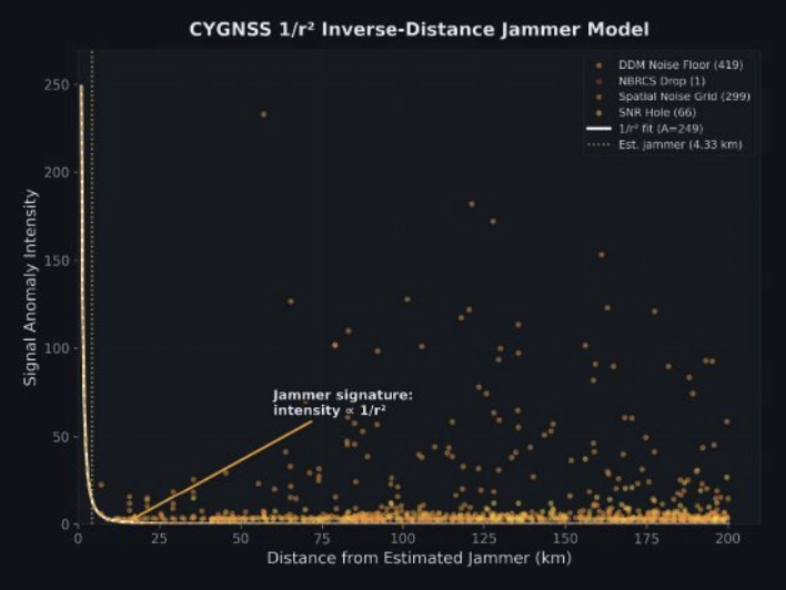
FIGURE 3 Scatterplot of interference insensity versus distance for CYGNSS.
Localizing using a simple centroid of all 785 detection positions placed the jammer 32.1 km from truth, with too many distant, low-SNR detections diluting the estimate.
Instead, we fit a parametric 1/r² inverse-distance model:
I(r)=Ar2
where A is a free amplitude parameter and r is the distance from a candidate jammer position. We jointly optimized the jammer position and amplitude using SciPy’s Nelder-Mead optimizer across all 785 observations, weighted by intensity. The optimizer converged on a position 4.33 km from ground truth, providing a 27.7 km improvement over the centroid (FIGURE 3).
The baseline: Zero false positives
On the jammer-OFF dates (Dec. 15 and Dec. 27, 2025), the pipeline produced exactly zero detections using the same thresholds, geographic area and satellites: a completely clean result. This suggests that the 785 detections are unlikely to be sensor artifacts or geographic anomalies. They disappear when the jammer turns off.
NISAR: 17 Detections, 6.26 km Error
NISAR’s approach is fundamentally different. Rather than measuring hundreds of reflected signals across a wide area, it captures direct emissions in a narrow swath, but with far greater geometric precision.
We processed NISAR L2 GCOV (geocoded covariance) products from Track 157, Frame 15 (ascending) for three dates: the Dec. 27 baseline and the Jan. 8 and Jan. 20 jammer-ON passes. The detection pipeline used eigenvalue decomposition of the polarimetric covariance matrix:
λ₁ ratio thresholding: In jammer-contaminated pixels, the dominant eigenvalue λ₁ of the 2×2 [HH, HV] covariance matrix rises sharply relative to the scene mean, indicating an unpolarized additive source.
Cross-polarization ratio (HV/HH): GPS jammer emissions are unpolarized, disproportionately elevating the HV channel. Anomalous HV/HH ratios flag contaminated azimuth lines.
Iterative outlier trimming: Three rounds of 1.5σ clipping removed scattered false detections, leaving 17 high-confidence streak centroids.
FIGURE 4 Error and CEP Metrics Comparison for CYGNSS and NISAR.
With detections from two passes on different dates, we had two independent bearing lines. Each pass’s streak centroids defined an azimuth aligned cluster whose major axis pointed toward the jammer. A PCA fit to the two clusters extracted the bearing: 308.1° from the Jan. 8 pass and 316.2° from Jan. 20. Their intersection — computed via scipy optimization of the angular residual — landed 6.26 km from ground truth (FIGURE 4).
The along-track/cross-track decomposition reveals why the 6.26 km error is a geometric ceiling for this dataset, not a processing limitation. Both passes come from the same Track 157 ascending orbit on a 12-day repeat cycle. The intensity-weighted along-track centroids land at +3.0 km and +3.1 km north of the jammer, a direct stable latitude measurement. The cross-track centroids land at +5.4 km and +5.6 km east of the orbit ground track, a range measurement. But because both passes share identical orbit geometry, the two range arcs are nearly parallel. The bearing difference between passes (308.1° vs 316.2°) is only 8.1°, producing a shallow intersection angle and poor cross-range resolution. A single descending pass, which would cross the ascending track at approximately 60-70°, would transform the geometry from two near-parallel lines to a genuine triangulation, potentially reducing the localization error to sub-2 km. Unfortunately, no descending NISAR pass covering this jammer site was available in the beta archive, which ends on Jan. 20, 2026.
The CEP (circular error probable, the radius containing 50% of repeated estimates) was 6.88 km, meaning if we ran this analysis on many similar jammers, half our estimates would fall within ~7 km.
Who wins?
CYGNSS wins, and not just on accuracy.
A naive confidence metric for the 1/r² fit would be the scatter of the 785 input detections (CEP = 127 km). But the detections are not the estimate; they are the inputs to a model fit. The relevant confidence question is: How stable is the fitted position?
We answered this with a 500-iteration bootstrap: resample the 785 detections with replacement, re-run the 1/r² optimizer each time and measure the spread of the resulting position estimates. The bootstrap CEP, the median radial distance across 500 fitted positions, was 3.48 km. The optimizer converges stably to within a few kilometers of the same location regardless of which detections are included.
This means CYGNSS achieves 4.33 km error with 3.48 km confidence, both better than NISAR’s 6.26 km error and 6.88 km confidence.
The bootstrap CEP also reveals what the raw scatter obscures: the 1/r² fit is constrained primarily by the ~80 high-intensity detections within 30 km of the jammer. The remaining 700 distant, low-intensity detections contribute little to the position estimate — they are correctly downweighted by the intensity-weighted least squares. The fit’s stability comes from the physics: a 1/r² signal has steep gradients near the source, providing strong positional constraints where it matters most.
Bayesian fusion: Can we get both?
The obvious next question: Can we combine CYGNSS’s wide-area sensitivity with NISAR’s geometric precision? We implemented four fusion strategies, all designed to work without ground truth:
■ Bayesian Gaussian posterior: Model each sensor’s estimate as a 2D isotropic Gaussian with σ = CEP/1.1774. The posterior is the product of the two Gaussians: an analytical precision-weighted mean.
■ NISAR-prior constrained 1/r²: Re-run the CYGNSS optimizer with a Gaussian regularization term pulling toward the NISAR estimate, sweeping the regularization weight λ from 0.01 to 10.
■ NISAR-proximity re-weighted 1/r²: Apply a Gaussian kernel centered on the NISAR estimate to the CYGNSS detections before fitting, effectively upweighting observations consistent with the SAR result.
■ Joint CEP-balanced: Combine the CYGNSS gradient signal with NISAR cluster proximity, weighted by (σ_CYGNSS/σ_NISAR)².
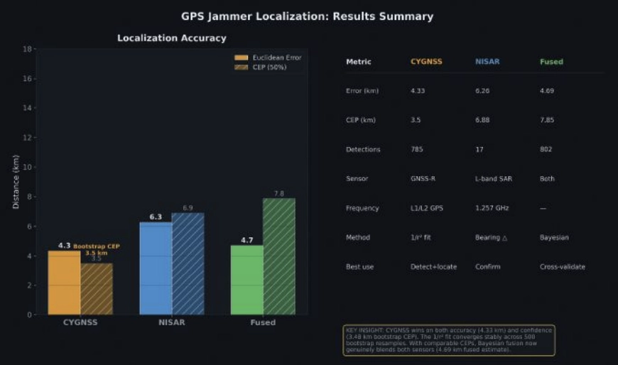
FIGURE 5 Summary statistics for jammer localization with CYGNSS, NISAR and fused approach.
With the bootstrap CEP, the precision ratio flips. The CYGNSS Gaussian (σ = 2.95 km) is now 2× tighter than NISAR (σ = 5.84 km). The Bayesian posterior, the precision-weighted mean, lands at 4.69 km, pulling toward CYGNSS’s better estimate while incorporating NISAR’s independent geometric constraint. FIGURE 5 shows the fusion: two comparable Gaussians whose product is tighter than either alone.
The fused result (4.69 km error, 7.85 km CEP) is not quite as accurate as CYGNSS alone (4.33 km), because NISAR’s 6.26 km estimate pulls it slightly away from truth. But operationally, the fusion provides a cross-validated answer: two independent physics arriving at similar locations builds confidence that neither sensor is producing an artifact.
The key insight is that the bootstrap CEP unlocked meaningful fusion. When the raw scatter CEP (127 km) was used, NISAR dominated the posterior 343:1 and fusion added nothing. With the fit-based CEP (3.48 km), both sensors contribute, and the posterior reflects genuine multi-modal evidence.
Operational implications
For CYGNSS: CYGNSS excels at both detection and localization. Its 785 detections across a 200 km radius, with zero false positives on baseline dates, provide unambiguous jammer detection. The 1/r² fit achieves 4.33 km accuracy with a bootstrap-verified 3.48 km CEP, meaning an analyst can trust the result to single-digit kilometer precision without ground truth. CYGNSS’s eight-satellite constellation also provides sub-daily revisit, enabling near-real-time monitoring.
For NISAR: NISAR provides independent geometric confirmation. With just two passes over an active jammer, the bearing intersection achieved 6.26 km accuracy with a 6.88 km CEP. The 6.26 km result is constrained by orbit geometry, not by detection sensitivity. Our two ascending passes from Track 157 produced nearly parallel range arcs with only 8.1° of bearing separation. Adding a single descending pass would provide a crossing angle of 60° to 70° and could reduce localization error to sub-2 km — transforming NISAR from a confirming sensor into a precision localization tool in its own right. The limitation in this study was data availability: The NISAR beta archive contained only ascending Track 157 passes over the jammer site. NISAR’s 12-day repeat cycle and fixed ground track also mean the jammer must be active when the satellite passes overhead. NISAR’s current value is as a confirming sensor — when both modalities converge on the same location, confidence increases beyond what either achieves alone.
For Fusion: With comparable CEPs (3.48 km vs 6.88 km), fusion now produces genuinely blended estimates. The Bayesian posterior at 4.69 km reflects real multi-sensor information. Future improvements, such as more NISAR passes with diverse bearings or CYGNSS multi-week accumulation, would tighten both estimates further.
For the Adversary: These results demonstrate that GPS jammers operating in contested airspace are observable and localizable from orbit using openly available civilian satellite data. The 4.33 km CYGNSS result is approximately 2× better than the published state of the art for GNSS-R jammer localization (~9 km grid resolution, Chew et al., 2023) and the NISAR bearing intersection approach has not been previously demonstrated for jammer geolocation.
Still broadcasting: Jammer persistence through conflict
The validation analysis used January 2026 data. But on Feb. 28, armed conflict erupted in the region. Did the jammer survive?
We ran the CYGNSS noise floor detection pipeline for each day from Feb. 28 through April 6, comparing against the December 2025 baseline. The answer is unambiguous: The jammer is not only still active — it is operating at dramatically higher power.
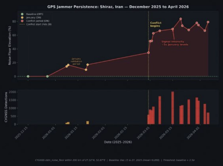
FIGURE 6 A timeline of jammer activity for Shiraz, Iran, from December 2025 to April 2026.
In January, the jammer elevated the CYGNSS noise floor by approximately 15% above baseline. By early March, days after the conflict began, noise elevation had jumped to 50% to 60%. By mid-March, it reached 70% to 84%, where it remained through early April. Detection counts tell the same story: 89 to 192 per day in January, rising to 1,000 to 2,000 per day during the conflict (FIGURE 6).
The escalation was immediate. On Feb. 28, noise elevation was +34.5%, already double the January level. By March 3, it had reached +62.7%, and by April 6, it peaked at +79.1%. The signal has remained at 5× the January intensity through the most recent available data (April 6, 2026).
Several interpretations are consistent with this pattern:
■ Power increase: The operator increased jammer output power, perhaps in response to the conflict or as a defensive posture against GPS-guided munitions.
■ Additional jammers: Multiple units may have been co-located or deployed nearby, creating an aggregate signature larger than any single device.
■ Duty cycle change: The jammer may have shifted from intermittent to continuous operation.
What is clear is that the jammer we localized in January was not incapacitated by the conflict. It was amplified. CYGNSS’s sub-daily revisit capability makes this kind of persistent monitoring possible using entirely passive, civilian satellite data — no tasking, no cooperation with the target state and no risk to reconnaissance assets.
Context and prior work
CYGNSS-based RFI detection builds on work by Chew et al., 2023, who demonstrated grid-level jammer detection at approximately 9 km resolution using DDM noise floor anomalies. Our 1/r² parametric fit extends this from detection to localization, achieving sub-5 km accuracy by exploiting the physics of signal power decay.
At the other end of the precision spectrum, Murrian et al., 2021, demonstrated ~220 m jammer localization using ISS-mounted Doppler measurements of raw intermediate-frequency (IF) data. This approach achieves an order of magnitude better precision than our methods but requires specialized hardware and raw signal access not available on current operational satellites.
The NISAR bearing intersection approach demonstrated here is, to our knowledge, the first published use of L-band SAR RFI streaks for jammer triangulation. The key insight is that NISAR’s proximity to GPS L2 (just 30 MHz separation) makes it an unintentional but effective GPS interference sensor.
Summary
Two satellites, two physics, one jammer. CYGNSS sees the interference footprint across hundreds of kilometers and localizes the source through inverse-distance physics. NISAR sees the emissions directly in its SAR receiver and triangulates through bearing intersection. Both achieve sub-7 km accuracy independently; together, they cross-validate and build the confidence that operational use demands.
The jammer near Shiraz is still there — louder than ever. The satellites are still watching.
Chew, C., Shah, R., Zuffada, C., et al. (2023). “Demonstrating CYGNSS as a Tool for Detecting GNSS Interference on a Global Scale.” IEEE Journal of Selected Topics in Applied Earth Observations and Remote Sensing.
Murrian, M.J., Narula, L., Iannucci, P.A., et al. (2021). “GNSS Interference Monitoring from Low Earth Orbit.” Navigation: Journal of the Institute of Navigation, 68(1).
NASA JPL. (2024). “NISAR L-band SAR Technical Specifications.” NASA/ ISRO SAR Mission Documentation. Closas, P., Fernández-Prades, C. (2023). “GNSS Interference Detection and Mitigation: A Survey.” Signal Processing, 206.
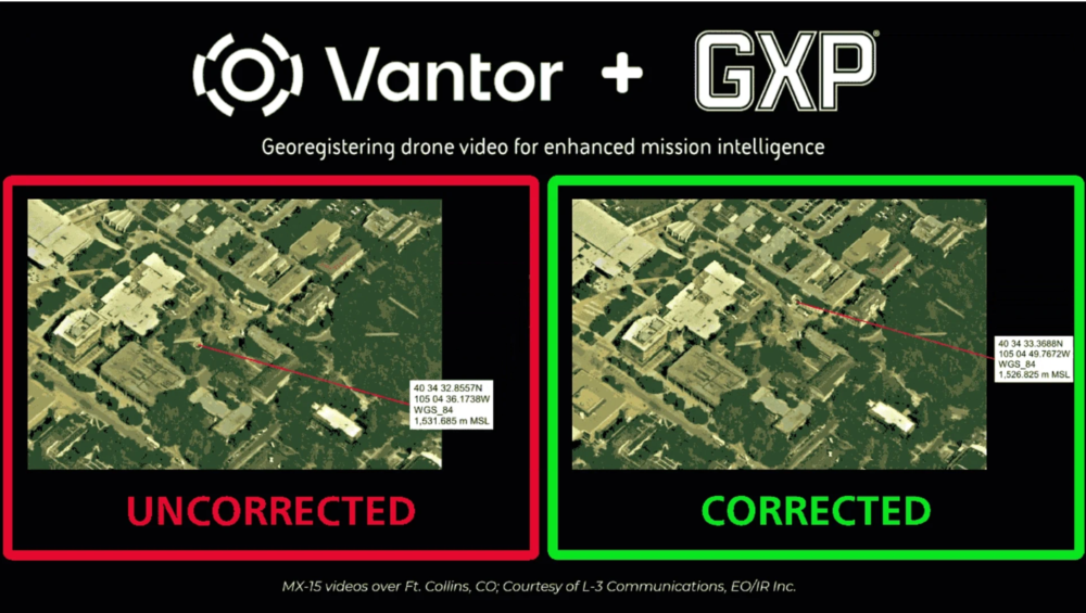
BAE Systems Geospatial eXploitation Products (GXP) and Vantor will be providing advanced intelligence and targeting capabilities for contested electronic warfare environments.
The delivery integrates part of Vantor’s Raptor, a vision-based software suite that enables autonomous systems to navigate, orient and extract accurate ground coordinates without relying on GNSS, with the GXP software ecosystem, ensuring intelligence continuity when sensors are degraded.
In modern conflict zones, the proliferation of inexpensive unmanned aerial systems (UAS) with equally low-quality sensors, in addition to widespread GPS spoofing and jamming, have rendered traditional drone video collection unreliable. Significant metadata drift in tactical video feeds leads to “targeting paralysis”: high-quality imagery is available, but the underlying geographic coordinates are too inaccurate for precision activities.
To solve this, Raptor Sync georegisters the full-motion video feed from the drone’s on-board camera with Vantor’s 3D terrain data in real time, enabling downstream GXP intelligence fusion, multi-domain interoperability across different sensors, and accurate ground coordinate extraction at a demonstrated absolute accuracy of <3 m. The system enables previously impossible intelligence and targeting workflows.
“In contested environments, the sensor’s imagery and video collections are only half the battle; the accuracy of the data it produces is what determines mission success,” said Kurt de Venecia, senior director of Product Development at BAE Systems GXP. “By including Raptor directly into our GXP intelligence workflows, we are providing analysts with the ability to maintain absolute targeting confidence, even when the platform’s systems or inertial sensors lack high absolute accuracy.”
Injecting corrected key-length-value (KLV) metadata from Raptor directly into the drone’s video stream at the edge enhances accuracy prior to exploitation in GXP software. This overrides inaccurate telemetry, enabling analysts using GXP solutions to extract weapon-quality coordinates and execute intelligence and targeting missions in real time.
“Analysts cannot afford to lose confidence in where a target actually is,” said Paul Millhouse, senior director ofRaptor Products at Vantor. “By using Raptor to correct video before it enters the GXP Ecosystem, we’re enhancing the performance of existing and new drone fleets. The result is a more resilient workflow for extracting accurate ground coordinates and maintaining operational tempo.”
These capabilities will be highlighted at GXP360° Professional Exchange & Workshop in San Diego, California (May 18-20).
The new autopilot is engineered to provide reliable GNSS‑denied navigation and fully autonomous mission execution, including complex operational scenarios and seamless interoperability.
UAV Navigation — a division of Grupo Oesía specializing in advanced guidance, navigation and control solutions for unmanned vehicles — has launched the Vector-300high‑performance autopilot.
Vector-300 is designed to meet the industrial and operational requirements of mass‑produced, attritable unmanned aerial systems, with a clear focus on loitering munition and Counter-UAS (C-UAS) interceptor applications.
Vector‑300 has been engineered to combine advanced autonomous guidance, navigation and control (GNC) capabilities with scalability and manufacturability. Its architecture is designed to reduce technical complexity and enable agile, large‑scale production while ensuring consistent and reliable performance across high‑volume deployments.
Designed for high‑dynamic interception and terminal missions, Vector‑300 delivers strike‑to‑target precision guidance with bull’s eye accuracy. The autopilot supports the integration of AI‑based target identification and optical data directly into its autonomous GNC loops, enabling advanced engagement of both static and dynamic targets. This architecture supports real‑time trajectory adaptation during pursuit and terminal engagement phases, making Vector‑300 suitable for demanding loitering munition and C-UAS interceptor operations.
Vector‑300 is designed to operate in highly contested and GNSS‑denied environments, even under electronic warfare (EW) jamming, spoofing and meaconing. Its robust navigation core relies on advanced inertial algorithms and multisensor fusion to ensure mission continuity across all phases of operation and can be easily complemented with UAV Navigation–Grupo Oesía proprietary solutions such as the Visual Navigation System to enhance dead‑reckoning accuracy.
Building on the battlefield-proven capabilities of the Vectorautopilot family, Vector‑300 enables the full range of advanced operations already established across UAV Navigation–Grupo Oesía solutions. These include
fully autonomous mission execution
swarming and formation flight
4D trajectory management to reach targets at a predefined time
high‑dynamic maneuvers
manned‑unmanned teaming (MUT) operations
many other advanced autonomous capabilities.
Its open and modular architecture is designed to ensure interoperability with third‑party platforms, payloads and sensors through seamless integration with Vector‑MCC. This architecture also enables the integration of autonomous decision‑making software, allowing platforms equipped with Vector‑300 to adapt to evolving concepts of operation and advanced autonomy requirements.
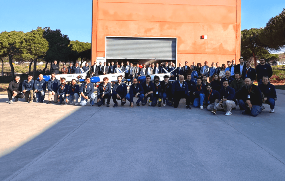
The UAV Navigation–Grupo Oesía flight control system, as a subcontractor to SATNUS, proved key to the success of the demonstration.
In March, the Spanish consortium SATNUS successfully completed the fourth flight demonstration campaign under Pillar 3 of the Next Generation Weapon System / Future Combat Air System (NGWS/FCAS) program, held at the INTA‑CEDEA facilities. The campaign comprised a total of nine flights aimed at verifying the flight control software dedicated to collaborative manned‑unmanned teaming (MUT) operations, led by SATNUS and developed in cooperation with international partners Airbus GmbH and MBDA, and integrated into the Next Generation Autonomy Computer (NGAC). During these tests, the remote carriers were represented by both real and simulated platforms of the manned‑unmanned teaming & common systems demonstrator (MCSD).
During the campaign, key MUT functionalities were demonstrated, including formation flight, evasive maneuvers, collaborative navigation, mission replanning and formation breakup, among other capabilities. Flights involved up to three real Remote Carriers operating simultaneously, supported by UAV Navigation–Grupo Oesía’s technological contribution in guidance, navigation and control (GNC) systems, which acted as a key enabler for the safe execution of the flight maneuvers carried out within the objectives defined by SATNUS under Pillar 3 of the NGWS/FCAS program.
The campaign concluded with the execution of flights 29, 30, and 31, in the presence of the Combined Project Team (CPT) and representatives from the National Program Offices of the three participating nations: Spain, France and Germany.
Engineering teams from all SATNUS partner companies, including members from UAV Navigation–Grupo Oesía, carried out highly specialized work to achieve this milestone, successfully meeting all established objectives. In this context, UAV Navigation–Grupo Oesía’s contribution supported the proper execution of operations and helped validate the capabilities demonstrated throughout the campaign.
SATNUS has expressed its appreciation for the support and trust of the Spanish Armed Forces and the Spanish Ministry of Defence throughout the entire process and will continue advancing the development of capabilities within other NGWS/FCAS-related programs.
The U.S. Federal Aviation Administration (FAA) has issued a proposed rule that would allow specific categories of critical infrastructure sites to apply for restrictions on drone operations around their facilities.
The restrictions would be submitted and approved via a new FAA web portal. Approval will be based on safety or security criteria. Sixteen sectors would be eligible for restrictions including energy production, transportation systems, chemical facilities, water treatment plants, and defense industrial complexes.
The rule would establish two types of restrictions:
Standard Unmanned Aircraft Flight Restriction (UAFR): A general restriction that bars unmanned aircraft operations within a specific boundary, except for operators who have previously met rigorous safety and security standards.
Special Unmanned Aircraft Flight Restriction (UAF): A much more severe restriction that bars unmanned aircraft operations within a specific boundary for all operators unless they have the express prior approval from both the FAA and the sponsoring agency (for example, the Department of Homeland Security).
The restricted area would have clearly defined horizontal and vertical boundaries. Violators could face civil or criminal penalties.
The rule would also allow site operator to contact law enforcement if a drone flew in a restricted area, after which authorities can use Remote ID to locate the control station or operator. Pilots could face license suspensions, revocations, fines and criminal charges for entering these no fly zones.
Drone operators are encouraged to check B4UFLY for the latest breakdown on where pilots can and cannot fly.
Additional Information:
Restriction criteria includes impacts to aviation safety, protecting people and property on the ground, national security, or homeland security.
The full list of eligible site categories are:
Chemical
Commercial
Communications
Critical manufacturing
Dams
Defense industrial base
Emergency services
Energy
Financial services
Food and agriculture
Government services and facilities
Healthcare and public health
Information technology
Nuclear reactors, materials, and waste
Transportation systems
Water and wastewater
The comment period on the proposed rule will run until July 5, 2026.
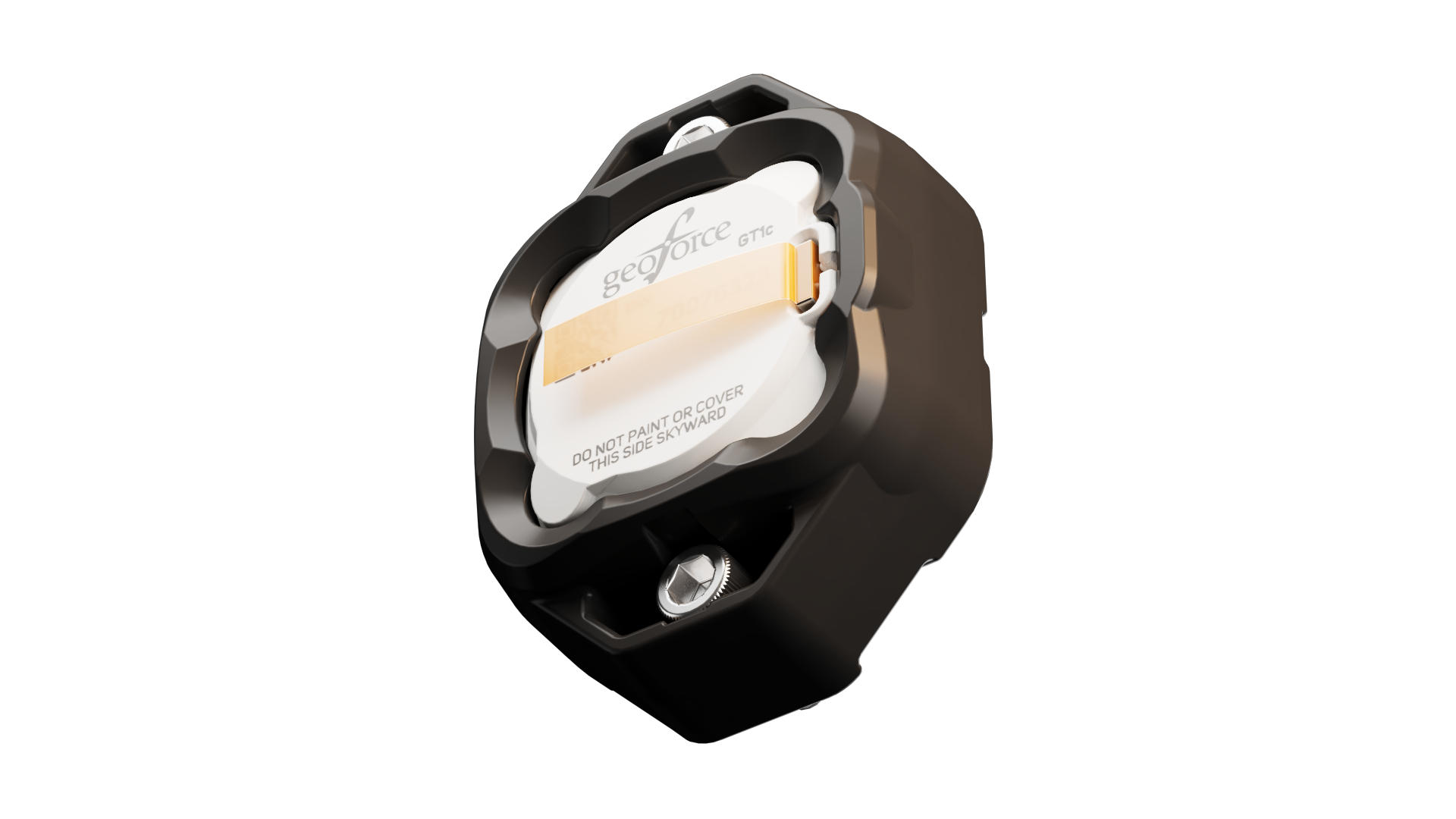
Geoforce has launched the GT1c, which enables rugged cellular equipment tracking at scale. According to Geoforce, the GT1c has a more cost-effective, purpose-built design to complement Geoforce’s full range of satellite tracking devices.
The GT1c operates on AT&T’s network, built for the next era of IoT connectivity for business. The device’s launch builds on a collaboration with AT&T Business announced in March and represents the first product outcome of the relationship.
The GT1c captures and feeds smart location updates to Geoforce’s mobile-enabled asset intelligence platform, providing field operations and asset managers with visibility into the location, movement and utilization of industrial assets and equipment.
The GT1c has an encapsulated design, reinforced bezel, and intrinsic safety certification to ensure that it can survive in hazardous, heavy-vibration environments and extreme temperature ranges. It’s low price means customers can afford to track almost every asset class, the company said.
Pilot programdemonstrates value
In a pilot program with Black Diamond Equipment Rental, the GT1c demonstrated that expanding tracking across mid-tier and small assets is both practical and operationally impactful. The heavy-duty equipment rental company expanded tracked inventory by 26% across smaller and mid-tier construction and oil and gas rental assets. The result was a significant reduction in operational friction and time savings expected to exceed 500 hours per year.
The GPS Next Generation Operational Control System program of the U.S. Space Force has been cancelled by the Defense Acquisition Executive, based upon the recommendation of the acting service acquisition executive.
OCX was intended to update command and control of the GPS satellite constellation, replacing the current system, known as the Architecture Evolution Plan (AEP), as well as replacing the Launch, Anomaly and Disposal Operations system. However, the program was unable to deliver needed capabilities on an operationally relevant timeline at an acceptable level of risk to meet the GPS constellation modernization needs.
“It’s important we refine and update acquisition processes to prioritize rapid, incremental capability delivery versus complex ‘all or nothing’ system deliveries,” said Acting Service Acquisition Executive Tom Ainsworth. “The Department of War [Defense] has made clear that we need to deliver warfighting capability at a faster rate. We must continue to work with industry to meet the needs of our warfighters as we focus on delivering the right technology on the right timeline to enhance our capabilities and maintain space superiority.”
In July 2025, following a multi-year regimen of factory testing, the Space Force contractually accepted OCX from RTX (Raytheon) and began extensive integrated systems testing to resolve liens carried over from factory testing, as well as to ensure the system could operate within the broader GPS enterprise of ground systems, satellites, and user equipment.
As of January 2026, the program cost was approximately $6.27 billion which included complete Raytheon funding to date and other government costs, such as the cost of government testing and support costs to the OCX acquisition program office.
“Regrettably, extensive system issues arose during the integrated testing of OCX with the broader GPS enterprise,” said Mission Delta 31 Commander Col. Stephen Hobbs. “Despite repeated collaborative approaches by the entire government and contractor team, the challenges of onboarding the system in an operationally relevant timeline proved insurmountable. We discovered problems across a broad range of capability areas that would put current GPS military and civilian capabilities at risk.”
Because of past delays on the OCX program, the Space Force has made incremental improvements over the last 10 years to AEP. These successful upgrades provide confidence that further upgrades to GPS ground systems will continue to support the enterprise and deliver new capabilities.
“Ultimately, we analyzed the work remaining on OCX and compared this with the current GPS control system capability,” Hobbs said. “The analysis revealed additional investment in OCX was no longer the best solution for protecting and advancing GPS capabilities. Instead, we will continue enhancing the current control system to operate the GPS satellite constellation.”
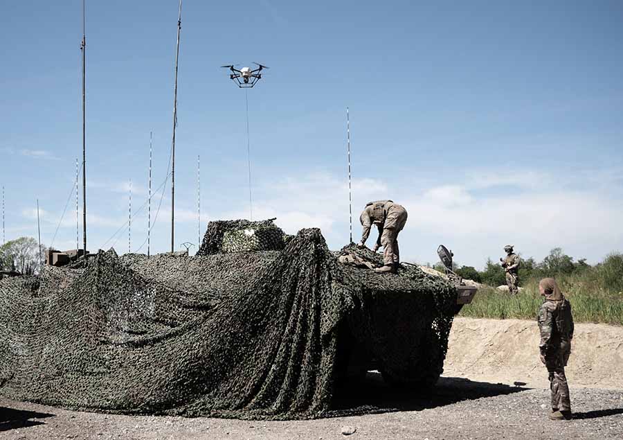
Elistair, manufacturer of tethered drones for security applications, participated in Orion 2026, France’s most ambitious joint military exercise in decades. In the exercise, Elistair contributed its Khronos automated tethered DroneBox, used for ISR and tactical communications missions.
Running from February to April, ORION 2026 mobilized up to 12,500 military personnel across the country in a high-intensity, multi-domain scenario involving land, sea, air, space, cyber and electromagnetic domains. More than 1,200 drones of all types were deployed throughout the exercise.
Elistair participated in Phase O4 (April 7–30) following its fisrt contribution during Phase O2 in February, which demonstrated France’s ability to fully integrate into a NATO command structure for collective defense scenario. During the week of April 27, forces conducted offensive exploitation operations, river crossings, retaking of key positions, and live-fire exercises.
The Khronos system
Forces need real-time situational awareness in contested and GNSS-denied environments. The Khronos system provides continuous aerial surveillance from fixed or mobile platforms. It does not depend on GNSS, radio frequency infrastructure, or battery-limited free-flying aircraft.
Khronos deploys from a transportable DroneBox in under two minutes. The system can deliver continuous day and night imagery for up to 24 hours, making it a “pocket watchtower” for tactical units.
The tethered drone operates in GPS- and RF-denied conditions through a secured tether and advanced positioning system. Elistair targets armed forces, law enforcement, civil security agencies, and private security operators in more than 70 countries. The company runs operations from France and North Carolina.
BAE Systems has entered production and started initial deliveries of its NavGuide GPS receiver, a portable, field-installable device designed to provide secure positioning, navigation and timing (PNT) for vehicle, handheld and sensor applications.
NavGuide serves as a drop-in M-code upgrade to the company’s Defense Advanced GPS Receiver (DAGR), which has concluded production after more than 20 years in service. The new receiver is backward-compatible with existing DAGR installations and is designed for rapid integration into current mounts and accessories without interrupting operations. It is available to U.S. armed forces and allied partners through foreign military sales.
“NavGuide is more than just a replacement for DAGR,” said Luke Bishop, director of navigation and sensor systems at BAE Systems. “Built on the same trusted foundation for easy installation and transition, it delivers a more resilient, user-friendly M-code GPS solution.”
NavGuide uses the military’s M-code GPS signal to enhance protection against jamming and spoofing while delivering reliable PNT in challenging environments. The compact receiver features a full-color user interface with waypoint navigation and a moving map display.
More than 650,000 DAGR units have been deployed worldwide since 2004. NavGuide maintains the same form, fit and function, while adding enhanced security and performance. BAE Systems said it has integrated NavGuide on more than 30 vehicle platforms, with installation averaging less than two minutes and requiring no changes to existing cables, mounts or vehicle software.
The company will continue to support legacy DAGR units.
BAE Systems has delivered selective availability anti-spoofing modules to more than 45 countries and has begun fielding M-code GPS receivers in multiple form factors for U.S. and allied forces.
Development and production of the company’s military GPS products take place at its engineering and manufacturing facility in Cedar Rapids, Iowa.