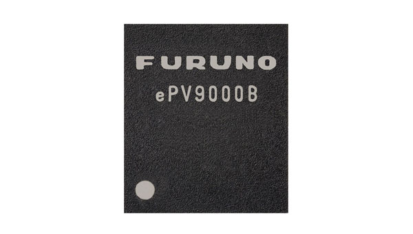
Furuno Electric Co. has released its dual-band GNSS receiver chip, eRideOPUS 9, which can achieve 50cm position accuracy without correction data.
The product is designed to provide absolute position information and can be used as a reference for lane identification, which is essential for services such as autonomous driving. It also serves as a reference for determining the final self-position through cameras, lidar and HD maps.
By using Furuno’s Extended Carrier Aiding technology, the product can achieve high-precision positioning, which eliminates the need for RTK reference stations, correction data usage and correction data reception components.
The eRideOPUS 9 supports all navigation satellite systems currently in operation, including GPS, GLONASS, Galileo, BeiDou, QZSS and NavIC. It can also receive L1 and L5 signals. The L5 band signals are transmitted at a chipping rate 10 times higher than L1 signals, which reduces the effects of multipath. The L5 signals also improve positioning accuracy in environments where radio waves are reflected or diffracted by structures, such as in urban areas.
A dual-band GNSS module incorporating eRideOPUS 9 is being jointly developed with Alps Alpine Co. and is scheduled for future release as the UMSZ6 series.
As part of our celebration of the 50th anniversary of the Global Positioning System, three long-time players in the industry share their “GPS origin story,” recent breakthroughs, and their view on the next 50 years of positioning, navigation and timing (PNT). All three began their involvement with GPS between the late 1970s and the late 1980s, before the system was completed. All three are continuously making GPS more resilient and resistant to jamming and spoofing or augmenting it with layered multi-orbit architectures of complementary PNT.
Read the origin stories, recent breakthroughs, and more insights from the following companies:
BAE Systems has more than 45 years of military GPS experience. In fact, the first ever GPS signal reception on Earth happened at one of our offices in Cedar Rapids, Iowa, on July 19, 1977, when one of our legacy companies received the signal. Since that historic day, BAE Systems’ engineers have introduced more than 50 GPS products, including GPS anti-jam and precision landing systems.
As a pioneer in military GPS technology, BAE Systems has delivered nearly two million GPS devices on more than 280 platforms around the world. We design and produce advanced GPS technology compatible with the next generation M-code signal, improving security and anti-jamming capabilities for critical defense applications.
Can you share any recent innovations from BAE Systems?
BAE Systems innovates a full portfolio of M-code-compatible military GPS solutions to meet warfighters’ needs. Our Strategic Anti-jam Beamforming Receiver — M-code (SABR-M) is the most capable integrated anti-jam (AJ) electronics GPS receiver and the first integrated AJ M-code receiver available for weapons systems. It delivers assured, global position, velocity, altitude and timing, as well as strong protection against GPS signal jamming and spoofing — critical capabilities for unmanned aerial vehicles (UAVs), precision-guided munitions (PGMs), and missiles in threat environments.
This past June, at the Joint Navigation Conference in San Diego, BAE Systems unveiled NavGuide, a next-generation Assured Positioning, Navigation and Timing (A-PNT) device featuring M-code GPS technology. It is our response to strong defense market demand for a cost-effective, high performance handheld GPS upgrade. NavGuide provides an intuitive user interface and integrates easily into platforms currently using BAE Systems’ Defense Advanced GPS Receiver (DAGR).
How is your company preparing for the next 50 years of PNT with GPS and beyond?
BAE Systems is making advancements in our critical navigation capabilities for the warfighter through the Military GPS User Equipment (MGUE) Increment 2 program. We are developing a Next-Generation Application Specific Integrated Circuit (NG ASIC) for our small form factor Miniature Serial Interface (MSI) receiver. This will enhance our full portfolio of ground, airborne and weapons M-code assured GPS receivers beyond 2030.
We have invested an enormous amount of time and energy into our facilities and simulator capabilities, especially in our state-of-the-art simulators powered by Spirent Federal signal generation and RF wavefront technology. We want to be prepared to meet the technical demands of an ever-changing threat environment, and we need to be certain our receivers are prepared for the fight the first time, every time. We put our receivers through the paces by running them through thousands of trials on our Spirent simulators to validate and verify our performance under the most demanding scenarios.
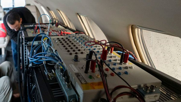
A flight test of Northrop Grumman’s airborne navigation solution, embedded GPS/INS modernization, EGI-M (Image: Northrop Grumman)
What was Northrop Grumman’s GPS Origin Story?
Northrop Grumman’s involvement with GPS has its origins during the mid-1980s, when we became an early adopter. We applied our prior decades of technical expertise in defense and commercial navigation solutions to recognize the significance of GPS as an emerging technology to optimize our inertial navigation products. The first GPS receiver was integrated with the LN-33, our main product for military aircraft, in 1987.
Around the same time, our engineers began to develop an indigenous civil GPS receiver to complement our inertial navigator for use in commercial airliners. This resulted in the certification and fielding of the LTN-2001 product, an eight channel C/A Code GPS receiver. This receiver, in concert with our Autonomous Integrity Monitored Extrapolation (AIME) algorithm, provided our customers a first-ever sole means navigation system using GPS/inertial for non-precision approach.
By the early 1990s, advancements in the semiconductor industry facilitated the reduction of the GPS receiver from a 1,000 cu in stand-alone box to a roughly 6-in by 6-in circuit card. This critical milestone allowed GPS to be embedded into an inertial navigation system (INS) without a significant increase in its size or power consumption and thereby the ubiquitous Embedded GPS INS (EGI) was born. Our first inertial navigation system with embedded military GPS capability was the LN-100G in 1991. This standard form factor was produced across the industry with installations on virtually all the front-line tactical aircraft and rotorcraft for the U.S. Department of Defense (DOD) and many of our allies.
Can you share a breakthrough?
Inspired by accomplishments in the survey community, our team conducted early location accuracy experiments to demonstrate a few decimeters of accuracy between our Woodland Hills, California, location and a facility in San Jose, California, about 500 km away. Leveraging this experience and the same signal processing, our teams became a broader solution provider for adjacent mission applications including precise formation flying for in-flight automated refueling, precision approach and landing, and decimeter-level positioning for the intelligence, surveillance and reconnaissance (ISR) community.
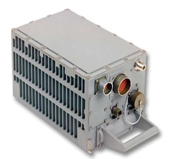
LN-100G. (Image: Northrop Grumman)
In parallel with these developments, Northrop Grumman, in partnership with the Defense Advanced Research Projects Agency (DARPA), improved the resilience of embedded GPS receivers with a more intimate coupling of INS and GPS. The DARPA GPS Guidance Package (GGP) program demonstrated a Navigation Grade Fiber Optic Gyro (FOG), greatly improved GPS tracking performance under extreme vehicle dynamics, and the ability to track at lower signal-to-noise levels. Our success on this program reinforced our reputation as a GPS integration leader and led to the introduction of Northrop Grumman’s current LN-251 product line, which is broadly used in tactical military aircraft.
In the early 2000s, Northrop Grumman initiated research into the feasibility of a Global Navigation Satellite System (GNSS) software-defined radio and started development of what we now call SERGEANT (Software Enabled Reconfigurable GNSS Embedded Architecture for Navigation and Timing). The company used Spirent signal simulators to evaluate proper GPS M-code tracking over a wide range of test cases in a controlled laboratory environment. Together with the Air Force Research Laboratory (AFRL), Northrop Grumman demonstrated advanced receiver capabilities using SERGEANT starting in 2010. In 2018, AFRL used SERGEANT for the first real-time flight demonstration of a GPS M-code SDR.
How is your company preparing for the next 50 years of PNT with GPS and beyond?
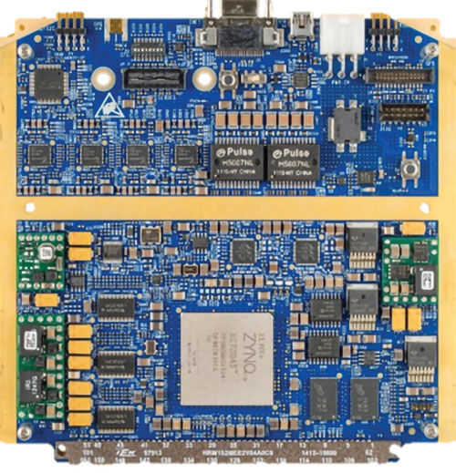
SERGEANT Flight Test SDR. (Image: Northrop Grumman)
Northrop Grumman foresees the world of GNSS being dramatically influenced by the emergence of alternative radio navigation sources as augmentations to traditional GNSS constellations to provide additional robustness and resilience. Our PNT SDR technology is a foundational tool to integrate these emerging radio navigation signals quickly and accelerate deployment to our customers.
Northrop Grumman has led medium-Earth orbit (MEO) and low-Earth orbit (LEO) PNT technology studies through the DARPA Blackjack proliferated LEO (pLEO) program, starting in 2017. Northrop Grumman’s SERGEANT SDR transceiver is currently being integrated for use in emerging pLEO constellations. We anticipate that these capabilities, as well as emerging cooperative radio navigation signals, will become a critical part of the next 50 years of PNT with GPS.
A Spirent user employs a portable GSS6450 attached to an antenna to record GPS, other GNSS, and complementary signals for resilient PNT testing. (Image: Spirent)
What is Spirent’s GPS origin story?
Spirent’s GPS genesis began on a rooftop in the middle of the night in the early 1980s. Engineers were attempting to acquire the new GPS signals with their receivers, scheduling their lives around the times when satellites would pass overhead, angling antennas off a roof in the dark, and hoping for favorable conditions. Those difficulties inspired an idea: since real-world conditions are never the same twice, simulating the signals in a lab would control variables and provide repeatable and trustworthy results.
That idea grew to be Spirent’s positioning division — a team of experts whose sole focus is to partner with customers to accelerate the deployment of robust PNT technology. In 1985, one of the first groundbreaking simulators provided to a customer generated six GPS L1/L2 signals. Soon after, we developed the world’s first simulator with SA-A/S capability, establishing our reputation for innovation. Today, simulation is for much more than convenience. The further upstream testing starts, the better for R&D and investment decisions. Because of that, we work across the spectrum in close partnership with constellation developers, receiver manufacturers, and OEM application integrators.
Can you share a recent breakthrough?
GPS regional military protection (RMP) is a nascent anti-jamming capability that uses a steerable, narrow-beam M-code signal, allowing U.S. and allied forces to operate much closer to interference without losing connection. Spirent supports RMP, so modernized GPS user equipment (MGUE) can be tested and integrated with RMP long before live-sky signals are available.
Another major breakthrough is in AltNav, a catch-all term that includes non-GNSS sources of RF and other complementary PNT, with recent attention focused on low-Earth orbit (LEO) constellations. Spirent has developed LEO AltNav simulators for both the military and commercial sectors that seamlessly integrate with Spirent’s extensive testbed for GNSS, threat simulation, inertial navigation systems, and additional complementary PNT.
How is your company preparing for the next 50 years of PNT with GPS and beyond?
As a trusted industry test partner, one of Spirent’s guiding principles over the past five decades has been to support PNT developers and early adopters by being first-to-market with new signals and constellations. Enabled by our flexible solutions, our dedication to that tenet will continue across the next five decades.
NAVWAR resilience testing is an area where emerging test needs will continue to demand more from the test environment. Layered PNT positioning engines — including GNSS, secure military signals, CRPA systems, multi-orbit architectures, and sensor fusion — are driving complexity in the test regimes that support them. Spirent’s purpose-built solutions are designed to meet these advancements, with deterministic simulation that delivers definitive validation and accurate test results.
Spirent pioneered the use of software-defined radios for GNSS simulation with the GSS9000, which enabled the same architecture to support new signal types, higher motion rates, user-defined waveforms, and more than double the generated signals. The next generation will extend that flexibility, capacity, and ease of integration to future complementary PNT sources while maintaining system performance across physical and virtual realms.
IBM, a global technology provider, has released its latest geospatial artificial intelligence (AI) initiative to address climate change. These efforts involve collaborations across various regions and uses advanced AI models designed for geospatial applications.
Central to these initiatives is IBM’s geospatial foundation model, developed jointly with NASA. These models aim to generate environmental insights and solutions related to climate change. Unlike traditional AI models, these use a vast amount of climate-relevant data to accelerate the analysis of various environmental aspects that are affected by climate change.
“AI foundation models utilizing geospatial data can be a game-changer, allowing us to better understand and address climate-related events with unprecedented speed and efficiency,” said Alessandro Curioni, IBM fellow and vice president of Accelerated Discovery.
Analyzing urban heat islands in UAE
IBM and the Mohamed Bin Zayed University of Artificial Intelligence (MBZUAI) have partnered to map urban heat islands in Abu Dhabi using a fine-tuned version of IBM’s geospatial foundation model. The goal of the project is to understand the impact of local landscapes on temperature anomalies, the company said. The initial results show a decrease in heat island effects, which can provide valuable insights for future urban design strategies.
Reforestation and water sustainability in Kenya
In partnership with Kenya’s Special Envoy for Climate Change, Ali Mohamed, IBM is supporting the National Tree Growing and Restoration Campaign. The initiative aims to plant 15 billion trees by 2032, particularly in critical water tower areas affected by deforestation. IBM’s geospatial model powers a digital platform to track tree planting activities, aiding local efforts in restoring forests and measuring carbon sequestration impact.
Elevating climate resiliency in the UK
In collaboration with the Science and Technology Facilities Council (STFC) and Royal HaskoningDHV, IBM is developing AI-driven tools for climate risk assessment in the UK. These tools will focus on assessing weather impacts on aviation operations, the company said. Additionally, the TreesAI research project aims to map areas suitable for tree planting to mitigate surface water flooding and offer urban developers a digital planning platform.
IBM extends collaboration with NASA for weather forecasting
IBM and NASA have partnered to develop an AI foundation model dedicated to weather and climate applications. The collaboration aims to enhance the accuracy and speed of weather forecasting, predict wildfire conditions and understand meteorological phenomena. IBM researchers will work closely with NASA to train and validate this model, IBM said.
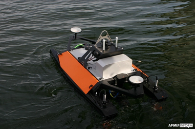
Maritime Robotics, a Norwegian provider of autonomous technology, and Teledyne Marine have delivered several unmanned surface vessels (USVs) to Ukraine’s Navy for advanced sensor data collection.
Maritime Robotics’ Otter USV, equipped with the Teledyne RESON SeaBAT T51-R multibeam echosounder, is now being used by Ukraine’s Navy. The USV is designed for critical data collection without endangering human lives, as the sensors are carried by an unmanned vehicle. The data and information collected by the USV aims to strengthen Ukraine’s defense, enhance maritime traffic security and support the safety of civilians in the areas.
Otter USV is part of Maritime Robotics’ portfolio of autonomous technologies capable of supporting military personnel in mapping and securing marine environments. Controlled and navigated remotely, Maritime Robotics’ USVs are designed to identify, locate and safely neutralize potential threats such as explosive devices and sea mines.
On Oct. 26, 2023, I participated in an American Society for Photogrammetry and Remote Sensing (ASPRS) Pacific Southwest Region Fall Technical webinar. The webinar provided an overview of the ASPRS Positional Accuracy Standards for Digital Geospatial Data (Edition 2, Version 1.0 – August 2023). The document can be downloaded here.
ASPRS Webinar Announcement. (Image: ASPRS)
I also participated — virtually — in the Nov. 2, 2023, California Spatial Reference Center (CSRC) Coordinating Council fall meeting where Dr. Riadh Munjy, California State University, Fresno, discussed the revisions to the ASPRS Positional Accuracy Standards for Geospatial Data.
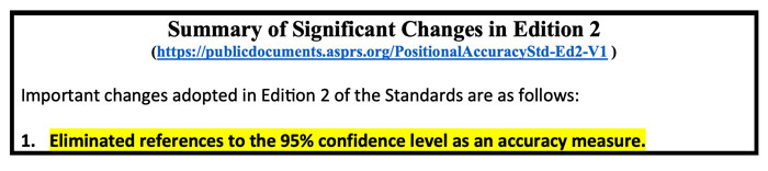
The most significant changes introduced in this second edition of the standards include:
Elimination of references to the 95% confidence level as an accuracy measure.
Relaxation of the accuracy requirement for ground control and checkpoints.
Consideration of survey checkpoint accuracy when computing final product accuracy.
Removal of the pass/fail requirement for Vegetated Vertical Accuracy (VVA) for lidar data.
Increase the minimum number of checkpoints required for product accuracy assessment from 20 to 30.
Limiting the maximum number of checkpoints for large projects to 120.
Introduction of a new term: three-dimensional positional accuracy.
Addition of Best Practices and Guidelines Addenda for:
General Best Practices and Guidelines
Field Surveying of Ground Control and Checkpoints
Mapping with Photogrammetry
Mapping with Lidar
Mapping with UAS
As outlined above, Edition 2 contains Best Practices and Guidelines for (1) General Best Practices and Guidelines and (2) Field Surveying of Ground Control and Checkpoints. The three addenda listed in the table of contents: Mapping with Photogrammetry, Mapping with Lidar, and Mapping with UAS will be available for public comment later, and will be added to Edition 2, Version 2.0.
Dr. Abdullah informed me that these addenda are on track to be put out for public comments during December 2023, therefore he believes they will probably be published in January or February 2024. The box titled “Summary of Significant Changes in Edition 2” provides the changes with the reason and justification for each change. The document can be downloaded from ASPRS here.
One of the changes is to relax the accuracy requirement for ground control and checkpoints. At first glance, this seems like the wrong thing to do. However, after understanding the justification, the requirement for ground truth still needs to be at least twice as accurate as the product.
Both Dr. Abdullah and Dr. Munjy’s emphasized in their presentations that the current accuracy requirements for ground controls in photogrammetric work of four-times better than the produced products, and the checkpoint accuracy requirement is three-times better than the assessed product. This makes it difficult, if it is not impossible, to use RTK-based techniques for this type of surveying. This by itself is not the reason for the change. During Dr. Abdullah’s presentation, he provided the following reasons for the change:
“Experience taught us that the requirements of four-times and three-times adopted in edition 1 of the standards are excessive and too restrictive, partly due to the reason outlined in (b) below.
Today’s sensors, software, and processing methodology are more accurate and the room for errors in the product is diminishing, therefore we do not need a safety factor of 3 or 4 to obtain accurate products.
Increasing demand for higher accuracy geospatial products.”
The new standards now factor in the accuracy of the survey checkpoints when determining the accuracy of the product. During Dr. Abdullah’s presentation, he provided the following reason for the change, “As we are producing more accurate products, errors in surveying techniques of the checkpoints used to assess product accuracy, although small, can no longer be neglected and it should be represented in computing the product accuracy.” He also highlighted that, “As product accuracy increases, the impact of error in checkpoints on the computed product accuracy increases.” The document provides equations used to compute the values. See below.
A very significant change, in my opinion, is the removal of the standards for Vegetated Vertical Accuracy (VVA) for lidar data. See below.
VVA not used as a criterion for acceptance. (Image: ASPRS)
I am not sure I agree with the reasoning, but I understand why it was done. GNSS-based surveys do not perform well in vegetated areas, and this is the technology used to validate the non-vegetated vertical accuracies (NVA). That said, there are non-GNSS technologies — sometimes denoted as traditional surveying methods — that could be used to validate VVA, so this seems like an elimination of a requirement based on the limitation of a particular technology.
Traditional surveying methods that use geodetic levels, theodolites, and total stations to measure distances, angles, and heights are still used by surveyors to perform certain projects. Since there are other surveying methods that could be used for evaluating the VVA, it does not seem like a valid reason for a change.
The ASPRS standards does state that, “for projects where vegetated terrain is dominant, the data producer and the client may agree on an acceptable threshold for the VVA.” Therefore, the client can require the surveyor to meet a specific accuracy level for vegetated areas. I am sure this was discussed during the working meeting, so I leave it to the experts to make the appropriate decisions and recommendations.
Finally, it should be noted that, as discussed above, the new ASPRS standards eliminated the reference to the 95% confidence level as an accuracy measure. The document provides the following statement about the National Standard for Spatial Data Accuracy (NSSDA):
“The National Standard for Spatial Data Accuracy (NSSDA) documents the equations for the computation of RMSEX, RMSEY, RMSER and RMSEZ, as well as horizontal (radial) and vertical accuracies at the 95% confidence levels — AccuracyR and AccuracyZ, respectively. These statistics assume that errors approximate a normal error distribution and that the mean error is small relative to the target accuracy. The ASPRS Positional Accuracy Standards for Digital Geospatial Data reporting methodology is based on RMSE alone, and thus differs from the NSSDA reporting methodology. Additionally, these Standards include error inherited from ground control and checkpoints in the computed final product accuracy.”
Appendix D of the ASPRS document provides the equations with an example for computing the accuracy statistics. The document also has a section with examples for users who wish to relate the ASPRS 2023 Standards to the FGDC National Standard for Spatial Data Accuracy (NSSDA).
Dr. Munjy ended his presentation at the CSRS 2023 fall meeting with the following statements:
“ASPRS Accuracy Standards 2023 have become more aligned with science and statistical theory,” and “These Standards are intended to be a living document which can be updated in future editions to reflect changing technologies and user needs.”
I would encourage all users to download the document to better understand the changes and reasons for the changes. It can be downloaded here.
Hexagon’s Safety, Infrastructure & Geospatial division has partnered with Pitkin County Regional Emergency Dispatch Center to upgrade its digital mapping and response for 911 calls in Colorado’s premier mountain tourist destination. The partnership aims to make the county safer for residents and visitors.
By using HxGN Connect software, Pitkin County can bring modern mapping capabilities to its computer-aided dispatch (CAD) system, as well as incorporate Smart Advisor, Hexagon’s assistive artificial intelligence solution.
Pitkin County, home of Aspen and its four major ski areas, hosts 1.5 million tourists per year. The upgrades will improve emergency response capabilities for major events such as the X Games and JAS Aspen music festival, the company says.
The cloud-based solution, hosted in Microsoft Azure, is designed to map 911 calls and conduct long-term resource planning. Smart Advisor will work in the background to help dispatchers and first responders connect related incidents and provide geofencing to concentrate resources on large events. Officials plan to expand the system to take advantage of its cross-organization collaboration capabilities by potentially linking the county’s CAD system with the fire department’s network of mountaintop smoke detectors and the Department of Public Works’ snowplows.
Pitkin County dispatchers will use HxGN Connect for digital mapping within its CAD system in the mountainous tourist destination.
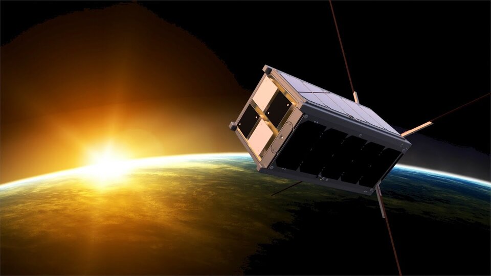
The Educational Irish Research Satellite, EIRSAT-1, has successfully launched from Vandenberg Space Force Base, California, on Dec. 1, 2023. Hitching a ride on a SpaceX Falcon 9 launcher, the small satellite has made history as Ireland’s first satellite.
Over the course of six years, EIRSAT-1 was designed, built and tested by students from University College Dublin (UCD) in Dublin, Ireland, participating in the European Space Agency (ESA) Academy’s Fly Your Satellite Program. The program is a hands-on initiative that helps university student teams develop their own satellites according to professional standards. The launch opportunity itself was provided by the ESA.
Throughout the development of the satellite, ESA experts provided training and guidance to dozens of UCD students, the ESA said. The students’ learning journey included test campaigns at ESA Education’s CubeSat Support Facility in Belgium, as well as dedicated spacecraft communications sessions at both ESA Academy’s Training and Learning Centre and the European Space Operations Centre in Darmstadt, Germany. These sessions were designed to teach the procedures for operating Ireland’s first spacecraft.
From low-Earth-orbit (LEO), EIRSAT-1 will carry out three main experiments, which were built from scratch by the students:
GMOD, a detector to study gamma ray bursts, which are the most luminous explosions in the universe and occur when a massive star dies or two stars collide.
EMOD, an experiment to see how a thermal treatment protects the surface of a satellite when in space.
WBC, an experiment to test a new method of using Earth’s magnetic field to change a satellite’s orientation in space.
Following EIRSAT-1’s deployment to orbit, the student team is now working to establish contact with the satellite and start operations from their dedicated ground control facility, also entirely operated by students and located at UCD in Dublin.
The U.S. Army has awarded Lockheed Martin and Northrop Grumman other transaction agreements (OATs) for the first phase of the Launched Effects (LE) program.
Launched Effects “will provide standoff sense and effect capabilities for soldiers while keeping air and ground forces outside the range of adversary weapon systems,” according to the service’s Program Executive Office for Intelligence, Electronic Warfare and Sensors. It also said LE will also support forces entering and exiting mission areas.
Northrop has been awarded for two payloads and Lockheed Martin has been awarded for one, with each award valued at about $100,000, according to the Army. The OTA will total about $37 million over all three phases.
The LE program consists of three phases. During that span, the Army aims to mature payloads from a technology readiness level of 6, a prototype system that has been tested in a relevant environment, to TRL 7, a prototype that has been demonstrated in an operational environment.
Launched effects have been successfully tested by the Army in the past, including at Project Convergence. In January 2023, General Atomics Aeronautical Systems announced its Eaglet launched-effect flew for the first time, dropping off an Army-owned Gray Eagle Extended Range UAV during a demonstration in Utah.
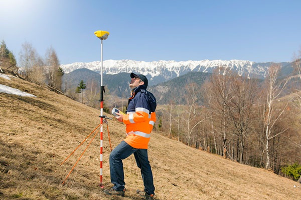
The Global Positioning System (GPS) project started 50 years ago, in 1973. I was fortunate to be part of incorporating GPS into the National Spatial Reference System (NSRS) when I worked for the National Geodetic Survey (NGS). GPS was not considered operational until 1993, but NGS started performing GPS surveys in 1983. Geodetic control surveys that formerly took six to 12 months to perform using classical methods could be performed with GPS in a few weeks using fewer personnel and resources. It changed the way NGS and others performed their surveying operations.
While one group in NGS was developing programs to evaluate and compute coordinates using GPS, another NGS group was completing the readjustment of the North American Datum of 1983 [NAD83 (1986)]. The analysis of GPS indicated that some of the latitude and longitude values estimated using GPS did not agree with the published NAD83 coordinates. The classical techniques used a triangulateration process (involving angles and distances) that required several triangles to connect two stations that were not intervisible. GPS, on the other hand, could directly measure the distance between the two stations, resulting in more accurate coordinate differences.
To support surveyors, NGS, working with other federal agencies under the auspices of the Federal Geodetic Control Subcommittee (FGCS), developed a GPS test network in the Washington, D.C., area to demonstrate whether a specific manufacturer’s GPS receiver and associated geodetic post-processing software was an accurate relative positioning satellite survey system. This facilitated the use of GPS for incorporating geodetic control in the NSRS. As mentioned above, GPS surveys exposed many inconsistencies between existing NAD83 (1986) control. Organizations such as NGS and state transportation departments that performed control surveys used GPS as soon as equipment met the federal testing requirements because it was more efficient and cost-effective than classical techniques. This led individual states to perform statewide geodetic network projects to upgrade their NAD 83 (1986) coordinates. These surveys were ultimately designated as High Accuracy Reference Networks (HARN).
In the beginning, the attitude of the individual surveyor accepting GPS was one of “trust after verifying.” Many surveyors considered it to be a “black box” that could not be trusted. Surveyors were accustomed to having angles and distances they could write down and check the results. Also, there were some key challenges and limitations of using GPS for surveying in the early days. This included the cost and size of the equipment, the peripheral devices required, the power requirements (including 12v car batteries and generators), “black box” computer processing software, obstructions near monuments, and limited visibility of GPS satellites.
Prior to GPS becoming fully operational, some surveys had to be performed in the middle of the night to have four or more satellites visible during the observing session. This required a significant amount of technical planning, which sometimes required complicated logistics for coordinating observing sessions. Also, at that time, most private surveyors did not perform control projects, so even though GPS may be more accurate, it was not more cost-effective than classical techniques for their typical projects.
Over time, after GPS became operational, more surveyors (and other professionals) embraced using GPS after the cost of receivers decreased, user-friendly processing software became available (e.g., NGS OPUS), Continuously Operating Reference Stations were densified (e.g., NOAA CORS), and statewide Real-Time Networks (RTN) were established (e.g., North Carolina RTN). GPS technology now underpins many sciences, large areas of engineering (such as driverless vehicles and UAVs), navigation, and precision agriculture. GPS (today GNSS) and its applications have changed the way surveyors and geospatial users perform their work, and the world has seen the development of applications that were not ever imagined 50 years ago.