IRNSS-1F, the sixth satellite in the Indian Regional Navigation Satellite System (IRNSS), launched at 4:01 p.m. IST on March 10 from the Sriharikota rocket port in Andhra Pradesh.
After PSLV-C32 lift-off from the Second Launch Pad with the ignition of the first stage, the subsequent important flight events, namely, strap-on ignitions and separations, first stage separation, second stage ignition, heat-shield separation, second stage separation, third stage ignition and separation, fourth stage ignition and satellite injection, took place as planned.
After a flight of 19 minutes 34 seconds, IRNSS-1F satellite was injected to an elliptical orbit of 284 kilometers by 20,719 kilometers inclined at an angle of 17.866 degrees to the equator (very close to the intended orbit) and successfully separated from the Polar Satellite Launch Vehicle’s fourth stage.
Lift-off of IRNSS-1F (Photo: ISRO)
After separation, the solar panels of IRNSS-1F were deployed automatically. The Indian Space Research Organization’s (ISRO’s) Master Control Facility (MCF) at Hassan, Karnataka, took over the control of the satellite.
In the coming days, four orbit maneuvers will be conducted from MCF to position the satellite in the Geostationary Orbit at 32.5 deg East longitude.
IRNSS-1F is the sixth of the seven satellites constituting the space segment of the Indian Regional Navigation Satellite System. IRNSS-1A, 1B, 1C, ID and IE — the first five satellites of the constellation — were successfully launched by PSLV on July 2, 2013; April 04, 2014; October 16, 2014; March 28, 2015; and Jan. 20 respectively. All five satellites are functioning satisfactorily from their designated orbital positions.
The entire IRNSS constellation of seven satellites is planned to be completed in this year. The seventh satellite, IRNSS-1G, is expected to be launched in the second half of this year. The full system comprises nine satellites — seven in orbit and two on the ground as standby.
Acoustically aided inertial navigation technology will enable a specialized sea vessel maintain dynamic positioning through GNSS disruptions in challenging environments.
Sonardyne Inc.‘s dual Ranger 2 Pro DP-INS systems aboard the ultra-light intervention vessel Brandon Bordelon will track remotely operated underwater vehicles (ROVs) during inspection, repair and maintenance activities, providing an independent position reference for the ship’s Marine Technologies Class 2 dynamic positioning system.
The Lodestar motion sensing instrument platform (attitude and heading reference system, or AHRS) is tightly integrated with Sonardyne’s acoustic positioning components, providing power and control of surface and subsea transceivers as well as instruments such as Doppler velocity logs. The seamless integration of acoustics and inertial technologies exploits the long-term accuracy and precision characteristics of acoustic positioning with the continuous availability and fast update rate from high-grade inertial sensors.
Specialized vessels such as this normally rely on GNSS and ultra-short baseline (USBL) acoustics as their primary sources of dynamic positioning reference data. However, a vessel’s station-keeping capability can be compromised if the USBL is affected by noise or thruster aeration and the GNSS signal is simultaneously interrupted. GNSS signal interruption is particularly common around Equatorial regions and during periods of high solar radiation.
Wideband Acoustic. The integrated acoustic-inertial system addresses this vulnerability, exploiting the long-term accuracy of Sonardyne’s Wideband 2 acoustic signal technology with inertial measurements.
The resulting navigation output can ride through short-term acoustic disruptions and is completely independent from GNSS.
The equipment includes Sonardyne’s ship-mounted inertial navigation sensor and two HPT 7000 acoustic transceivers. The HPTs have been installed on the Brandon Bordelon through hull deployment poles and are optimized for tracking and dynamic positioning in ultra-deep water.
The equipment includes three ring laser gyroscopes that measure the angular rate and three accelerometers that measure the specific force of the moving platform. The INS output is low noise and accurate in the short term, but degrades over time. Therefore, it must be seamlessly aided with complimentary acoustic positioning observations.
Ranger 2 DP-INS uses a tightly coupled integration of range and bearing measurements from seabed transponders to aid the INS and control integration drift.
Industry effort pushes beyond-LOS UAV flight
At the International Lidar Mapping Forum in February, two organizations announced an industry consortium to push for removal of barriers to use of drones in long-distance inspections.
The presentation by Sharper Shape and Edison Electronic Institute made the point that UAVs — specifically, lidar-equipped UAVs — offer potential for more frequent and more affordable inspection and data capture for overhead assets such as power lines. Currently, Federal Aviation Administration (FAA) regulations restrict commercial operations to visual line of sight (VLOS). The EEI Sharper Utility project will advocate for beyond visual line of sight (BVLOS) flights.
The presentation explored such issues as:
Types of information obtainable during UAV inspections and how that information can be used to improve infrastructure and asset management programs.
How UAVs provide a cost-effective alternative to traditional inspection methods, and the critical factors contributing to cost-efficiency.
Why industry-wide coordinated effort is required to institute change.
Steps and the key principles to enable commercial-scale drone operations for the electricity industry.
Identification of stakeholders and the regulators.
The anticipated date of permitted BVLOS drone flights in U.S. utility inspections.
The Eyes of Texas. In related news, Xcel Energy announced a UAV flight research and development mission that traveled beyond the operator’s line of sight during survey of a transmission line in the Canadian River Breaks region north of Amarillo, Texas, in early February. Two contractors piloted the lidar-equipped Vapor 55 drone. Xcel began using unmanned aircraft to visually inspect substations in 2015, and is the first utility to receive and use the FAA’s certificate of authorization to perform a mission for research and development purposes beyond visual line of sight.
Xcel Energy inspects 320,000 miles of electricity and natural gas infrastructure, including more than 1,000 substations, gas regulator stations and dozens of major power plants in eight states. GPS World will carry further news of this flight in a subsequent issue.
Indoor Nav at Vast Mobile World Congress
Add Infrared Aiding in Retail Show
A scalable indoor positioning hybrid technology from Pole Star of Toulouse, France, combining GPS, Wi-Fi, Bluetooth Low Energy beacons, and motion sensors, and MOCA of Barcelona, Spain, with a location-based mobile engagement platform, provided show navigation, guidance and tracking for the GSMA Mobile World Congress in February.
The joint solution delivers three service levels that combine users’ geolocation with other data to provide expanded contextualized messages. As many as 95,000 show attendees — iOs and Android users alike — were guided through the 240,000 square meters (2.6 million square feet) of the FiraBarcelona, receiving personalized notifications from an intelligent recommendation system based on proximity.
Using geofencing, the 2,200 exhibitors could interact with attendees and attract them to theirs booths. Finally, indoor location analytics enabled the event organizers to visualize and correlate behavior and preferences of attendees.
Infrared. Pole Star also announced at the Retail Big Show in New York in January that it is integrating its NAO Campus indoor positioning technology with the Pricer Product Location solution based on Infrared trilateration. The combination will enable shoppers, once inside a store, to optimize their shopping route and be guided to the products and promotions they are looking for. Hyper-local targeting for shoppers and Indoor location-based analytics for retailers and brands are among the benefits touted.
Pricer, based in Uppsala, Sweden, offers in-store automated product positioning using infrared (IR) communication, combined with tracking algorithms to calculate the position of its electronic shelf labels (ESLs). A typical Pricer label response signal is seen by multiple points in the communication network reading different signal strengths depending on the distance from the label.
Automated in-store product positioning in retail is a “holy grail” for retailers, according to the company. By mapping in real time where the products are placed on the sales floor using the IR technology, companies can engage customers in the aisles, help customers find products and manage product placement compliance.
The countdown for the launch of of a rocket carrying Indian Regional Navigation Satellite Sytem-IRNSS-1F began at 9:30 a.m. local time at the Sriharikota rocket port in Andhra Pradesh, reports the New Indian Express.
The Polar Satellite Launch Vehicle (PSLV) is expected to blast off around 4 p.m. on Thursday, March 10, following a 54-hour 30-minute countdown.
“Like the countdowns for the flight of many other earlier rockets, the countdown is progressing smoothly,” a senior official of the Indian Space Research Organisation (ISRO) told the newspaper.
IRNSS-1F will be India’s sixth navigation satellite. It has a design life of 12 years and carries two payloads. The navigation payload will be operating in L5-band and S-band; the ranging payload consists of a C-band transponder (automatic receivers and transmitters of radio signals), which facilitates accurate determination of the range of the satellite.
A highly accurate Rubidium atomic clock is part of the navigation payload of the satellite. IRNSS-1F also carries Corner Cube Retro Reflectors for laser ranging.
To date India has launched five regional navigational satellites (IRNSS-1A, 1B, 1C, ID and 1E) as part of a constellation of seven satellites to provide accurate position information service to users across the country and the region, extending up to an area of 1,500 km.
The entire IRNSS constellation of seven satellites is planned to be completed in this year. The seventh satellite, IRNSS-1G, is expected to be launched in the second half of 2016. The full system comprises nine satellites — seven in orbit and two on the ground as standby.
The first satellite IRNSS-1A was launched in July 2013, the second IRNSS-1B in April 2014, the third In October 2014, the fourth in March 2015, and the fifth in January of this year.
According to ISRO, with the operationalisation of five IRNSS satellites, the proof of concept of an independent regional navigation satellite system over India has been demonstrated for the targeted position accuracy of better than 20 meters, 24 hours a day.
A: Spoofing is normally associated with the creation of false signals in order to generate a position error, but the same technique may be used to distort a timing solution. With GNSS timing systems being used in critical infrastructure, like power supply, financial transactions and data network synchronization, disruption of timing solutions could have catastrophic implications. GNSS simulators can be used to test the vulnerability of current timing systems and also the effectiveness of potential mitigation techniques.
A: An expanded set of tests for anomalous conditions. The growing number of GNSS signals offers attractive performance benefits, but also multiplies exposure to GNSS errors and interference. Functional requirements are clear to the developer and are naturally developed first. Defining response to anomalies is a less clear task, which too easily becomes a secondary concern. To ensure coverage of the larger test space, multi-GNSS development now requires that anomalous cases be addressed earlier, at priority on par with core functional requirements.
A: Multi-Constellation performance. Using two or more constellations can significantly increase coverage under adverse, limited-sky-view situations. Using two or more frequency bands will combat interference and jamming, and deriving a PNT solution from multiple constellations is a great way to detect spoofing. Integrators/ developers should be using a simulator to verify how the system/receiver behaves under loss of sky view, jamming or spoofing when tracking any combination of multiple constellations.
A: The recent explosion of wearable technology has led to a proliferation of devices being used in “edge-case” situations, with receiver performance being put under greater pressure to perform in a multitude of potential scenarios. A record and replay simulator gives you real signals as opposed to modeled ones, allowing for GNSS product development to be conducted with absolute realism, resulting in greater robustness within the market.
A: The threat of intentional broadcasting of a fake GNSS signal is dangerously growing. GPS spoofing is real and not a military-only concern. The proliferation of SDR and open-source code make spoofing accessible to malicious people even without extensive knowledge in the field of GNSS. Most GPS receivers, as tests show, are vulnerable to spoofing, and no warnings are generated when it happens. Test engineers should definitely consider spoofing attack detection in their test plans.
Examining the interoperability of precise point positioning products
By Garrett Seepersad and Sunil Bisnath
INNOVATION INSIGHTS with Richard Langley
CARRIER PHASE. We’ve all heard the term and recognize it as a more precise observable for GNSS positioning, navigation and timing than code phase, more commonly called the pseudorange. The carrier-phase measurement is the phase of the received continuous radio-frequency sinusoidal waveform that “carries” the pseudorandom noise ranging codes and the navigation messages. The underlying carrier of a satellite signal can be recovered and its phase measured at regular intervals by the receiver once it locks onto the signal.
As long as there is no interruption in the carrier tracking, the receiver can generate a continuous series of measurements of the cumulative phase or cycle count including fractional cycles. The initial value at signal lock-on is arbitrary. Ideally, it would equal the exact number of cycles (and fractional cycle) of the waveform between the antenna of the satellite and the antenna of the receiver.
If that was the case, then we could simply multiply that cycle count by the wavelength of the carrier in meters, say, and we would have the initial geometric distance (or range) to the satellite. Then we could update this value as time progresses with the receiver’s measurements and have a continuous sequence of range values, which, when corrected for satellite and receiver clock errors and other effects, would allow the receiver’s position to be accurately determined. But because we don’t know the true initial cycle count, the carrier-phase measurements are ambiguous by a constant integer amount (when measured in cycles). This characteristic of the observable is referred to as the integer ambiguity.
It was realized early in the development of GPS, that if the integer ambiguity of carrier-phase measurements could be resolved, we would have a very precise observable for positioning, navigation and timing, some two orders of magnitude more precise than the code-based pseudorange. Instead of measurement precisions of tens of centimeters, we could have precisions of tenths of millimeters.
In the early 1980s using the few test GPS satellites in orbit at the time, surveyors and geodesists developed a series of clever techniques that allowed them to make use of carrier-phase measurements to determine the baseline between pairs of receivers by estimating combinations of the ambiguities as unknowns along with the receiver relative coordinates or, for short baseline work, use a calibration procedure before starting a survey.
Now jump forward a few decades. While it is still common practice to double difference carrier-phase measurements between pairs of satellites and pairs of receivers to determine relative receiver coordinates, the technique of precise point positioning or PPP, which uses carrier-phase (and pseudorange) measurements from a single user receiver, is growing in popularity. But, the integer ambiguity problem is still with us and has to be addressed by the analysis software. The ambiguities are often estimated as real- rather than integer-valued quantities, in part because of the contribution of satellite hardware biases to the carrier-phase measurements.
However, it is possible to resolve the ambiguities to integer values by using PPP ambiguity resolution products distributed by several research organizations. In this month’s column, we take a look at the interoperability of these products for increasing the reliability and precision of position solutions and reducing the time required for a solution to converge to a required level of accuracy.
Ambiguity resolution in precise point positioning (hereafter, PPP-AR) requires that hardware delays within the GPS measurements be mitigated, which will then allow for resolution of the integer ambiguities within the carrier-phase measurements. Resolution of these ambiguities converts the carrier-phases into precise “range” measurements, with measurement noise at the centimeter-to-millimeter level compared to the meter-to-decimeter level of the C/A- and P(Y)-code pseudoranges. If the ambiguities could be isolated and estimated as integers, then that information could be exploited to accelerate PPP convergence to provide, for example, few-centimeter horizontal positioning accuracy within tens of minutes or even minutes from a cold start.
Integer ambiguity resolution of measurements from a single receiver can be implemented by applying additional satellite products, where the fractional component — representing the satellite hardware delay — has been separated from the integer ambiguities in a network solution. One method of deriving such products is to estimate the satellite hardware delay by averaging the fractional parts of steady-state real-valued or floating-point (float) ambiguity estimates, and the other is to estimate the receiver clock offset in the pseudorange and carrier-phase measurements independently by fixing the undifferenced ambiguities to integers in advance.
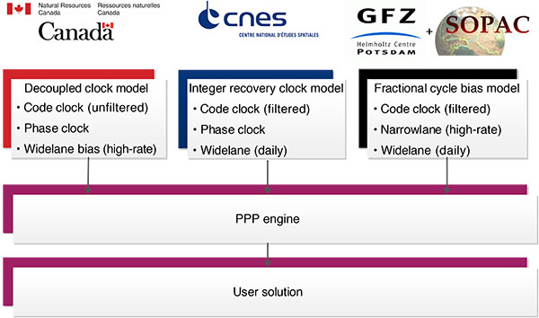
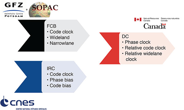
Similar positioning performances have been demonstrated among three approaches of different groups or agencies using the two methods: FCB (Fractional Cycle Bias), IRC (Integer Recovery Clock) and DC (Decoupled Clock). For the PPP user, the mathematical model is similar. The different PPP-AR products contain the same information and, as a result, should allow for one-to-one transformations, allowing interoperability of the PPP-AR products. The advantage of interoperability of the various products is to allow the PPP user to transform independently generated products to obtain multiple fixed solutions of comparable precision and accuracy, with no changes to the core PPP user software. An overview of the different providers and their products is presented in FIGURE 1.
FIGURE 1. Public providers of PPP-AR products. (Source: Richard Langley)
The ability to use different products would increase the reliability of a positioning solution in real-time processing, for example. If there was an outage in the generation of a particular PPP-AR product, a user could instantly switch streams to a different provider. The research presented in this article examines the PPP-AR products generated from the FCB and IRC models that have been transformed into the DC format and applied within a PPP user solution. The novelty of the research is the solution analysis using the transformed product. We examine the convergence time (time-to-first-fix and time to a pre-defined performance level), position precision (repeatability), position accuracy and solution outliers. The temporal and spatial behavior of these estimated terms is examined for the different products applied to understand the unmodeled effects responsible for incorrect solution fixes.
The Role of PPP-AR Products
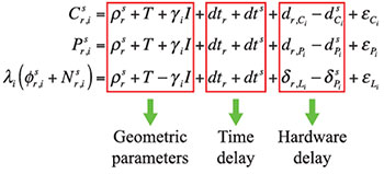
The standard GPS pseudorange ( and ) and carrier-phase () observation equations are given by
(1)
where i denotes the frequency-dependent GPS measurements for frequencies L1 or L2, s represents the tracked satellite, r represents the receiver, is the geometric range between the satellite s and the user position, T is the tropospheric delay, is the first order slant ionospheric delay, γi is the frequency dependent coefficient, dts is the satellite clock and is the pseudorange hardware delay. is the ambiguity term and is the carrier-phase hardware delay, both of which are expressed in cycles and scaled by the wavelength λi . The error sources can be grouped into two main components, the geometric parameters and the timing parameters. Included in the timing parameters are the clock offsets and the hardware delay terms. Understanding the role of the hardware delays is critical in isolating the integer ambiguities.
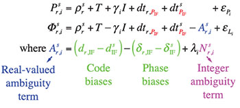
The following equations illustrate the effects of not mitigating the hardware delay. The set of equations was simplified by combining the clock and hardware delay parameters. Processing the carrier-phase measurements with the pseudoranges (code measurements) ensures that the pseudoranges provide a reference for the carrier-phase measurements and for the clock parameters. An implication of this is the manifestation of the hardware delay present in both the estimated clock parameters and the ambiguities.
(2)
By not mitigating the hardware delay terms ( and), they are absorbed within the estimated ambiguity terms, rendering the integer nature of the ambiguity term inaccessible. The user observation equations do not contain sufficient information to solve for an integer-ambiguity-resolved user position. Ambiguity resolution would only become possible if information about the satellite hardware delays were provided to the user. The receiver hardware delay can be removed by single differencing (between satellites).
In the following section, we present an overview of the different public providers of products that enable PPP-AR, their products and how they are applied to the PPP user equations.
Public PPP-AR Products
Currently, there are three main public providers of products that enable PPP-AR. These are Scripps Institution of Oceanography, which provides regional real-time FCB products; Natural Resources Canada (NRCan), which provides post-processed and real-time DC products; and Centre National d’Etudes Spatiales (CNES), which provides post-processed and real-time IRC products.
FCB Model. The initial application of ambiguity resolution to PPP was the Uncalibrated Phase Delay (UPD) model, now called the Fractional Cycle Bias (FCB) model. The FCB method estimates the hardware delay by averaging the fractional parts of the steady-state float ambiguity estimates to be removed from common satellite clock estimates. The FCB products consist of , and , where WN indicates the Melbourne-Wübbena (widelane ambiguity) combination and IF indicates the ionosphere-free linear combination.
DC Model. The underlying concept of the decoupled clock model is that the carrier-phase and pseudorange (code) measurements are not synchronized with each other at an equivalent level of precision. The timing of the different observables must be considered separately if they are to be processed together rigorously. The decoupled clock model is a reformulation of the ionosphere-free carrier-phase and pseudorange observation equations. When combined with the narrowlane pseudorange and the widelane phase, ambiguity resolution is possible. The DC products transmitted to the user are , and .
IRC Model. The integer recovery clocks estimate constant daily widelane pseudorange/carrier-phase hardware delays by averaging arc-dependent estimates. Using float-solution estimates of the range parameters, narrowlane ambiguity resolution is performed and the ionosphere-free satellite carrier-phase clocks are estimated. In 2014, the format of the IRC products was changed from , and to a state-space uncombined representation, such that the satellite hardware delay is provided for each observable (, ) and satellite pseudorange clock ().
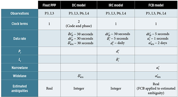
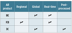
Summary. The three publicly provided products to enable real-time PPP-AR are listed in TABLE 1 along with their primary characteristics. The table summarizes the various measurements used, different products transmitted and the varying data rate of the transmitted products.
TABLE 1. Comparison of different publicly provided real-time products to enable PPP-AR.
Product Transformation
While the different strategies (FCB, FC, IRC) make different assumptions, there are fundamental similarities among them. The mathematical models for the PPP user are similar, as the different products contain the same information and as a result would allow for a one-to-one transformation. The following sections examine the transformation matrix used to transform the IRC and FCB products to the DC format (see Figure 2.)
FIGURE 2. Transformation of FCB and IRC products to DC input format.
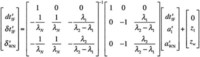
FCB. The FCB products consist of , and , which are estimated in the network solution using International GNSS Service (IGS) ultra-rapid orbit and clock products. The fundamental difference between the FCB and DC products is that is not determined in the DC method, but assimilated within the clock estimates. Also, is assumed constant over a 48-hour time period, whereas in the DC method the is neither constrained nor smoothed. Here is the transformation matrix used to transform from FCB to the DC model:
(3)
where z1 is the single-differenced L1 ambiguity and zw is the single-differenced widelane ambiguity.
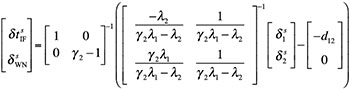
IRC. The original IRC products used a decoupled-like approach, where independent clocks ( and ) were transmitted for the pseudorange and carrier-phase measurements and widelane satellite hardware delays () were estimated. A redefined model was presented in 2014, where a state-space approach was adopted such that one phase bias per phase observable ( and ) was identified and broadcast. The primary benefit of such an approach is interoperability, allowing the network and user side to implement different ambiguity resolution methods. Here is the transformation matrix used to transform from IRC to the DC model: (4)
where d12 represents .
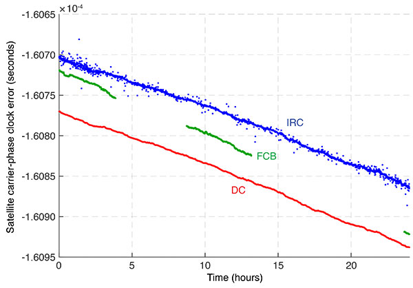
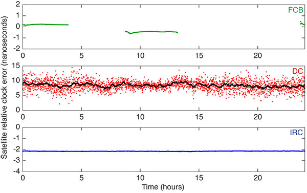
Analysis of Transformed Products. In FIGURES 3 to 5, we present the FCB and IRC products transformed to the DC format. The presented format was selected because it represents the nature of the transmitted real-time DC products. The philosophy of the DC model refers to the satellite hardware delay as an unmodeled timing error and, as such, the satellite carrier-phase clocks in Figure 3 are in units of seconds and in Figures 4 and 5 are in units of nanoseconds. Nanoseconds were selected because of the magnitude of the relative satellite pseudorange and widelane clock error, as well as being more bandwidth efficient.
FIGURE 3. Transformed FCB and IRC satellite carrier-phase clock correction on day-of-year 28 of 2015 for PRN 10. DC was included for comparison.
Figure 3 illustrates the FCB and IRC products transformed to the DC satellite carrier-phase clock. The satellite-clock corrections presented were not differenced with respect to a reference satellite, to illustrate their differences in an absolute nature. If the clocks are differenced, in a relative nature, they are equivalent. The data gaps in the FCB products are expected because of the regional nature of the products. Unlike the DC and IRC products, the FCB pseudorange clocks illustrate different trends such as those between hours 3 and 4. The noise illustrated in the IRC clock can be removed either by filtering or by differencing with respect to another satellite clock.
In Figure 4, we present the relative satellite clock error ( − ) for the transformed FCB (upper subplot) and IRC (lower subplot) products. For the original DC product (middle subplot), a simple moving average filter was applied with a bin size of five minutes to reduce the noise and illustrate the underlying equipment delay. The relative satellite clock error represents the difference between the pseudorange and carrier-phase clocks. The distinct differences of the products are easily visible, such as the filtering present within FCB and IRC products in contrast to the DC. The underlying relative satellite clock error is also significantly different in contrast to the DC product, such that FCB and IRC have an average relative satellite clock error of -0.041 ± 0.101 nanoseconds and -0.645 ± 0.005 nanoseconds, respectively, whereas the DC has an average of 8.465 ± 1.546 nanoseconds.
FIGURE 4. Transformed FCB and IRC products to code-phase relative clock correction on day-of-year 28 of 2015 for PRN 10. DC was included for comparison. Linear trend has been removed.
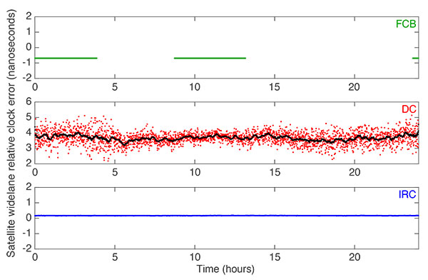
Figure 5 shows the relative satellite widelane clock error for the transformed FCB (upper subplot) and IRC (lower subplot) products. For the original DC product (middle subplot), a simple moving average filter was applied with a bin size of five minutes, to reduce the noise and illustrate the underlying equipment delay. The relative satellite clock error represents the difference between the widelane clocks and phase clocks. Similar to the relative satellite clock error, the differences in the transformed relative satellite widelane clock error are noticeable. As expected, the transformed FCB has a constant widelane estimate of -0.24 nanoseconds, whereas the transformed IRC and DC have an average widelane estimate of 0.0589 ± 0.002 and 3.6704 ± 0.34 nanoseconds, respectively.
FIGURE 5. Transformed FCB and IRC products to code-phase relative widelane clock correction on day-of-year 28 of 2015 for PRN 10. DC was included for comparison. Linear trend has been removed.
Performance of Transformed Products
One of the metrics we can use to examine the performance of the transformed products is the quality of the solution in the position domain. The solutions were examined with respect to the time for convergence to a pre-defined threshold and position stability. We used five stations from the Scripps Orbit and Permanent Array Center (SOPAC) network for days 23 to 30 of 2015. These five stations were selected because of the regional nature of FCB products provided by SOPAC. We show the results for site Brand Basin (BRAN) on day-of-year 30 of 2015 as it reflects the performance of the whole dataset processed.
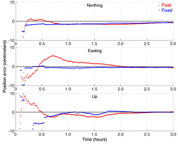
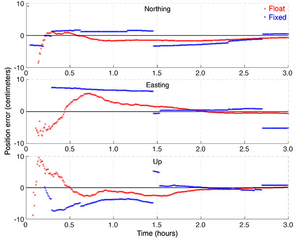
In FIGURES 6 to 8, we show the varying convergence periods at the site BRAN on day-of-year 30 for the “float” and “fixed” solutions using the different PPP-AR products, where fixed means the ambiguity-resolved solution and float the unresolved solution. Figure 6 uses the decoupled clock products, and the fixed solution performs as expected. After a few minutes, the solution attains the correct ambiguity candidate, and a fixed state is maintained.
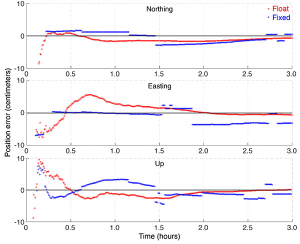
FIGURE 6. Position errors for site BRAN located in Burbank, Calif., on day-of-year 30 of 2015 illustrating the difference between the float and fixed solutions using the DC products.FIGURE 7. Position errors for site BRAN located in Burbank, Calif., for day-of-year 30 of 2015 illustrating the difference between the float and fixed solutions using the IRC products.FIGURE 8. Position errors for site BRAN located in Burbank, Calif., for day-of-year 30 of 2015 illustrating the difference between the float and fixed solutions using the FCB products.
The performance of the fixed solution using the IRC products is depicted in Figure 7. Initial convergence is similar to the DC products in the northing and easting components where a fixed state is attained after a few epochs. In the up component, the solution quality deteriorates after 30 minutes. What is also easily visible is the solution sensitivity to changes in the satellite geometry. As the number of satellites changes, the fixed ambiguities change, causing datum shifts in the user solution.
Similar trends were also observed when the transformed FCB products were used, with the results presented in Figure 8. The solution deterioration is most evident in the easting component, as the incorrect integer candidate is selected.
Challenges of Interoperability
Interoperability of the various PPP-AR products is a challenging task because of the different qualities of the publicly available products, limited literature documenting the conventions adopted within the network solution of the providers, and unclear definitions of the corrections.
In TABLE 2, we summarize the various qualities of the products we used in the study, showing why it was challenging to perform a consistent comparison. IRC products were generated from a network of reference stations globally distributed and in real time. Similar to the IRC products, the DC products were generated from a global network of solutions, but post-processed, and the FCB products were based on a regional network of reference stations, but were available in real time. Post-processed orbits and clocks have an accuracy of ~2.5 centimeters and ~75 picoseconds, respectively, whereas the predicted half of ultra-rapid orbits and clocks have an accuracy of ~5 centimeters and ~3 nanoseconds, respectively. While it is evident in the existing literature that PPP-AR is possible in real time, the solution is rather sensitive to changes experienced by the PPP user solution, such as varying local conditions and satellite geometry. The sensitivity is illustrated in Figures 7 and 8 with solution jumps typically occurring when there is a change in the number of satellites.
TABLE 2. Summary of the different quality of products provided by public providers to enable PPP-AR.
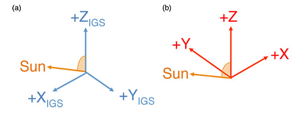
The general assumption when PPP-AR products are estimated within a network is that the PPP user would follow similar conventions when using the products. Consequences of different conventions adopted may result in incorrect ambiguities being resolved. For example, if inconsistent satellite antenna conventions were adopted between the network and user, then when phase wind-up corrections are applied, fractional cycles would be introduced. The introduced fractional cycles would result in incorrect ambiguities being resolved. FIGURE 9 shows the orientation of the spacecraft body frame for GPS Block IIR/IIR-M satellites adopted in the IGS axis convention (subplot (a)) and those provided in the manufacturer specifications (subplot (b)). The difference between the manufacturer specifications and IGS axis convention is the orientation of the x- and y-axes.
FIGURE 9. Orientation of the spacecraft body frame for GPS Block IIR/IIR-M satellites as (a) adopted within the International GNSS Service axis convention, and (b) those provided in the manufacturer specifications.
Conclusions
The mathematical model for the PPP user is similar for all PPP-AR products, as the different products contain the same information and, as a result, would allow for one-to-one transformations, allowing interoperability of the PPP-AR products. Interoperability of the various PPP-AR products would allow the PPP user to transform independently generated PPP-AR products to obtain multiple fixed solutions of comparable precision and accuracy. The ability to provide multiple solutions would increase the reliability of the solution such as in real-time processing: if there was an outage in the generation of the PPP-AR products, the user can instantly switch streams to a different provider.
We looked at the PPP-AR products provided by three organizations and examined position solutions for a set of stations in the SOPAC network with respect to convergence time to the pre-defined threshold and position stability.
Using the decoupled clock products, we found that the fixed solutions performed as expected. After a few minutes, a solution attains the correct ambiguity candidate and a fixed state is maintained. Unlike the fixed solutions using the decoupled clock products, instantaneous convergence was not attained in the horizontal and vertical components when the transformed IRC and FCB products were used. The ambiguity-resolved solutions were sensitive to changes in the satellite geometry. As the number of satellites change, the fixed ambiguities change, causing datum shifts in the user solution.
The unstable solutions from both transformed products are attributed to the magnitude of the relative satellite code and widelane clock errors. Additional refinement of the transformation model is required as the satellite hardware delay has not been completely mitigated. Mismodeling of the hardware delay was absorbed by the ambiguity terms, causing incorrect fixed solutions.
Future Research
Future prospective research includes refinement of the proposed transformation models to include the mismodeled effects, thus providing the user with a more reliable solution. The functional model needs to be further examined to ensure that the corrections were applied consistently. Further analysis of the instability of the user solution is required, as solution jumps typically occur when there are changes in the number of satellites tracked. Also to be analyzed are the post-fit residuals, to examine the effects of mismodeling. The temporal and spatial behavior of the estimated terms will be examined for the different products used to understand the unmodeled effects that introduce incorrect solution fixes. We would also consider increasing the number of reference stations to further test the reliability of the transformed products under varying user conditions.
Acknowledgments
We acknowledge Paul Collins, Jianghui Geng and Denis Laurichesse for our valuable discussions and their suggestions. The research was funded by the Natural Sciences and Engineering Research Council of Canada. The results we have presented were derived from data and products provided by Natural Resources Canada, Scripps Institution of Oceanography, Centre National d’Etudes Spatiales and the International GNSS Service.
This article is based on the paper “Examining the Interoperability of PPP-AR Products” presented at ION GNSS+ 2015, the 28th International Technical Meeting of The Satellite Division of the Institute of Navigation held in Tampa, Fla., Sept. 14–18, 2015.
GARRETT SEEPERSAD is a Ph.D. candidate at York University, Toronto, Canada, in the Department of Earth and Space Science and Engineering. He completed his B.Sc. in geomatics at the University of the West Indies and his M.Sc. in geomatics engineering at York University. His area of research currently focuses on the development and testing of PPP functional, stochastic and error-mitigation models.
SUNIL BISNATH is an associate professor in the Department of Earth and Space Science and Engineering at York University. His research interests include geodesy and precise GNSS positioning and navigation.
Further Reading
• PPP Ambiguity Resolution Techniques
“Review and Principles of PPP-RTK Methods” by P.J.G. Teunissen and A. Khodabandeh in Journal of Geodesy, Vol. 89, No. 3, 2014, pp. 217–240, doi: 10.1007/s00190-014-0771-3.
“A Novel Un-differenced PPP-RTK Concept” by B. Zhang, P.J.G. Teunissen and D. Odijk in Journal of Navigation, Vol. 64, Supplement S1, 2011, pp. S180–S191, doi: 10.1017/S0373463311000361.
“Isolating and Estimating Undifferenced GPS Integer Ambiguities” by P. Collins in Proceedings of the 2008 National Technical Meeting of The Institute of Navigation, San Diego, Calif., January 28–30, 2008, pp. 720–732.
“Resolution of GPS Carrier-Phase Ambiguities in Precise Point Positioning (PPP) with Daily Observations” by M. Ge, G. Gendt, M. Rothacher, C. Shi and J. Liu in Journal of Geodesy, Vol. 82, No. 7, 2008, pp. 389–399, doi: 10.1007/s00190-007-0187-4.
“Integer Ambiguity Resolution on Undifferenced GPS Phase Measurements and Its Application to PPP” by D. Laurichesse and F. Mercier in Proceedings of ION GNSS 2007, the 20th International Technical Meeting of the Satellite Division of The Institute of Navigation, Fort Worth, Texas, Sept. 25–28, 2007, pp. 839–848.
Improved Convergence for GNSS Precise Point Positioning by S. Banville, Ph.D. dissertation, Department of Geodesy and Geomatics Engineering, Technical Report No. 294, University of New Brunswick, Fredericton, New Brunswick, Canada. Recipient of The Institute of Navigation 2014 Bradford W. Parkinson Award.
INC 16 will address cutting-edge issues in positioning, navigation and timing. Of global importance, INC 16 will feature the latest developments in topics such as GNSS, indoor positioning, autonomous transport, security against cyber attack, resilience and quantum technology. Booking for the conference is now open.
The conference will include both peer-reviewed and non peer-reviewed tracks, and will cater to academic, industrial and end-user interests. The conference proceedings will be made available online in a digital repository in the weeks following the conference.
The abstract submission process varies depending on whether the paper is for the peer-reviewed or non peer-reviewed track:
Those wishing to submit a non-peer-reviewed paper for the conference should submit an abstract through the “Submit abstract” option on the conference home page, and can submit a paper for publication in the proceedings of any length. Non peer-reviewed submissions are due March 14.
Those wishing to submit a peer-reviewed paper should submit by March 14 a four-page short paper first, using the “submit short paper option” on the website’s home page. Following a selection process by the conference committee, successful authors will be invited to submit a longer paper (up to 10 pages) by June 15 for further peer review.
In February, I hit the 10-year mark with GPS World magazine. That milestone caused me to stop and reflect on all the changes in my work over the past decade.
In 2006, our web presence was mostly taking the print magazine and replicating it on the website, complete with a Table of Contents for the current issue. We had dozens of categories and subcategories, slicing and dicing the industry into micro-segments. I found it increasingly difficult to decide which category to place stories into, because so much research and so many products have multiple applications.
We’ve now greatly simplified the categories, but they still overlap. A Mobile story will touch on Transportation and OEM. A Survey story is also a Mapping story. A UAV story has applications for Defense or Mapping. Because of this, I invite you to see our categories as a jumping off point, not as independent silos. Peruse all the pages of our magazine — you may be surprised at what you find.
Another massive change over the past decade is our way of thinking. GPS World is no longer just a monthly print magazine with a now-and-then web story or editorial. We are the major industry web presence, with almost 1.5 million page views annually.
In 2006, I spent perhaps 20 percent of my time on the website. Today it’s closer to 80 percent.
In many ways, I have gone back to the early days of my career as a daily newspaper journalist to post news every day on both gpsworld.com and our sister Geospatial Solutions website. You can easily tap into these news streams through Twitter (which, coincidentally, is celebrating its 10th anniversary this month.)
I’m looking forward to another 10 years with GPS World, and I hope you come along for the ride.
Abstracts for ION GNSS+ 2016 are due Thursday, March 10.
ION GNSS+ 2016 is the 29th International Technical Meeting of the Satellite Division of the Institute of Navigation. The theme of this year’s conference is “GNSS + Other Sensors in Today’s Marketplace.” The conference will take place Sept. 12-16 (tutorials Sept. 12-13) at the Oregon Convention Center in Portland, Oregon.
ION GNSS+ 2016 is the world’s largest technical meeting and showcase of GNSS technology, products and services, and brings together international leaders in GNSS and related positioning, navigation and timing fields to present new research, introduce new technologies, update current policy, demonstrate products and exchange ideas.
ION GNSS+ 2016 features two different tracks, each with different abstract and manuscript submission requirements.
Applications and Advances Tracks
Mass Market and Commercial Applications
High Performance and Safety Critical Applications
System Updates, Plans and Policies
Research and Innovations Tracks
Multisensor Navigation
Algorithms and Methods
Advanced GNSS Technologies
Note: Submission requirements have changed and are dependent on the track for which you have submitted. Authors with abstracts accepted in the Research and Innovations Track will have the option to have their paper peer-reviewed.
Abstracts must be received by Thursday, March 10, 2016. For information on ION GNSS+ 2016 or for instructions for submitting an abstract, visit www.ion.org/gnss.
The next meeting of the Committee on Space Research (COSPAR) is expected to attract about 2,500 scientists and engineers from around the world. COSPAR Istanbul 2016: 41st COSPAR Scientific Assembly will be held July 30-Aug. 7 in Istanbul, Turkey. Deadline for early registration is May 31.
More than 100 symposia will cover all areas of space science:
space studies of the Earth’s surface,
meteorology and climate,
space studies of the Earth-Moon,
planets and small bodies of the solar system,
space studies of the upper atmospheres of the Earth and planets including reference atmosphere,
space plasmas in the Solar system, including planetary magnetospheres,
research in astrophysics from space,
life sciences as related to space,
material sciences in space,
fundamental physics in space, and
several panel meetings.
Interdisciplinary lectures will also be given by key scientists and several associated events, such as a meeting organized by Elsevier for young scientists to help them publish or review scientific articles.
Panel on Satellite Dynamics
A meeting for geodesists, organized by the COSPAR Panel on Satellite Dynamics, will be held in conjunction with IAG Commission 1.
The aim of the panel is to support activities related to the detailed description of the motion of artificial celestial bodies. This goal should be achieved by improving the current theories of motion and by evaluating their determining forces in a more sophisticated way.
Detailed theoretical understanding of the dynamics of satellites should coincide with the results of precise tracking in order to obtain the most precise knowledge possible of the orbit and the corresponding orbital positions.
Two different sessions (both as two-day meetings) are part of the Panel on Satellite Dynamics:
PSD.1 The scope of the Panel on Satellite Dynamics entails the positioning of a wide range of objects in space, including Earth orbiting satellites for Earth observation such as GRACE, GOCE, Swarm and the Copernicus Sentinels, and navigation satellite systems such as GPS, GLONASS, Galileo, BeiDou, QZSS or tracking systems such as SLR and DORIS. In addition, positioning plays an important role in the success of the continuously growing number of today’s and tomorrow’s planetary and solar system missions. Limiting errors in Precise Orbit Determination (solar radiation pressure, time variable gravity fields, phase center corrections, etc…) are of critical interest for many stakeholders. Moreover, formations of satellites are being realized and proposed for Earth observation and fundamental sciences, that impose very severe constraints on (relative) positioning and orbit and attitude control solutions (e.g. micro-propulsion). Satellite orbit determination requires the availability of tracking systems, well established reference frames and accurate station coordinate solutions, detailed force and satellite models, and high-precision time and frequency standards. Contributions are solicited covering all recent developments and plans in ground, satellite or probe positioning and navigation.
PSD.2 Global Navigation Satellite Systems (GNSS) are playing an increasing role in monitoring the Earth’s environment. Together with other space geodesy techniques (InSAR, DORIS, ICESat, LiDAR, GRACE/GOCE and Radar Altimetry, etc.), it can measure changes to the land surface geometry with millimeter accuracy, and sub-meter pixel resolution. This session will address current geodetic and remote sensing capabilities, sensing/imaging in order to measure and monitor terrain, ground moisture, water cycle effects, ice/snow melting, ocean circulation and sea state, atmospheric weather and climate, earthquakes and tsunamis, volcanic activity, and more, warning using a variety of geodetic and remote sensing techniques. Papers on combining GNSS with in-situ observations and other satellite or airborne sensor data, as well as discussing new applications for such systems, and future missions/challenges are also welcome.
European Space Solutions 2016 is a five-day conference that will bring together business and policy makers with users and developers of space-based solutions. The conference will take place at the World Forum Convention Centre in The Hague, The Netherlands, May 30 to June 3. Registration is free of charge, but mandatory.
The event will explore how space makes a difference to the lives, and livelihoods, of people across Europe and around the globe. Space-based services and technologies are the future of efficient, effective and sustainable services that society needs, organizers said. The conference is presented under the auspices of the 2016 Dutch Presidency of the Council of the European Union.
Participants will learn about new innovations that harness information from the European flagship space programs, Galileo and EGNOS (satellite navigation) and Copernicus (Earth observation), and the European Union’s Horizon 2020 research program, for a wide range of applications, gather insights about current developments and discuss what is possible and needed in the future.
The conference will be accompanied by a range of dedicated focus sessions and side events, opportunities and more.
European Space Expo
The conference also will run in conjunction with the European Space Expo, which comes to The Hague, The Netherlands, May 28 to June 5.
The expo presents information on European space programs ranging from satellite navigation (Galileo and EGNOS) to Earth observation (Copernicus) in an engaging and entertaining way. Highlights include the OmniGlobe — an interactive hologram of the earth’s atmosphere, an impressive model of a Galileo satellite, and many more.
More than 900,000 people have already visited the European Space Expo as it continues its tour of major European cities. The free exhibition highlights the many ways in which European Union space programs help Europeans “on the ground” every day.
The aim of the expo is to show citizens how European space policy and space-based technologies benefit their everyday lives on Earth and the importance of space technologies to the European economy and job creation.
Photo: GSA
The European Commission, with the strong collaboration and support of the European GNSS Agency (GSA), launched the European Space Expo in 2012. The popular, interactive and free exhibition illustrates the many services and applications that come from the European flagship space programs.
Free to the general public, record attendances have greeted the expo throughout its tour. 2016 is the fifth year of the highly successful road show, which has already visited cities from London to Larnaca and Rome to Riga. The expo was most recently in Luxembourg City, Luxembourg, Oct. 16-25, 2015.
ISS Reshetnev has signed a contract with Russian space agency Roscosmos to build 11 new GLONASS satellites, according to the Roscosmos website. ISS Reshetnev is Russia’s leading spacecraft developer and manufacturer.
ISS Reshetnev will build nine GLONASS-K1 satellites and two GLONASS-K2 satellites. The GLONASS-K1 satellites will be transition satellites between the existing GLONASS-M satellites and the future GLONASS-K2 satellites.
GLONASS-K2 satellites will begin flight tests in 2018, with mass production of GLONASS-K2 satellites to begin in the 2019–2020 time frame.
The GLONASS-K1 satellites are expected to have a 10-year lifetime. The first of the new batch of GLONASS-K1 satellites will be launched in 2018.
Flight tests of the two GLONASS-K1 satellites now in orbit have been completed.
— written with assistance from Richard Langley, “Innovation” editor.
At Caltrans District 7 in Los Angeles, we use the onboard GPS capability of smartphones to navigate in real time to the locations of proposed aerial targets and National Geodetic Survey (NGS) control stations.
Keyhole markup language (KML) files are created in the office using desktop GIS, then downloaded to smartphones for use in the field. We create KML files specifically for use by our surveyors during every aerial mapping project within Los Angeles and Ventura counties.
FIGURE 1. Highway Interchange displayed on a smartphone using Google Earth App for Android, (ground targets in blue, flight information for pilots in red and green). Airborne GPS positioning aids in controlling aerial photography as the pilot navigates from exposure to exposure. A flight management system automatically triggers the camera or sensor once it reaches the exposure station in the air.
KML is an extensive markup language (XML) notation for expressing geographic annotation and visualization within Internet-based, two-dimensional maps and three-dimensional Earth browsers. KML was developed for use with Google Earth — originally named Keyhole Earth Viewer.
The aerial target layer also shows the proposed locations of stereo model limits on the smartphone. A stereo model is the overlapping portion of two adjacent aerial images. Each typically has a 60 percent overlap with its adjacent image, so it can be viewed and mapped in stereo. The ground control is combined with the airborne GPS to provide the orientation of the individual exposures, and it establishes the coordinate space of that imagery for any subsequent products.
Having the stereo model limits as a data layer becomes a handy piece of information in the event an aerial target must be relocated because of unfavorable field conditions. The heads-up capabilities of GPS aboard the smartphones and KML files can also show the easiest path to reach either target location or control stations. The NGS control station layer hyperlinks to the NGS website, so the field surveyor always has the recovery note available in an electronic format.
The field surveyors are also given hardcopy maps of the target locations and control stations, but those are now only used as a backup to the KML files loaded onto the smartphones.
FIGURE 2. Phone Screen with station description from NGS database (above).FIGURE 3. The user arrives here via a hyperlink from another screen (FIGURE 2).
We have found that leveraging the onboard GPS capability of smartphones with GIS-based data layers in the field has increased production. Using smartphones provides the surveyors with information more concisely and clearly. This information enables surveyors to make better decisions in the field.
One example is identifying inaccessible areas. If the field surveyor sees that an aerial target can be moved to a different location that provides easier access, it can save time and guesswork.
This information is also valuable in rugged areas because the field surveyor may need to identify the location of hiking trails or while surveying in the desert, or identify the location of aerial targets in areas that are either lightly inhabited or have few landmarks. The project surveyor can tailor datasets specifically to project needed by the field surveyors.
Once the aerial targets have been placed and the NGS control stations recovered, the field surveyors then position the aerial targets and control stations using carrier-phase GNSS. This gives us the centimeter-level accuracy needed to control the aerial photography during our mapping projects.


 By Tracy Cozzens, Managing Editor


