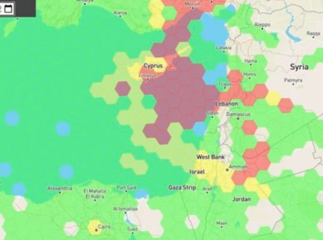
Just as I was beginning to write this article, war broke out between Israel and terrorist forces in Gaza. It would seem that the rockets used by Gaza were aimed rather than carrying on-board guidance, while Israeli airforce bomb/rocket attacks have been carried out with some degree of precision. Nevertheless, jamming in Israel may still be relevant to the ongoing conflict and any on-going commercial aircraft activity. However, it seems from the diagram of jamming below, that the Gaza strip is virtually interference free.
One of the things you can be sure of in the Ukraine-Russia war is that one side or the other is jamming the other’s communications and sat-nav guidance systems. An apparent consequence is that there is likely some “spill-over” to adjacent areas. For Israel, however, it looks like it’s more directed jamming rather than incidental.
Israel GPS jamming. (Image: GPS Jam.org)
In this environment of intentional GPS jamming, it’s not surprising that Israel has produced a leading anti-jam technology company, called InfiniDome, in Caesarea (between Haifa and Tel-Aviv). According to co-founder Omer Sharar, the company has been working to defend GPS signals for more than seven years and has also seen the rise of devices to jam the GPS L1 frequency that anyone can buy online for $100.
Just as Ukraine is throwing explosive cardboard UAVs with little cost at Russian occupying forces, a few carefully placed low-cost jammers could inflict serious damage on a country’s navigation capabilities.
However, a 2019 presentation by Todd Humphreys identified the source of interference and spoofing at that time, a Russian high-power jammer located at a Russian base in Syria.
Humphreys used instrumentation on the International Space Station (ISS) to gather data on the directed interference but concluded that the jamming in Israel could be a consequence of Russia’s efforts to protect its troops in Syria from UAV attacks. The Russian Khmeimim Air Base is on the Mediterranean coast and attacks are thought to come from rebels within Syria.
With the current GPS jamming out of Syria, most commercial aircraft traffic flying into Ben Gurion International Airport is significantly affected as flights cross from over the coast from the Mediterranean. Longer flight tracks deeper southeast into Israel are necessary, probably relying on VOR and DME ground station waypoints before turning back northwest to capture the instrument landing system (ILS) into the airport. This costs time and fuel and causes aircraft to overfly settlements where noise can be a real problem.
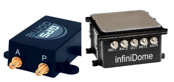
Most readily available jammer electronics only output interference disrupting GPS L1, which is most commonly installed for vehicle tracking and UAV guidance. InfiniDome has successfully protected trucking, UAV operations and others in Israel and around the world with its Infinidome GPSdome-1 and GPSdome-2 anti-jam products.
Two antennas 10 cm to 25 cm apart enable GPSDome-1 algorithms to detect and null out a GPS L1 jammer. GPSDome-2 accommodates up to four antennas and can null up to three directional signals on both GPS L1 and L2 or GPS L1 and GLONASS L1.
InfiniDome is currently working with an aerospace company to integrate its anti-jam technology with airborne inertial/GPS and qualify the integrated system for use in civil aviation, with the objective of maintaining max 3% drift when fully jammed. This will introduce certified anti-jam technology into civil aviation use — something that will provide some jamming protection, which airlines desperately need going forward. In addition, other high-end UAV manufacturers are potential customers for this new system.
While the ongoing conflict and the devastating loss of life is forefront as each day of the war passes, these anti-jam solutions may ultimately help solve signal degradation problems. While there is going to be a significant impact on commercial airline travel to and from Israel while hostilities continue, we can maybe see the way to a possible long-term solution for the intense jamming from which the region has suffered for many years.
The natural sciences overlap — hence such fields as geophysics, astrobiology and biochemistry. So do the social sciences and humanities — hence such fields as political economy, political philosophy and social economics. Our very individual identities consist of multiple, intersecting factors — including gender, race, ethnicity, class, and sexuality.
Analogously, this magazine covers overlapping technologies. While we focus on global navigation satellite systems (GNSS) and other positioning, navigation and timing (PNT) technologies such as inertial systems, these technologies are often embedded in larger systems that also include sensors (such as lidar, radar and cameras) and, increasingly, artificial intelligence (AI).
That is why we so often cover unmanned aerial vehicles (UAV) — which use GNSS for positioning navigation, geofencing and stabilization; use sensors to collect data; and will soon use AI for mission planning and execution — and autonomous vehicles — which use GNSS and sensors for positioning and navigation and already use AI to make driving decisions in complex environments.
Of course, UAVs are also much in the news these days:
Since the start of the Russian invasion of Ukraine, both sides have been using several hundred UAVs every day. According to the Royal United Services Institute, a British think tank, the Ukrainians are losing some 10,000 UAVs a month on the battlefield. (By way of comparison, the French army currently has a little more than 3,000 UAVs in its arsenal.)
In the United States, the number of companies granted waivers by the Federal Aviation Administration to conduct beyond visual line of sight (BVLOS) operations keeps growing, enabling them to conduct much more efficient monitoring, inspections and mapping of infrastructure.
Following a recent increase in encounters between swimmers and sharks along beaches on Long Island, New York, in July UAVs began sweeping the ocean three times a day to detect danger. On July 14, the state’s governor, Kathy Hochul, announced the allocation of $1 million to purchase 60 new shark-monitoring UAVs.
Also in July, 350 UAVs were lost during a practice light display show in Melbourne, Australia, ahead of a scheduled performance for the opening of the women’s World Cup. The UAVs appeared to stop mid-show and plummet into the Yarra River, most likely due to interference with GPS signals.
On August 30, researchers in Switzerland unveiled a small AI-powered quadcopter UAV that can outfly some of the best human competitors in the world. It whipped its way around an indoor racecourse in a matter of seconds and was able to beat its human rival in 15 out of 25 races, according to the journal Nature.
From mapping coastal areas with airborne lidar bathymetry to delivering medicines, from locating lost hikers to mapping fires, from enhancing the situational awareness of first responders to monitoring invasive plant species, UAVs are quickly becoming ubiquitous and essential.
Meanwhile, in San Francisco, where autonomous vehicles are already ubiquitous, but not everyone considers them essential, an anonymous group of protesters is surreptitiously placing orange traffic cones on some of them, confusing their sensors and rendering them inoperable.
Clocks are at the heart of GPS. Advances in space-qualified atomic clocks that kept time to within 10 nanoseconds over a day were a key development that made GPS possible. It turns out that GPS must account for both special relativity and general relativity to deliver position at 1-meter level and time at 100-nanosecond level to its users. We’ll use these round numbers as user expectations from GPS.
In the simple engineering analysis below, we consider the problems that would have arisen if the engineers had ignored relativity in their design of GPS. The issues related to positioning and time transfer are distinct, so we treat them separately.
GPS is basically a bunch of synchronized, near-perfect clocks in orbit
It’s a mantra worth repeating: To measure ranges to GPS satellites with meter-level accuracy, the clocks on the satellites must keep time with nanosecond-level accuracy.
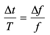
The clocks aboard GPS satellites are extraordinarily stable, typically to one part in 1013 over a day, which is another way saying that they could gain or lose on average 10-8 seconds, or 10 nanoseconds, over 105 seconds, which is roughly the length of a day. It’s a simple calculation. Suppose you measure a time interval of length with an oscillator advertised to have frequency f by counting its periods of oscillation. If the actual frequency is (f + Δf ), you’d measure the time interval as (T + Δt). It is easily shown that:
The fractional frequency stability (f / Δf ) is a key parameter. For an oscillator with stability (f / Δf ) of 10-13 over a day, as noted above, we can limit to 10 nanoseconds on average with data uploads to satellites once a day to re-sync the clocks. An error of 10 nano-seconds in time amounts to an error of about 3 meters in range computation and, speaking roughly, an error of about 3 meters in the position computed by the receiver. We can live with that.
Gravitational and motional effects on GPS clocks
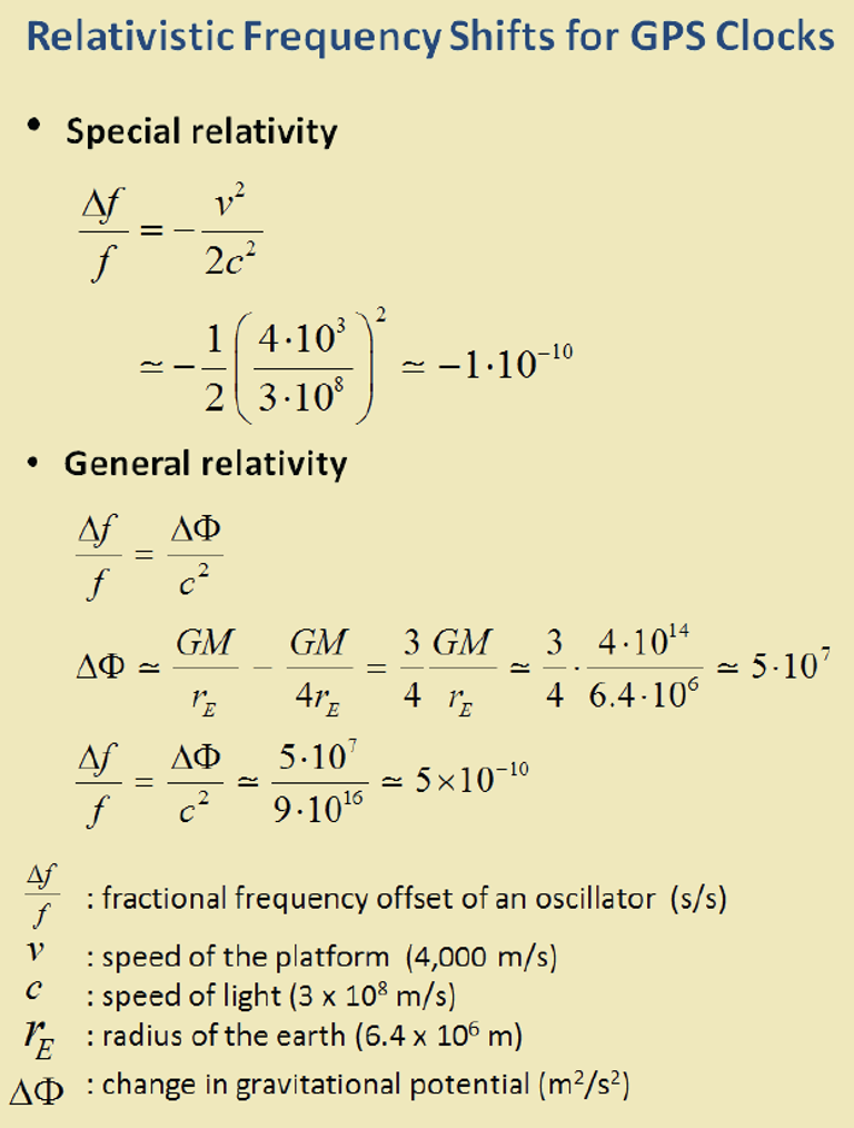
Our previous calculation of the timekeeping error of a satellite clock would have been fine had we not overlooked an important fact: We pretended as though the clocks were at rest on Earth at mean sea level. So, let’s see what relativity has to say about clocks in 20,000-kilometer-high circular orbits around Earth. The satellite orbits are not perfectly circular, or identical, but for now let’s pretend that they are. We call that modeling. The clocks would move at a rate of about 4 kilometers per second and exist in an environment where Earth’s gravity is only about one-fourth that at sea level.
According to the theory of special relativity, a moving clock ticks more slowly when compared with one that’s stationary at sea level. A clock aboard a GPS satellite will lose about 7 microseconds per day. That is three orders of magnitude larger than our budget for satellite clock error discussed earlier, therefore we can’t simply ignore it.
According to the theory of general relativity, on the other hand, a clock in a weaker gravitational field will tick faster than one that’s stationary at sea level. Apparently, gravity weighs down time, too. A clock aboard a GPS satellite in a medium Earth orbit will gain about 45 microseconds per day over a clock that’s at sea level on the earth.
The net effect: A GPS satellite clock will gain about 38 microseconds per day over a clock at rest at mean sea level. This effect is secular, meaning the time offset will grow from day to day.
So, you ask: Can you show me how you came up with these numbers, 7 micro-seconds and 45 microseconds? No, but I can point you to the references listed below and I can come close using simple mathematical models: (i) Earth’s gravitational potential is complicated and to simplify things we model Earth as homogeneous in composition and spherical in shape with a radius (rE) of 6,400 kilometers; (ii) aGPS satellite orbit is a circle with radius 4 rE; and (iii) the satellites move at the rate of 4 kilometers/second. We saved ourselves a lot of trouble by agreeing on this simple model.
sidebar
The calculation of the fractional frequency stability (f / Δf ) due to the relativistic effects is now easy and given in the sidebar. The answers are only approximate, but surprisingly close to the numbers cited above. That’s the beauty of good models. To calculate time gained or lost over a day, multiply by the length of a day in seconds.
As an interesting aside, note that the effects predicted by special relativity and general relativity cancel each other for clocks located at sea level anywhere on Earth. Consider two clocks, one located at the North or South Pole, and the other at the equator. The clock at the equator would tick slower because of its relative speed due to Earth’s spin, but faster because of its greater distance from Earth’s center of mass (about 22 kilometers) due to Earth’s flattening. Because Earth’s spin rate determines its shape, the two effects are not independent, and it’s no coincidence that they cancel exactly.
What if GPS forgot about relativity?
What would have happened if the engineers responsible for designing GPS had disregarded relativity? If the GPS satellites were in fact in identical, circular or-bits, their clocks would have shown a puzzling, but identical, behavior of gaining time over clocks of the Control Segment on Earth at a steady rate, about 38 microseconds over a day, the combined effect of special and general relativity.
What would that do to range measurements? A GPS receiver would have meas-ured the ranges to all satellites in view as too short by a common amount (up to about 11 kilometers between daily uploads of clock corrections). However, GPS receivers don’t measure ranges. To measure ranges, the receiver clock would have to be synchronized with the satellite clocks, an onerous requirement. The receivers use inexpensive clocks that drift and have frequency stability no bet-ter than . The receivers measure pseudoranges, i.e., ranges with a common bias on account of the receiver clock offset relative to GPS Time. This bias is es-timated by the receiver, along with its three-dimensional position. The price of an inexpensive receiver clock is that we now have four parameters to estimate and need pseudorange measurements from four satellites.
So, what would that do to positioning? The answer is that the common bias introduced by the relativistic effects would get lumped with the typically much larger bias introduced by the offset in the receiver clock. The position estimate would be unaffected.
Now, what about time from GPS? A GPS receiver used for timing is typically stationary with its antenna location carefully surveyed. In principle, a single pseu-dorange measurement can sync it to GPS Time (and UTC). So, if the relativistic effects had been ignored, the timing accuracy would have suffered to the ex-tent of 38 microseconds per day between updates of the clock parameters. That’s a deal-breaker, considering that we expect 100-nanosecond accuracy.
The relativistic effects discussed so far can be compensated for easily by setting the frequency of the satellite clocks lower (by 0.0045674 hertz) in what’s called “factory offset”: The frequency of a satellite clock is set to 10.22999999543 megahertz so that it will tick in orbit at the same rate as a 10.23-megahertz atomic standard at sea level on Earth. What an ingenious solution!
This factory offset would have accounted for the relativistic effects completely if the GPS satellite orbits were perfectly circular and identical. They are not. You can’t control an orbit perfectly.
So, what about eccentric orbits?
Yes, that’s a complication.
Each orbit is distinct and slightly elliptical. A consequence of this is that the sat-ellite speed is not constant (due to Kepler’s second law): the farther away a sat-ellite gets from Earth in its elliptical orbit, the slower it moves; and the farther away the satellite, the lower is the gravity field. That means the clocks in differ-ent satellites are speeding up and slowing down at different times and at differ-ent rates. The effect for each clock is periodic and quasi-sinusoidal. Averaging the effect over an orbit, we get zero.
For a satellite in an orbit with an eccentricity of 0.02, the net effect is that a clock can be ahead or behind by as much as 45 nanoseconds. The corresponding range error would amount to ± 15 meters. This effect must be accounted for specifically for each orbit. It would require serious bookkeeping on where the satellite has been in its elliptical orbit since the last data upload to sync its clock. It’s a messy business but can be simplified. We’d leave it at that. See ICD-GPS-200C, Section 20.3.3.3.3.1, if you want to see how it is implemented in your GPS receiver.
There is more to relativity than the special theory and general theory. There is the Sagnac effect associated with our rotating reference frames attached to Earth, in which we’d like to determine a position. The principle of constancy of the speed of light cannot be applied in a rotating reference frame, where the paths of the radio rays are not straight lines, but spirals. (Receivers at rest on Earth are moving quite rapidly: 465 meters per second at the equator.) There is also the Shapiro delay associated with the slowing of electromagnetic waves as they near Earth, which amounts to a fraction of a nanosecond. See the refer-ences for more on these topics.
Final thought: Could Einstein have imagined one hundred years ago that a bil-lion people would unknowingly account for the effects of his esoteric theory in their everyday activities?
Refrences
Ashby (1993), “Relativity and GPS,” Innovation column in GPS World
Back in the late 1980s, as project manager of the new adjustment of the North American Vertical Datum of 1988 (NAVD88), I worked with federal and state agencies to perform geodetic leveling and replace lost benchmarks. One of the reasons for the NAVD 88 project was to address the issue that thousands of benchmarks placed in previous decades had been subsequently destroyed and many others had been affected by crustal motion, postglacial rebound, and subsidence due to the withdrawal of underground fluids. NGS along with its partners performed thousands of kilometers of leveling to replace lost benchmarks. That said, the loss of control marks, denoted by some as “passive marks,” still seems to be a problem today.
California surveying agencies played a part in replacing and updating lost marks for the NAVD 88 project and it seems that they are doing it again. On Sept. 21, the importance of saving passive marks was discussed at the 2023 CLSA Geomatics Conference at Cal Poly Pomona/College of Engineering.
Defining passive marks
Several of my previous columns have highlighted the new, modernized NGS National Spatial Reference System (NSRS), and how active and passive control will be part of the new system.
Active and passive control. (Image: NGS)
For all practical purposes, passive marks are marks that are not continuously operating reference stations (CORS).
On June 22, NGS held a webinar on the benefits and challenges of transitioning to the modernized NSRS at which the presenters were not NGS employees. Users can download the presentation here.
NGS webinar on June 22. (Image: NGS)
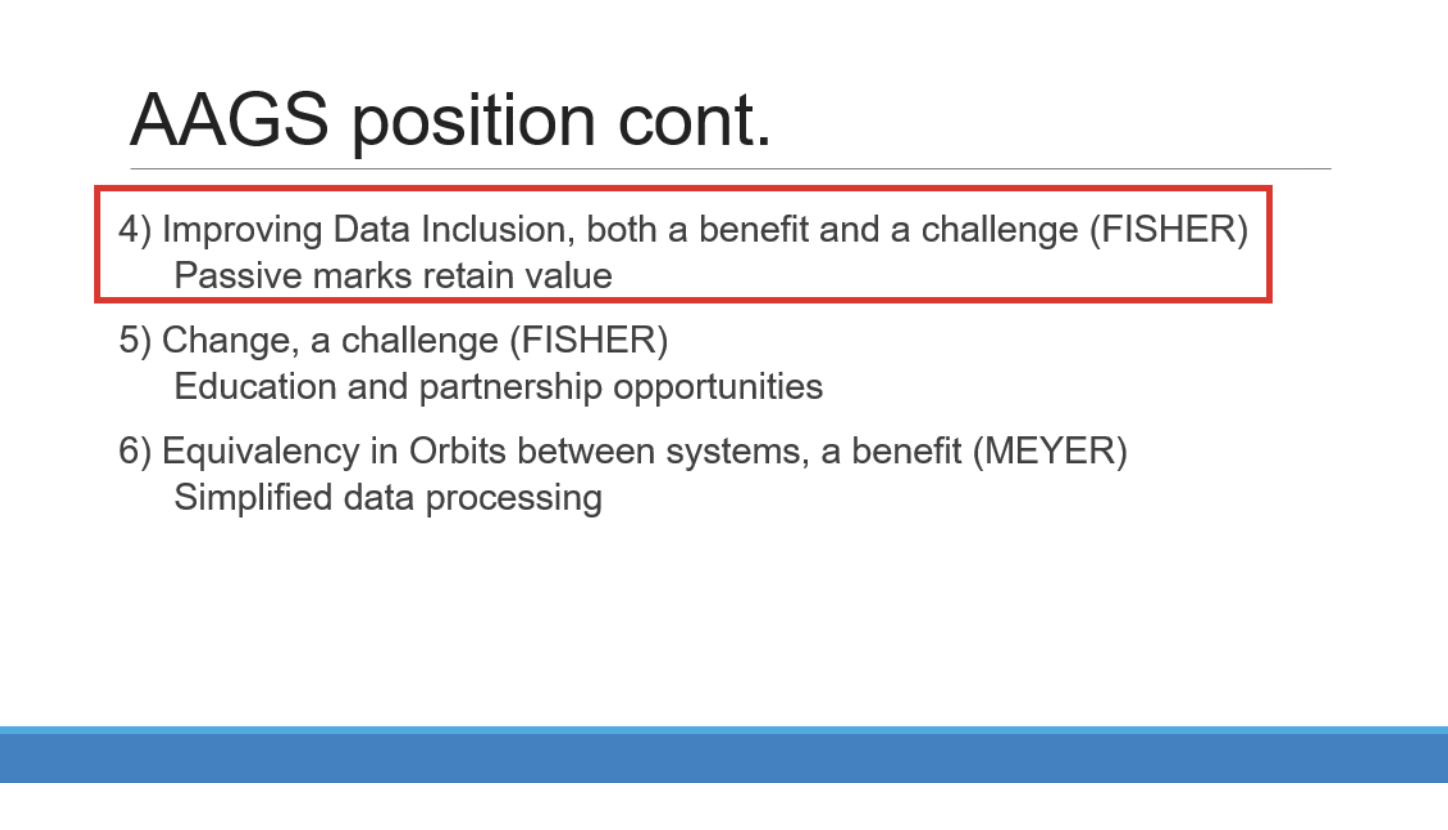
I want to highlight a few statements made by Brian Fisher, director of the American Association for Geodetic Surveying (AAGS). Readers can find more information about AAGS here. First, one of Brian’s slides stated that passive marks retain value and that improving data inclusion is both a benefit and a challenge. During his presentation, Brian stated that “passive marks are always going to have some level of value.” He also mentioned that “NGS has done a great job on improving the data submitting process.” NGS is developing models and tools for users to transition to the new NSRS. Tools such as OPUS Projects aim to help facilitate incorporating passive marks into the new, modernized NSRS.
(Image: NGS)
Brian is not the only one who knows the importance of passive marks. As previously mentioned, the importance of saving surveying control marks was highlighted at the 2023 CLSA Geomatics Conference at Cal Poly Pomona/College of Engineering.
2023 CLSA Geomatics Conference. (Image: Cal Poly Pomona)
At the conference there was a panel session on saving survey monuments.
The following is the abstract of the panel session:
“To discuss an ongoing problem of the destruction of land survey monuments and what the League of California Surveying Organizations (LCSO) and the California Land Surveyor’s Association aredoing about it.”
The panel consisted of five California County surveyors including David Farrell (LA Deputy County surveyor), Tom Herrin (San Bernardino County surveyor), Michael Lafontaine (Orange Deputy County surveyor), David McMillan (Riverside County surveyor), and Warren Smith (Tuolumne County surveyor). The presentation included discussion of a Monument Preservation Brochure and a Monument Preservation Guide.
Surveyors, engineers, and GIS professionals realize that inaccurate measurements can lead to boundary disputes, errors in construction projects, and environmental impacts. Passive marks are useful for validating measurements and spatial analysis. The panel noted that marks across California are in danger of being damaged or destroyed due to construction or insufficient public awareness. It was noted that addressing the loss of passive marks is important for maintaining California’s geographic information systems and preventing/averting legal disputes.
A goal of the guide is to provide individuals that oversee engineering work with strategies to save passive marks that are important to land boundaries and geospatial data.
The panel realized that survey monument preservation requires a collaborative effort from various stakeholders. By incorporating outreach, accurate locating techniques, efficient reporting systems and meticulous replacement strategies, California can safeguard its survey monuments for current and future generations.
The proposed guide will address the problem and outline a solution. The problem section would include topics such as lack of awareness, inadequate reporting, lack of funding, and the responsibility of the community. I have been informed that the guide will be posted here soon.
The panel members understood that the solution starts with outreach efforts and their draft guide lists the following potential outreach activities:
Educational campaigns at local schools, community centers, and public events to introduce the importance of survey monuments and their role in land ownership, land surveying and mapping.
Community workshops with local civic organizations, homeowners’ associations (HOAs), and chambers of commerce to conduct workshops focused on survey monument preservation.
Public awareness materials such asinformational brochures, posters, and online resources that explain the significance of survey monuments and the potential consequences of their damage or loss can be distributed through public libraries, city halls, and online platforms.
Media engagement with local media outlets can elevate public awareness and reinforce the importance of preserving these markers.
As part of the public awareness material the group has prepared a draft brochure. They mentioned that having a website, such as the CLSA website, be a hub for contacts and information for research may help support the “save the mark” campaign. They included that GIS web maps will be a common place to find monuments and survey control.
The draft brochure states, “destruction of survey monuments within the public rights-of-way, mainly as the result of public works projects and private developments permitted by public agencies, is increasing, due to a lack of oversight and education concerning the importance of these monuments.”
The draft brochure addresses the following questions:
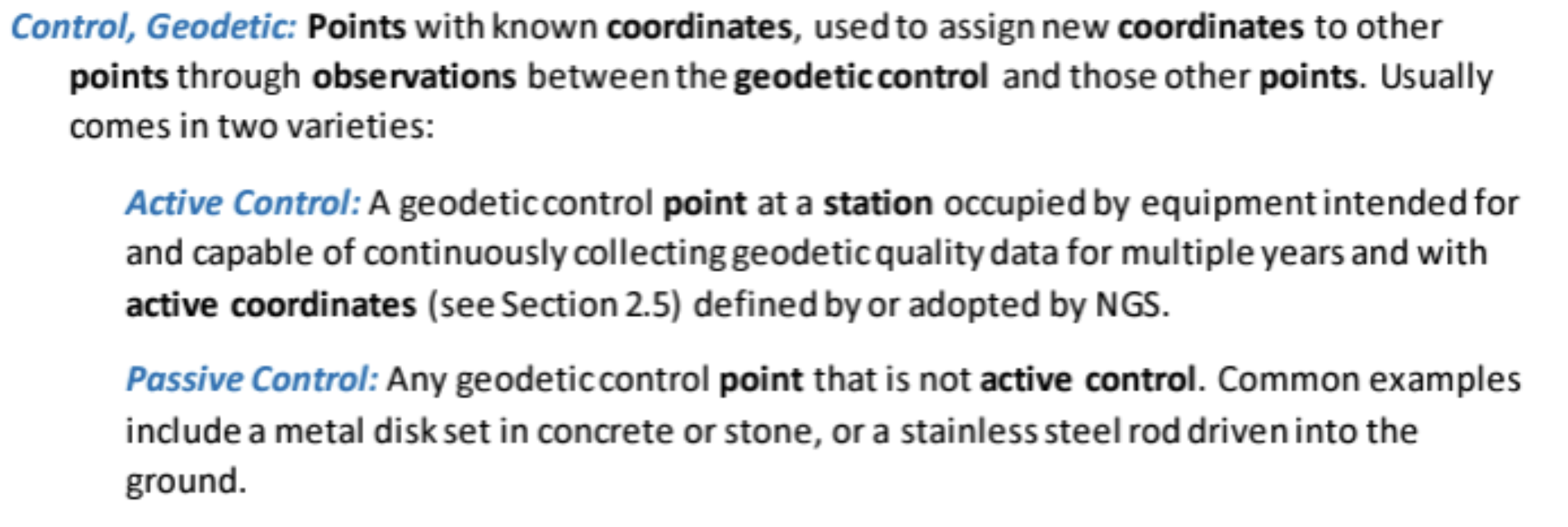
What Are Survey Monuments, Bench Marks & Geodetic Control?
Why Are They Important?
What Can You Do to Preserve Survey Monuments?
Who Is Responsible?
How Many Survey Monuments Are Really Needed?
The use of passive marks is well known to land surveyors since they use these marks in their daily operations as described in the statement above. It is crucial to be informed of the importance of passive marks and what they can do to help preserve them. Any professional involved in urban development can have a role in saving passive marks from destruction.
The draft brochure outlines the following actionable steps that others can take: show all existing land survey monuments on improvement plans, grading plans, site plans, etc.; educate engineers, surveyors, plan checkers, inspectors, GIS professionals, and the public about the importance of monuments and the requirements to preserve them; prior to filing notice of completion for any project, have a licensed land surveyor validate that the monuments are in place; and request acknowledgement via a written statement in the permit process, that a licensed land surveyor has performed a field inspection and that no monuments are subject to destruction within the scope of the project, or that existing monuments have been referenced and perpetuated per Business and Professions Code §8771.
The section “How Many Survey Monuments Are Really Needed?” is kept simple and straightforward: all of them! These monuments are set to allow for the retracement (or to mark the location) of features and legal rights on Earth’s surface.
There are many scientists who believe that active control stations are the solution to the surveying and mapping community’s positioning requirements.
I believe active control stations such as NOAA CORS Network (NCN) that NGS promulgates are extremely important to the development and implementation of the NSRS. In the new, modernized NSRS access to the geometric component of the NSRS will effectively be defined by CORS and their coordinate functions. That said, this does not diminish the importance and requirement for maintaining and updating the coordinates of passive marks.
The brochure is still a draft document and was not ready for publication at the time of this newsletter, but I have been told that it will be sent to all California county surveyors with instructions on what the goal is. Also, I have been informed that, as soon as it is publicly available, it will be placed on the websites of the California Land Surveyors Association and The League of California Surveying Organizations.
I am encouraged by what California surveyors are doing to highlight the importance of passive marks. I would be interested in hearing from others on what they are doing to save passive marks or their thoughts on the importance of passive marks. Please feel free to email me at [email protected].
On a different topic, I would like to highlight that the NGS has announced the recipients of the NOAA FY 23 Geospatial Modeling Competition Awards. NGS awarded $4 million in grant funding to four institutions — Oregon State University, Scripps Institute of Oceanography, Michigan State University, and the Ohio State University — for projects that will research emerging problems in the field of geodesy, develop tools and models to advance the modernization of the NSRS, and help address a nationwide deficiency of geodesists.
This is great news for the advancement of geodesy. I will address this in more detail in my November column.
“Is the GNSS community failing to exploit the potential of chip-scale atomic clocks (CSAC)?”
John Fischer
“Yes! And there are several CSAC suppliers, each with varying accuracies, power consumptions, and price points. These atomic clocks are no longer exotic scientific instruments but rather commercialized, proven devices that can be mounted on a circuit card at a reasonable cost. They offer extended holdover time in the absence of GNSS and help with spoofing detection by verifying the incoming signal. They provide exact frequency recovery on power-up (re-trace) for power saving modes. Defense, telecom, financial transactions, and autonomous navigation for cars and drones are all applications that can be made more resilient by these clocks.”
“Atomic clocks, including CSAC, are frequently used in GNSS timing applications, for example to keep accurate time during GNSS outages or to assist in identifying spoofing attacks targeting the time component. On the other hand, the long-term stability of atomic clocks is not particularly relevant in navigation applications where time is not the main output, and the additional cost, power consumption and size of CSAC are not justified.”
“Indeed. After the DARPA-NIST initiative and subsequent commercialization, affordable, accurate and stable chip-scale oscillators can be easily integrated into circuit boards providing additional measurements to PNT systems to improve positional vertical accuracy, as well as reliability and integrity. For example, in high-end mobile mapping systems operating in complex urban scenarios, their use helps detect GNSS outliers at a relatively negligible additional cost.”
NVS-01 is the first second-generation satellite of the Indian Navigation Satellite System (IRNSS), also known as Navigation with Indian Constellation (NavIC). It was launched into geostationary orbit on May 20. The satellite is placed at 129.6° eastern longitude and will finally replace IRNSS-1G launched in April 2016.
Whereas the first-generation satellites transmit navigation signals in the L5- and S-band, NVS-01 is the first IRNSS satellite also transmitting in the L1-band. The 1547.42 MHz frequency is also used by other satellite navigation systems, including GPS, Galileo, and BeiDou-3. However, a different modulation is used, namely a Synthesized Binary Offset Carrier (SBOC) signal. The IRNSS L1 SBOC signal has data and pilot components with and without navigation data. Data and pilot signals consist of BOC (1,1) and BOC (6,1) components with sub-frequencies of 1.023 MHz and 6.138 MHz. A quadrature multiplexing is applied for the data and pilot components with a power sharing of 41.82% and 58.18%. The navigation message on the IRNSS L1 signal has a different structure compared to those on the legacy L5- and S-band signals. The new L1 navigation message uses an advanced frame structure and forward error correction inherited from the CNAV-2 message of the GPS/QZSS L1C signal as well as a similar orbit model. Among other things, it provides inter-signal corrections for the L1 data and pilot signals with reference to the S band signal for single-frequency L1 band users.
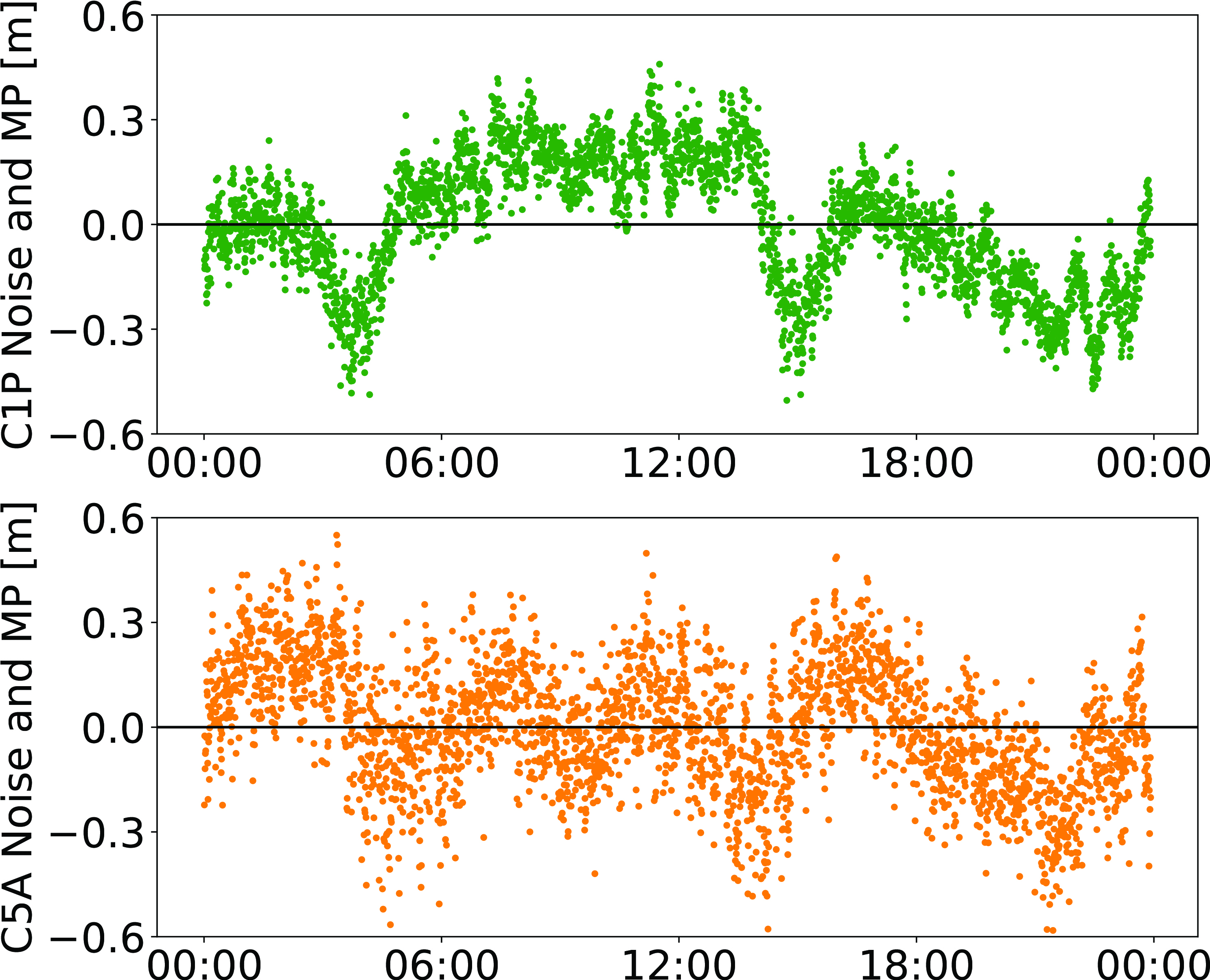
NVS-01 started signal transmission on June 17, 2023, with the pseudo-random noise (PRN) code I10. The satellite’s L1 and L5 signals were tracked by a Septentrio PolaRx5 receiver located in Tokyo, Japan, with a prototype firmware that is capable of tracking the L1 pilot signal. Figure 1 shows the multipath linear combination of NVS-01’s L1 and L5 pilot signals. Whereas the short-term variations are smaller for L1 compared to L5, the overall RMS is 18 cm for both signals.
Figure 1: Noise- and multipath linear combination for NVS-01’s L1 and L5 pilot signals received on 26 June 2023. (Image: All figures provided by the authors)
Whereas IRNSS-1’s rubidium clocks were provided by Spectratime, NVS-01 is the first satellite operating a new type of rubidium atomic frequency standard (RAFS) developed in India. The short-term performance of GNSS satellite clocks can be evaluated with the one-way carrier phase method. The receiver is connected to a highly stable external clock, e.g., a hydrogen maser. Thus, the receiver clock error is negligible. Measurement biases as well as the delays of ionosphere and troposphere on short time scales are removed by fitting a fourth-order polynomial. If no external clock is available, as is the case for the station in Tokyo, the precise clock information can be transferred from another station by a reference satellite jointly tracked by both receivers.
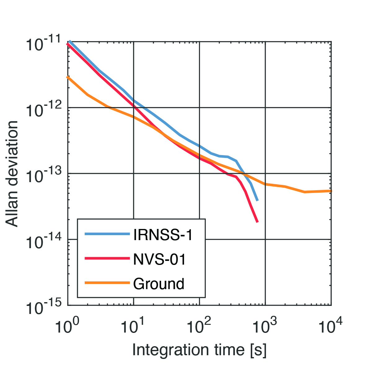
The Allan deviation based on this three-way carrier phase (TWCP) analysis is shown in Figure 2. The hydrogen maser of the IGS station USUD in Usuda, Japan, is used as the reference clock. At short integration times up to 20 s, the Allan deviation computed from the TWCP analysis is dominated by the GNSS measurement noise hiding the true clock performance. Above 20 s, the TWCP demonstrates that the NVS-01’s RAFS stability meets the performance of the ground tests and even exceeds them for longer integration times. At all integration times, the new RAFS outperforms the first generation IRNSS clocks.
Figure 2: IRNSS clock performance obtained from three-way carrier phase analysis as well as ground tests.
Manufacturers
GNSS data used in this article were collected with a Septentrio PolaRx5 receiver.
Peter Steigenberger and Oliver Montenbruck are scientists at the German Space Operations Center of the German Aerospace Center (DLR), where they conduct research in the field of new satellite navigation systems.
Jean‑Marie Sleewaegen is Lead Architect at Septentrio, Belgium, where he has been responsible for GNSS signal processing, system design and technology development since the company’s inception in 1999.
Defense and Security Equipment International (DSEI) in London just wrapped up last week and industry news circulated many reports of various unmanned-related releases and opportunities during the show.
Drawing more than1,500 visitors annually, DSEI is an event at which representatives from governments, armed forces and industry leaders meet to advance the technology of weapons systems. With mostly armed or armored exhibits, the show is aimed at demonstrating to British forces and others coming from around the world, the various advances in weapons-related products and activities — with technological advances taking a primary position throughout the meeting and the exhibit hall.
Some unmanned exhibits/notes of interest
Drone Evolution promoted its UK-built Sentinel tethered UAV and MPU5 mesh radio system that puts a UAV-mounted radio/camera/thermal imaging system more than 150 ft above the ground for up to 6 hr or more — typically to support intelligence gathering, surveillance / reconnaissance, force protection and security. Sentinel is capable of running off of 12 v or 24 v power such as from a field vehicle battery without an inverter or generator, but also through main power, the company states.
Elistair France also launched its Orion 2.2 TE tethered UAV with a 2-in-1 propeller configuration change, which allows it to carry a heavier 5 kg payload. A recently integrated Nextvision Raptor with a 3 km laser rangefinder provides continuous imagery, target tracking, automated object categorization, automated scanning routines, and points of interest for military units, border guards, and national security agencies. Elistair claims its Orion UAV is capable of continuous operations for more than 50 hr over a 328 ft tether.
Robosys Automation and Landau Marine announced a collaboration to convert regular marine vehicles into autonomous unmanned surface vessels (USV). UK’s Robosys provided the Voyager artificial intelligence (AI) vessel system — an autonomy solution using AI combined with decision-aids. These new USVs are capable of surveillance, surveying, warfare, and patrolling duties — Voyager AI is claimed to be vessel-, propulsion-, and sensor-systems agnostic and retrofitting a crewed vessel can result in an autonomous craft operating at speeds of up to 45 kn. The system provides collision avoidance, anti-grounding, smart object avoidance, and autonomous operation during loss of communications.
Orion 2.2 TE – Standard props (left) and with heavy-lift props (right). (Image: Elistair)
Robosys Automation and Landau Marine announced a collaboration to convert regular marine vehicles into autonomous unmanned surface vessels (USV). UK’s Robosys provided the Voyager artificial intelligence (AI) vessel system — an autonomy solution using AI combined with decision-aids. These new USVs are capable of surveillance, surveying, warfare, and patrolling duties — Voyager AI is claimed to be vessel-, propulsion-, and sensor-systems agnostic and retrofitting a crewed vessel can result in an autonomous craft operating at speeds of up to 45 kn. The system provides collision avoidance, anti-grounding, smart object avoidance, and autonomous operation during loss of communications.
Landau Marine USV conversion (Image: Landau)
W Autonomous Systems (WAS)released news of the first landing of an autonomous UAVon the UK Royal Navy’s aircraft carrier Prince of Wales while at sea off Cornwall, England. The WAS HCMC UAV involved has two engines and a twin boom tail and can carry 220lbacross 620 mi and land within 500 ft — about half the length of the landing area on the Price of Wales aircraft carrier. For this trial, the UAV took off from a remote airfield at Royal Naval Air Station Culdrose and flew for 20 min to land autonomously on the deck of the HMS Prince of Wales aircraft carrier.The trials aimed to demonstrate that cargo UAVs are capable of relieving some of the re-supply tasks which are currently carried out by the ship’s helicopters.
BAE Systems and QinetiQ signed an agreement at DSEI to collaborate on autonomous uncrewed air systems (UAS) and mission management systems. Both companies are leading competitive UK aerospace companies, and it’s perhaps unusual to see them collaborating. Perhaps this indicates the degree of importance and complexity that this development investment signifies. The mission management system work will investigate compatibility between BAE Systems and QinetiQ ground-based mission software systems, and develop autonomous systems that enable operator/human decision-makers to combine the use of both manned and unmanned assets on the battlefield. The companies will continue to develop their own airborne vehicles independently but aligned with the intent to continue their collaborative concepts.
HMS Price of Wales leaving Portsmouth UK on its way to rendezvous for the HCMC UAV autonomous deck landing at sea (Image: UK Ministry of Defence)
In summary
This show is huge and this was only a small sample of the sort of unmanned and autonomous news found there this year — tethered UAVs, retrofitting surface vessels to become autonomous USVs, autonomous landings on the Royal Navy aircraft carrier Price of Wales and British industrial collaboration around UAVs.
Last month’s column highlighted GEO-ESCON and how it supported the advancement of the science of geodesy. That said, the National Geodetic Survey (NGS) has been working to improve the National Spatial Reference System (NSRS) by replacing the North American Datum of 1983 (NAD 83) frame and all vertical datums, including the North American Vertical Datum of 1988 (NAVD 88), with four new terrestrial reference frames and a geopotential datum. Many of my previous GPS Worldcolumns have addressed various phases of the project.
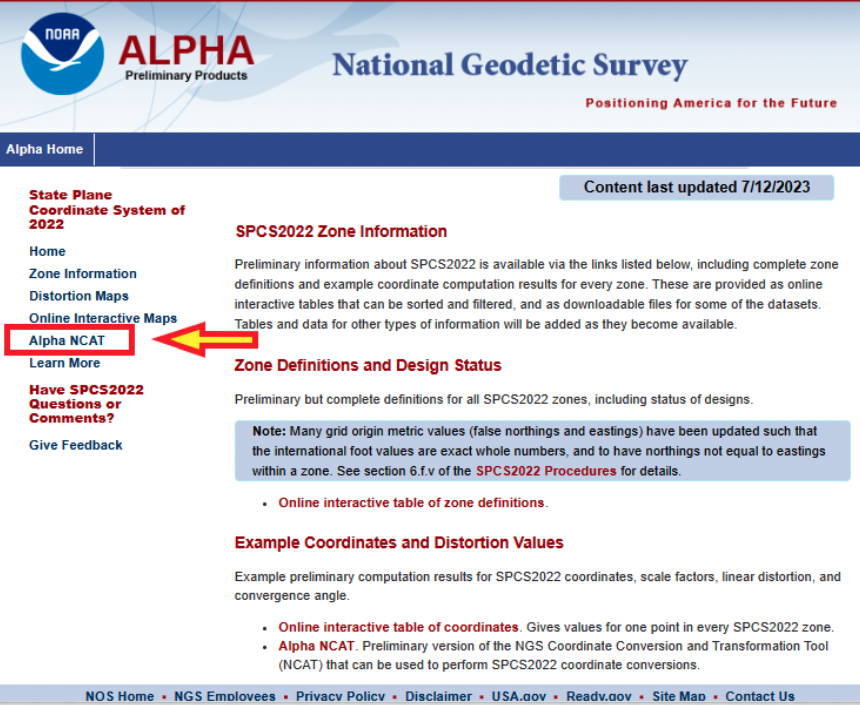
Recently, NGS has developed an Alpha site to enable users to preview preliminary NSRS products and services. I mentioned the Alpha site in my July column, in which I highlighted NGS’s presentations on the new NSRS at the International 2023 FIG Working Week.
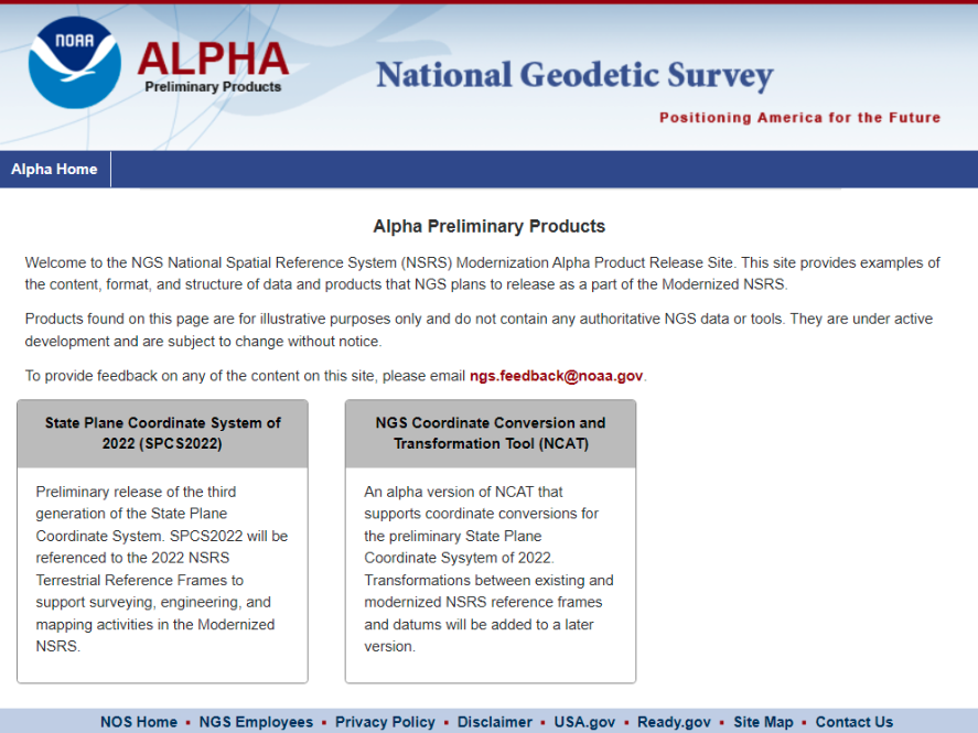
Alpha preliminary products page. (Image: NGS)
The concept of the Alpha site is to provide examples of the content, format, and structure of data and products that NGS plans to release as a part of the modernized NSRS.
NGS highlights that these products are for illustrative purposes only and do not contain any authoritative NGS data or tools. It states that they are under active development and are subject to change without notice.
That said, NGS would like everyone to try the Alpha products and provide feedback to NGS. The first two Alpha products are State Plane Coordinate System of 2022 (SPCS2022) and NGS Coordinate Conversion and Transformation Tool (NCAT). On July 20, NGS held a webinar previewing the Alpha site. Readers can download the powerpoint and video of the presentation here.
Webinar on preview of SPCS2022. (Image: NGS)
As usual, Michael Dennis of NGS did a great job of describing the new SPCS2022, and the differences between the State Plane Coordinate System of 1983 (SPCS83) and SPCS2022. I have included a few of his slides that highlight the SPCS2022.
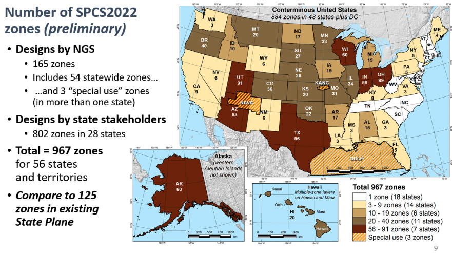
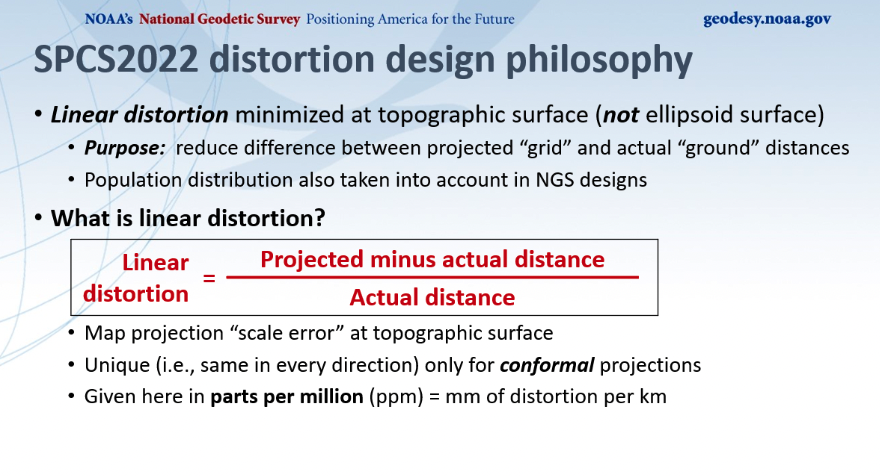
First, SPCS2022 has significantly more zones than the current SPCS83 zones. Second, SPCS83 map projections were designed to minimize linear distortion at ellipsoid surface, whereas the SPCS2022 map projections were designed to minimize linear distortion at topographic surface. The purpose being to reduce the difference between projected “grid” and “actual” ground distances.
Number of SPCS2022 zones. (Image: NGS)Linear distortion of SPCS2022. (Image: NGS)
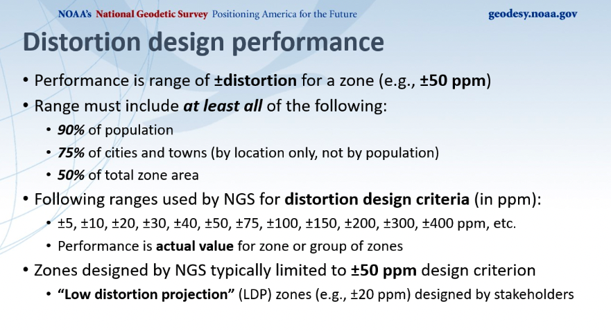
Dennis described NGS’s distortion design performance as seen in the image below. He explained that the performance is a range of +/- distortion for a zone, such as +/-50 ppm. The analysis involved determining parameters where the range includes 90% of the population, 75% of the cities and towns, and 50% of the total area. He highlighted those zones designed by NGS that where typically limited to +/- 50 ppm design criteria, but many low distortion projections (LDP) zones designed by stakeholders consisted of +/- 20 ppm design criteria.
Distortion design performance. (Image: NGS)
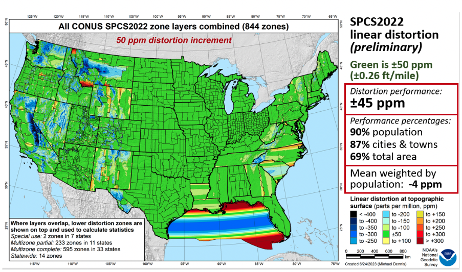
Dennis provided a slide depicting SPCS2022 linear distortion for all CONUS zones with a 50 ppm distortion increment as seen below. As indicated on the slide, green is +/- 50 ppm. The distortion performance is +/- 45 ppm.
All CONUS SPCS2022 zone layers. (Image: NGS)
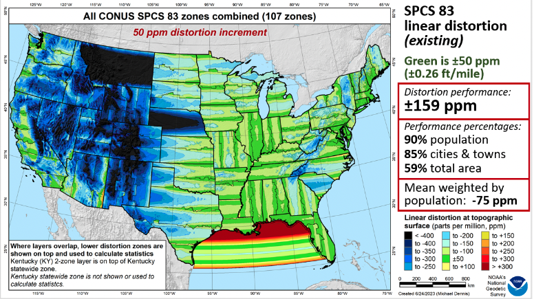
As a comparison to the existing SPCS83 zones, he provided a similar slide for the CONUS SPCS83 zones. See below. As in the previous slide, green represents +/- 50 ppm. The distortion performance is +/- 159 ppm.
All CONUS SPCS83 zone layers. (Image: NGS)
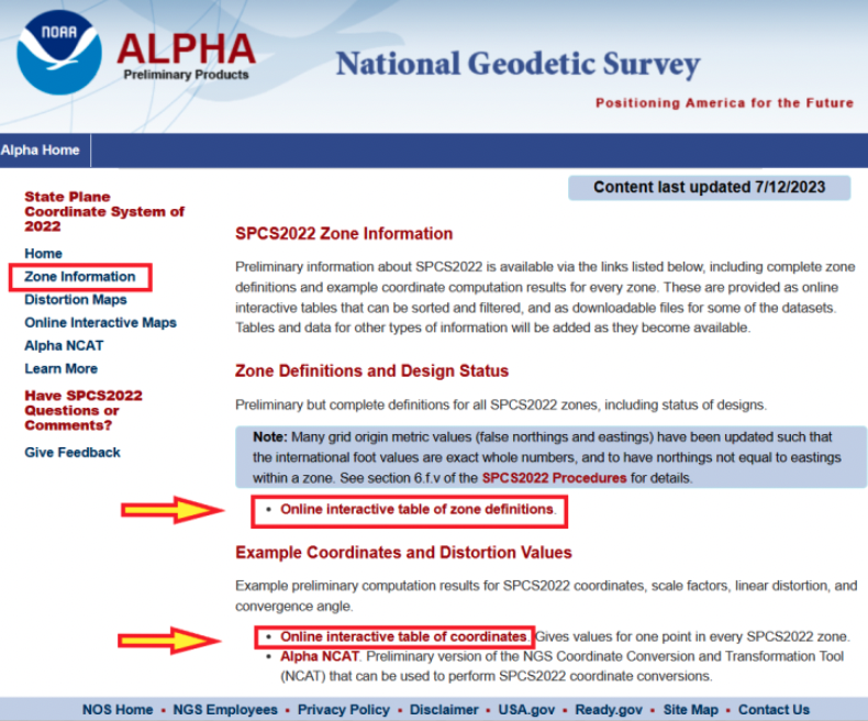
Now, let us look at the Alpha products. First, all zone information can be found here.
SPCS2022 zone information. (Image: NGS)
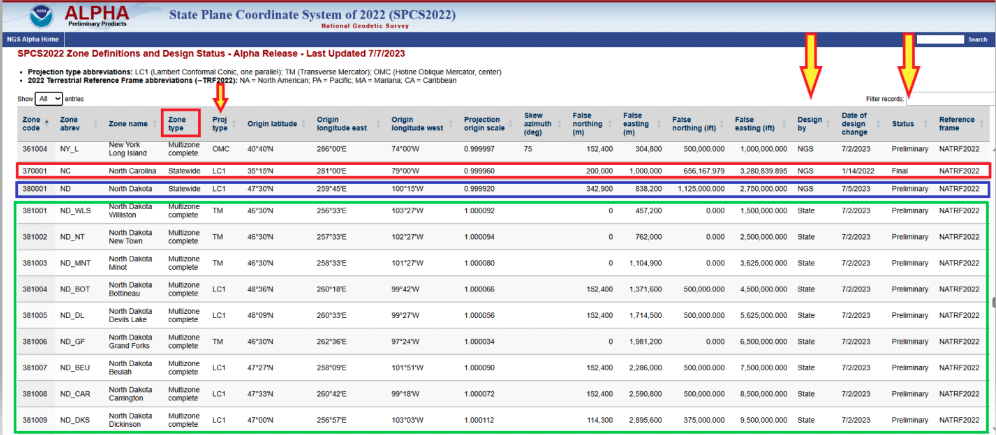
Users can click on the image below for a table of all zone definitions. The table provides the type of projection, if it was designed by NGS or the state, and the zone definition.
Online interactive table of zone definitions. (Image: NGS)
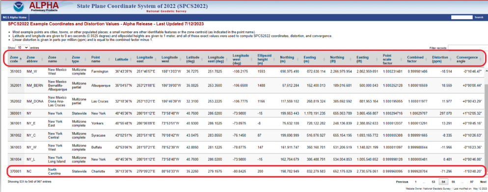
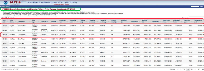
By clicking on the image below, users can obtain information for a point in a particular zone. The table provides northing and easting (meters and feet), scale factor, linear distortion, and convergence angle for a specific coordinate in a particular zone. It should be noted that all values that are provided in feet will be international feet units (ift).
SPCS2022 example of coordinates and distortion values. (Image: NGS)
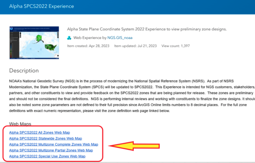
The Alpha page provides an online option to look at all maps. The arrow in the image below highlights the link to access the online interactive maps.
Alpha page for SPCS2022. (Image: NGS)
When users click the link on the page, they are directed to an ArcGIS NOAA web map viewer.
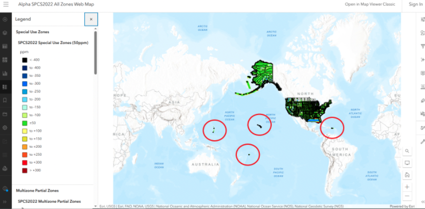
Alpha SPCS2022 experience. (Image: NGS)
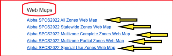
To access the online map function, users need to click one of the Alpha SPCS2022 zone options.
Alpha web maps. (Image: NGS)
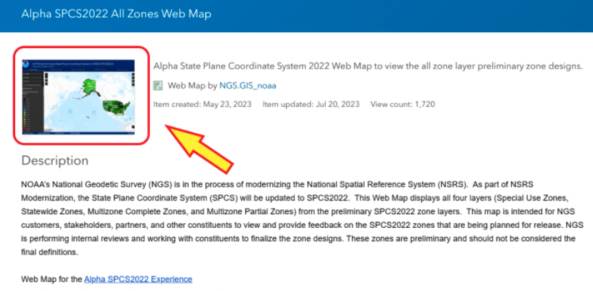
Once users click on one of the web map buttons, another map page with a map icon appears on which userswill need to click to get to the map of zones.
Alpha SPCS2022 all zone web map. (Image: NGS)
After users click on the map icon, they will get another web page that contains the map zones based on their selection. In my example, I selected “all zone web map.” Once users get to this page, they can zoom into any area to find a particular zone.
All zone web map. (Image: NGS)
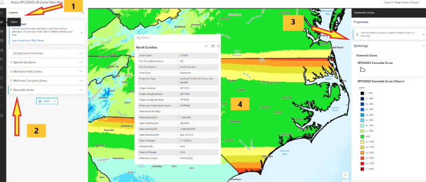
I zoomed down until I located North Carolina’s map zone. The web page provides access to various layers and information. First, if users move their curser over the layer button, a list of layers pops up. Next, select one of the layers, such as Statewide Zones, then the properties of the map are placed on the map. Finally, when readers click on the map itself, the information about the SPCS2022 zone appears on the map.
Alpha North Carolina Statewide Zone web map. (Image: NGS)
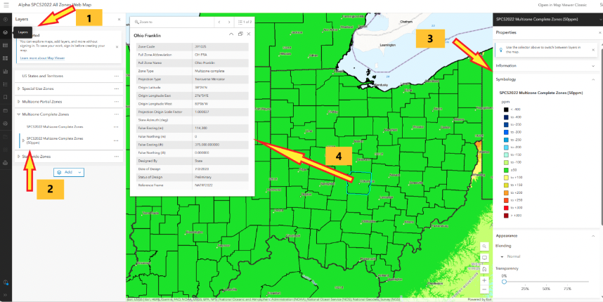
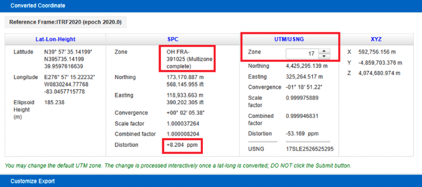
North Carolina is a state that elected to have a single statewide zone. Some states decided to design several LDPs that cover certain areas or cover the entire state. Ohio is a state that designed 89 LDPs that cover the entire state. Again, by selecting the layer button, users have an option to select multizone complete zones, the properties appear on the map, and finally clicking on the map provides the zone information for that zone. In this example, I clicked on Columbus, Ohio, which is in the Ohio Franklin Zone.
Alpha Ohio multizone complete zones web map. (Image: NGS)
Users can obtain specific information for a coordinate located in the Ohio Franklin Zone by clicking on the online interactive table of coordinates. Note that the distortion is 6.725 ppm at the coordinate in the zone.As previously stated, this was a user–defined LDP zone.
SPCS2022 example of coordinates and distortion values in Ohio Franklin Zone. (Image: NGS)
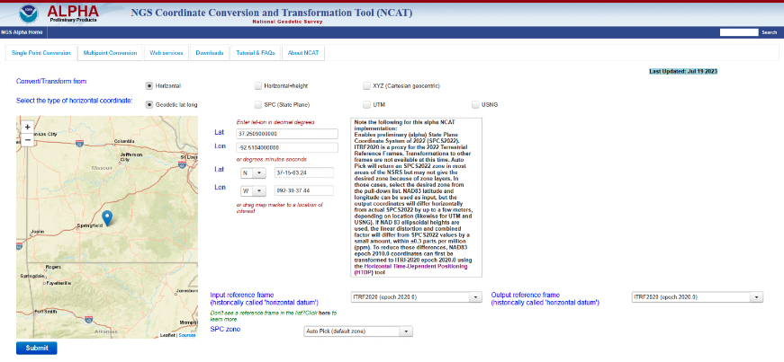
Another Alpha site available for users to evaluate is the NGS Coordinate Conversion and Transformation Tool (NCAT). NCAT is probably the tool that most surveyors will be interested in using and providing feedback to NGS. Users can access NCAT on the Alpha SPCS2022 webpage or by clicking here.
The Alpha NCAT website has a note about the coordinates that users should provide as input to the routine. The bottom line is that the input coordinates need to be in ITRF2020 (epoch 2020.0), or readers may not get their desired zone. NGS recommends that users convert the coordinates to ITRF2020 (epoch 2020.0) using the Horizontal Time-Dependent Positioning (HTDP) tool.
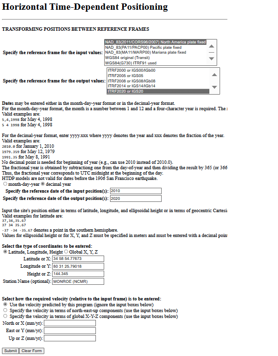
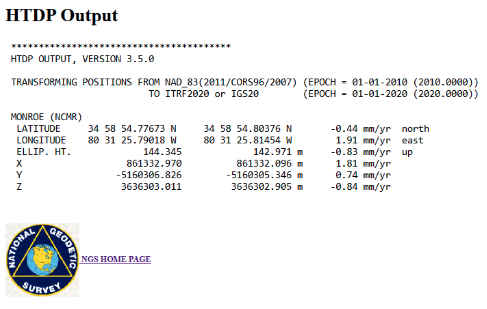
Users can access HTDP here. I provided an example of HTDP for a CORS in North Carolina. I used the NAD 83 (2011) [epoch 2010.0] published coordinates of the CORS as my input values.
Example of a HTDP computation. (Image: NGS)Output of a HTDP computation. (Image: NGS website)
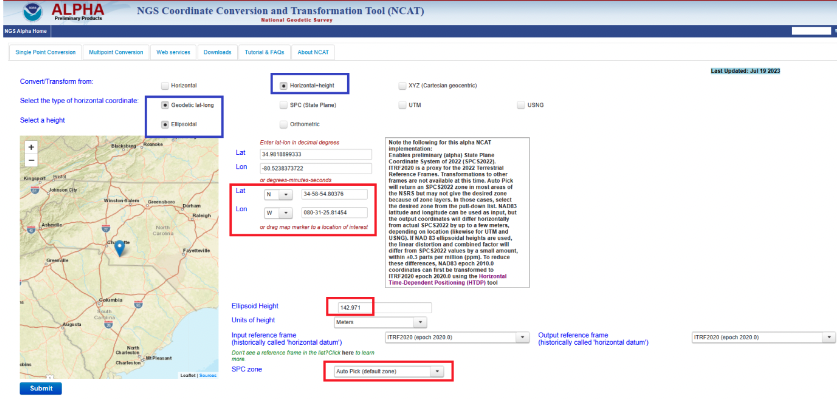
After using HTDP to transform the coordinates from NAD 83 (2011) to ITRF2020, I used the Alpha NCAT tool to compute the SPCS2022 values for the mark. I provided an example of the Alpha NCAT routine using the coordinates of the North Carolina CORS NCMR. The program defaults to horizontal only, so I changed it to the horizontal-height option. The user then enters the latitude, longitude, and height of the mark. Lastly, the user has an option to select the SPC zone or the program will select the zone based on the coordinates of the mark. In my example, I selected the auto pick option.
NCAT input for MONROE CORS (NCMR). (Image: NGS)
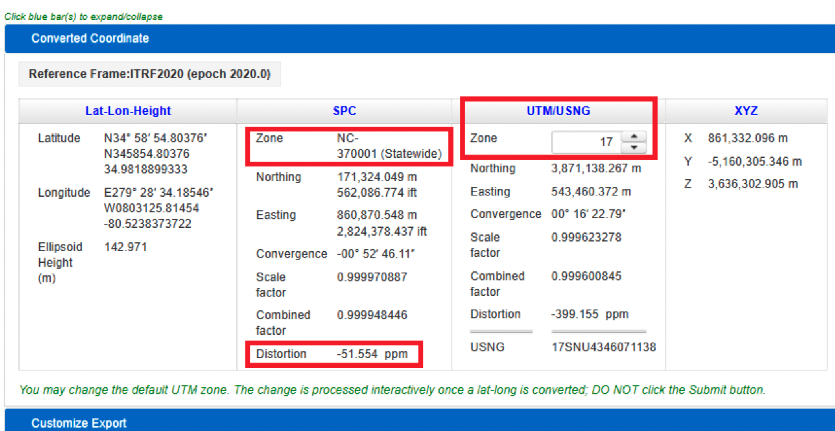
The image below provides the output of NCAT. I have highlighted a few items in the image. First, the program selected North Carolina’s Statewide Zone, the distortion is -54.554 ppm at this mark, and the UTM zone selected is Zone 17. The output also provides the scale and combined factors.
NCAT output for NCMR. (Image: NGS)
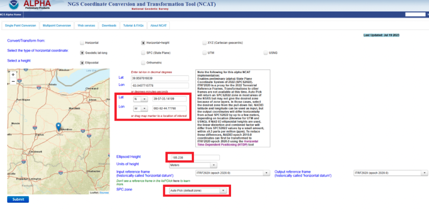
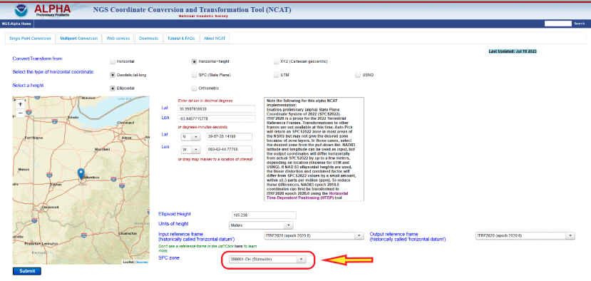
North Carolina is a state that elected to have a single statewide zone, but, as previously mentioned, some states decided to design their own LDPs. Again, Ohio is a state that designed LDPs that cover the entire state. Once again, I entered the coordinates into the input boxes and selected the auto pick (default zone) option. As indicated in the converted coordinates section, the program selected the OH FRA-391025 zone based on the coordinates of the mark. Notice that the distortion is only +8.024 ppm.
NCAT results for Columbus CORS (COLB). (Image) NGS)
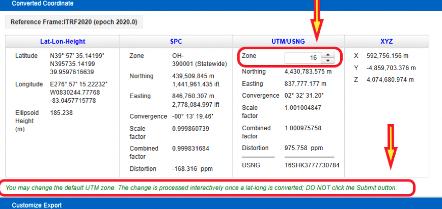
The user has the option to select a different zone than the default zone. The image below provides the SPC values for the COLB mark when selecting the Ohio Statewide Zone. Notice that the distortion value changes from +8.024 ppm to -168.316 ppm. Also, as expected, the UTM and X, Y, and Z values have not changed.
NCAT results for COLB selecting Statewide Zone. (Image: NGS)
One last option to highlight is that the user can change the default UTM zone by clicking on the up or down arrows under the UTM column. In my example, I changed the UTM zone from 17 to 16. Obviously, the values under the UTM column changed.
Option to change default UTM zone. (Image: NGS)
The concept of the NGS’s Alpha site is to provide examples of the content, format, and structure of data and products that NGS plans to release as part of the modernized NSRS. NGS states that these Alpha products are for illustrative purposes only and do not contain any authoritative NGS data or tools. It states that they are under active development and are subject to change without notice.
That said, NGS would like everyone to try these Alpha products and provide feedback to NGS, so that they can improve their products and services. I would encourage readers to try these Alpha sites and provide comments and suggestions to NGS.
In 1973, on March 1, Xerox launched the Alto, the first computer designed from its inception to support an operating system based on a graphical user interface; on April 3, Martin Cooper of Motorola made the first cellphone call, from 6th Avenue in New York City; and TCP, Ethernet, and fiber optics were created.
That same year, over Labor Day weekend, a dozen people in a small conference room on the top floor of a nearly deserted Pentagon, at a meeting called and chaired by Brad Parkinson that became known as “Lonely Halls,” made the key design choices for the Global Positioning System. None of those fundamentals have changed in the intervening half century, during which GPS was developed, launched, and modernized and became a worldwide utility underpinning many critical economic sectors — including precision agriculture, financial services, location-based services, mining, surveying and telecommunications.
At the time, Parkinson — a United States Air Force colonel with a Ph.D. in astronautical engineering from Stanford University, three years of experience in inertial guidance, and 26 combat missions in AC-130 gunships — was the first director of the GPS Joint Program Office in Los Angeles. As he and his co-authors recalled in a detailed two-part history of GPS (see the May and June 2010 issues of GPS World), the aspects of GPS that were defined at Lonely Halls included:
Simultaneous passive ranging to four satellites in inclined orbits, ensuring user equipment would not require a synchronized atomic clock.
A signal structure using CDMA modulation, including both a precision military code and a clear acquisition one that would be freely available to civil users worldwide.
Two GPS broadcast frequencies in the L band.
A family of user equipment prototypes, including a low-cost set that would demonstrate civilian use.
I recently asked Parkinson how GPS today differs from the design that came out of the Lonely Halls meeting. “The fundamental answer is that it’s identical,” he said, “in terms of design, the atomic clock, the CDMA signal, and four satellites to eliminate the need for a user clock. What has been evolving, of course, is that we’ve added another frequency and several new signals, including those for the military and L1C.”
From the very beginning, Parkinson encouraged civilians to use the system, correctly predicting that “they would apply their research and design talents to drive the size, weight and power requirements of the receivers down and the family of applications up,” he said. “That’s exactly what happened, in my opinion.”
Which applications surprised him the most? “Our revolution has been enabled by the advent of integrated circuits in terms of size and cost,” he said. For example, RTK has now given dynamic users access to centimeter accuracies.
“We were driven by visions of the many beneficial applications of GPS; visions that were not yet shared by the Air Force. GPS is a testimony to my team’s engineering competency, their tenacity, and their resourcefulness. I, and the whole world, owe them a large debt for the benevolent revolution they created.”
Two recent announcements showed China’s progress establishing its national “High-Precision Ground-based Timing System.” Some verbiage in the most recent announcement could indicate that the system is nearing completion.
The timing system is designed to support a vast array of scientific and technological applications as well as provide services when space-based signals are not available.
According to some Western observers, it is another example of China’s increasing lead over the United States in positioning, navigation, and timing (PNT) technology.
Completion of the terrestrial system could have even more troubling implications for the United States.
Recent Announcements
On May 21 this year, a government affairs article in Shaanxi’s “The Paper” announced accelerated construction in Xi’an of a science center. Its centerpiece will be the country’s High-precision Ground-based Timing System. It is not entirely clear from the article whether this site will be the engineering and administrative headquarters for the system, or one of several “timing stations.”
The article also says the national system will be the largest in the world — with more than 20,000 kilometers of optical fiber and 295 time and frequency transmission sites — and will integrate space- and ground-based signals.
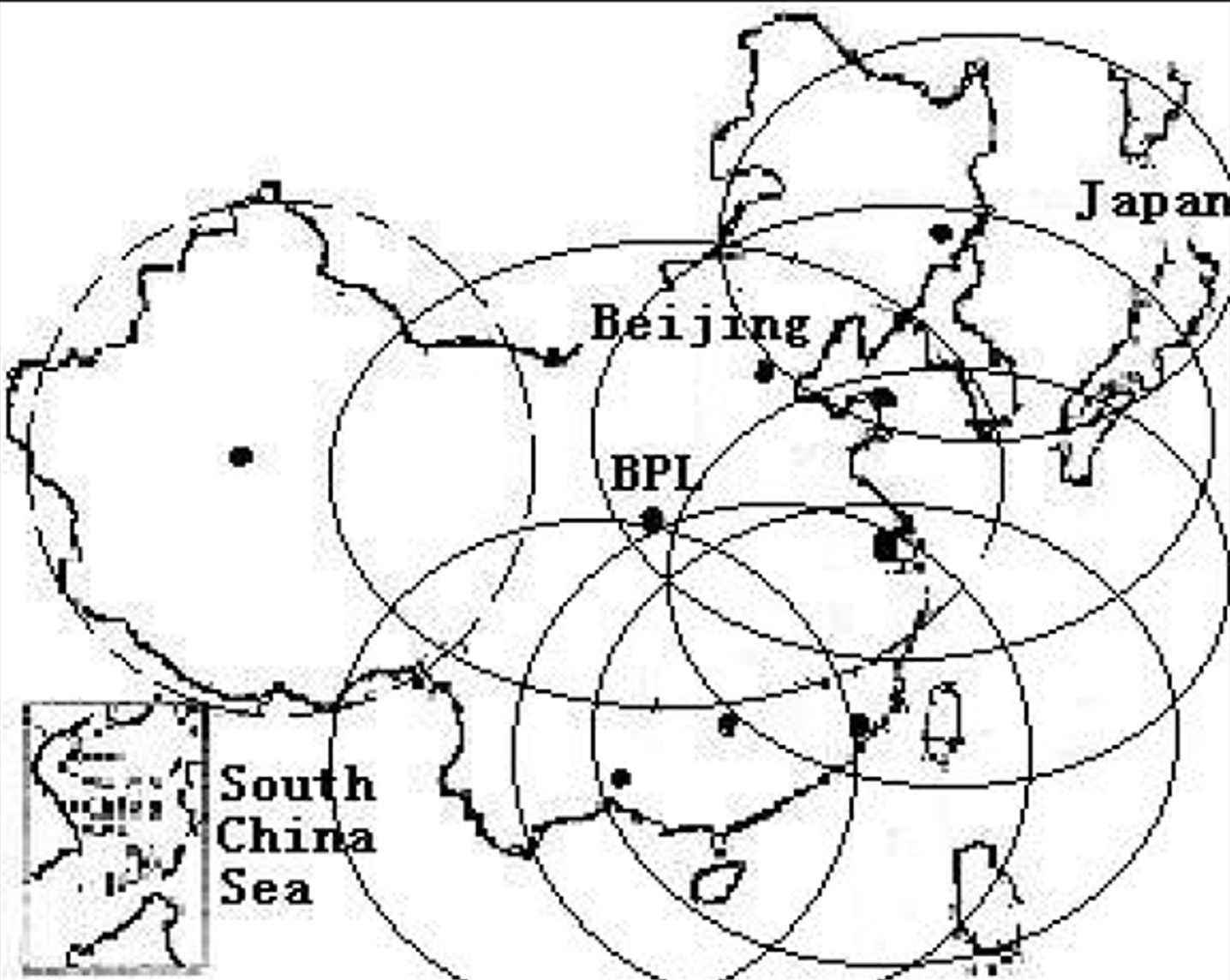
The network, according to the article, will supplement and improve the new eLoran (sometimes mistranslated by software as “Roland”) system in the western portion of the country. It will also support legacy eLoran “long-wave” signals in the east ensuring that the entire nation is well served.
Graphic from 2014 Chinese Academy of Sciences paper on Laron showing projected coverage in the western part of the country. Subsequent papers and announcements have indicated that western part of the network is complete or soon will be. (Image: Chinese Academy of Sciences)
Accuracy for the system’s fiber-optic transmissions is claimed to be less than 100 pico-seconds, with differential eLoran at less than 100 nanoseconds.
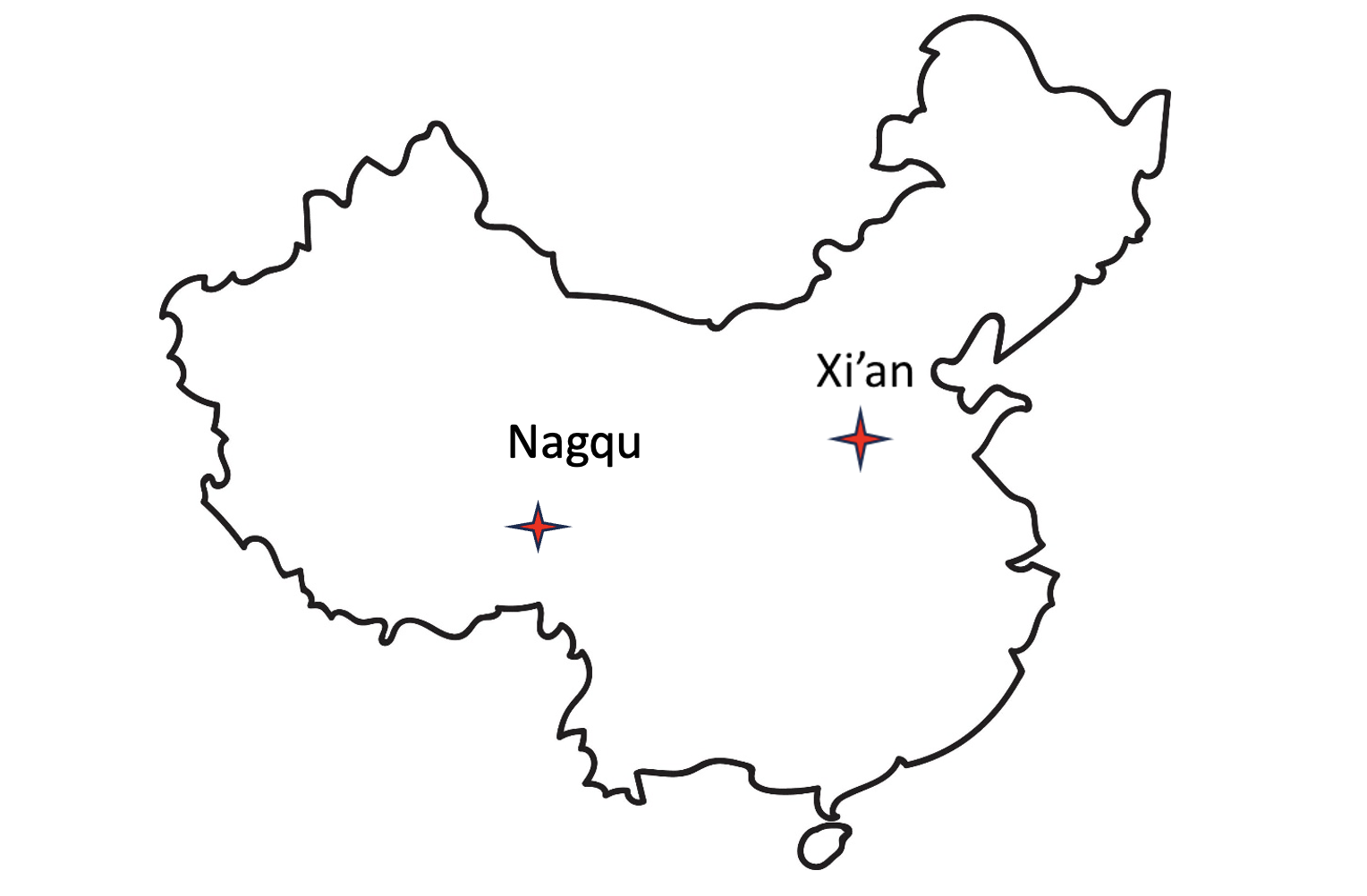
Construction recently announced in Xi’an and Nagqu as part of China’s High-precision Ground-based Timing System.
A much shorter press release was issued on June 8, announcing groundbreaking for a “timing station” in Nagqu on the Tibetan plateau in China’s west. The announcement said that, once the station was complete, China will “…realize national soil coverage of long-wave [eLoran] timing signals…”
Expansion of its eLoran and fiber infrastructure to serve the entire nation gives China what some have called the “PNT resilience triad” — signals from space, from terrestrial broadcast, and over fiber. The three sources of delivery are sufficiently different that an accidental or malicious disruption of one is highly unlikely to impact the other ones. Users accessing all three should experience minimal to no impact.
Both the May and June announcements said that finishing the timing project will benefit China’s national economy and national security.
Timing is essential tech infrastructure. More precise and robust timing enables improvements to current applications and the creation of new ones. For example, better timing can enable greater spectrum efficiency with more throughput on existing frequency bands. Highly precise fiber-based timing could also support using 5G telecommunications networks for hyper-precise positioning in autonomy corridors serving self-driving vehicles, UAVs, and other systems.
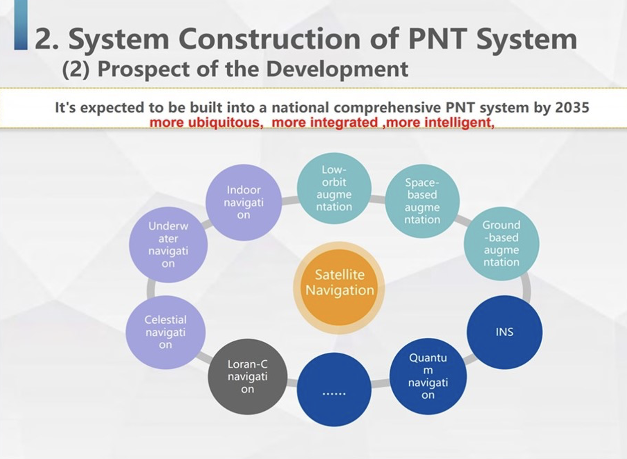
China’s ground-based timing system is part of a larger plan by its National Timing Service Center for a system of systems approach to PNT. Described as a “comprehensive approach” at the Standford PNT Symposium in 2019, the architecture has satellite-based navigation at its heart and includes a wide variety of other capabilities.
Graphic showing China’s plan for multiple, mutually supporting, diverse methods of positioning, navigation, and timing service and data. (Presentation by China’s National Time Service Center at 2019 Standford PNT Symposium)
Some observers trace China’s national PNT efforts to an incident in 1996 during the Third Taiwan Strait Crisis. Chinese forces fired three missiles toward a point in the sea offshore of Tiawan’s Kee Lung naval base. Two of the missiles were lost. According to the People’s Liberation Army this was because the United States denied or altered GPS signals that the missiles were using for guidance.
Known by China’s military as “The Unforgettable Humiliation” the incident sparked decades of effort to ensure China would never again be dependent upon another nation or space for PNT. The BeiDou global navigation satellite system and the High-precision Gound-based Timing System are the two most noteworthy accomplishments in this regard.
Implications for the United States
China’s ever-increasing lead in essential PNT technology and infrastructure is of great concern to many in the United States.
China’s global navigation satellite system, Bei Dou, is newer and, according to a presidential advisory board, substantially superior to GPS in many ways. Using it as an instrument of “soft power,” China is offering other nations BeiDou signals, along with discounted user and support equipment, as part of its Belt and Road, and Digital Silk Road initiatives. Where successful, these efforts erode both GPS usage and U.S. influence.
Of greater concern to many are the “hard power” implications of China’s PNT dominance.
While China has and continues to develop multiple and resilient sources of PNT, in the United States “GPS is still a single point of failure,” according to a member of the National Security Council.
As a result, if China were to interfere with GPS in some way, a U.S. response in-kind against BeiDou would have much less impact. This strategic asymmetry has been described by former CIA senior analyst George Beebe as “an open invitation” for mischief or attack. One that could easily lead to an escalating series of responses ending in an armed conflict no one wants.
At a more tactical level, China’s eLoran system extends 1,000 miles offshore covering Taiwan, the Strait, and all approaches. In a conflict to capture the island and make it subject to the Communist regime, China could block all signals from space while preserving its forces’ ability to maneuver and communicate. Already at a disadvantage having to deploy far from their support bases, this would further hamper U.S., Japanese, and other forces hoping to help Taiwan maintain its independence.
The U.S. Department of Defense boasts it can operate well in GPS-denied environments and says it is also working on alternative means of navigation for deployed forces.
This begs the strategic question, though, of whether the United States would be willing to come to the aid of Taiwan or another ally if the homeland were threatened with a prolonged and crippling disruption of GPS services.
Prior to Russia’s invasion of Ukraine, the Kremlin destroyed a defunct satellite and boasted it would shoot down all 32 GPS satellites and “blind NATO” if the alliance intervened. Many observers have wondered whether that has played into subsequent U.S. and NATO policy toward the conflict.
Unfortunately, little has been done to eliminate the possibility of a belligerent adversary holding the U.S. homeland hostage through GPS.
For two decades narrow government and industry interests in GPS production have successfully opposed any effort they see as possibly “competing” for space in limited budgets. Appeals that such projects would increase system security by “taking the bullseye off” GPS satellites and signals have been to no avail.
However, this may be changing. Several years ago the National Guard began development of a national timing architecture and network, called NITRO. The project supports the Guard’s own requirements to be able to operate without GPS and to aid state first responders. It is already in use in 7 states.
The future of NITRO is unclear, though, as the Department of Defense sees it as a civil defense rather than a national defense project and is no longer supporting it in the budget. Yet, the National Guard’s funding flows through defense appropriations.
As of this writing, the National Guard and NITRO remain stuck in a bureaucratic and budgetary no-man’s land with no clear path forward.
“When Galileo was just an idea, its EU proponents used the argument of “political, economic, social and technological sovereignty.” Should countries such as Brazil build their own GNSS constellations?”
Ismael Colomina
“When, almost 20 years ago, I was in Brazil giving talks about the future of Galileo and promoting its combined use with GPS, I was often asked the logical question as the EU Galileo sovereignty arguments were known. It is not for us Europeans to answer that question for other countries or oppose their plans. However, while being aware of the defense aspects of GNSS, we may ask ourselves whether an international cooperative approach could avoid a somewhat unjustified future proliferation of GNSS constellations.”
“GPS enables continuous access, free of fees and political encumbrances. A decision by any nation to bear the cost of creating a separate GNSS should be justified by realistic requirements for security or coverage that cannot be satisfied by GPS. Japan, South Korea and India are models for additional GNSS services driven by regional needs. For any new system, compatibility with other GNSS, as well as life-cycle costs, are the primary factors to consider.”
“When Galileo was just an idea, the U.S. military’s GPS was the only viable global constellation. GLONASS was a rusting cold-war relic and BeiDou was in an embryonic stage. The U.S. military’s official policy was that any civilian use was not guaranteed and could be interrupted anytime. Therefore, no nation outside of the United States could depend on GPS and maintain its independent interests. However, today, any country could reasonably maintain its sovereignty by ensuring interoperability with all four — betting that at least one of those constellations would always be available to them. They don’t need their own system.”
“Those are always nice-sounding words when trying to justify a monumentally huge expense. However, is there an actual need to justify that expense? Can the expense and burden of perpetual system operation and maintenance, along with technological innovation to keep pace with other systems and user requirements, be guaranteed over the long term? For the users, GPS can be seen as the gift that keeps on giving, whereas to the operators it is the gift that keeps on costing. So, do Brazil, or other nations, have the commercial or social need, technological foundation, economic resources and political will to initiate a new system and sustain it over the long term? Providing a GNSS constellation is not for the faint of heart or those of short-term vision.
“It has been no secret — there are vulnerabilities within the timing and synchronization platforms used by the energy sector,” according to David Wells. Citing well recognized vulnerabilities associated with using signals from GPS, Wells said “…a secure, verifiable, and reliable solution is paramount.”
CAST’s mission is to research, establish and demonstrate best practices for timing within electrical grids.
As part of its efforts, DOE and the Oak Ridge team recently published “Implementing a Terrestrial Timing Solution: Best Practices.” The document is an important complement to the model network CAST has established to demonstrate practices and do further research.
Best practices in the document include discussion of:
equipment needed
various timing sources and transfer methods
the need for environmental stability
IEEE 1588 Precision Time Protocol
hardware recommendations.
Implementing these best practices and establishing timing networks will be up to grid operators as encouraged by DOE’s Power Marketing Administrations.
Others are already taking notice, though.
Concerned about their ability to maintain land mobile radio networks and other applications when GPS is denied or manipulated, the National Guard, in coordination with Homeland Security advisors and emergency managers, has implemented its own terrestrial timing network across the states and territories. The project, Nationwide Integration of Timing Resiliency for Operations (NITRO), has already been implemented in seven states. Major General William Crane, adjutant general for West Virginia, said that NITRO and CAST are well aligned, and the NITRO team will be working with DOE to ensure that continues to be the case going forward.
Pat Diamond, a member of the President’s Space-based Positioning, Navigation, and Timing Advisory Board and a former consultant to CAST, contributed to the development of the best practices. He is also an on-going participant in timing forums such as the ATIS Sync Committee.
When asked for his view he replied “The CAST best practices lay out the how wide area time synchronization networks should be deployed. There needs to be a concerted effort for DOE jointly with the power generating industry to actually implement an end-to-end time synchronization network demonstrating that these best practices are cost effective, manageable and implementable to solve the technical limitations of GPS dependence within a power generating marketplace.”