Hurricane Patricia — “Extremely Dangerous” Category 5 Hurricane — Is the Strongest Storm Ever Recorded.
Esri is providing a continuously updated hurricane map that shows the projected paths, storm surge, weather warnings and precipitation of Hurricane Patricia, the “strongest hurricane ever recorded.” In addition, the real-time effects of the storm can be seen via social media posts. The website, Hurricanes & Cyclones, is part of the Esri Disaster Response Program.
Hurricane Patricia became the most powerful tropical cyclone ever measured in the Western Hemisphere on Friday morning as its maximum sustained winds reached an unprecedented 200 mph (320 kph).
The National Oceanic and Atmospheric Administration (NOAA) is offering updates through its National Hurricane Center (NHC).
Hurricane Patricia is heading toward Mexico’s west coast, and is expected to make landfall near Puerto Vallarta. “Confidence is high that Patricia will make landfall in the hurricane warning area along the coast of Mexico as an extremely dangerous category 5 hurricane this afternoon or evening,” according to a Friday morning forecast discussion from the National Hurricane Center.
It will then cause massive rainfall in Texas after it hits landfall. “The global models continue to depict the development of a cyclone near the Texas coast over the weekend. This system should be non-tropical in nature. However, this cyclone is expected to draw significant amounts of moisture from Patricia’s remnants, and could result in locally heavy rainfall over portions of the northwestern Gulf of Mexico coastal area within the next few days,” according to the NHC discussion.
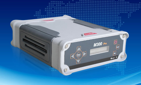
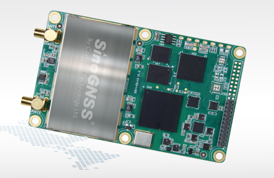
ComNav has released the M300 Pro, a CORS GNSS receiver, and the K528G, a new GNSS OEM board for heading.
Designed for reference stations, the M300 Pro tracks GPS, GLONASS and Beidou (B1, B2, B3), and will track Galileo, QZSS and other coming constellations. Its web server function enables easy and convenient remote control. The M300 Pro is compatible with many kinds of CORS software, using the standard data format RTCM and the various data transfer protocols such as UDP, TCP and Ntrip.
Raw GNSS observation data can be saved in Rinex format and remotely downloaded. The M300 Pro contains multiple ports, which can configure and connect with external sensors, including but not limited to meteorological sensors, barographs and inclinometers. The PPS output function provides a guarantee for precision timing. The M300 Pro also has the functionality of event mark and external memory.
The K528G GNSS board.
The K528G is a dual-frequency and multiple constellations GNSS board that provides the highest accuracy in differential positioning. K528G benefits from plenty of constellations signals, due to its advanced tracking performance of both GPS and GLONASS. The K528G can provide positioning and heading information generated by two antennas.
The K528G is designed for guiding and positioning construction engines, dredges, barges, shipping container cranes, mining equipment and intelligent transportation systems.
PrecisionHawk will serve as a technical resource to regulators. (PRNewsFoto/PrecisionHawk)
PrecisionHawk is contributing to a safety task force created by the U.S. Department of Transportation and the FAA. The task force brings together a diverse group, representing the UAS and manned aviation industries, the federal government, and other stakeholders, to develop an augmented registration process for Unmanned Aircraft Systems.
“PrecisionHawk is working on many safety solutions, procedural and technological, that we believe can contribute to safer operations for commercial drones in the national airspace,” said Ernest Earon, PrecisionHawk CTO and co-founder. “The creation of this task force further demonstrates the willingness of the FAA to move forward with industry leaders to promote rapid and safe integration.”
“As a UAS technology company and operator, we know how important coordinated identification is to the environments in which we work,” said Thomas Haun, VP of Strategy at PrecisionHawk. “The goal of this task force, to create a streamlined registration process for UAS, will have a direct and positive impact on the operations of our partners and service teams.”
“This task force presents another opportunity for PrecisionHawk to serve as a technical resource to regulators as we move towards the adoption of UAV regulations. Earlier this year PrecisionHawk was also named, alongside CNN and BNSF, to the FAA Pathfinder Program to test and develop technology solutions to solve beyond line of sight operations,” PrecisionHawk said in a statement.
New Task Force to Develop Recommendations by Nov. 20
WASHINGTON — U.S. Transportation Secretary Anthony Foxx and FAA Administrator Michael Huerta today announced the creation of a task force to develop recommendations for a registration process for Unmanned Aircraft Systems (UAS).
The task force will be composed of 25 to 30 diverse representatives from the UAS and manned aviation industries, the federal government and other stakeholders. The group will advise the department on which aircraft should be exempt from registration due to a low safety risk, including toys and certain other small UAS. The task force also will explore options for a streamlined system that would make registration less burdensome for commercial UAS operators.
The task force may make additional safety recommendations as it deems appropriate. Secretary Foxx directed the group to deliver its report by Nov. 20.
“Registering unmanned aircraft will help build a culture of accountability and responsibility, especially with new users who have no experience operating in the U.S. aviation system,” Foxx said. “It will help protect public safety in the air and on the ground.”
Every day, the FAA receives reports of potentially unsafe UAS operations. Pilot sightings of UAS doubled between 2014 and 2015. The reports ranged from incidents at major sporting events and flights near manned aircraft, to interference with wildfire operations.
“These reports signal a troubling trend,” Huerta said. “Registration will help make sure that operators know the rules and remain accountable to the public for flying their unmanned aircraft responsibly. When they don’t fly safely, they’ll know there will be consequences.”
While the task force does its work, the FAA will continue its aggressive education and outreach efforts, including the Know Before You Fly campaign and No Drone Zone initiatives with the nation’s busiest airports. The agency also will continue to take strong enforcement action against egregious violators. At the same time, it will continue working with stakeholders to improve safety to ensure further integration and innovation in this promising segment of aviation.
Secretary Foxx was joined by representatives from the following stakeholder groups:
UPDATE: Read news of the official announcement here.
The federal government is expected to announce today a new plan requiring anyone buying a drone to register the device with the U.S. Department of Transportation. The registration of the drone will enable authorities to track a drone back to its owner if used in a dangerous manner.
Under the plan, the DOT would work with the drone industry to set up a structure for registering the drones, and the regulations could be in place by Christmas.
The government has been concerned about the rise in close calls between unmanned drones and aircraft flying into and out of some of the nation’s biggest airports. In July, a passenger jet preparing to land at New York’s John F. Kennedy International Airport had a close call with a drone, which was 100 feet away from the jet at an altitude of 1,700 feet. Normal safe separation distance is between aircraft is at least 1,000 feet.
Private drones were also blamed for hampering aerial firefighting efforts over a California blaze in July. Firefighting aircraft trying to attack the fast-moving blaze in the Cajon Pass had to leave the area for around 20 minutes over safety concerns, officials said. That fire swept over a freeway and burned 20 vehicles.
On Oct. 6, the FAA announced the largest civil penalty proposed yet — $1.9 million — against a UAS operator for endangering the safety of the national airspace.
Brian Wynne, president & CEO of the Association for Unmanned Vehicle Systems International (AUVSI), released the following statement on today’s announcement that he is joining the U.S. Department of Transportation’s Task Force to develop a streamlined registration process for unmanned aircraft systems (UAS):
“AUVSI welcomes the opportunity to join this task force of government and industry stakeholders. This collaborative effort to develop an efficient process for UAS registration should lead to increased accountability across the entire aviation community.
“Under the FAA’s proposed small UAS rules released earlier this year, commercial operators would be required to register their platforms. Extending this requirement to other UAS users will help promote responsibility and safety.
“In addition to UAS registration, it is essential for the FAA to finalize its small UAS rules as quickly as possible. Once this happens, we will have an established framework for UAS operations, allowing anyone who follows the rules to fly. Considering that safety is at stake, time is of the essence to finalize the rules.
“Because safe operations are essential for all users of the national airspace, AUVSI is also looking forward to continuing its work with the FAA, the Academy of Model Aeronautics and more than two dozen supporters of the ‘Know Before You Fly’ campaign to educate newcomers to UAS technology about safe and responsible flying.”
Data is curated by SpecOut.com and sourced from the Center for the Study of the Drone at Bard College.
According to UrsaNav Inc., the Wildwood, NJ eLoran transmitter will be continuously broadcasting from 0900 (EST) on 21 October 2016 through 1200 (EST) on 22 November 2016. Wildwood will be broadcasting as 8970 Master and Secondary most of the time but occasionally may operate at other rates.
The team will evaluate eLoran as a potential complementary system to GPS. The capabilities and potential utilization methods of eLoran will be explored in depth to identify all strengths, capacities, and potential vulnerabilities of the technology.
The sites are the legacy ground-based radio navigation infrastructure of the decommissioned Loran-C service that could be retained and upgraded to provide eLoran low frequency service.
Under the CRADA, Exelis will use the former Loran-C assets to put eLoran signals in space for research, test and demonstration of the ability of eLoran to meet precise positioning, navigation and timing (PNT) requirements of government and privately-owned critical infrastructure.
The first station Exelis is broadcasting from is in Wildwood, N.J. The broadcasts will provide a usable signal at a range up to 1,000 miles.
Timing experts will share their views on timing and synchronization at GPS World’s next seminar, scheduled for Thursday, Oct. 29. Registration is free for “Timing, Time Transfer and Synchronization: New Applications and Techniques,” a GPS World Market Insights webinar sponsored by EndRun Technologies.
In the webinar, an expert panel will discuss the current efforts behind — and changing demands to — keeping the nation’s timekeeping and synchronization infrastructure up to speed. The speakers will examine why timing has become more critical than ever for the Internet of (Every)thing and the nation’s economy.
The panel will also shed light on cutting-edge time transfer research, and dive into new applications and techniques for use in metrology, defense, communications and aerospace. In the closing Q&A period, participants will have the chance to receive expert answers to synchronization questions.
This webinar event will be good preparation for those planning to attend ION’s Precise Time and Time Interval (PTTI) Meeting in January — and for those who can’t make it. Watch for coverage of PTTI and continued timing topics here on GPS World.
The Topcon Falcon 8 — powered by Ascending Technologies — is designed for inspection and monitoring, as well as survey and mapping applications.
“Along with our exemption for the Sirius fixed-wing system, the Falcon 8 exemption extends the Topcon UAS presence in the rotary-wing solutions market to be an even more powerful resource and provide demonstrations and training,” said Eduardo Falcon, executive vice president and general manager of the Topcon GeoPositioning Solutions Group. “Aerial data collection has a strong future in all the industries we serve, and the possibilities for survey, construction, agricultural, and emerging inspection applications are seemingly limitless.
“Building on the success the Falcon 8 has already seen in Europe, this exemption allows Topcon to expand on that momentum in the U.S. market,” said Falcon.
The Federal Aviation Administration (FAA) has entered into a Pathfinder agreement with CACI International Inc. to evaluate how the company’s technology can help detect Unmanned Aircraft Systems (UAS) in the vicinity of airports.
In testimony today before the House Aviation Subcommittee, FAA Deputy Administrator Mike Whitaker said that flying an unmanned aircraft near a busy airfield poses an unacceptable safety hazard. During the hearing “Ensuring Aviation Safety in the Era of Unmanned Aircraft Systems,” Whitaker told the congressional panel the FAA signed an agreement this week to assess the safety and security capabilities of CACI’s product within a five-mile radius of airports, and the agency also will collaborate with its government partners.
A steep increase in reports of small unmanned aircraft in close proximity to runways is presenting a new challenge for the FAA. It is the agency’s responsibility to identify possible gaps in safety and address them before an incident occurs.
CACI’s prototype UAS sensor detection system will be evaluated at airports selected by the FAA. The agency and its federal government partners will work with the company to evaluate the effectiveness of the technology, while also ensuring that it does not interfere with the safety and security of normal airport operations.
The CACI partnership is part of the larger UAS Pathfinder Program, which the FAA announced in May. Pathfinder is a framework for the agency to work closely with industry to explore the next steps in unmanned aircraft operations beyond those proposed in February in the draft small UAS rule.
“Safety is always the FAA’s top priority, and we are concerned about the increasing number of instances where pilots have reported seeing unmanned aircraft flying nearby,” said Whitaker. “We are looking forward to working with CACI and our interagency partners to identify and evaluate new technologies that could enhance safety for all users of the nation’s airspace.”
“CACI is proud to partner in the FAA’s Pathfinder cooperative research and development agreement to address the escalating Unmanned Aircraft Systems safety challenges that airports are facing nationwide,” said John Mengucci, CACI’s CEO and president of U.S. operations. “The agreement provides a proven way to passively detect, identify, and track UAS — or aerial drones — and their ground-based operators, in order to protect airspace from inadvertent or unlawful misuse of drones near U.S. airports. This CACI-built solution will help ensure a safe, shared airspace while supporting responsible UAS users’ right to operate their aircraft.”
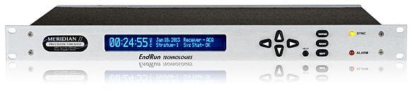
EndRun Technologies has launched two GPS-based timing products.
Meridian II Precision TimeBase.
The Meridian II Precision TimeBase references GPS to provide ultra-accurate time (10 nanoseconds to UTC) and frequency. At the core of Meridian II is a new GPS receiver that EndRun optimized to deliver a variety of traditional- and network-based time and frequency signals.
“The second-generation Meridian II continues EndRun’s heritage of pushing the envelope by delivering an industry-best, UTC time accuracy of 10 nanoseconds.” said Ron Holm, marketing manager, EndRun Technologies. “Meridian II also introduces a security-hardened, high-bandwidth network interface to synchronize evolving, network-centric applications via the Network Time Protocol (NTP) and IEEE-1588 Precision Time Protocol (PTP). Frequency standard customers will be happy to know that the revolutionary ultra-low phase noise and short-term stability performance of the original Meridian continues to be provided.”
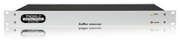
Tycho II Precision TimeBase.
Also new is the Tycho II Precision TimeBase time and frequency standard, which references GPS to provide exceptional time (25 nanoseconds to UTC) and frequency (<1×10-13 per day) accuracy in a security-hardened, network-centric platform.
At the core of Tycho II is a new EndRun GPS receiver that is optimized to take advantage of improved GPS system accuracy. Tycho II delivers a variety of traditional and network-based time and frequency signals and services via a modular, customer-configurable platform. Operational status is easily monitored via the network interface (HTTPS, SNMP, SSH). Intuitive charts are provided to assess current and historical performance of Tycho II, its GPS receiver and reference oscillator.
“The second-generation Tycho II provides our customers with a cost-effective, high-performance time and frequency standard without compromise to security and reliability,” said Dan Paine, sales and support manager, EndRun Technologies. “In addition, Tycho II uses the same network-centric core of our ultra-high performance Meridian II TimeBase. This enables operation as a high-bandwidth, Network Time Protocol (NTP) server and optional IEEE-1588 Precision Time Protocol (PTP) Grandmaster.”
Both the Meridian II and Tycho II have modular architecture that allows customers to configure them to meet specific application requirements.
The units support mission-critical operations in a wide range of government and commercial applications including telecommunications, satellite communications, digital video broadcast, simulcast radio, test range, test and measurement, calibration labs and power utilities.
The U.S. Department of Transportation’s Federal Aviation Administration (FAA) has announced the largest civil penalty the FAA has proposed against a UAS operator for endangering the safety of the national airspace.
The FAA proposes a $1.9 million civil penalty against SkyPan International Inc. of Chicago. Between March 21, 2012, and Dec. 15, 2014, SkyPan conducted 65 unauthorized operations in some of the most congested airspace and heavily populated cities, violating airspace regulations and various operating rules, the FAA alleges. These operations were illegal and not without risk.
The FAA alleges that the company conducted 65 unauthorized commercial UAS flights over various locations in New York City and Chicago for aerial photography. Of those, 43 flew in the highly restricted New York Class B airspace.
“Flying unmanned aircraft in violation of the Federal Aviation Regulations is illegal and can be dangerous,” said FAA Administrator Michael Huerta. “We have the safest airspace in the world, and everyone who uses it must understand and observe our comprehensive set of rules and regulations.”
SkyPan operated the 43 flights in the New York Class B airspace without receiving an air traffic control clearance to access it, the FAA alleges. Additionally, the agency alleges the aircraft was not equipped with a two-way radio, transponder and altitude-reporting equipment.
The FAA further alleges that on all 65 flights, the aircraft lacked an airworthiness certificate and effective registration, and SkyPan did not have a Certificate of Waiver or Authorization for the operations.
SkyPan operated the aircraft in a careless or reckless manner so as to endanger lives or property, the FAA alleges.
SkyPan has 30 days after receiving the FAA’s enforcement letter to respond to the agency.
Wide-Area Wireless Network Synchronization with LocataNets
The United States Naval Observatory conducted several independent frequency synchronization experiments in Washington, D.C., using an alternative PNT technology in multiple network configurations. The results suggest that sub-nanosecond time transfer using this technology may be possible over wide urban areas, and that it could thus serve as a GPS augmentation or back-up solution over wide areas for critical applications that depend on precise time.
By Edward Powers and Arnold Colina
Because of the great responsibility of being the prime source of time for many critical national systems, the United States Naval Observatory’s (USNO’s) clock system must be at least one step ahead of the demands expected to be made on its accuracy. Therefore, innovative methods of transferring precise time and frequency must continually be anticipated, investigated and supported.
The USNO has developed one of the world’s most accurate and precise atomic clock systems, used by many systems requiring highly precise time. The USNO operates the U.S. Master Clock, which provides the precise time source for the GPS satellite constellation run by the Air Force; it is also the time standard for the U.S. Department of Defense. Along with its sister organization, the National Institute of Standards and Technology (NIST), it provides the official time for the entire nation.
To investigate new precise time transfer methods, the USNO desired to independently test Locata’s TimeLoc methodology as a possible technology for maintaining precise frequency synchronization across an urban or wide-area network — the foundation for supporting precise time transfer.
Internet of Everything Ups Timing Requirements
Many critical modern systems such as 4G mobile phone networks, banking, and electricity grids demand high-accuracy time and frequency stability across specified areas. Precise network synchronization is critical for nearly all digital networks, and more stringent network stability requirements are expected to emerge as the user base for these applications continues to grow. To date, the preferred method to achieve this performance is via synchronization from GPS. However, the vulnerability of GPS signals causes growing concern among industry experts. Many actively seek alternative means of precise time transfer and frequency stability across wide areas.
Alternative position, navigation, and timing (PNT) technologies such as chip scale atomic clocks (CSAC), precision time protocol (PTP), and enhanced long range radio navigation (eLoran) are proposed or operational today, with each serving different markets.
Meanwhile, timing needs for wireless protocols continue to increase with the proliferation of mobile phones and other wireless communication devices. To accommodate a booming user base, wireless spectrum must be carefully managed to improve bandwidth and channel efficiency. Wireless communication performance is fundamentally dependent upon precise time and frequency, so improvements in highly accurate timekeeping methods will permit better spectrum utilization, which in turn permits more users and more bandwidth per user.
Clearly, synchronization is a core enabling technology for modern digital systems, both for radiopositioning and the world’s telecommunications highways. But synchronization is taken for granted because, when it works well, it is effectively invisible. Without it, however, everything is likely to fall apart.
Synchronization will become even more crucial for the next generation of digital systems. A recent paper by the U.S. National Institute of Standards and Technology (NIST) states that we stand at the advent of a revolutionary new economy fueled by a global Internet of Everything (IoE), in which 37 billion new things will be connected to the Internet by 2020.
This NIST paper adds that “One fundamental enabler of this revolution will be the marriage of timing signals and data that breaks through the existing barriers. Timing is critical for future development and improvements.”
Improved wireless synchronization has proved very challenging to realize, as the timer in each network node is derived from an independent oscillator that is affected by long/short term frequency drifts and jitter. Many alternative timekeeping methods present serious limitations in terms of precision or network size.
Encouraged by earlier published results showing that Locata Corporation’s radio-based PNT technology enables network synchronization at the nanosecond level, and suggesting that it could perform comparably across large urban areas, the United States Naval Observatory (USNO) conducted its own synchronization experiments on Locata technology.
Real-World Challenges
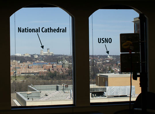
The USNO campus is situated about 4 kilometers northwest of the White House in Washington, D.C. The grassy tree-lined campus is, unfortunately, a relatively small area for testing wide-area synchronization capabilities. It became apparent that realistic long-distance tests would necessitate extending the LocataNet outside USNO boundaries. This meant coordinating access to other facilities in theWashington, D.C., area to allow remote housing of LocataLites and their antennas. As many researchers will confirm: when real-world testing requires access to multiple external sites and their disparate administrations, the coordination required to keep everything on track can quickly become the most daunting challenge of the exercise. We needed to find cooperative facilities, preferably with line-of-sight (LOS) to the USNO and its Master Clock in order to establish the best TimeLoc link between facilities. As we also wanted to exercise TimeLoc’s ability to cascade its synchronization through multiple LocataLites, ever more D.C. facilities would need to be involved. Predictably, it transpired that not many facility managers in the Washington district were eager to help the USNO broadcast and receive new and unknown signals in or around their government buildings! And those who were amenable to support the demonstration either lacked a LOS, or were not willing to assist without considerable monetary compensation.
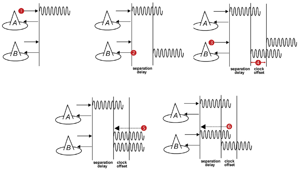
Step 1: LocataLite A transmits a unique signal (code and carrier). Step 2: LocataLite B acquires, tracks and measures the signal generated by A. Step 3: LocataLite B generates its own unique signal (code and carrier) which is transmitted in the normal manner. Importantly, the transmitted signal is received by the receiver section of LocataLite B as well. Step 4: LocataLite B calculates the difference between the signal received from LocataLite A and its own locally generated and received unique signal. Ignoring propagation errors, the differences between the two signals are due to the difference in the clocks between the two devices, and the geometric separation between them. Step 5: LocataLite B adjusts its local oscillator to bring the differences between its own signal and LocataLite A’s received signal to zero. The signal differences are continually monitored and adjusted so that they remain zero. In other words, the local oscillator of B follows precisely that of A. Step 6: The system corrects for the geometrical offset (range) between LocataLite A and B, using the known coordinates of the LocataLites’ antennas. When this step is accomplished, TimeLoc has been achieved.
After months of attempts to secure appropriate partners for this demonstration, we finally found some supporters in the shape of the Federal Aviation Administration Building in Rosslyn, Va., and the National Cathedral in Washington, D.C. Regrettably, it turned out that these facilities were not going to be available at the same time! Logistic challenges never end. This scheduling reality necessitated spreading the TimeLoc demonstration over several months in three different blocks of trials. Nevertheless, we were eventually able to devise a plan which leveraged access to the USNO and still accommodated the timetables of the supporting external facilities.
A series of experiments were planned to measure and evaluate the stability between master and slave LocataLite 1-pulse per second (PPS) signals in several urban LocataNet configurations. Many of the trials were specifically designed to measure TimeLoc’s ability to cascade multiple times through multiple LocataLites, exercising the technology’s capabilities over increasing distances and hence correspondingly larger notional coverage areas.
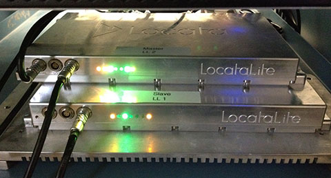
Figure 2. LocataLites under test at USNO.
Locata signals were broadcast in the Industrial, Scientific and Medical (ISM) 2.4 GHz radio band, commonly known as the Wi-Fi band, with a total radiated power of 200–500 mW. LocataLites and their respective antennas were installed at locations that permitted LOS between units, according to whichever specific LocataNet configuration was being evaluated at the time. In each configuration, the master LocataLite, designated as LocataLite 1, was synchronized to the USNO Master Clock so that the Master Clock’s time would be propagated through the LocataNet. Both the master and slave LocataLite 1PPS signals were collected into a time interval counter and the time difference between their rising edges was measured.
When tracking radio frequency signals over a significant distance, tropospheric delay becomes an important error source for measurements used in timing solutions. The speed of light can only be assumed to be universally constant in a vacuum, so atmospheric temperature, pressure and humidity materially changes the speed of light when propagating through air. In fact, using standard atmospheric parameters, the unmodeled tropospheric delay is surprisingly large — approximately 280 parts per million (ppm), which equates to slowing down almost one nanosecond over each kilometer of radio transmission. Obviously, as transmission distances increase, tropospheric error becomes a substantial factor which must be accounted for in hyper-accurate timing systems. Devising methodologies that effectively mitigate large tropospheric errors becomes essential.
To help solve this problem, Locata developed new tropospheric models that use relatively inexpensive meteorological (MET) stations which measure temperature, pressure and relative humidity at the LocataLite sites. This modeling alone is able to mitigate the tropospheric effects to within just few parts per million. This proved to be an essential feature, as the weather during the course of the entire months-long testing campaign varied significantly among the separate trials.
The TimeLoc Process
LocataNets function as local ground-based replicas of the satellite-based GPS position and timing networks. A LocataNet can be designed and configured by the user to deliver a powerful, local, controllable, tailored signal as required by different applications.
The easiest LocataNet layout to describe is a hub-and-spoke model consisting of a single master LocataLite transceiver and one or more slave LocataLites. More complex network configurations have been deployed in many commercial systems in use today. The patented process by which slaves are synchronized to the master (or other slaves) is known as TimeLoc.
In 2013, a University of New South Wales team demonstrated that Locata’s radio-based TimeLoc technology provided accurate time transfer (~5 ns) and frequency stability (~1 ppb) across a large distance of 73 kilometers (45.4 miles). This significantly outperforms GPS for wireless time transfer. Given this demonstrated radius of transmission in a rudimentary configuration, Locata was shown as being able to supply nanosecond-accurate time to a 146 km diameter circle, which would cover 16,750 km2 — almost 200 times the size of Manhattan. Ranges greater than this can be deployed if required for safety-of-life, military or government-mandated systems.
As TimeLoc is accomplished without the use of atomic clocks, this represents a new level in precision network synchronization of this scale. It could conceivably serve as a GPS augmentation or back-up solution over wide areas for critical applications that depend on precise time.
Since Locata technology was originally developed as a high-accuracy non-GPS-based positioning and navigation solution, the time synchronization accuracy requirements for a LocataLite transceiver are very high. If sub-centimeter positioning precision is desired for a Locata receiver, every smallest fraction of a second is significant; for example, a 1-nanosecond error in time equates to an error of approximately 30 centimeters.
TimeLoc wireless synchronization enables LocataLites to achieve high levels of synchronization without atomic clocks, without external control cables, without differential corrections, and without a master reference receiver.
In theory, there is no limit to the number of LocataLites that can be synchronized together. TimeLoc allows a LocataNet to propagate into difficult environments or over wide areas. For example, if a third LocataLite C can only receive the signals from B (and not A) then it can use these signals from B for time synchronization instead. The only requirement for establishing a LocataNet using TimeLoc is that LocataLites must receive signals from one other LocataLite. This does not have to be the same central or master LocataLite, since this may not be possible in difficult environments with obstructions, or when propagating the LocataNet over wide areas.
This method of cascading TimeLoc through intermediate LocataLites has been proven in a growing number of real-world operational LocataNets, including a network in use today by the U.S. Air Force which is configured to cover up to 2,500 square miles (6,500 square kilometers) of the White Sands Missile Range in New Mexico.
In large networks where extremely high synchronization accuracies are required, it is useful to incorporate a meteorological sensor at each LocataLite to monitor the change in weather over considerable distances. This is certainly the case for long-range systems such as the USAF LocataNet installed at the huge White Sands Missile Range, where distances of over 50 km can be found between LocataLites. However, for the purposes of these USNO Washington experiments, where the longest point-to-point transmission distance was 2.9 km, it was assumed that weather parameters would be virtually identical at all LocataLite locations. Therefore only one MET station was employed within the entire network, which for these trials was collocated with the master LocataLite.
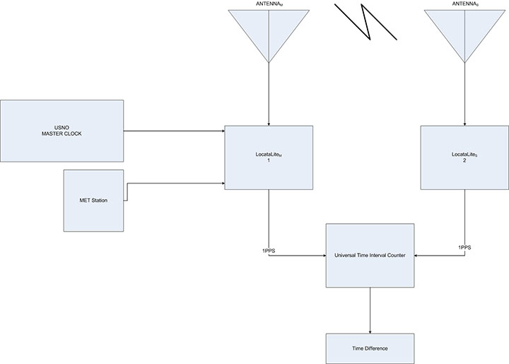
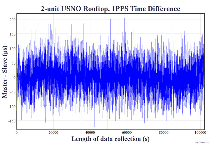
The very first experiment conducted by the USNO to gain some familiarization with TimeLoc was run entirely within the grounds of the USNO campus. It employed two LocataLites with their respective antennas on the roof of USNO Building 78. In this initial configuration the antennas were positioned 15.24 m apart. It was intended to use the measured result as a baseline against which TimeLoc synchronization over longer distance could be compared. This first arrangement is referred to as the two-node setup. A diagram of this configuration is shown in Figure 3.
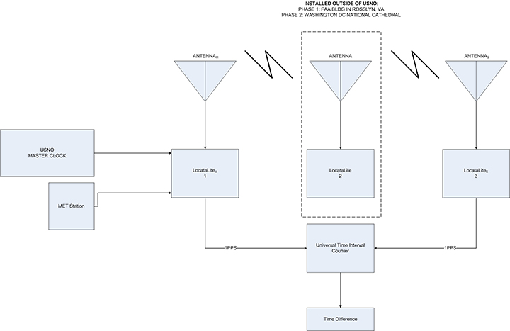
Second and third experiments demonstrated Locata’s ability to cascade the master 1PPS signal to an intermediary slave LocataLite, which in turn transmits a signal to which a third LocataLite can TimeLoc. This LocataNet configuration is referred to as the three-node setup (Figure 4).
Figure 4. Three-node setup (total range: 5.794 km/3.6 mi and 2.401 km/1.49 mi).
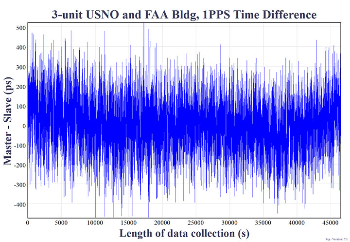
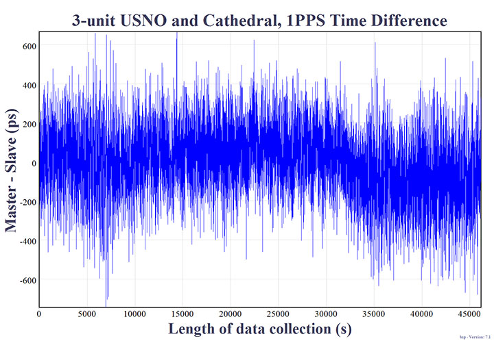
This experiment was conducted twice using two different intermediate LocataLite locations. The first intermediate location was indoors on the top floor of the FAA Building in Rosslyn, Va. (Figure 5). The distance between the master/slave antennas to the intermediate antenna in the FAA building was 2.897 km, but since the signal was propagated through a tinted window, the received signal strength inside the building was greatly attenuated, effectively simulating a much longer transmission distance. The second intermediate (LocataLite 2) location was from the balcony of the National Cathedral’s Ringing Chamber. In this case the distance between USNO LocataLite 1 master/slave to the intermediate antenna in the National Cathedral was approximately 1.183 km.
Figure 5. Intermediate LocataLite 2 antennas inside FAA building. In the distance, both the USNO and the National Cathedral are visible.
In both cases in Figure 4, the distance between master and terminal slave antennas was 3.048 m on the USNO building, but they were intentionally not TimeLoc’d to each other. The timing signal was therefore forced to route through the intermediate LocataLite 2 at either the FAA Building or the National Cathedral.
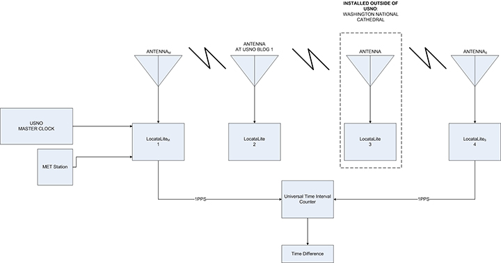
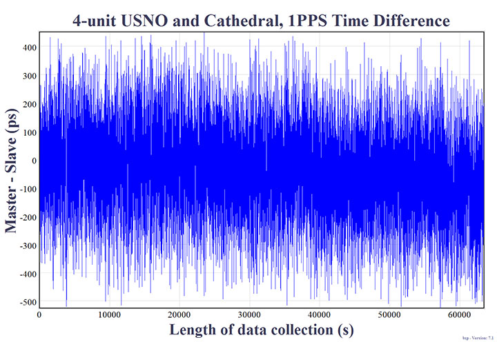
A fourth experiment included yet another intermediate cascade where the TimeLoc signal was transmitted from the second to a third LocataLite/antenna before arriving at the fourth LocataLite in the chain. This LocataNet configuration is referred to as the four-node setup. A diagram of the setup is shown in Figure 6, and it now added a LocataLite on USNO Building 1 to expand the set-up, along with the intermediate LocataLite installed at the National Cathedral (Figure 7).
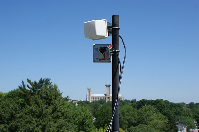
Figure 6. Four-node setup (total range: 2.413 km/1.5 mi).Figure 7. LocataLite antennas outside the Ringing Chamber of the National Cathedral Spire.
Referring to Figure 6, the distance between the master LocataLite (antenna 1) at USNO Building 78 and the LocataLite (antenna 2) at USNO Building 1 was approximately 42.672 m. The distance between the USNO Building 1 (antenna 2) to the Washington National Cathedral (antenna 3), was approximately 1.144 km. The distance between the Washington National Cathedral (antenna 3) back to antenna 4 on USNO Building 78 was approximately 1.183 km. The total range in this four-node chain was 2.413 km. In this configuration, LocataLites 1 and 4 are intentionally not TimeLoc’d to each other, forcing the 1PPS signal to be routed through LocataLites 2 and 3.
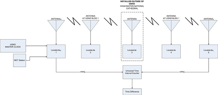
A fifth experiment included yet one more LocataLite and antenna at USNO Building 1 (Figure 9), totaling cascaded TimeLoc among five LocataLites and their respective antennas: the five-node setup, shown in Figure 8. In this configuration LocataLites 1 and 5 are intentionally not TimeLoc’d to each other, forcing the 1PPS signal to be routed through LocataLites 2, 3 and 4.
Figure 8. Five-node setup (total range: 2.427 km/1.51 mi).Figure 9. LocataLite antennas on USNO Building 1. National Cathedral in background.
Measurement Methodology
A measurement of time difference between master and slave LocataLite 1PPS readings was done using a Stanford SR620 universal time interval counter. The rising edge of the 1PPS signals were inspected at 1-Volt trigger level. A 10 MHz reference was provided to the counter from the USNO’s Master Clock. Channels A and B on the counter were designated to the master and slave 1PPS signals respectively. Data were collected from the counter through serial connection to a PC. The length of each experiment was time-limited in some way because of limited access to facilities, such as the FAA building or National Cathedral. However, a minimum of at least 30,000 seconds (8.33 hours) of data were collected for each test to characterize the overall stability of the 1PPS signals between master and terminal slave LocataLites.
Collected Data
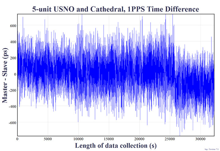
Figures 10 to 14 show the normalized 1PPS time difference between the master LocataLite and the terminal slave LocataLite. Normalization effectively removes errors due to unsurveyed antenna locations and uncorrected cable delays; hence it highlights the frequency coherence of the network.
Figure 10. Two-node setup on USNO rooftop, collected for slightly more than 1 day. Distance: 15.24 m/50 ft. Synchronization Standard Deviation (SSD) = 51.095 picoseconds.Figure 11. Three-node setup at USNO and FAA Building, collected for over 12 hours: 5.794 km/3.6 mi. SSD = 127.333 picoseconds.Figure 12. Three-node setup at USNO National Cathedral, collected for over 12-hours: 2.401 km/1.49 mi. SSD = 171.325 picoseconds.Figure 13. Four-node setup at USNO with cascades at National Cathedral and USNO building 1, collected for over 17-hours: 2.413 km/1.5 mi. SSD = 145.247 picoseconds.Figure 14. Five-node setup with cascades at National Cathedral and 2 hops at USNO building 1, collected for over 8-hours: 2.427 km/1.51 mi. SSD = 197.766 picoseconds.
Results
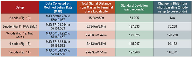
The results in Table 1 show the 1PPS signal variability for each LocataNet under evaluation. These values represent the frequency coherence between master and terminal slave LocataLite 1PPS signals for each experiment.
Table 1. LocataNet frequency stability.
The two-node setup used two LocataLite antennas located within 15.24m of each other. The measured precision standard deviation was 51.095 picoseconds. This value is a culmination of the total Locata noise budget, which is expected to consist of TimeLoc noise, residual tropospheric error, multipath change (signal scattering/diffusion), PPS generation, and PPS measurement. This two-node result can be used as a baseline for Table 1 measurement results over longer distances. The differences are shown in the last column of Table 1. For example, cascading TimeLoc over the 5.794 km three-node setup introduced an additional deviation of 76.238 picoseconds, compared to the two-node set-up.
The three-node setup tested the effect of adding a TimeLoc cascade wherein the Locata signal from the master is routed to an intermediate LocataLite, and then to the terminal slave. When the master LocataLite signal was cascaded through the intermediate LocataLite at the FAA Building, the configuration showed a standard deviation of 127.333 ps across a total signal path length of 5.794 km. Alternatively, when the master LocataLite signal was cascaded through the intermediate LocataLite at the National Cathedral, that three-node configuration showed a standard deviation of 171.325 ps across a total signal path length of 2.401 km.
Interestingly, it appears that in the two different three-node setups, the intermediate cascade to the FAA building (2.9 km from the master and terminal slave LocataLites) delivered slightly better time transfer performance than the configuration which leveraged the closer (1.183 km) National Cathedral intermediate cascade. We believe this is attributable to the fact that the line-of-sight between USNO Building 78 (the site of the master and terminal slave) and the National Cathedral (the intermediate cascade) was completely obscured by heavy foliage seen in Figure 9, and that this particular configuration required the signal to pass through the foliage twice when being transmitted back and forth. Not only does foliage introduce multipath, but the properties of this foliage also changed regularly according to wind and moisture — two weather attributes that varied significantly over the course of the week in which those particular experiments were set up and run. This theory seems reasonable, since the four-node setup only required the signal to pass through this foliage once, and the recorded performance was better than the three-node setup — despite the fact that an additional TimeLoc cascade point was introduced.
The four-node setup included TimeLoc cascades at USNO Building 1 and the Washington National Cathedral. In this configuration, the data from Table 1 shows a standard deviation of 145.247ps across a total signal path length of 2.413 km.
The five-node setup included yet another TimeLoc cascade between the National Cathedral and Building 1 at USNO before reaching the terminal LocataLite slave. In this configuration, the data from Table 1 shows a standard deviation of 197.766ps across a total signal path length of 2.427 km.
Frequency Stability
Frequency stability is best measured over long periods. Because all of the equipment in the two-node setup was located on USNO premises, it could be run undisturbed for a longer period of time than configurations which required access to external facilities outside of the USNO’s control. Data obtained from the two-node setup were used to calculate the frequency stability between the two TimeLoc’d LocataLites. The length of this data set was 28 hours, 22 minutes, and 40 seconds. During this period, the approximate one-day frequency stability was measured as 1×10-15 (1 part per quadrillion).
To put this measurement into a more practical context: Stratum 1 is defined as a source of frequency with an accuracy of at least 1×10- 11, hence Stratum 1 performance generally originates from an atomic standard. For example, Cesium beam atomic clocks typically provide better performance than this, with one day Allen deviation stabilities in the mid- Ex10-14 (usually stable to between 3×10-14 to 6×10-14). Rubidium clocks are typically never more stable than 1×10-13 and Maser clocks are typically stable to mid-to-low Ex10-15 over one day.
Locata’s link stability — achieved without the use of atomic clocks — is clearly capable of distributing Stratum 1 frequency and precise time without substantially degrading the reference clock stability. This measured performance is significant, because a stable network is an essential prerequisite for precise time and frequency transfer. Moreover, for many traditional timing applications and developing digital and IoE applications, stability is more important than accuracy; just as for most advanced technology applications, frequency is more important than time of day.
Conclusions
The five USNO experiments suggest that the variations of the measured frequency synchronization between master and terminal slave LocataLites were not inevitably attributable to the distance between LocataLites, but rather governed by the number of nodes or cascade points in the LocataNet configuration, and LocataLite signal quality. Each signal cascade through an intermediate LocataLite introduced ~25ps of jitter into the solution.
Additionally, it was noted that transmitting TimeLoc signals across an urban environment did not always allow for unobstructed line-of-sight or completely open-sky environments. For instance, some of the LocataNet configurations required the signal to travel through dense, leafy trees which appeared to slightly affect overall frequency stability. Additionally, one FAA configuration required the signal to travel indoors through a tinted window which ultimately affected received signal strength.
These USNO tests highlighted the capability of the LocataLite as a viable option for a stable 1PPS distribution setup within an urban environment in support of applications like cell tower synchronization in “GPS-challenged” environments. All tested configurations demonstrated frequency synchronization of less than 200 picoseconds. This is significantly better than any other known wireless network synchronization methodology, including GPS. Furthermore, if clear line-of-sight is available between a master and slave LocataLite, the 2-node precision has been shown to be on the order of 50ps, and has one-day stabilities to 1×10-15.
These results, reinforced by those previously reported in University of New South Wales tests over a very large area, suggest that distance between nodes is not a significant factor, provided that sufficient signal quality is maintained. Thus, there are no theoretical or technical problems with scaling LocataNets to very large areas. In fact, this has already been demonstrated at the White Sands Missile Range where the USAF has now deployed a fully-operational Locata network that covers up to 2,500 square miles (6,500 square km), about 80 times the size of Manhattan.
The USNO trials reported here have clearly demonstrated TimeLoc’s relative picosecond-level synchronization of independent Locata networks. If this highly-stable network capability were not in place, precise time transfer would not be possible. The next step is to demonstrate how well a LocataNet can deliver absolute time transfer of the USNO’s Master Clock time to any other network node across similar areas of Washington, D.C.
Acknowledgments
The authors would like to thank James Shepherd of the National Cathedral and Paul Worcester of the FAA for use of their respective buildings. The authors would also like to thank Locata personnel for the use of their equipment and technical assistance in setting up the LocataNets under evaluation.
This article is based on a paper presented at ION GNSS+ 2015.
Disclaimer
Though particular vendor products are mentioned, neither official USNO endorsement nor recommendation of any product is herein implied.
Edward Powers is the GNSS and Network Time Transfer Operations Division Chief at USNO. He also serves as an advisor to the USAF GPS Directorate supporting space atomic clock development, modernized GPS III navigation message design, GPS accuracy improvement studies, and GPS UE development.
Arnold Colina is an electronics engineer in USNO’s GNSS and Network Time Transfer division, tasked with providing accurate UTC reference through GPS and performing calibration tests on GNSS receivers.
Timing Versus Synchronization
“They say “timing is everything” but nowadays it’s probably more correct to say “synchronization is everything”. There is a significant difference, yet many are surprised to learn they are not the same thing.
“Time dependent” applications rely on their clocks being close to the “real time”, as defined by a consensus of super-accurate atomic clocks managed by national bodies like the USNO. Once agreed upon by the labs, this “real time” can be distributed to various “time dependent” networks as a reference time to drive their operations.
“Time synchronized” applications, on the other hand, employ a methodology in which a common network time can be transferred to each network node. In other words, often the real technology enabler is that all the clocks in a defined network are synchronized to each other, even if they all run to what is any arbitrarily defined time-base. The “real time” doesn’t matter as much as how closely the node times agree with each other. As Einstein famously taught us: “Everything is relative.”
For example, accurate synchronization enables GPS positioning to work because a user’s GPS receiver relies on time-of-arrival comparisons from four or more satellites transmitting their signals at the same instant. But — even in this GPS paradigm where atomic clocks are always touted to be the most fundamental of requirements — it is important to appreciate this: A GPS user’s receiver does not care how, or to what “time,” the satellites are made synchronous. The only things the user receiver needs to know is where the satellites are, and that the satellites are synchronized when they transmit their signal.
Unfortunately sustaining high-precision, reliable time synchronization of multiple network nodes is a mammoth engineering task. Just ask the US Air Force! All clocks, no matter how accurate they are, eventually drift, so they cannot remain synchronized without comparison and adjustment.
Given the world’s exploding, insatiable demand for more data transmitted via ever-faster wireless systems, synchronization will become even more important than it is today. More wireless users and more bandwidth per user means that nanosecond — or even picosecond — network synchronization is one of the emerging engineering challenges of the 21st century. There are few resource on earth which are as scarce, or more precious today, than spectrum. So there is no question that better or cheaper ways to greatly improve network frequency and synchronization will translate directly into better use of the world’s exceptionally valuable, extremely limited spectrum resource.