The Federal Aviation Administration has established an interim policy to speed up airspace authorizations for certain commercial unmanned aircraft operators who obtain Section 333 exemptions. The new policy helps bridge the gap between the past process, which evaluated every UAS operation individually, and future operations after the FAA publishes a final version of the proposed small UAS rule.
Under the new policy, the FAA will grant a Certificate of Waiver or Authorization (COA) for flights at or below 200 feet to any UAS operator with a Section 333 exemption for aircraft that weigh less than 55 pounds, operate during daytime Visual Flight Rules (VFR) conditions, operate within visual line of sight (VLOS) of the pilots, and stay certain distances away from airports or heliports:
5 nautical miles (NM) from an airport having an operational control tower; or
3 NM from an airport with a published instrument flight procedure, but not an operational tower; or
2 NM from an airport without a published instrument flight procedure or an operational tower; or
2 NM from a heliport with a published instrument flight procedure
The blanket 200-foot COA allows flights anywhere in the country except restricted airspace and other areas, such as major cities, where the FAA prohibits UAS operations. Previously, an operator had to apply for and receive a COA for a particular block of airspace, a process that can take 60 days. The agency expects the new policy will allow companies and individuals who want to use UAS within these limitations to start flying much more quickly than before.
Section 333 exemption holders will automatically receive a blanket 200-foot COA. For new exemption holders, the FAA will issue a COA at the time the exemption is approved. Anyone who wants to fly outside the blanket parameters must obtain a separate COA specific to the airspace required for that operation.
More information on the UAS exemption process is available on the FAA’s UAS page.
Port Vila, the capital of Vanuatu, viewed by Pléiades satellites, before Cyclone Pam.Port Vila, the capital of Vanuatu, viewed by Pléiades satellites after the passage of Cyclone Pam.
Following Cyclone Pam, Airbus Defence and Space has acquired Pléiades and SPOT 6 and 7 imagery over the island nation of Vanuatu to support the International Charter and Copernicus Emergency Management Service.
The data acquired will assist in assessing the damage and help rescue organizations in the delivery of humanitarian aid.
The before and after Pléiades images over Port Vila, that can be downloaded here, show the devastation caused by the cyclone. The “before” Pléiades image was acquired on April 9, 2014, and the “after” Pléiades image was acquired on March 16, three days after the Cyclone hit Port Vila.
MAPPS, an association of private-sector geospatial firms, has elected George Southard of Trimble Navigation Limited to the MAPPS Board of Directors, representing the association’s associate members.
At its winter conference in January, the MAPPS membership approved a change to the association’s bylaws to create a non-voting, ex officio seat on the board, to be elected by and from associate member firms. Southard is the first to hold the seat, having been elected by his fellow associate members earlier this month.
MAPPS is the a national association of firms in the surveying, spatial data and geographic information systems field in the United States. MAPPS member firms are engaged in surveying, photogrammetry, satellite and airborne remote sensing, aerial photography, hydrography, aerial and satellite image processing, GPS and GIS data collection and conversion services. Associate members include firms that provide products and services to member firms, as well as other firms worldwide.
Southard has been an active participant in MAPPS since 1993. He’s served on various committees and presented at MAPPS conferences. He has served on the MAPPS Membership, Aerial Acquisition, Program and Associate Members Committees. He has been chair of the Associate Members Committee and most recently as the chair of the UAS Sub-committee to the Aerial Acquisition Forum. Southard has been on the association’s Nominations Committee for several MAPPS Board elections and was the MAPPS representative to the ASPRS Frank Moffitt Memorial Scholarship Committee.
“We’re pleased to have George join the board,” said MAPPS President Jeff Lower (Precision Aerial Reconnaissance, LLC). “He is a recognized leader in our profession and will bring a valued and respected voice to MAPPS and our board.”
The Russian company Credo-Dialogue has released Credo GNSS 1.0, a GNSS processing software.
Credo GNSS 1.0 is designed for processing of satellite geodetic measurements in differential mode. In this mode, the simultaneous operation of two or more receivers forms the baseline.
The input can use the following types of data:
satellite geodetic measurements and ephemeris format RINEX (2.0-3.2);
satellite geodetic measurements and ephemeris formats satellite geodetic receivers (in accordance with the import module);
import point coordinates from text files in any format, user-configurable;
precise ephemeris (can be downloaded automatically to the time span of the project); and
Also in the program, users can view images from web services such as Google Maps, Bing and Express Kosmosnimki.
Credo GNSS supports a variety of coordinate systems, including Transverse Mercator, Mercator, PseudoMercator, Lambert Conformal Conic and Orthographic.
To learn more about the software, click here or view the video below.
Feedback Business Consulting has released a report on opportunity in the Indian GPS current market scenario, structure and practices.
The market scenario in “Opportunity in the Indian Global Positioning System (GPS) Market — 2015” includes current market size estimates by players, top companies, product categories, end user segments and regions. The product categories include tracking and navigation; segments include automobile, logistics, IT, ITe and mobile phones.
The market structure section details the value of key players’ presence across products and end user segments. The market practices section explores understanding the GPS market sets in business, market trends, distribution practices and pricing.
Some of the key companies featured in the report include Aadhithya Systems, Blaupunkt India, Caska India, Garmin India, Google Maps India and Locationguru.
The report also provides a snapshot of key competition and past market trends with a forecast over the next five years. Anticipated growth rates and the factors driving and impacting growth are also provided.
Market data and analytics have been derived from a combination of primary and secondary sources.
The public has until April 24 to comment on a framework of regulations proposed by the Federal Aviation Administration (FAA) in February. The regulations would allow routine use of certain small unmanned aircraft systems (UAS) in today’s aviation system, while maintaining flexibility to accommodate future technological innovations, the agency said.
The FAA proposal offers safety rules for small UAS (under 55 pounds) conducting non-recreational operations. The rule would limit flights to daylight and visual-line-of-sight operations. It also addresses height restrictions, operator certification, optional use of a visual observer, aircraft registration and marking, and operational limits.
The new rules would not apply to model aircraft. However, model aircraft operators must continue to satisfy all of the criteria specified in Sec. 336 of Public Law 112-95, including the stipulation that they be operated only for hobby or recreational purposes.
The public will be able to comment on the Small UAS Notice of Proposed Rulemaking for 60 days from the date of publication in the Federal Register. The proposed regulation was published for public comment on February 23, and comments will be accepted through April 24.
A new version of the online GAPS precise point positioning software is now available. GAPS — GPS Analysis and Positioning Software — is offered by the University of New Brunswick Geodesy and Geomatics Engineering Department.
The latest release provides capabilities for handling GPS data files in both RINEX 2 and 3 formats, whether Hatanaka-compressed or not, along with a number of receiver raw file formats. Also, additional input and output data-quality verification is now performed.
More information on the release can be found here, and the new version is available here.
Spirent Communications has added capabilities to its ultra-wideband GSS6425, which enable recording up to 150MHz bandwidth of GNSS signals. Users can now record up to three RF frequency bands at any one time with 10-, 30- or 50-MHz bandwidth each. Other enhancements include the ability to record up to four video streams, USB 3.0 support and easy remote-control using tablet or smartphone.
A single portable test system, the ultra-wideband GSS6425 allows customers to record GPS L1 and L2 and GLONASS L1 and L2 signals commonly needed for applications requiring very high accuracy such as surveying, precision agriculture, automotive research, and advanced navigation.
“Customers undertaking field testing are increasingly looking for portable and easy to use test solutions,” said Rahul Gupta, commercial segment lead for Spirent’s positioning division. “With these new abilities they can now easily configure, monitor, and control the GSS6425 using their mobile phone or tablet over Wi-Fi.”
Recording of four video streams by attaching webcams allows the user to capture visual records of any location. This enables users to fully understand the conditions at the time of recording, not only inside the vehicle (including activity on the dashboard, facial expressions, navigation unit, and more) but also outside the vehicle (such as top, front and back scenes, capturing building types, and movement in and out of a tunnel), which is useful especially during the post-processing phase.
The support for USB 3.0 has also been added, to facilitate faster recording transfer to and from the test system. Users can also use this to record data straight onto to any external hard drive supporting this interface, to record for a longer duration of time.
Spirent’s pecord and playback GSS6425 test solution provides a popular variety of applications, including:
Automotive R&D testing: With the connected car becoming a reality, record and playback testing techniques are proving to be very useful, saving engineering teams time and cost spent on drive testing. With the GSS6425, customers can not only record GNSS signals but also up to four video streams, CAN bus data and sensor data synchronously.
Authorized user tests: The GSS6425 can record GPS signals simultaneously for several hours at L1 and L2 frequencies — sufficient to capture both the GPS M-codes and Y-codes.
By Thorsten Lück, Günter Heinrichs, IFEN GmbH, and Achim Hornbostel, German Aerospace Center
This article discusses the GALANT adaptively steered antenna array and receiver and demonstrates the test scenarios generated with the GNSS simulator. Exemplary results of different static and dynamic test scenarios are presented, demonstrating the attitude determination capabilities as well as the interference detection and mitigation capabilities.
The vulnerability of GNSS to radio frequency interference and spoofing has become more and more of a concern for navigation applications requiring a high level of accuracy and reliability, for example, safety of life applications in aviation, railway, and maritime environments.In addition to pure power jamming with continuous wave (CW), noise or chirp signals, cases of intentional or unintentional spoofing with wrong GNSS signals have also been reported.
Hardware simulations with GNSS constellation signal generators enable the investigation of the impact of radio interference and spoofing on GNSS receivers in a systematic, parameterized and repeatable way. The behavior of different receivers and receiver algorithms for detection and mitigation can be analyzed in dependence on interference power, distance of spoofers, and other parameters. This article gives examples of realistic and advanced simulation scenarios, set up for simulation of several user antennas simultaneously.
The professional-grade high-end satellite navigation testing and R&D device used here is powerful, easy to use, and fully capable of multi-constellation / multi-frequency GNSS simulations for safety-of-life, spatial and professional applications. It provides all L-band frequencies for GPS, GLONASS, Galileo, BeiDou, QZSS, SBAS and beyond in one box simultaneously. It avoids the extra complexity and cost of using additional signal generators or intricate architectures involving several hardware boxes, and offers full control of scenario generation. A multi-RF capable version provides up to four independent RF outputs and a master RF output that combines the RF signal of each of the up to four individual RF outputs.
Each individual RF output is connected to one or more “Merlin” modules (the core signal generator module for one single carrier) allowing simulation of up to 12 satellites per module. Because of the flexible design of the Merlin module, each one can be configured to any of the supported L-band frequencies.
As one chassis supports up to nine individual Merlin modules, different Multi-RF combinations are feasible:
two RF outputs with up to four modules each
three RF outputs with up to three modules each
four RF outputs with up to two modules each.
With these configurations, the user can simulate different static or dynamic receivers or even one receiver with multiple antennas, covering such challenging scenarios as ground networks, formation flying or use of beam-forming antennas.
As the user is free to assign each individual module to a dedicated simulated antenna, the user could also employ up to nine modules to simulate nine different carrier signals for one single antenna using the master RF output, thus simulating the complete frequency spectrum for all current available GNSS systems in one single simulation.
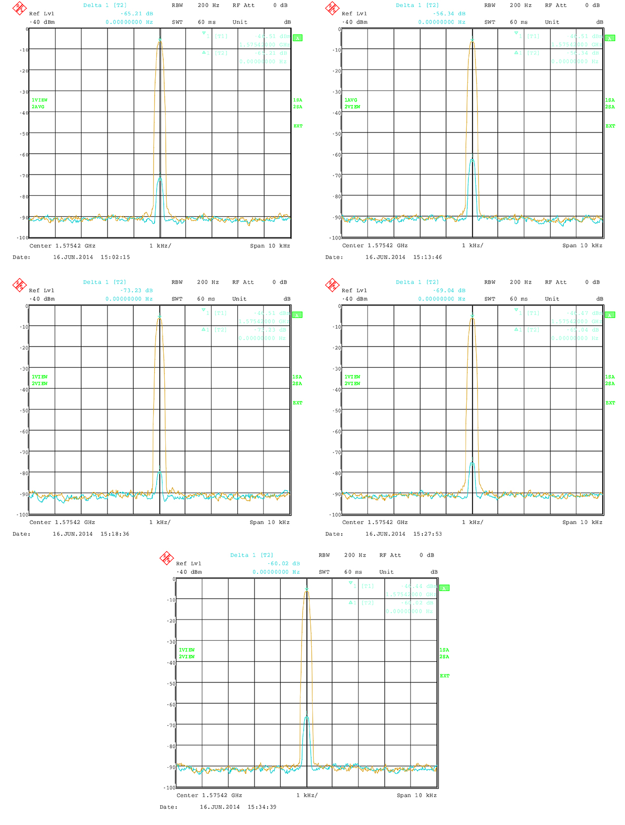
All modules are calibrated to garantee a carrier phase coherency of better than ±0.5°. Figure 1 shows the output at the RF master of two modules assigned to the same carrier but with a phase offset of 180°.
Figure 1. Carrier-phase alignment of the high-end simulator with six modules compared to the first module.
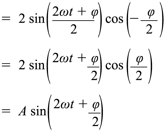
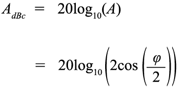
Theoretically, the resulting signal should be zero because of the destructive interference. In practice, a small residual signal remains because of component tolerance, small amplitude differences and other influences. Nevertheless the best cancellation can be seen at this point. The phase accuracy can now simply be estimated from the measured power level of the residual signal:
(1)
(2)
with
This means that the sum of two sine waves with the same frequency gives another sine wave. It has again the same frequency, but a phase offset and its amplitude is changed by the factor A. The factor A does affect the power level. If φ is 180° then A is 0, which means complete cancellation.
So A shows the power of the resulting signal relative to the single sine wave. It can also be transformed to dB:
(3)
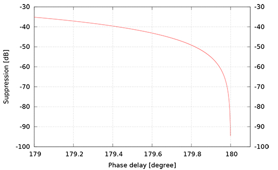
Figure 2 shows the carrier suppression as a function of carrier phase offset with a pole at 180ϒ.
Figure 2. Carrier suppresion as a function of phase delay.
The factory calibration aligns the modules to a maximum of 0.5ϒ misalignment. The measured suppresion therefore shall be better than 41.18 dBc. In practice, the residual signal is also caused by other influences, so that the actual phase alignment can be expected to be much better.
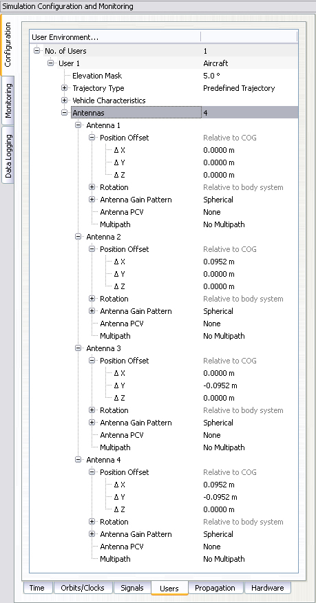
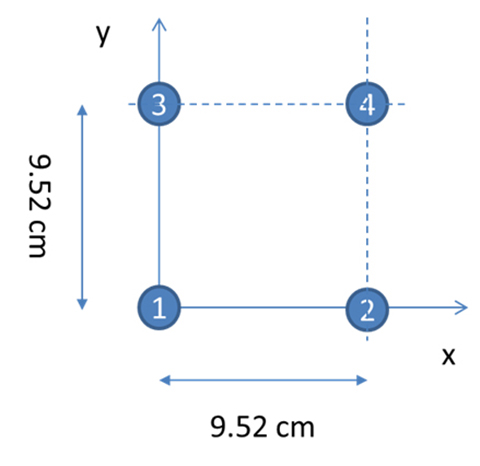
With four RF outputs, the received signal of a four element antenna can be configured very easily. Figure 3 shows the dialog to configure a four-element antenna with the geometry shown in Figure 4. Note that the antenna elements are configured in the body-fixed system with the x-axis to front and the y-axis to the right (inline with a north-east-down, NED, system when facing to north), while the geometry shown in Figure 4 follows an east-north-up (ENU) convention.
Figure 3. Configuration of individual antennas per receiver.Figure 4. Geometry of the GALANT four-element phased-array antenna (view from top).
The following sections give an overview of multi-antenna systems and discuss results from a measurement campaign of the German Aerospace Center (DLR) utilizing the simulator and the DLR GALileo ANTenna array (GALANT) four-element multi-antenna receiver.
Multi-Antenna Receivers
Multi-antenna receivers utilize an antenna array with a number of antenna elements. The signals of each antenna element are mixed down and converted from analog to digital for baseband processing. In the baseband, the signals received by the different antenna elements are multiplied with complex weighting factors and summed. The weighting factors are chosen in such a way that the received signals from each antenna element cancel out into the direction of the interferers (nulling) and additionally, for advanced digital beamforming, such that the gain is increased into the direction of the satellites by forming of individual beams to each satellite. Because all these methods work with carrier phases, it is important that in the simulation setup, the signals contain the correct carrier phases at the RF-outputs of the simulator corresponding to the user satellite and user-interferer geometry, and the position and attitude of the simulated array antenna.
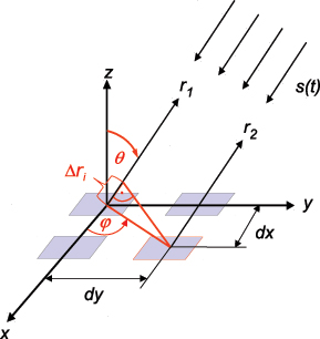
Figure 5 presents the geometry of a rectangular antenna array with 2×2 elements and a signal s(t) impinging from direction (ϕ, θ).
Figure 5. Parallel wavefront impinging on a rectangular array with 2×2 elements.
The spacings of the elements dx, dy are typically half a wavelength, but can also be less. The range difference for antenna element i relative to the reference element in the center of the coordinate system depends on the incident direction (ϕ, θ) and the position (m=0,1, n=0,1) of the element within the array:
(4)
The corresponding carrier phase shift is:
(5)
For CRPA and adaptive beam forming applications, the differential code delays may be neglected if they are small compared to the code chip length. However, it is essential that the carrier phase differences are precisely simulated, because they contain the information about the incident direction of the signal and are the basis for the array processing in the receiver. For instance, the receiver can estimate the directions of arrival of the incident signals from these carrier phase differences.
Now we consider a 2×2 array antenna. It can be simulated with the simulator with four RF outputs, where each output corresponds to one antenna element. In the simulator control software, a user with four antennas is set up, where the position of each antenna element is defined as an antenna position offset relative to the user position. In this approach, both differential code and carrier delays due to the simulated array geometry are taken into account, because the code and carrier pseudoranges are computed by the simulator for the position of each antenna element. However, the RF hardware channels of the receiver front-end may have differential delays against each other, which may even vary with time. If the direction of the satellites and interferers shall be estimated correctly by the receiver algorithms, a calibration signal is required to measure and compensate these differential hardware delays.
For the real antenna system, a binary phase-shift keying (BPSK) signal with zero delay for each antenna channel is generated by the array receiver and fed into the antenna calibration port. For the simulation, this calibration signal must also be generated by the constellation simulator.
In a simple way, a satellite in the zenith of the user antenna can be simulated, which has the same distance and delay to all antenna elements. Unfortunately, this simple solution includes some limitations to the simulated position and attitude of the user, because the user position must be at the Equator (if a “real” satellite is simulated in form of a geostationary satellite) and the antenna must not be tilted.
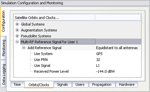
With a small customization of the simulator software, these limitations could be overcome. Figure 6 shows how to set up the generation of a reference signal. This reference signal can either be simulated as a transmitter directly above the user position, which follows the user position and thus allows also simulations offside the Equator, or simulated as a zero-range signal on all RF outputs, neglecting any geometry, which is the preferred method. The latter one is more or less identical to the reference/calibration signal generated by the receiver itself.
Figure 6. Configuration of a modulated reference signal.
The power level of this signal is held constant and is not affected by any propagation delay or attenuation simulated by the control center.
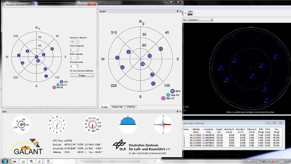
Attitude Determination
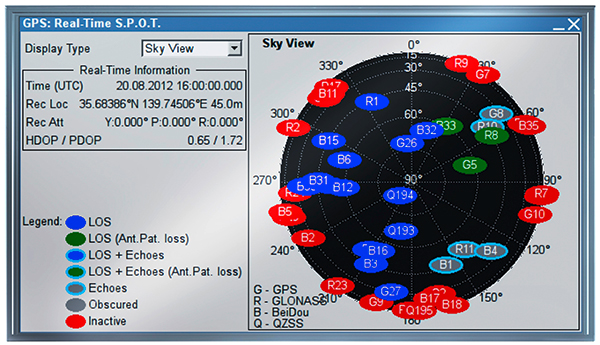
According to Figure 5, the phase difference measured between antenna elements is a function of the direction of arrival (DoA). Thus, the DoAs of the incident signals can be estimated from the phase differences. In the GALANT receiver, the DoAs are estimated by an EPSPRIT algorithm after correlation of the signals. Compared with the (known) positions of the GNSS satellites, this allows the estimation of the antenna array attitude. Figure 7 shows the sky-plot of simulated satellites as seen at receiver location (simulated on the right; reconstructed by the receiver from the decoded almanac in the middle and the DoA on the left). By comparison of the estimated DoAs of all satellites and the skyplot from the almanac, the attitude of the antenna is estimated (left). In addition, the attitude angles simulated by the simulator is given (right).
Figure 7. Simulating and estimating attitude with a multi-element antenna.
Simulation of Interference
It is possible to simulate some simple types of interference. Possible interference scenarios are:
Wideband Noise. By increasing the power of a single satellite of the same or another GNSS constellation, a wideband pseudo-noise signal can be generated. Using a geostationary satellite also enables simulating an interference source at low elevations and constant position. Use of power-level files also allow generation of scenarios with intermittent interference (switching on and off the interference) with switching rates up to 5 Hz.
CW or Multi-Carrier IF. By disabling the spreading code and navigation message, a CW signal can be generated. The simulator also allows configuration of subcarrier modulations. Without spreading code (or to be precise with a spreading code of constant zero) the generated signal will consist of two carriers symmetrically around the original signal carrier (for example, configuring a BOC(1,1) signal will create two CW signals at 1.57542 GHz ± 1.023 MHz, thus producing “ideal” interferer for the Galileo E1 OS signal.)
Depending on the number of Merlin modules per RF output, interference to signal ratios up to 80 dB could be realized, limited by a dynamic range of 40 dB within one module and additional 40 dB range between two modules. However, the maximum power level of one individual signal is currently limited to -90 dBm. If only one channel per module is used, the maximum power level of this single signal can be increased by another 18 dB (for example, by using one module solely for interference generation and another module for GNSS simulation).
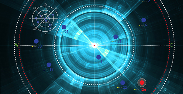
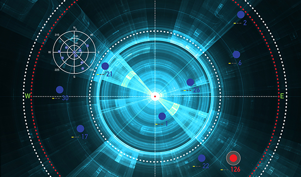
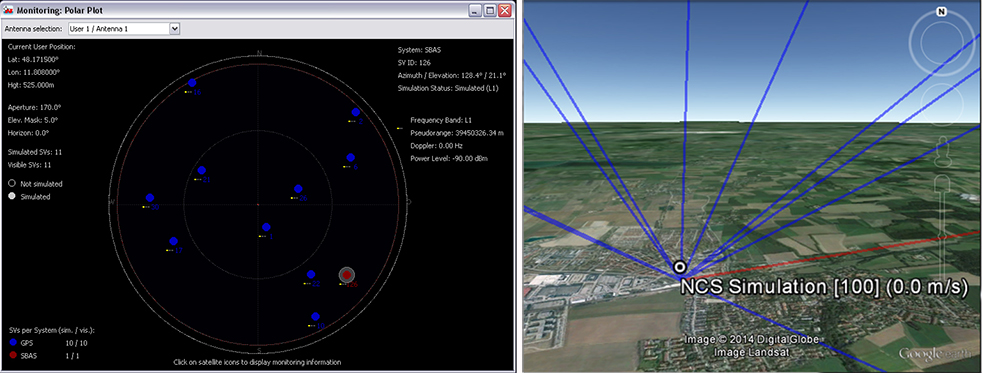
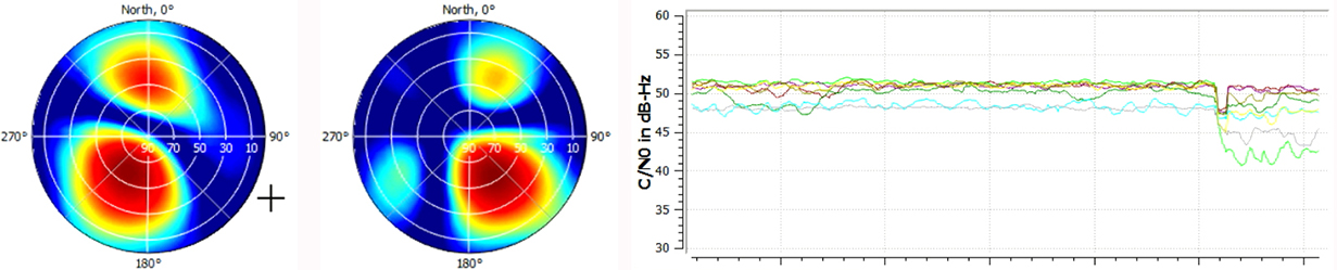
Figure 8 shows the simulated geometry for an interference scenario based on wideband noise generated by a geostationary satellite, producing –90 dBm signal power at the receiver front end. The interference source is very near to the direction of PRN 22 with a jammer power of –90 dBm, resulting in a jammer to signal ratio of J/S = 25 dB.
Figure 8. Geometry for the wideband noise interference scenario.
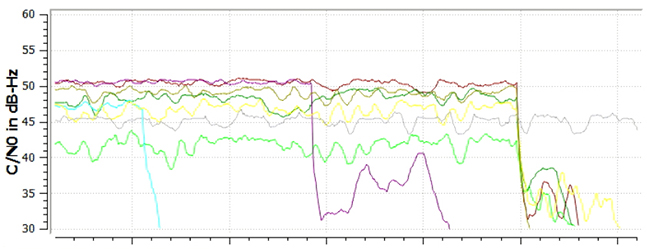
Figure 9 shows the two-dimensional antenna pattern as a result of the beam-forming before and after switching on the interferer. The mitigation algorithm tries to minimize gain into the direction of the interferer. As this also decreases gain into the direction of the intended satellite, the C/N0 drops by approximately 10 dB for PRN 22, because its main beam is shifted away from the interference direction. For satellites in other directions, the decrease in C/N0 is less: compare Figure9with Figure 10. However, the receiver still keeps tracking the satellite. After switching of beamforming, the signal is lost.
Figure 9. Beamforming for PRN 22 (light green line in lower plot) to mitigate for interference.Figure 10. Tracking is lost after switching off beamforming for individual channels (light blue, purple) and all channels (at the end of the plot).
Simulation of Spoofing
The simulation of a spoofing signal requires twice the resources as the real-world scenario, as every “real” LoS-signal must also be generated for the spoofing source. A simulation of an intentional spoofer who aims to spoof a dedicated position in this context is, however, very similiar to the simulation of a repeater ([un-]intentional interferer) device:
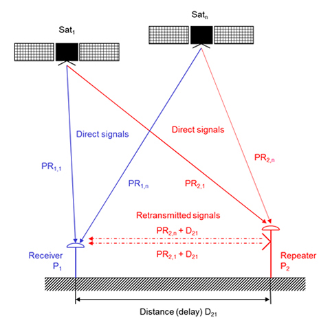
The repeater (re-)transmits the RF signal received at its receiver position. A receiver tracking this signal will generate the position of the repeater location but will observe an additional local clock error defined by the processing time within the repeater and the travel time between repeater and receiver position. A correct simulation for a multi-antenna receiver therefore has to superpose the code and carrier range as observed at the repeater location (considering geometric range between the transmit antenna of the repeater and the individual antenna elements) with the code and carrier ranges at the receiver location.
Instead of the location of the repeater P2, however, any intended location Px could be used to simulate an intelligent spoofer attack (Figure 11).
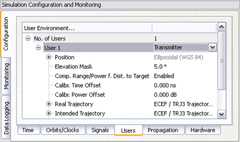
The simulator can generate such scenarios by configuring the position of the (re-)transmitting antenna and the intended position (for example, the position of the repeater). By calculating the difference between the real receiver position and the position of the transmitting antenna, the additional delay and free-space loss can be taken into account. The user may also configure the gain of the transmit antenna and the processing time within the repeater. Currently, this setup does only support one “user” antenna to be simulated. However, this feature combined with multi-antenna support will enable the simulator to simulate repeater or intelligent spoofer attacks in the future (Figure 12). To distinguish the “real” signal from the “repeated” signal, the “repeated” signal could be tagged as a multipath signal. This approach would allow simulation of the complete environment of “real” and “repeated” GNSS signals in one single simulator.
Figure 11. Geometry of repeater/spoofer and GNSS receiver.Figure 12. Simulator’s capability to simulate a repeater.
Manufacturers
The simulator producing the results described here is the NavX-NCS from IFEN GmbH. The simulator is valuable laboratory equipment for testing not only standard or high-end single-antenna GNSS receivers, but also offers additional benefit for multi-antenna GNSS receivers like the DLR GALANT controlled reception pattern antenna system.
The GNSS constellation simulator offers up to four phase-coherent RF outputs, allowing the simulation of four antenna elements with two carrier frequencies, each utilizing one single chassis being 19 inch wide and 2 HU high.
Simulation of intentional and unintentional interference is a possible feature of the simulator and allows receiver designers and algorithm developers to test and enhance their applications in the presence of interference to identify, locate and mitigate for interference sources.
Thorsten Lück studied electrical engineering at the universities in Stuttgart and Bochum. He received a Ph.D. (Dr.- Ing.) from the University of the Federal Armed Forces in Munich in 2007 on INS/GNSS integration for rail applications. Since 2003, he has worked for IFEN GmbH, where he started as head of R&D embedded systems in the receiver technology division. In 2012 he changed from receiver development to simulator technologies as product manager of IFEN’s professional GNSS simulator series NavX-NCS and head of the navigation products department.
Günter Heinrichs is the head of the Customer Applications Department and business development at IFEN GmbH, Poing, Germany.He received a Dipl.-Ing. degree in communications engineering in 1988, a Dipl.- Ing. degree in data processing engineering and a Dr.-Ing. degree in electrical engineering in 1991 and 1995, respectively. In 1996 he joined the satellite navigation department of MAN Technologie AG in Augsburg, Germany, where he was responsible for system architectures and design, digital signals, and data processing of satellite navigation receiver systems. From 1999 to April 2002 he served as head and R&D manager of MAN Technologie’s satellite navigation department.
Achim Hornbostel joined the German Aerospace Center (DLR) in 1989 after he received his engineer diploma in electrical engineering from the University of Hannover in the same year. Since 2000, he has been a staff member of the Institute of Communications and Navigation at DLR. He was involved in several projects for remote sensing, satellite communications and satellite navigation.In 1995 he received his Ph.D. in electrical engineering from the University of Hannover.His main activities are in receiver development, interference mitigation and signal propagation.
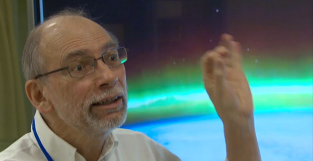
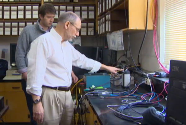
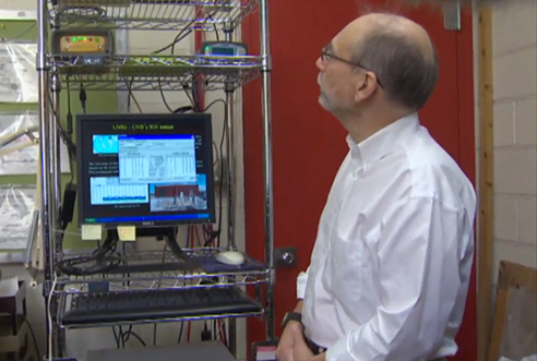
Langley, a professor at the University of New Brunswick, is working with the Jet Propulsion Laboratory in California to better understand how the ionosphere is disturbed by a variety of phenomena including solar outbursts and other natural hazards such as tsunamis. They are using the signals from GPS satellites to probe the ionosphere with the signals being picked up by receivers both on the ground and in low-Earth-orbiting satellites. The research could help find ways to mitigate ionospheric interference to GPS signals themselves as well as to other types of radio communications.
“GPS satellites are much higher than the ionosphere,” Langley told CBC News reporter Shane Fowler. “So the signals from the satellites have to come down through the ionosphere to receivers on or near the Earth’s surface. And as they come down through the ionosphere they get a little distorted. When you see auroras in the sky, that’s when you can tell the ionosphere is a bit disturbed. The average consumer may not notice these variances, but high-precision applications, like for scientific applications, we actually always see the effect of the ionosphere.”
Screen capture from CBC news video.
The research could also help develop early-detection systems for tsunamis. “The energy from that water displacement actually propagates up all the way into the atmosphere, all the way to the ionosphere,” Langley told CBC. “It basically moves around the electrons up there and GPS signals coming down from the satellites, through the ionosphere, pick up those small variations. It has the potential to save a lot of lives.”
Solar flares can also affect GPS signals. The Carrington Event, a solar storm in 1859, knocked out some of Earth’s telegraph systems. “The effect on the Earth’s magnetic field was so strong that currents were set up,” Langley told the CBC. “Those currents were so strong that telegraphs could run without batteries. There was enough current from this disturbance that it could run the telegraphs. And in some cases there was too much and rumour has it started small fires. Luckily we haven’t had one of those again; it seems to be a one-in-100-year, or a one-in-a-200-year, event.”
Special Section, March 2015. Download a PDF of this section, with the Simulator Product Showcase.
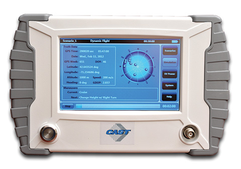
CAST Navigation
CAST-SGX GPS Satellite Simulator
The SGX GPS satellite signal simulator from CAST Navigation. Photo: CAST Navigation
The SGX GPS satellite signal simulator from CAST Navigation provides the user with dynamic, repeatable GPS RF signals for use in the laboratory or in the field for a wide range of GPS applications. The SGX simulator is housed in a portable, lightweight, handheld enclosure measuring 7 x 11 x 3 inches and weighing just over 4 pounds.
The SGX is lightweight and portable, operates on AC or battery power, and features 16 channels of L1 C/A and P codes. Based on CAST’s technology that has been developed for use in the company’s larger military products, it is extremely accurate and repeatable.
The SGX is controlled via an intuitive touchscreen interface that allows the user to select, start, and stop scenarios, change screen views, and change satellite RF power levels while a scenario is running. Three test scenarios are delivered with the simulator.
XGEN Plus Scenario Generation Software. This software gives the user the ability to generate custom scenarios for use with the SGX. The software allows for complete control over GPS almanac, ephemeris, and all satellite error sources.
The user can select from a variety of vehicle types and simulate static or dynamic motion. The user can also employ antenna gain patterns and vehicle silhouettes if desired. The user can generate a customized high precision six-degree-of-freedom trajectory simply by defining a mission profile that is based on raw maneuvers, waypoints, Google Maps or a combination of these maneuver types.The new scenarios can be downloaded via USB port or SD card interfaces.
CAST has been in the GPS simulation and support business for more than 30 years, designing, developing, manufacturing, and integrating innovative GPS/INS simulators and associated test equipment for government, military, prime vendor, and consumer markets.
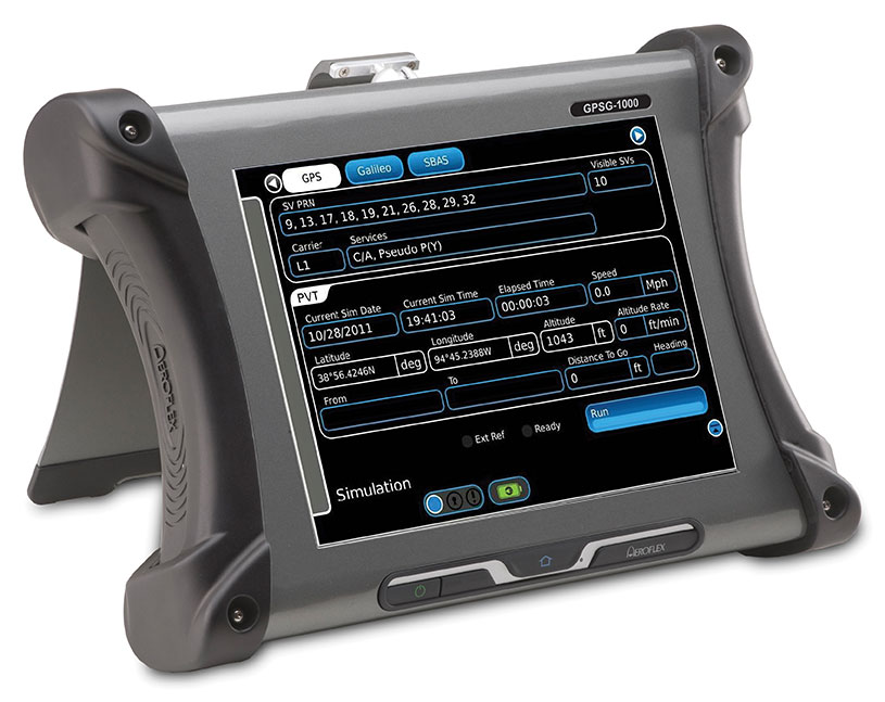
Designed to be a versatile yet affordable satellite simulator, the GPSG-1000 is proving to be a vital instrument used by those validating and testing GNSS receivers in a variety of applications within the transportation, consumer electronics, aerospace and military industry segments, to name a few.
The GPSG-1000 is a single carrier, multi-channel GPS/Galileo simulator that is portable and ruggedized so it can be safely and confidently deployed in a variety of outdoor and indoor environments. The unit is available in a 6- or 12-channel configuration, and supports the following GNSS signals: L1, L1C, L2C, L5, E1, E5, E5a, E5b and SBAS (WAAS and EGNOS).
The GPSG-1000 can be directly connected to a GNSS receiver under test. It can also simulate actual “open-sky” situations whereby the unit can generate its signals through the included antenna coupler system that isolates and transmits to the UUT’s antenna(s). Utilizing an integrated GPS receiver, the GPSG-1000 simulates actual time of day and date as well as the real constellation that would be available for navigation at that specific point in time. Multiple almanacs and route files can be saved to the GPSG’s memory, thereby enabling current and past history dynamic motion, constellation environment creation/recreation and other significant troubleshooting capabilities. During any given static or dynamic simulation, space vehicle parametrics and health can be user controlled.
The GPSG-1000 features a touchscreen user interface that can be remotely hosted via an integrated Ethernet port. The unit uses a rechargeable, Lithium Ion battery enabling hours of untethered use, and can also be used while the battery is recharging.
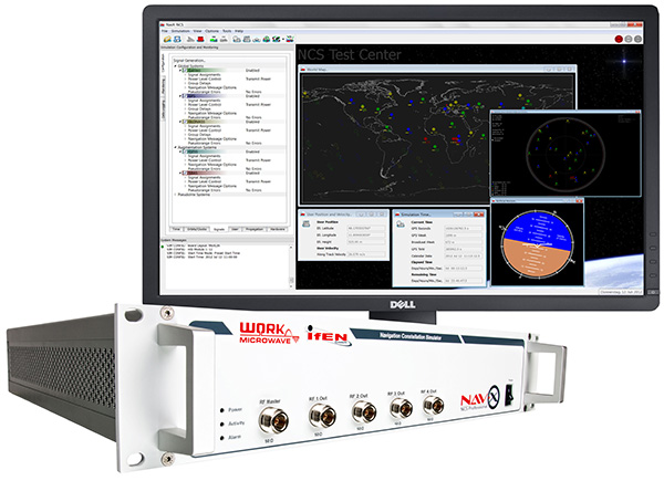
The NavX-NCS Professional GNSS Simulator by IFEN. Photo: IFEN
The absolute flexibility of the NavX-NCS Professional GNSS Simulator allows it to be configured with up to 108 channels and all of the following signals:
GPS L1/L2/L5 C/A & P code and L2C
GLONASS G1/G2 standard & high accuracy codes
Galileo E1/E5/E6 (BOC/CBOC/AltBOC)
BeiDou B1/B2/B3
SBAS L1/L5 (WAAS, EGNOS, MSAS, GAGAN)
QZSS L1 & L1-SAIF
IMES
The user is enabled to assign signals freely to any of the RF modules fitted to the simulator. This allows the same hardware to be used in a range of different configurations.
Signals may be added by software license with no need to return the hardware for upgrade.
Up to four independent RF outputs may be fitted, enabling the user to simulate multiple antenna locations simultaneously (allowing simulation of multiple antennas on one vehicle, multiple vehicles simultaneously, a mixture of static locations and mobile vehicles, and multiple antenna elements for Controlled Reception Pattern Antenna [CRPA] testing).
The comprehensive and easy-to-use Control Center operating software allows the operator to quickly create realistic test scenarios for effective testing of user equipment.
IFEN also offers the NavX-NCS Essential GNSS Simulator, which is available with 21 or 42 channels and is capable of simulating GPS L1 (including SBAS L1), GLONASS G1, Galileo E1, BeiDou B1, QZSS L1, and IMES. The simulator is also supplied with Control Center operating software for comprehensive scenario generation.
For USA and Canada: Mark Wilson; phone: 951-739-7331; email: [email protected]
Racelogic
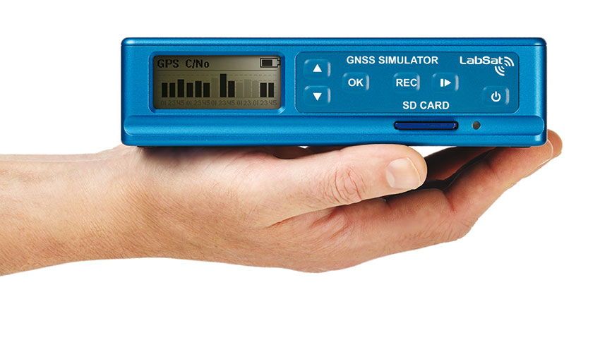
LabSat 3 Triple Constellation Simulator
RaceLogic LabSat 3. Photo: RaceLogic
LabSat 3 from Racelogic is a low cost, stand-alone, battery powered, multi-constellation RF record-and-replay device, designed to assist GNSS engineers in the development and testing of their products.
With its small size and all-in-one design, LabSat 3 makes it easier than ever to collect raw satellite data in the same environment that end users experience in everyday use. This enables repeatable and realistic testing to be carried out under controlled conditions.
LabSat 3 doesn’t need to be connected to a PC in order to record live-sky GNSS signals. With one-touch recording to SD card and a two-hour battery life, it can be used in any outdoor location to create real-world scenarios, for eventual replay back in the lab. As well as being able to simultaneously record or replay GPS, GLONASS, BeiDou, QZSS, Galileo, and SBAS signals, it can log CAN Bus, serial, or digital data, embedded alongside the satellite information. This additional information can then be replayed alongside the GNSS output, with synchronization to within 60 ns. A 1PPS signal can also be generated using the internal GPS receiver.
LabSat 3 can be used as a replay system out of the box with a set of 60 pre-recorded scenarios supplied as part of the package, recorded from various locations around the globe. Additionally, SatGen software, a demo version of which is available from the LabSat website, allows for
scenario generation of user-defined trajectories, with precise control over velocity, heading, height, and constellation profiles. Routes are also easily created in Google Maps, and the software also supports NMEA and KML file import. SatGen gives test engineers the ability to develop their products using simulations that would be difficult or impossible to record due to geographic location or safety constraints.
LabSat 3 is available as a record and replay, or replay-only version; either one, two, or three constellation types generate a single, dual, or triple constellation file.
LabSat is currently used by many leading manufacturers of GPS chipsets, portable navigation devices, smartphones, and by major car companies in their test, development and production processes.
www.labsat.co.uk; phone: +44 (0)1280 823803
Rohde & Schwarz
R&S SMBV100A: GNSS Simulator in Vector Signal Generator
The R&S SMBV100A: GNSS Simulator in Vector Signal Generator. Photo: R&S
The GNSS simulator in the vector signal generator R&S SMBV100A is designed for development, verification and production of GNSS chipsets, modules and receivers. The simulator supports all possible scenarios, from simple setups with individual, static satellites all the way to flexible scenarios generated in real time with up to 24 dynamic GPS, GLONASS, Galileo, BeiDou and QZSS satellites.
GNSS simulator with support of GPS L1/L2 (C/A and P code), GLONASS L1/ L2, Galileo E1, BeiDou and QZSS L1, including hybrid constellations.
Real-time simulation of realistic constellations with up to 24 satellites and unlimited simulation time.
Flexible scenario generation including moving scenarios, dynamic power control and atmospheric modeling.
Configuration of realistic user environments, including obscuration and multipath, antenna characteristics and vehicle attitude.
Static mode for basic receiver testing using signals with zero or constant Doppler shift.
Support of Assisted GNSS (A-GNSS) test scenarios, including generation of assistance data for GPS, GLONASS, Galileo, BeiDou and QZSS.
Real-time external trajectory feed for hardware in the loop (HIL) applications.
High signal dynamics, simulation of spinning vehicles and precision code (P-code) simulations to support aerospace and defense applications.
Enhanced simulation capabilities for aerospace applications by supporting ground-based augmentation systems (GBAS).
Support of other digital communications and radio standards in the same instrument.
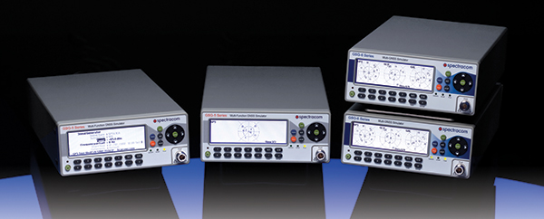
Afforable, Flexible and User-Friendly GNSS Simulators
The Spectracom family of simulators. Photo: Spectracom
Spectracom GNSS Simulators support test and development programs from simple manufacturing tests to multi-output testing across the diverse ecosphere of industries relying on GNSS technology. Spectracom’s innovation allows users of any skill level full control over the GNSS constellation, vehicle motion/attitude and signal path complications such as atmospherics and multipath to develop complex scenarios. Typical test conditions include:
Clock errors
Data errors
“Real-world” motion from embedded Google Maps
In-band noise generation
Multipath
Signal obstructions calculated from 3D building models
“Current time” simulation
Real-time HIL testing
Easy synchronization for multi-output testing
Automative download of the current almanac
Antenna pattern effects
Inertial sensor testing
Assisted GNSS testing
No dedicated PC is required. Scenarios are run and managed from the front panel, SCPI commands, or any PC/tablet via a web interface. Users can select a flexible, field upgradeable Spectracom simulator, and then purchase the software options they need.
GSG-6 Series multi-frequency, advanced GNSS simulator is powerful enough for any cutting-edge test program. GPS, GLONASS, Galileo, Beidou, QZSS and IRNSS signals are available across multiple frequencies. The GSG-6 is designed for military, research or professional applications.
GSG-5 Series multi-constellation L1-band GNSS simulator is designed for commercial development/integration programs. If a user is developing commercial products with GNSS capability, the GSG-5 will shorten test programs with confidence.
GSG-51 single channel signal generator is designed for one purpose — fast, simple go/no-go manufacturing test and validation, ensuring the manufacturing line is operating at full capacity with confidence in quality.
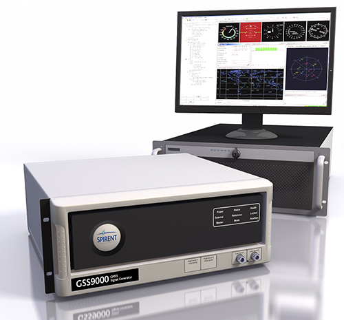
Spirent provides simulators that cover all applications, including research and development, integration/verification and production testing.
GSS9000. The newly released Spirent GSS9000 multi-frequency, multi-GNSS RF constellation simulator can simulate signals from all GNSS and regional navigation.The GSS9000 offers a four-fold increase in RF signal iteration rate (SIR) over Spirent’s GSS8000 simulator. The GSS9000 SIR is 1000 Hz (1 ms), enabling higher dynamic simulations with more accuracy and fidelity. It includes support for restricted and classified signals from the GPS and Galileo systems, as well as advanced capabilities for ultra-high dynamics. It can evaluate resilience of navigation systems to interference and spoofing attacks, and has the flexibility to reconfigure constellations, channels and frequencies between test runs or test cases.
Hardware changes can be done in the field, supported by the new on-board calibrator module. The GSS9000 is extensible and can support the widest range of carriers, ranging codes and data streams for the Galileo, GPS, GLONASS, and BeiDou systems, as well as regional/augmentation systems. Multi-antenna/multi-vehicle simulation, for differential-GNSS and attitude determination, and interference/jamming and spoofing testing are also supported.
CRPA Test System. Spirent’s Controlled Reception Pattern Antenna (CRPA) Test System generates both GNSS and interference signals. Users can control multiple antenna elements. Null-steering and space/time adaptive CRPA testing are both supported by this comprehensive approach.
GSS6425. The Spirent GSS6425 RPS quickly and simply records complex real-world RF environments, capturing both GNSS signals and atmospheric/interference effects. These environments can then be replayed repeatedly to the hardware software under test, reducing project, travel and engineering costs.
The Street View Trekker on a zipline in the Amazon Rainforest.
New imagery of the highest canopy in the Amazon rainforest is now available on Google Maps. The Amazon rainforest is one of the most diverse ecosystems in the world, with many species high in the canopies of the forest still undiscovered.
“Starting today, with the help of our partners at the Amazonas Sustainable Foundation (FAS), you can begin to unlock some of the wonders of the forest, by traveling from the upper canopy to the forest floor with Google Maps’ first zipline Street View collection,” wrote Karin Tuxen-Bettman, program manager, Google Earth Outreach on a March 1 blog.
The project is part of Google’s partnership with FAS, who three years ago invited Google Maps to the Rio Negro Sustainable Development Reserve. “Their hope is that sharing the imagery of their local communities, rain forests and rivers with the world will raise awareness and support for their efforts to conserve these areas,” Tuxen-Bettman writes.
The imagery was collected through Google Map’s Trekker Loan Program, which loans out the Street View camera and technology to tourism boards, non-profits, universities, and research organizations to help collect imagery of remote places.
The Amazon map imagery was gathered through boat travels on 500 kilometers of rivers, hiking on 20 kilometers of forest trails and ziplining through forest canopies.
“We hope it inspires you to embark on your own virtual expedition of the Amazon (you can leave the bug repellent at home!),” Tuxen-Bettman writes.
The map on this page shows where Google Maps has yet to collect Street View imagery.