The Trimble InSphere Data Manager provides efficient geospatial data management for an entire organization.
Trimble has introduced a new Data Marketplace service for the Trimble InSphere geospatial information management platform. The InSphere Data Marketplace allows geospatial professionals to quickly search, locate and obtain spatial data on demand. InSphere users can now find and use additional free and premium spatial data layers, including aerial and satellite imagery, terrain, elevation and topographic maps, building footprints and other third-party data. In addition, new capabilities have been added to a variety of InSphere applications to streamline geospatial data access.
“As the latest addition to the InSphere platform of applications, the Data Marketplace service plays an important role in our cloud-based geospatial information management platform. InSphere’s Data Marketplace is designed to help our customers find, manage and use spatial data critical to their business,” said Alain Samaha, business area director of software for Trimble’s Geospatial Division. “Giving our customers access to multiple layers of spatial information makes end deliverables more robust for their clients.”
The Trimble InSphere Data Marketplace is a new application that is part of Trimble InSphere, a cloud-based platform of software, data, and services focused on the needs of geospatial professionals including surveyors, engineers and GIS professionals. InSphere’s web interface provides access to other productivity-enhancing applications such as Trimble InSphere Data Manager, Trimble InSphere Equipment Manager, Trimble TerraFlex and Trimble Access Services.
The latest release also adds capabilities and enhancements to the applications within the InSphere platform:
Trimble TerraFlex — Unified Geospatial Data Collection and Simplified Digital Forms
The TerraFlex application includes productivity enhancement features that enable a tighter integration for Esri’s ArcMap plugin and allow GIS users to bring in data directly from TerraFlex into an ArcMap project. The module includes Esri basemap support for access to a range of freely available Esri basemap layers, new export options for more flexibility for portable data formats, exchange, and full Windows 7 and 8 support on TerraFlex Mobile. This enables users a broader range of devices to select and use in the field for collecting asset information data. In addition, the TerraFlex user interface is now integrated into the Trimble InSphere platform, giving users a seamless experience between TerraFlex and other InSphere modules. A 30-day free trial is available online.
InSphere Data Manager — Geospatial Information in One Place
Data Manager now supports Trimble Business center version 3.2 files, increasing support for more data file formats that a user is able to upload and view within the module. A 90-day free trial is available online.
The release expands the compatibility to add and manage more devices faster and easier. Users can now import a list of devices from an Excel spreadsheet to immediately begin managing devices in the module. In addition, Equipment Manager now supports Trimble Access Software version 2013.40 (and higher), increasing the number of devices that a user can manage. A 90-day free trial is available online.
Scientists and engineers of the GNSS persuasion will want to test their knowledge of the two-body model and Keplerian orbits in a practical application at the roulette wheel in GPS World’s booth, #224–#226, at the ION GNSS+ Conference.
Those successful in their predictions of the fall of the ball will mathematically increase their chances of winning a Go-Pro Hero video camera, a pair of tickets to the fabulous Leadership Dinner, or a bevy of $50 gift cards.
Simply fill out a subscription form and receive five chips for play at the roulette table. Bet odd or even, red or black; bet your favorite number or take a split. If the ball falls into the 0, 00, or 25 slots, all bets on the table, winning or losing, are paid off with a handsome additional stake! This is the magazine’s way of celebrating its 25th anniversary.
The more you win, the more raffle tickets you can put into the drawing bowl for the prizes. The prize drawing will be held during the afternoon break on Thursday, at approximately 3:40.
According to a well-known GNSS expert and ION attendee, “From the point of view of satellite orbital mechanics, the high-speed spinning of a ball within the outer rim of a roulette wheel resembles the orbit of a satellite around a massive body. Friction between the wheel and the ball generates orbital decay that causes the ball to lose speed and, once a certain loss of energy occurs, fall from the rim into the center of the wheel. In the case of roulette, timing the period of motion of both the ball traveling around the rim and the wheel in the center combined with an orbital decay model allows a computer to predict the correct quandrant of the wheel that the ball will settle into as much as 40 percent of the time. Properly implemented, this is enough to create a tremendous advantage over the casino.”
You too can turn your scientific knowledge to lucrative advantage!
GPS World Booth #224–#226 is located at the rear of the hall, adjacent to the attendee lounge. The roulette wheel will be in operation during all exhibit floor hours, including the Wednesday evening reception.
A new event highlighting indoor location is being held this year at the ION GNSS+ Conference, which takes place September 9-12 in Tampa, Florida. The two-part event is scheduled for Wednesday, September 10.
The indoor location sessions are part of a new Commercial Track that also covers high-accuracy products, multi-constellation products, new consumer products such as wearables, MEMS, and simulation and testing.
The discussion will cover issues of standardization and certification from key organizations involved in indoor location, according to the ION GNSS+ program. Discussion will focus on the progress and issues for bringing indoor location to a level of standardization to allow penetration into all mobile devices.
Panel members include:
3GPP: Kirk Burroughs, Qualcomm
WiFi Alliance/IEEE: Marc Linsner, Cisco
Bluetooth Sig/OMA: Ian Blair, Cambridge Silicon Radio Ltd., UK
FCC/CSRIC: Chris Gates, Nextnav
Multiple: Steve Malkos, Broadcom
OGC: Hongwei Liu, MappedIn, Canada
MEMS Industry Group: Mahesh Chowdhary, ST Microelectronics
In-Location Alliance (ILA): Jounni Kamarainen, Nokia, Finland
Paul McBurney, GopherHush Corp., is guiding live indoor location demonstrations from 3:55 to 5:30 p.m. in Room 13-16. Demo areas will be set up around the edge of the conference room, and each presenter will have their demo running. In turn, each will talk about their demo from the stage. At the same time, there will be live video of the demo feeding to the big screen on stage. After the demos, panelists will be seated on stage to answer questions posed by the chair, and audience question moderated by the chair.
Demonstration partipants include:
RxNetworks, Ryan Reilly, “Resolving Indoor Location on Three Axes Using A-GNSS/Wi-Fi/ and Barometric Pressure”
Broadcom, Steve Malkos, “Enhanced Wi-Fi Ranging with Round Trip Time Measurements”
CSR, Dave Huntingford, “Indoor Positioning with MEMS, GNSS, Wi-Fi, Signals of Opportunity and Cloud-Based Learning”
PNI Sensor, Becky Oh, “Pedestrian Dead Reckoning (PDR) Using MEMS Inertial Sensors and PNI Sensor’s Ultra Low-Power SENtral Sensor Hub”
Indoo.rs, Markus Krainz, “Indoor Location Demonstration”
Navizon, Inc., Cyril Houri, “Navizon Indoors: A Pedestrian Navigation System Combining the Analysis of Wireless Signals (Wi-Fi, iBeacons) and Inertial Navigation”
Nokia, Jani Ollikainen and Hannu Laine, “Indoor and Local Positioning with BT Low Energy and Easy Installation”
ION GNSS+, sponsored by The Institute of Navigation, is considered the world’s largest technical meeting and showcase of GNSS technology, products and services. This year’s conference takes place September 8-12 at the Tampa Convention Center in Tampa, Florida.
ION GNSS+ will bring together international leaders in GNSS and related positioning, navigation and timing fields to present new research, introduce new technologies, discuss current policy, demonstrate products and exchange ideas.
Pre-conference events held Monday and Tuesday, September 8-9, include tutorials and the CGSIC meeting. The conference itself kicks off Tuesday with the plenary session, held 6:30-8:30 p.m.
This year, the plenary speaker is Tristan Gooley, navigator and explorer, who will discuss “The Wonderful World of Natural Navigation.” Gooley has led expeditions in five continents, climbed mountains in Europe, Africa and Asia, sailed small boats across oceans and piloted small aircrafts to Africa and the Arctic. He has walked with and studies the methods of the Tuareg, Bedouin and Dayak in some of the remotest regions on Earth. Gooley will describe how his love of the subject grew over time and explains how he learned to find his way using the sun, moon, stars, weather, plants and animals. He has used natural navigation in the Sahara desert, in jungles, on ice, on oceans and in the English countryside. He will explain how these ancient techniques can be used by anyone willing to try something new and how natural navigation can enrich all journeys, large or small.
Gooley’s talk will be followed by Panel Discussion Lightning Talks moderated by GPS World Publisher Alan Cameron. Presenters include Dr. John Betz, The MITRE Corporation; Didier Faivre, European Space Agency, France; Dr. Frank van Diggelen, Broadcom; Glen Gibbons, Inside GNSS; Oscar Pozzobon, QASCOM S.R.L., Italy; Dr. Frank van Graas, Ohio University; Dr. Todd Humphreys, The University of Texas at Austin; Dr. Dorota Grejner-Brzezinska, The Ohio State University; and Dr. Didier Flament, European Space Agency, France.
Technical sessions will be held Wednesday, Thursday and Friday. This year, a new commercial track has been added.
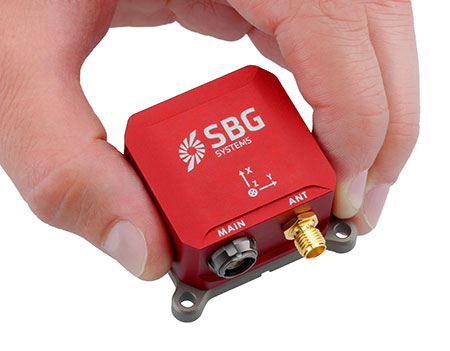
SG Systems’ IG-500 Series of miniature inertial sensors. Photo: SBG Systems
SBG Systems has released the Ellipse Series, a product range of miniature inertial systems replacing the IG-500 Series. For the same budget, customers benefit from higher accuracy, advanced filtering and features of high-end inertial navigation systems, the company said.
The Ellipse Series of miniature inertial systems benefits from a new design, new sensors, new capabilities, and new algorithms. “We have selected state-of-the-art MEMS sensors, especially very low noise gyroscopes that greatly enhance Ellipse performance. We integrated cutting-edge GNSS receiver while keeping a small size,” said Alexis Guinamard, CTO of SBG Systems.
“We are able to upgrade miniature sensors capabilities by injecting some advanced and proven filtering and features inspired from high end inertial navigation systems,” Guinamard said. Besides higher accuracy, SBG Systems added for the same budget an improved FIR and rejection filtering, robust IP68 enclosure, high output rate, RTK corrections, and automatic alignment.
Weighting from 45 grams, Ellipse sensors are flexible. The Ellipse-A model provides 3D orientation and heave. For navigation, users can connect their own GPS receiver with the Ellipse-E, or use an internal receiver by choosing the Ellipse-N model. The larger Ellipse-D integrates a survey-grade L1/L2 GNSS receiver with two antennas for heading and position accuracy.
Ellipse A, N, E models are available for order now. The Ellipse-D model will be available in the first quarter of 2015.
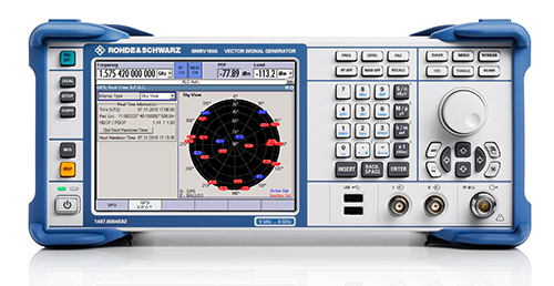
Rohde & Schwarz will be demonstrating its SMBV100A simulator at ION GNSS+ 2014, and is offering a new Wireless Standards poster for visitors to its booth. Rohde & Schwarz will be exhibiting in Booth I during the show, which will be held in Tampa, Florida, September 10-11.
Based on a digital vector signal generator, the SMBV100A supports realtime and hybrid configurations up to 24 dynamic GPS, GLONAS, Galileo, BeiDou and QZSS satellites and can be synchronized for multi-channel RF solutions. Rohde & Schwarz will be demonstrating its latest SMBV100A solutions and technologies along with dedicated solutions to support navigation and GNSS testing including:
Support realistic user environments: obscuration, multipath, antenna characteristics and vehicle attitude
Realtime external trajectory feed for hardware in the loop (HIL) applications
High signal dynamics, simulation of spinning vehicles and precision code (P code) simulations
Support for ground-based augmentation systems (GBAS)
Avionics test solutions: VOR, ILS, DME, and TACAN
Field-to-lab capture and playback solutions
Interference hunting and direction finding solutions
New Wireless Standards Poster – Register Now!
Conference attendees who stop by Booth I can register for a new Wireless Standards Poster. The convenient wall chart provides an overview of all the major standards for digital cellular, public safety, TV white space, wireless connectivity and GNSS technologies.
Not able to attend? Click here to register to have a poster sent to you.
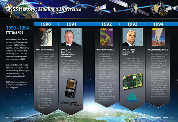
GPS World’s 25th Anniversary GNSS History Timeline, from the September 2014 Special Supplement “GNSS Industry: Past, Present, and Future.” Download the PDF.
This integrated circuit supports simultaneous reception and processing of the GPS L1/L5, Galileo E1/E5a, and GLONASS G1 signals with 40 tracking channels. The dual-band analog RF front-end is integrated on the same mixed-signal chip as the baseband hardware, including an embedded processor to close the tracking loops: overall, a compact, low-power, and low-cost solution.
By Fabio Garzia, Stefan Köhler, Santiago Urquijo, Philipp Neumaier,Jörn Driesen, Sybille Haas, Thomas Leineweber, Tao Zhang, Sascha Krause, Frank Henkel,Alexander Rügamer, Matthias Overbeck, and Günther Rohmer
Multi-constellation multi-band global navigation satellite system (GNSS) receivers can efficiently exploit the advantages derived from the modernization of existing GNSS constellations, such as GPS and GLONASS, as well as from the launch of new ones like Galileo and BeiDou. Utilizing multiple systems can significantly improve the availability of a navigation solution in urban canyons and heavily shadowed areas. Increased satellite availability also guarantees higher measurement redundancy and improved reliability. Moreover, the excellent inherent noise and multipath mitigation capabilities of the new and modernized wideband signals in the L5/E5a band, combined with the ionosphere error mitigation given by frequency diversity, significantly improves the accuracy in both measurement and position domains.
Still, most commercial fully-integrated single-chip mass market GNSS receivers use only a single-frequency band for their positioning, velocity, time (PVT) solution: either GPS L1 C/A or Galileo E1 and GLONASS G1. For example, the Teseo chips are single-chip solutions that support multiple constellations but only on one frequency band. This approach reduces design costs and enables the lowest consumption of power, but neglects the advantages of wideband signal processing – which offers increased robustness thanks to two simultaneous frequency band receptions and the capability of mitigating the ionosphere error.
Another approach for realizing multi-constellation multi-frequency solutions is to combine different chips for the analog front-end and the digital baseband. One fully integrated single-chip analog multi-band front-end for the simultaneous reception of GPS L1/L5, Galileo E1/E5, and GLONASS has been presented. However, this chip included only the front-end and requires an additional, separate digital-baseband solution.
The purpose of the NAPA project (NAvigation chip for Pedestrian navigation and higher precision Applications) is to close this gap by providing a fully integrated, compact, low-power, and low-cost solution in which the analog and digital parts of the GNSS receiver are integrated together on the same chip. The NAPA receiver offers all the advantages of multi-constellation reception with additional dual-frequency support.
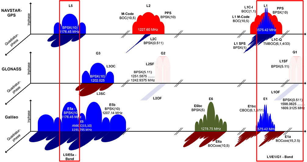
The NAPA chip features a monolithic, single mixed-signal chip implementation of a multi-system, multi-band analog front-end and the related digital baseband core, including an embedded processor. The NAPA chip can be used as a stand-alone GNSS sensor, because no additional components are required to obtain a PVT solution. The ASIC was implemented in a low-power technology and adopts some ad-hoc low-power architectural features. In regard to costs, an ASIC solution is more convenient than FPGA, provided the non-recurring engineering costs (NRE) are amortized by the amount of chips manufactured and sold. The NAPA chip supports multi-system (GPS, Galileo, and GLONASS) and multi-band (GPS/Galileo L1/E1, L5/E5a, GLONASS G1) processing. Figure 1 shows the frequency band being selected for receiving and processing in the NAPA chip. With two fully deployed GNSS — GPS and GLONASS — NAPA chips can already be used in many commercial applications. Thanks to the spectral overlay of the GPS L1/L5 and Galileo E1/E5a signals, the chip is also ready for Galileo. The frequency selection features both the narrow-band legacy signals L1/G1, which can be used for fast acquisition. For highest tracking accuracy, the wideband GPS L5 and Galileo E5a BPSK(10) modulated signals can be utilized.
Figure 1. GNSS signals received and processed by the NAPA chip.
The higher accuracy is obtained primarily by the attenuation of the ionospheric error. The ionosphere is a dispersing media that can introduce a bias error between 1 and 20 m. Forming a linear combination of two independent frequency-band measurements, the ionospheric bias can be measured and almost completely removed. In addition, Precise Point Positioning and Wide/Narrow-laning combinations are possible, thanks to the second received frequency band. The first allows for the combination of precise satellite positions and clocks with multi-frequency measurements, providing cm/dm solutions. The second adopts fast ambiguity solutions for carrier-phase positioning and cycle-slip detection.
In this article, we present the NAPA chip in detail. We describe the architecture of the analog front-end and its digital counterpart and the innovative features of each. Then we provide details about chip implementation, manufacturing, and test setup. Finally, we present the first verification results and draw conclusions.
Architecture Overview
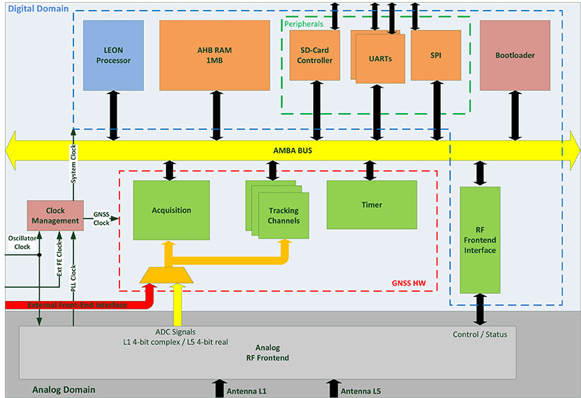
The NAPA chip architecture, depicted in Figure 2, is composed of two separate blocks integrated on the same silicon die: the analog core provides the functionality of a two-frequency radio-frequency (RF) front-end, whereas the digital part implements the main GNSS processing tasks, including the correlator channels and an embedded processor, and takes care of the RF front-end control. The interface between the two blocks is completely digital and provides synchronizers to ensure a valid clock domain crossing (CDC).
Figure 2. Overall NAPA architecture with emphasis on the digital core blocks.
Analog Front-End. The analog RF front-end supports the simultaneous reception of GPS L5 / Galileo E5a and GPS L1 / Galileo E1 / GLONASS G1 signals as well as modes where only one reception path is activated.
Both passive and active GNSS antennas are supported, thanks to integrated low noise amplifiers (LNA). There are two separate signal reception paths for the two frequency bands. The L1/E1/G1 path is characterized by a quasi-zero-IF conversion that mixes the middle frequency between L1/E1 and G1 to zero frequency. The L1/E1 reception bandwidth is up to 14 MHz so as to incorporate the MBOC modulations of Galileo E1 and future GPS L1C signals. A programmable automatic gain control (AGC) controls the complex analog baseband signals before they are digitized with a 4-bit dual-channel analog digital converter (ADC).
The second reception path receives an L5/E5a signal with up to 20 MHz bandwidth for the BPSK(10) modulated signals. This path uses a low-IF architecture. The signal is down-converted to an intermediate frequency (IF) of 15.345 MHz. The image frequency is suppressed by a polyphase filter. The real-valued analog signal is controlled by an AGC and converted to the digital domain using a single 4-bit ADC. A common phase locked loop (PLL) is used with specific L1/E1/G1 and L5/E5a dividers to generate the mixers’ local oscillator (LO) frequencies. The PLL loop filter is integrated on-chip to minimize external elements. Moreover, automatic filter and voltage-controlled oscillator (VCO) calibrations are included to mitigate process tolerances. The PLL can handle input clock frequencies between 10 and 80 MHz with a recommended clock frequency of 36.115 MHz.
An SPI core was implemented on the front-end part to facilitate control of the different front-end features. This means it is possible to tune the PLL, to switch off a complete front-end path if the second frequency band is not used and to activate different on-chip calibration procedures.
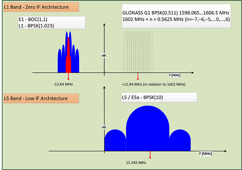
The frequency plan of the front-end is depicted in Figure 3. Due to the quasi zero-IF architecture, the complex L1/E1 baseband signal is located on an IF of -13.64 MHz and the GLONASS G1 frequency division multiple access (FDMA) signals on an IF of +12.94 MHz, with respect to the GLONASS G1 center frequency of 1602 MHz. The real-valued L5/E5a signals are provided by the second ADC and located on an IF of 15.345 MHz.
Figure 3. RF front-end frequency plan.
The ADC samples are generated with a frequency of 74.4871875 MHz for both the single channel L5, as well as for the dual-channel L1/E1/G1 ADCs. The ADC clock is also directly connected to the baseband digital core and is used as the main clock for the GNSS hardware modules. The embedded processor in the digital core receives a second clock, which is twice as fast as the GNSS hardware one.
Digital Baseband SoC. The baseband is characterized by a system-on-chip (SoC) architecture based on a SPARC-compatible 32-bit LEON2 microprocessor running at approximately 150 MHz. The GNSS functionality, including acquisition and tracking, are implemented using dedicated hardware modules.
The processor’s primary functions are to correctly configure the RF front-end and control the different parts of the receiver. In particular, it triggers acquisition, initializes, and starts the tracking channels with the signals detected during acquisition and takes care of closing the frequency/phase/delay locked loops (FLL/PLL/DLL) used for signal tracking. The tracking loops have strict real-time constraints; communication between the channels and the processor features a high-speed infrastructure.
Structurally, the processor is connected to a hierarchical on-chip Advanced Microcontroller Bus Architecture (AMBA) composed of a high-performance bus (AHB) and a peripheral bus (APB). The AHB provides a direct connection between the processor, the real-time GNSS modules, and the system memory, a monolithic 1 MByte block that hosts the main program at run-time. Different programs can be loaded if needed by using the external SD-card interface.
In addition to the processor, there are four additional AHB masters: the bootloader, the SD-card controller, the real-time GNSS modules, and the on-chip processor debugger. The bootloader is in charge of the bus control at system start-up. The SD-card controller has integrated direct-memory access (DMA) capabilities to move data between the SD card and the system memory. The real-time GNSS modules can write the tracking results directly to the system memory. Finally, the integrated processor debugger allows real-time debugging and is used mainly in the verification phase. The APB provides a connection to generic peripherals, and control and status interface of the GNSS modules without real-time constraints, as well as the control and status interface of the RF front-end. Since the GNSS modules operate in a separate clock domain that runs at half the frequency of the processor domain, some synchronization logic is necessary to ensure correct CDC.
The adoption of an SoC architecture provides higher flexibility than conventional static hardware solutions. In addition to typical GNSS applications, the user can also implement some signal monitoring and processing algorithms in software. The eCos-embedded operating system is provided to ease software development.
Generic Peripherals. The digital core is equipped with several peripherals that enable the communication with the outside world. The two separate universal asynchronous receiver/transmitter (UART) interfaces can run at 115.2 kbps. A dedicated serial peripheral interface (SPI) master is also provided with a maximum of 10-MHz clock frequency. For example, these interfaces can be used to provide NMEA data to some external display device or raw data (pseudoranges, code phases) in order to calculate a PVT solution. It is also possible to directly access the measurements generated from the correlator hardware and to control the tracking NCOs, which means users can choose their own algorithms for the loop closure. A possible application is the realization of vector-delay tracking using the NAPA ASIC and an external processor.
The SD-card interface facilitates the loading and storage of large amounts of data, for example, memory codes and almanacs. The possibility of making signal snapshots periodically and saving them to an SD card for later analysis has also been foreseen. This could be useful in special applications in which the receiver hardware is not accessible to the user all of the time.
In addition, 10 general-purpose I/O pins (GPIO) are provided. They can be controlled via software and can provide a very basic interface (for example, to connect to external LEDs or switches).
Acquisition Module. The acquisition module adopts a parallel code phase search in the Fourier domain by using a 16-k Samples Fast Fourier Transform (FFT) core. The adopted algorithm is known as parallel code-phase search.
The L1/E1/G1 signals coming from the front-end are first filtered and then sent to the acquisition module to allow a fast detection of the satellites in the L1/E1/G1 bands with their respective code delays and Doppler frequencies. The acquisition of GLONASS G1 FDMA signals is possible thanks to a software-configurable hardware mixer that can be set with the different G1 carrier frequencies. No direct hardware acquisition is supported for the L5/E5a band signals. The tracking of L5/E5a band signals is possible by performing a hand-over from L1/E1 band or a Tong search using the tracking channels.
The acquisition process is performed iteratively over all the possible satellites and over a set of Doppler values. These values are obtained by dividing the complete range of possible Doppler variations into bins. The smaller these bins are, the more accurate the acquisition result, but the more time is required to complete the entire process.
The acquisition has an additional layer of configurability because of the adoption of coherent and incoherent accumulations. These accumulations are supported in hardware but are completely software-controlled. This provides another possibility for achieving higher accuracy, but at the cost of a larger execution time due to an increase in the amount of accumulations.
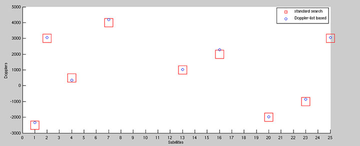
To speed up acquisition, we introduced a dedicated logic based on a novel patented algorithm. With this algorithm, we are able to detect the Doppler of the L1/E1 satellites present in the signal with an accuracy of 2 Hz. By performing this Doppler search step before the actual acquisition, we are able to generate a list with Doppler values that can be used instead of the bins. This gives more accurate results thanks to the algorithm’s inherent accuracy (see Figure 4) and allows a reduction in the acquisition time since the amount of Doppler values are usually smaller than the bins. Another advantage of this algorithm is the possibility to detect the transition to an indoor context (such as where there is a lack of satellite signals) by simply looking at the Doppler list, without performing any acquisition.
Figure 4. Comparison between standard and Doppler-list based acquisition of an L1 signal.
A single iteration step for the acquisition of a GPS L1 signal requires no more than 1 ms for each accumulated epoch. To achieve a good compromise between accuracy and speed, we typically use four epochs of incoherent accumulation, which means approximately 4 ms execution time. For Galileo L1 with four incoherent accumulations, an iteration step takes approximately 16 ms. This time has to be multiplied by the number of satellites and bins to estimate the execution time of the complete process.
Integrated Acquisition Memories. The acquisition module is characterized by dedicated memory blocks used for the fast FFT processing. It also provides the possibility to use these on-chip memories to store a snapshot of the incoming signals. In particular, we can store up to 81,920 samples of raw data for the complex L1 and real L5 IF signals for further analysis or processing, even off-chip. This enables sophisticated spoofing detection methods, for example, as well as interferer detection and characterization methods. Spoofing detection can be implemented by monitoring the 2D-acquisition search space. Interferer detection and characterization can employ short-time Fourier transforms (STFT) on the snapshot.
Using the chip as a simple snapshot receiver without having to use the on-chip dedicated GNSS hardware is also a possibilty. For this purpose, the integrated peripherals like UART and SPI ports are provided as interfaces.
Tracking Module. The 40 versatile tracking channels can be mapped to any combination of GPS, Galileo, and GLONASS signals on the two reception bands. One possible combination would be to track 10 GPS and 10 Galileo satellites simultaneously on both L1/E1 and L5/E5a bands. Alternatively, the user can include GLONASS signals by using fewer GPS / Galileo combinations. The assignment of these tracking channels to the actual GNSS signals can be changed at run-time in order to adapt to different reception situations or to assist the selected signal processing methods.
Each channel is characterized by a five-tap correlator. For the BPSK modulated signals without side peaks, such as GPS L1/L5, Galileo E5a, and GLONASS G1, we use only three values (early, late, and prompt). For Galileo E1 BOC(1,1) signals, five values are foreseen (very early and very late in addition to the previous), so that false peak lock conditions can be detected and a bump-jumping algorithm can be applied. The switch between these modes can be done at run-time and determines the amount of correlation values to be exchanged between correlators and processor.
Low-Power Features. The GNSS modules operate in their own clock domain. This clock domain is divided in clock-gated regions. There is a common region for the bus interfaces, one region for the acquisition, and one for each tracking channel. This allows a fine-grain shut-down of the GNSS modules that are not currently in use. For example, the acquisition can be deactivated when there are enough signals in tracking or the unused tracking channels can be disabled. This allows a reduced power consumption for the idle modules. This activation/deactivation procedure is controlled through a set of registers connected to the APB and is performed via software.
External Front-End Interface. To allow for more flexibility, we provided an additional RF front-end interface. The interface is also depicted in Figure 3. This interface features one 2-bit complex and an additional 2-bit real input, as well as a clock input. The user can decide to directly connect the digital baseband core to an external RF front-end with compatible sampling rate parameters, and exclude the on-chip RF front-end. This makes it possible to use the NAPA chip for validating other RF front-end devices, or it can be adapted to special customer needs.
Boot-Up Sequence. The SoC includes a hard-coded bootloader that is in charge of the bus control at start-up. In this phase, the processor is switched off. The bootloader loads a 24-kByte program from the SD-card to the system memory and starts the processor. In this phase, the processor runs with the external oscillator clock. Having performed the RF front-end initialization, the processor can switch to the front-end PLL generated processor clock that runs at approximately 150 MHz. This switch is completely transparent to the processor. Then the actual main GNSS receiver program is loaded into the system memory and executed.
The NAPA Chip
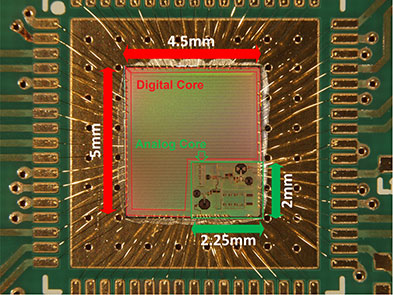
The NAPA chip has been manufactured in a low-power 1.2 V 65 nm TSMC technology. The 4.5 mm x 5.0 mm chip die was mounted in a QFN68 package; first test samples are available. The core requires a 1.2 V power supply, the pads 1.8 V. Figure 5 shows a picture of the die and its interconnections. The two parts, the analog core and the digital baseband, are clearly distinguishable. The chip is currently in the verification phase.
Figure 5. NAPA chip.
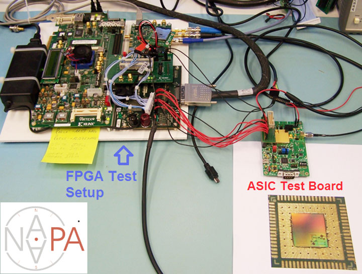
Within the project, the development and testing of the NAPA design was carried out on basically two platforms. During the hardware development phase, the baseband core has been prototyped on a FPGA device and tested using a special file-player setup, as explained in the following section. Having taped out the chip and received the first samples from the foundry, a test board has been developed in order to verify NAPA chip functionality.
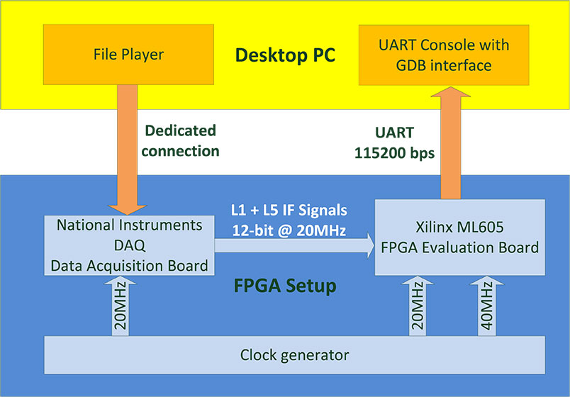
FPGA Test Setup. In the development phase, the NAPA baseband core has been implemented on a Xilinx Virtex6 FPGA device. A Xilinx ML605 development board has been used for the test setup. The main limitation of the testing in this phase was the lack of an analog RF front-end prototype. In order to make early testing of GNSS functionality possible, we adopted a file player developed by Fraunhofer IIS in a previous project. This file player uses a desktop PC to reproduce a digital signal data-stream stored in a binary file on the PC. The stream is sent through a dedicated interface to a commercial digital acquisition board. This board receives a clock synchronized with the baseband core’s clock in the FPGA and delivers the signals directly to the FPGA pins. The complete setup is depicted in Figure 6. The setup in use can be seen on the left part of the opening figure.
Figure 6. FPGA test setup.
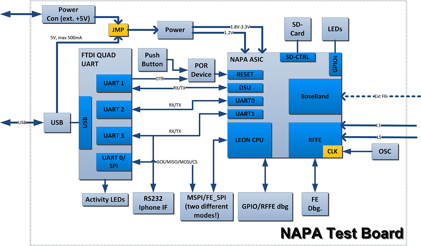
Test Board. In the verification phase, which is currently ongoing, the first unpackaged test chip dies have been glued directly to the test PCB and bonded on board without any housing. After receiving the packaged chips, the QFN68 could be regularly soldered on the PCB. A block diagram of the board is depicted in Figure 7. The board hosts the typical switch buttons and LEDs for quick control and status detection as well as some specific interfaces. The clock can be provided through a dedicated SMA clock connector as well as a discrete oscillator. Two sub-miniature push-on (SMP) connectors are also provided for separate the L1 and L5 antenna inputs. The two UART ports, the debugger UART, and the SPI master port are connected using a FTDI chip. This chip allows the simultaneous connection of these ports to a desktop PC’s USB port. A parallel connector is provided to interface external front-end ADC signals and clock. The GPIOs are accessible through the same connector. A dedicated socket is added for a mini-SD card.
Figure 7. Block diagram of NAPA test board.
Preliminary Results
The chip on the test board was first tested using the same file player of the FPGA setup. This way, we could evaluate the correct functionality of the digital baseband core without the need to activate and configure the on-chip front-end. After the successful tests, we focused on the on-chip front-end configuration, and we used the antenna connectors to provide valid GNSS signals. We tested the chip using three different configurations: a GNSS signal simulator, a static roof antenna, and a small active patch antenna.
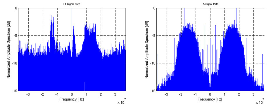
In the three configurations, we successfully acquired GPS L1 and Galileo E1 signals. We were also able to perform tracking on GPS L1 and L5I, as well as Galileo E1b and E5aI. Figure 8 shows the spectrum of a snapshot of L1 and L5 paths made using the on-chip dedicated snapshot hardware and sent through the UART port with a dedicated binary protocol for offline processing. For this special test, we used an arbitrary waveform generator to provide noiseless Galileo and GLONASS signals in the L1 and L5 frequency bands, supported by the NAPA chip. After performing a FFT of the two snapshots, we can clearly see these signals. In the L1 plot, the E1b signal is present in the negative frequency range with the two peaks typical of the BOC(1,1) modulation. The FDMA GLONASS G1 is in the positive frequency range with its trapezoidal characteristic. It is also possible to see a side lobe of the E1a BOCcos(15,2.5) in the proximity of the zero frequency. In the L5 plot, we can see the main peak of BPSK E5a signal on the right and its mirrored image on the left, due to the fact that L5 signal path is real.
Figure 8. Spectrum of L1 and L5 band showing a Galileo E1 and E5a signal.
Acknowledgment
This project has been funded by the Bundesministerium für Bildung und Forschung (BMBF) (German Federal Ministry of Education and Research), which is gratefully acknowledged.
Topcon Positioning Group’s technology and assistance will be used to create a large-scale landscape portrait planned for the National Mall.
Artist Jorge Rodríguez-Gerada has been commissioned by the Smithsonian’s National Portrait Gallery to create a six-acre portrait that will be a composite of several different faces. The project, titled “Out of Many, One,” will use high-precision GPS survey technology from Topcon to create the “facescape” between the World War II and Lincoln memorials along the south side of the Reflecting Pool. The portrait will be viewable from atop the Washington Monument.
The facescape will be built along the Reflecting Pool on the National Mall.
Topcon is providing equipment and personnel to help create the portrait. “Topcon GPS technology is my paintbrush,” Rodríguez-Gerada said. “This facescape would not be possible without the highly precise GPS and hybrid positioning equipment, as well as the technological expertise contributed by Topcon.”
“In a sense it is reverse surveying,” said Mark Contino, Topcon vice president of global marketing. “Surveyors normally measure the real world and scale it down to readable maps. In this case, the project starts in the artist’s mind and each contour of his drawing will be redrawn in the field using stakes guided by Topcon GPS technology and MAGNET Field software.”
The GPS positioning portion of the project will begin the week of September 15, and the final portrait is expected to be completed for unveiling in October.
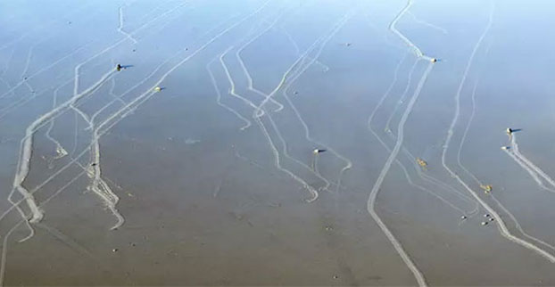
Rarely formed sheets of ice push rocks across a dry lake in Death Valley.
In Racetrack Playa in Death Valley, California, hundreds of rocks — some weighing as much as 700 pounds — seem to have been dragged across the ground, leaving synchronized trails that can stretch for hundreds of meters. Though many phenomena were speculated (hurricane-force winds, dust devils, slick algal films, thick sheets of ice), no one knew what caused the movement.
To solve the mystery, in 2011 a team of researchers led by paleobiologist Richard Norris, Scripps Institution of Oceanography, UC San Diego, began monitoring the rocks remotely. The research team fit 15 similar rocks with custom-built, motion-activated GPS units (the National Park Service disallowed use of native rocks) and installed a high-resolution weather station capable of measuring gusts to one-second intervals. Then — in what Ralph Lorenz of the Applied Physics Laboratory at the Johns Hopkins University suspected would be “the most boring experiment ever” — the researchers waited for something to happen.
In December 2013, Richard Norris and co-author and cousin Jim Norris discovered that the playa was covered with a pond of water three inches deep. Shortly after, the rocks began moving.
“Science sometimes has an element of luck,” Richard Norris said. “We expected to wait five or ten years without anything moving, but only two years into the project, we just happened to be there at the right time to see it happen in person.”
Their observations show that moving the rocks requires a rare combination of events. First, the playa fills with water, which must be deep enough to form floating ice during cold winter nights but shallow enough to expose the rocks. As nighttime temperatures plummet, the pond freezes to form thin sheets of “windowpane” ice, which must be thin enough to move freely but thick enough to maintain strength. On sunny days, the ice begins to melt and break up into large floating panels, which light winds drive across the playa, pushing rocks in front of them and leaving trails in the soft mud below the surface.
“On December 21, 2013, ice breakup happened just around noon, with popping and cracking sounds coming from all over the frozen pond surface,” said Richard Norris. “I said to Jim, ‘This is it!’”
The rocks moved under light winds of about 3-5 meters per second (10 miles per hour) and were driven by ice less than 3-5 millimeters (0.25 inches) thick, a measure too thin to grip large rocks and lift them off the playa, which several papers had proposed as a mechanism to reduce friction. Further, the rocks moved only a few inches per second (2-6 meters per minute), a speed that is almost imperceptible at a distance and without stationary reference points.
“It’s possible that tourists have actually seen this happening without realizing it,” said Jim Norris. “It is really tough to gauge that a rock is in motion if all the rocks around it are also moving.”
Individual rocks remained in motion for anywhere from a few seconds to 16 minutes. In one event, the researchers observed rocks three football fields apart began moving simultaneously and traveled over 60 meters (200 feet) before stopping. Rocks often moved multiple times before reaching their final resting place. The researchers also observed rock-less trails formed by grounding ice panels — features that the Park Service had previously suspected were the result of tourists stealing rocks.
“The last suspected movement was in 2006, and so rocks may move only about one millionth of the time,” Lorenz said. “There is also evidence that the frequency of rock movement, which seems to require cold nights to form ice, may have declined since the 1970s due to climate change.”
The team’s findings were published in the journal PLOS ONE on August 27.
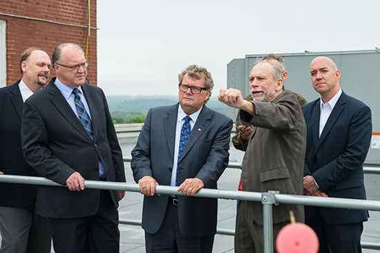
Professor Langley (fourth from left) discusses the UNB geodesy program with Canadian Science Minister Ed Holder (third from left.)
The Canadian Minister of State for science and technology, Ed Holder, visited the University of New Brunswick on July 28 to announce the awarding by the Natural Sciences and Engineering Council of $2.4 million to 28 UNB researchers.
He was joined by Keith Ashfield, member of Parliament for Fredericton, where UNB is based, and Craig Leonard, the New Brunswick Minister of Energy and Mines.
A highlight of the visit was a tour of the Department of Geodesy and Geomatics Engineering to see the work of Prof. Richard Langley and his students. Langley received $170,000 in Natural Sciences and Engineering Research Council (NSERC) funding in the competition. The funding will support the work of his group in improving augmented multi-constellation satellite-based precise positioning in a wide range of environments. Langley is GPS World’sInnovation editor, a post he has held since the magazine’s inception.
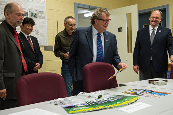
Canadian Science Minister Ed Holder looks at GPS World magazine, which has featured Innovation columns edited by Richard Langley for more than two decades.
Although GPS was the first widely available satellite navigation system, it has now been joined by the Russian GLONASS system, and will soon be accompanied by the European Galileo system, the Chinese BeiDou system, and the Japanese QZSS — all of which have test satellites now in orbit. There are interesting problems to be solved in gaining maximum benefits from this plethora of GNSS for precise positioning and navigation, and Langley and his team will address a number of them.
The team is also involved in the analysis of data from the GPS-based instrument on the Canadian CASSIOPE scientific satellite launched at the end of September 2013. The instrument, which precisely determines the position of the satellite and provides information on the state of the Earth’s ionosphere, was designed at UNB.
The NSERC Discovery Grants Program is an integral component of the government’s efforts to develop, attract and retain the world’s most talented researchers at Canadian universities. The program funds discovery research in a multitude of scientific and engineering disciplines, which builds a broad base of research capacity across the country.
Professor Langley gave the following presentation at the NSERC Discovery Grants Scholarships Rollout Announcement at UNB on July 28: