Hexagon AB has made the following organizational changes, effective immediately:
Paolo Guglielmini, currently president of the Hexagon’s Manufacturing Intelligence (MI) division, has been appointed chief operating officer (COO) for Hexagon AB.
In his new role, Guglielmini will support Hexagon President and CEO Ola Rollén to develop and implement Hexagon’s strategy, as well as overseeing the operations of the company’s divisions. Guglielmini will retain his current role as President for the MI division until a successor has been appointed.
Guglielmini has been leading MI since January 2020, and has served in key roles since joining Hexagon in 2010, from strategy and business development to M&A and general management. He has been instrumental in expanding MI’s focus towards software-centric quality data solutions, and with his team driving the business towards all-time-high performance in 2021.
Prior to joining Hexagon, Paolo held positions at CERN, the European Organization for Nuclear Research in Switzerland, and Accenture. He holds a Master of Science in Engineering and Master of Business Administration from IMD.
Norbert Hanke, currently Hexagon’s COO, has been appointed executive vice president (EVP) and will continue leading Hexagon Ventures, HR, IT, the India R&D and Sales organizations and other related tasks.
Both Guglielmini and Hanke will continue to report directly to Rollén and remain members of Hexagon’s executive management team.
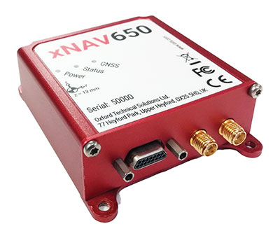
In 2021, OxTS released its smallest, lightest and most affordable inertial navigation system (INS) to date — the xNAV650.
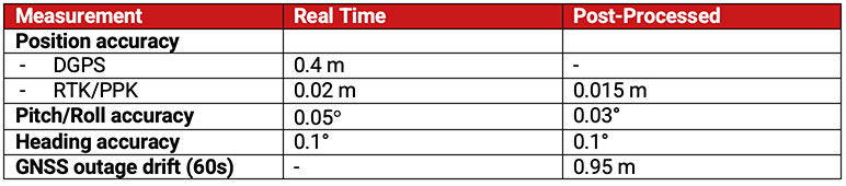
At release, the xNAV650 detailed real-time specifications only. However, after additional testing, OxTS has announced post-processed specifications.
Because of its small size and low weight, the xNAV650 is suitable for SWaP-constrained applications. It is also used in many mobile-mapping scenarios. Alongside OxTS Georeferencer, measurements created by the xNAV650 can be used to georeference point clouds from multiple lidar sensors.
By announcing these new specifications, OxTS aims to keep surveyors informed of the performance they can expect from the xNAV650 in both real time and post-processing.
OxTS has been manufacturing INS for more than 20 years. Their INS are widely used in both the automotive testing and survey and mapping industries.
Tallysman Wireless is introducing a north orientation mark to its TW3000 family of Accutenna precision antennas and its TW5000 family of smart antennas.
The new feature will allow customers to align their antennas, standardize radiation patterns, and increase the synchronicity of their azimuth gain readings across multiple devices.
The new north mark design has been thoroughly tested to ensure it conforms to or exceeds customer expectations and maintains each antenna’s stringent IP69K rating.
The new design will be introduced on Feb. 20 in all Tallysman TW3000 and TW5000 antennas’ radome options (flat and conical) and available colors (white, grey and black).
ComNav Technology has announced major upgrades to its T300 and T300 Plus GNSS receivers for the global market, including an upgrade to its GNSS K8 platform on both receivers and a tilt-sensor replacement for the inertial measurement unit (IMU) on the T300 Plus.
The upgraded T300 and T300 Plus provide reception of more GNSS channels and increased reliability, the company said.
More channels. The powerful full-constellation tracking ability on the K8 platform enables reception of all current and future GNSS signals, including GPS, BeiDou, GLONASS, Galileo, QZSS, NavIC and SBAS. Signal support and tracking for QZSS L1/L2/L5, Navic L5, Galileo E6 and Altboc as well as GLONASS L3 are also available. After the upgrade, T300 and T300 Plus each receive 965 GNSS channels, and offer robust GNSS tracking performance.
Improved reliability. The advanced GNSS real-time kinematic (RTK) technology on the K8 platform provides continuous centimeter-level positioning within a short period of time. To alleviate the influence on authentic satellite signals, the K8 platform enhances interference detection and mitigation. The interference, for example, between buildings or in the dense jungle, will not affect the positioning results.
With the upgrades, users can expand the reach of their GNSS rovers and obtain reliable positioning results even in complex environments.
Low power consumption. In static mode, power consumption is reduced to 1.92 W, extending working time to 16 hours and providing a smooth workflow without an external power supply.
T300 Plus tilt compensation. Combined with the inertial measurement unit (IMU), the T300 Plus can support tilt compensation up to 60° and keeps the accuracy within 2.5 centimeters, which significantly improves the fieldwork with increased efficiency, convenience and reliability without magnetometer and accelerometer calibration.
The upgraded T300 and T300 Plus GNSS receivers are available now.
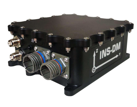
Inertial Labs has launched a new GNSS-aided inertial navigation system. INS-DM is an IP68-rated version of the company’s new generation of super ruggedized units, shielded from electromagnetic interference. The fully integrated device combines the inertial navigation system (INS) with an attitude and heading reference system (AHRS) and air data computer (ADC).
The high-performance strapdown system determines position, velocity and absolute orientation (heading, pitch and roll) for any device on which it is mounted. Horizontal and vertical position, velocity and orientation are determined with high accuracy for both motionless and dynamic applications.
The INS-DM can support multiple types of micro-electromechanical (MEMS) inertial measurement units (IMU) developed by Inertial Labs. The INS-DM also supports other IMUs like the Honeywell HG4930.
The INS-DM uses different multi-constellation (GPS, GLONASS, Galileo, BeiDou and QZSS) GNSS receivers such as the NovAtel OEM7 series or the u-blox F9 series.
The optional ADC is supported by two Honeywell barometric sensors and the ability to support an internal fluxgate or external stand-alone magnetic compass. The INS-DM contains Inertial Labs’ new onboard sensor-fusion filter, state-of-the-art navigation and guidance algorithms, and calibration software.
Key Features
Commercially exportable GNSS-aided INS
3-in-1 strapdown system: INS + AHRS + ADC
Embedded industrial, tactical or navigation-grade Honeywell or Inertial Labs MEMS IMU
Novatel OEM7 or u-blox ZED-F9P high-precision GNSS receiver
GPS, GLONASS, Galileo, BeiDou, QZSS and real-time kinematic signals supported
Total and static pressure sensors for calculating indicated airspeed
SBAS, DGPS, RTK and PPP corrections supported for precise real-time operation
GNSS measurements and IMU raw data for post processing
Advanced, extendable (based on application) embedded Kalman-filter-based sensor fusion algorithms
State-of-the-art algorithms for different dynamic motions of helicopters, UAVs, marine vessels and ground vehicles
Full temperature calibration of all sensing elements
EMC, EMI and ERD protection (MIL-STD-1275)
Environmentally sealed (IP68)
Aiding data: wind sensor, air-speed sensor, Doppler shift from locator (for long-term GPS-denied environments), external position and external heading.
The INS-DM is the result of more than 20 years of Inertial Labs’ experience developing and supplying INS solutions to land, marine and aerial platforms around the world.
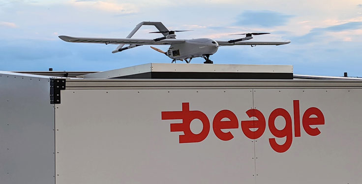
Hamburg-based start-up Beagle Systems has begun building a nationwide network of landing and charging stations for drones.
In Hanstedt (Lüneburger Heide) in the Lower Saxony region of Germany, the first hangar has been set up with an unmanned aerial system (UAS). From there, every surrounding place in Lower Saxony can be reached in a short time.
The drone will be deployed from the Beagle Systems headquarters in Hamburg. Beagle Systems has the corresponding permits for flights beyond visual line of sight (BVLOS).
“The start in Hanstedt is an important step for us,” said Oliver Lichtenstein, one of the three founders of Beagle Systems. “From here we can reach an area of 780,000 hectares in Lower Saxony. As the first provider of drone flights, we are thus on call within a short time at the customer’s site.”
The drone flight can be controlled entirely from Hamburg; on-site personnel deployment is not necessary. This eliminates personnel costs as well as time spent traveling to and from the site. Because of this, Beagle Systems can carry out drone flights at a much lower cost than other providers.
“Our goal is to build a nationwide network of charging stations within the next few years,” said Mitja Wittersheim, COO of Beagle Systems. “An EU-wide expansion is then the next step.” The expansion of the network would allow drone specialists to access a ready-to-go drone from Hamburg for customers at any location within the European Union.
Beagle Systems is a drone-as-a-service provider specializing in long-range flights with unmanned aerial systems. The drones are already in use for the inspection and monitoring of large infrastructure facilities such as power grids.
The company also plans to tap into the multi-billion dollar market of delivery, courier and express services. The Beagle M drone used in Hanstedt was developed in-house. It has a wingspan of 2.50 meters and can transport a load of up to three kilograms.
How Inertial Systems and GNSS Availability Will Help
Innovation Insights with Richard Langley
ARE WE THERE YET? This was a familiar refrain from the backseats of parents’ cars when traveling to a holiday destination or to grandparents when I was growing up. We didn’t have videos on a display attached to the seats in front of us or (who could imagine?) our own personal communication device on which we could call up games, movies or social media channels.
But I’m not talking about that complaint from our childhoods. I’m asking if we have arrived at the era of the self-driving car. The answer is yes and no. It all depends on what you mean by “self-driving.” We reviewed some of the technologies needed for self-driving or autonomous vehicles in this column in June 2019. And we indicated in the introduction to that column that vehicle autonomy has several levels. SAE International, formerly known as the Society of Automotive Engineers, has defined six levels of autonomy that can be briefly described as Level 0 – no automation; Level 1 – hands on/shared control; Level 2 – hands off; Level 3 – eyes off; Level 4 – mind off; and Level 5 – steering wheel optional.
Already, Level 1 automation is widely available in modern cars with adaptive cruise control, parking assistance, lane-keeping assistance and automatic emergency braking among the features being offered. Level 2 automation, where the automated system takes full control of the vehicle’s acceleration, braking and steering, is available in some production models, although the “hands-off” designation is not to be taken literally — most motor vehicle laws require drivers to keep their hands on the steering wheel. Between Level 2 and Level 3, we have conditional automation — the car can drive itself, but the driver must stay alert and be prepared to take over immediately. Level 3 is high automation, where a computer fully drives the car at certain times on certain routes such as a highway; while the driver can perform other tasks such as reading a book, they must be prepared to take over operation of the vehicle within a few seconds if alerted by the automated system. While test campaigns are still ongoing, some jurisdictions permit Level 3 operation by ordinary drivers on some roads, and customers will soon be able to buy vehicles with this level of automation. Widespread use of Level 4 and Level 5 automation is further off (some would say quite a way off) and remains in development. But famously, last year, Toyota operated Level 4 self-driving shuttle vehicles around the Tokyo 2020 Olympic Village.
A lot more work needs to be done before we will have arrived at the era of the fully self-driving car that will be able to travel on any road, anywhere in the world, all year around, in all weather conditions. In particular, self-driving cars in urban environments (as opposed to highway driving) can be problematic. The required multi-sensor automated systems will include GNSS, but buildings block and reflect GNSS signals, reducing system availability and accuracy. In “Innovation” this month, researchers from the Illinois Institute of Technology report on how inertial navigation systems coupled with wheel-speed sensors and vehicle dynamic constraints can help.
By Kana Nagai, Matthew Spenko, Ron Henderson and Boris Pervan
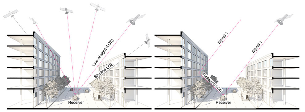
GNSS provides navigation services globally, but satellite visibility in urban areas is limited by high-rise buildings. This creates a mixture of GNSS available and denied environments (see FIGURE 1) — users do not generally know where the system can maintain sufficient levels of accuracy and integrity for a particular application. To begin to address the issue for self-driving cars, we evaluated GNSS-only availability in downtown Chicago.
FIGURE 1 . The figure depicts three types of potential GNSS signal reception: direct LOS signals and blocked LOS signals (left) and reflected LOS signals (right). (Image: Authors)
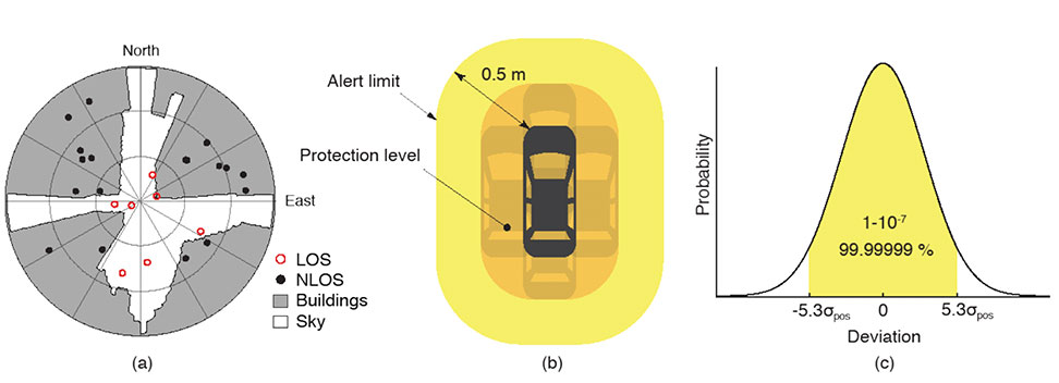
GNSS signal prediction in urban environments has been conducted in previous work. For example, the concept of “shadow matching” was developed to identify GNSS signal blockages in urban canyons. Overlaying sky plots on a hemispherical sky view can be used to distinguish between line-of-sight (LOS) and non-line-of-sight (NLOS) signals (see FIGURE 2a). Reflected rays can be predicted using Householder transformations to reveal potential multipath conditions. Satellites producing blocked or reflected (NLOS) signals should be excluded to maintain integrity.
FIGURE 2. (a) A hemispherical sky view in an urban environment. (b) Illustration of a protection level and an alert limit. To ensure integrity, the protection level must not exceed an alert limit. (c) The allowable probability of exceedance is assumed to be 10−7 in this work. (Image: Authors)
When the number of visible satellites is greater than three, GNSS can resolve vehicle position. However, even in cases where enough satellites are visible, the satellite geometries are generally weak because the dilution of precision (DOP) is adversely affected by the buildings partially blocking the sky. Horizontal positioning error must be bounded by a protection level computed by the vehicle. Then, for navigation to be deemed available, the protection level must not exceed a required alert limit (see FIGURE 2b). The maximum allowed probability of exceedance (see FIGURE 2c) and the alert limit can together be used to determine the maximum allowable position error standard deviation.
Even if the protection level is far below the alert limit in an open-sky environment, it will frequently exceed the alert limit once the vehicle enters a city. GNSS alone is generally not able to maintain availability, so integration with other sensors is needed. Tightly coupling inertial navigation systems (INS) with GNSS using the extended Kalman filter (EKF) provides better estimation in urban environments. The EKF algorithm also enables integration of wheel-speed sensors and vehicle dynamic constraints. These integrated navigation systems will improve availability, but it is still unclear how long such a system can be expected to maintain fault-free integrity in a congested city.
Focusing on the problem of self-driving cars in urban environments, we evaluate protection levels of navigation with practical integrated sensors: GNSS, INS, a wheel-speed sensor (WSS) and vehicle dynamic constraints (VDC). The goal is to develop the means by which we can determine locations where external ranging sources (such as lidar) are needed to maintain continuous navigation with fault-free integrity.
GNSS-ONLY AVAILABILITY
For GNSS availability evaluation, we assume an integrity requirement that the probability of exceeding a 0.5-meter alert limit must be lower than 10−7. The 0.5-meter alert limit therefore corresponds to approximately five times the position standard deviation, so the maximum allowable position error standard deviation is then approximately 0.1 meters. Accuracy at this level clearly requires differential GNSS carrier-phase measurements. We assume a nominal GNSS double difference (DD) carrier ranging error standard deviation of approximately 0.02 meters, and that carrier cycle ambiguities can be readily resolved in an open-sky environment prior to initiation of vehicle motion.
Given the assumptions made of the maximum allowable position error standard deviation and the GNSS ranging error standard deviation, the maximum allowable horizontal dilution of precision (HDOP) is about 5.
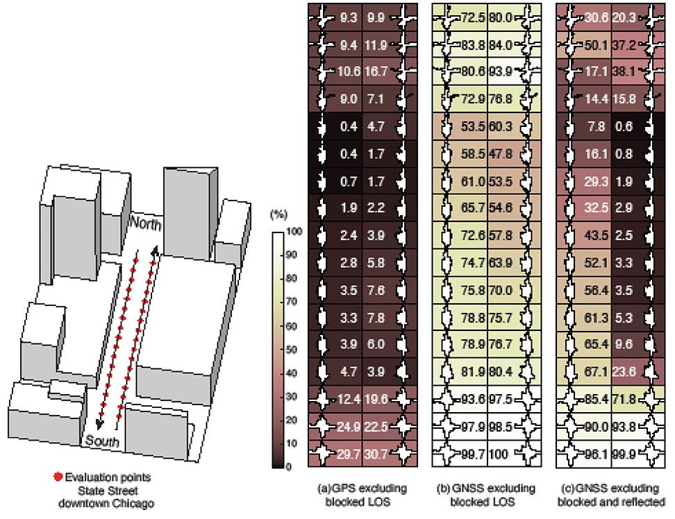
FIGURE 3 shows GPS and GNSS availability — the fraction of time the HDOP requirement is met over 24 hours — along a section of State Street in downtown Chicago. The availability results using GPS only and excluding only blocked LOS signals ranged from 0% to 9% along the block and 9% to 30% at the intersections (see FIGURE 3a). Using four full GNSS constellations (GPS, Galileo, GLONASS and BeiDou), availability ranged from 48% to 82% along the block and 72% to 100% at the intersections (see FIGURE 3b).
FIGURE 3. The percentage of GPS or GNSS availability in 3D-mapped downtown Chicago. We exclude satellites producing blocked LOS signals or both blocked and reflected LOS (NLOS) signals from the measurements. Each column expresses a lane of southbound or northbound travel. The availability is the percentage of total time when HDOP meets the self-driving car integrity requirements in 24 hours. (Image: Authors)
When we also excluded satellites producing reflected LOS signals that reach the vehicle, the availability dropped significantly at every point (see FIGURE 3c). We assert that FIGURE 3c expresses the reality of GNSS availability because building-reflected multipath signals degrade positioning accuracy and would affect integrity negatively. It’s obvious from these results that GNSS alone is insufficient to meet the autonomous driving requirements in an urban environment, and multi-sensor integrated navigation systems are needed to augment poor GNSS signal availability.
MULTI-SENSOR INTEGRATION
We begin by considering tightly coupled INS/GNSS integration using an EKF, and then integrate a realistic sensor suite including WSS and vehicle dynamic constraints that enforce resistance to lateral sliding and vertical movement. If it is known from another source that the vehicle is not moving (for example, it is in the parking gear), a static mode constraint (SMC) can also be applied.
INS/GNSS Integration. Tightly coupled INS/GNSS integration with an EKF uses the INS measurement to predict vehicle motion. The continuous process model uses a state vector having the position in the navigation frame, the velocity, the attitude, bias errors and cycle ambiguities, with the input vector having accelerometer-specific force measurement in the body frame and gyro-rotation-rate measurements. A white-noise vector drives the inertial measurement unit (IMU) states.
The GPS/GNSS measurement model includes the measurement vector having carrier and code phases, and the observation matrix containing LOS vectors and the vector of white receiver thermal noise.
INS/GNSS/WSS/VDC Integration. For the vehicle in motion, we developed a model consisting of a WSS measurement in the along-track direction, a non-holonomic constraint resisting lateral sliding, and a holonomic constraint on vertical movement (see FIGURE 4).
The INS/GNSS/WSS/VDC integration using the EKF consists of the process model and the measurement models.
INS/GNSS/SMC Integration. The static mode constraint provides zero-velocity measurements to the EKF measurement update to mitigate position error propagation. We use SMC only when it is known that the vehicle is not moving; for example, when the vehicle is in the parking gear.
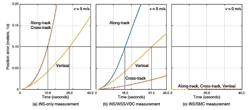
Error Propagation Analysis. We tested the time from perfect initialization to when position error exceeds 0.1 meters in GNSS-denied environments. FIGURE 5 shows the error growth in the along-track (x), the cross-track (y) and the vertical (z). The error specifications for a STIM300 tactical-grade IMU are used in this analysis. The standard deviation of the WSS measurement noise is assumed to be 0.05 meters per second, and the standard deviation of the movement constraint violations is 0.001 meters per second. The vehicle is moving at 5 meters per second except when we test the SMC.
FIGURE 5. The vehicle position error growth vs. time in the along-track (x), cross-track (y) and vertical (z) directions. Each graph represents the navigation system introduced in the multi-sensor integration section. The vehicle is moving at 5 meters per second (a and b) or 0 meters per second (c). (Image: Authors)
The INS can coast 15.6 seconds before the position error standard deviation exceeds 0.1 meters in both the along-track and the cross-track directions (see FIGURE 5a). The INS/WSS/VDC can coast 16.5 seconds in the along-track direction, and significantly more than 40 seconds (the simulation duration) in the cross-track direction (see FIGURE 5b). In static mode, INS/SMC estimate errors do not grow with time in any direction, as expected (see FIGURE 5c). In GNSS-denied environments, the non-holonomic constraint suppresses the cross-track position error, but the WSS measurement hardly affects the along-track position error. The SMC works perfectly, but the usage is limited to when the vehicle is known to be stationary.
SIMULATION SCENARIO
We imagine a future driverless-car mission scenario in which multi-sensor navigation systems are practicable. To minimize congestion in a city, autonomous vehicles will be held outside the urban core when not in use. In the clear open-sky environment, a vehicle in a parking lot completes GNSS initialization using the INS/GNSS/SMC system. Once requested for action, the vehicle departs for the city from the parking lot, and the motion of the vehicle improves alignment by the INS/GNSS system. Safe navigation can be ensured using the system to provide continuity under overpasses and bridges in the open-sky environment. Upon entering the urban core, navigation becomes more dependent on the INS/WSS/VDC system.
A reasonable numerical target for differential GNSS initialized position error is 0.02 meters, and for the INS alignment yaw angle error 0.1 degrees.
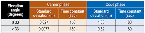
Local GNSS multipath errors from nearby vehicles will vary with the satellite elevation angle. Prior experimental results show that lower elevation-angle satellite signals (below 33 degrees) are much more likely to be impacted by multipath than higher ones (see TABLE 1).
TABLE 1. The nominal GNSS multipath error values in the simulation.
INITIALIZATION AND ALIGNMENT
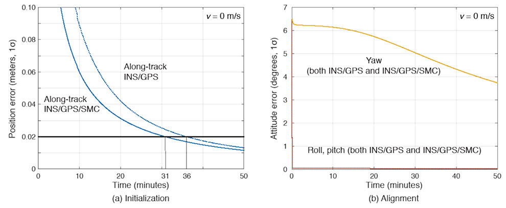
Initialization takes place in a parking lot with a clear sky view. A vehicle is in the parking gear, enabling SMC to be applied. FIGURE 6a shows a typical example: with INS/GPS/SMC, system initialization takes about 31 minutes, and with INS/GPS, about 36 minutes. Therefore, SMC does speed up GPS initialization, although the improvement is modest.
The yaw angle is not aligned during the initialization, but roll and pitch are immediately aligned (see FIGURE 6b). Earth’s gravity affects roll and pitch angle alignment but not yaw angle.
FIGURE 6. (a) Comparisons of initialization time between INS/GPS and INS/GPS/SMC in an open-sky environment. The INS/GPS/SMC system initializes rapidly. (b) Transitions of roll, pitch, yaw alignment during the initialization. Yaw angle alignment cannot be performed when the vehicle is stationary. (Image: Authors)
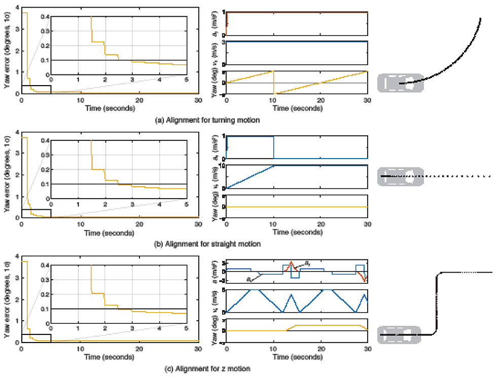
Yaw angle alignment cannot be performed when the vehicle is stationary or moving with constant velocity. Accelerated motion, either straight or turning, is required. FIGURE 7 shows the behavior of the yaw angle error standard deviation using the INS/GPS system when centripetal (see FIGURE 7a) or tangential (see FIGURE 7b) acceleration is applied. The yaw angle can be aligned in a couple of seconds for either type of acceleration. To represent typical initial motions of self-driving cars, we model a parking-lot departure via a “Z”-shaped path. In this scenario, the yaw alignment error reaches 0.1 degrees within a couple of seconds (see FIGURE 7c).
FIGURE 7. The behavior of yaw angle error when centripetal (a) or tangential (b) acceleration is applied; (c) shows the behavior while following a z-shaped path. The yaw angle can be aligned in a couple of seconds in each case. (Image: Author)
EVALUATION IN URBAN ENVIRONMENTS
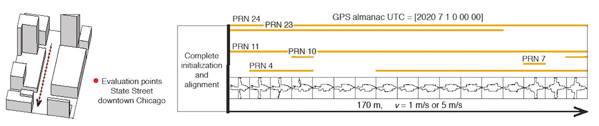
After initialization and alignment in the open-sky environment, we simulated the vehicle traveling into the urban core. The urban environment in our study is 3D-mapped State Street in Chicago, which runs north-south and transits from low-rise neighborhoods to central downtown. We selected one congested section surrounded by tall buildings and computed the position error standard deviation along the path. The evaluation points are at 10-meter intervals over a total distance of 170 meters. The yellow lines in FIGURE 8 denote the visible satellites, identified by their pseudorandom noise (PRN) code numbers, at each point. We assume for convenience that the INS/GPS system is initialized and aligned at the first evaluation point. In reality, we would expect a degraded initial condition because we are starting the simulation in an urban canyon.
FIGURE 8. Evaluation points and PRN numbers of visible satellites at each point. (Image: Author)
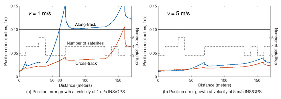
In the first simulation, the car equipped with the INS/GPS system moved either 1 or 5 meters per second. The y-axis in FIGURE 9 represents the position error standard deviation, and the x-axis represents the distance in meters. The dotted line expresses the number of visible satellites. The error when the vehicle velocity is 1 meter per second exceeded the maximum allowable position error standard deviation of 0.1 meter, at the distance of 60 meters. However, when the velocity was 5 meters per second, the maximum allowable position error standard deviation was never reached. It is also clear from the figures that error propagation is significantly affected by the number of visible satellites.
FIGURE 9. A comparison of position error growth between velocities of 1 meter per second and 5 meters per second. (Image: Author)
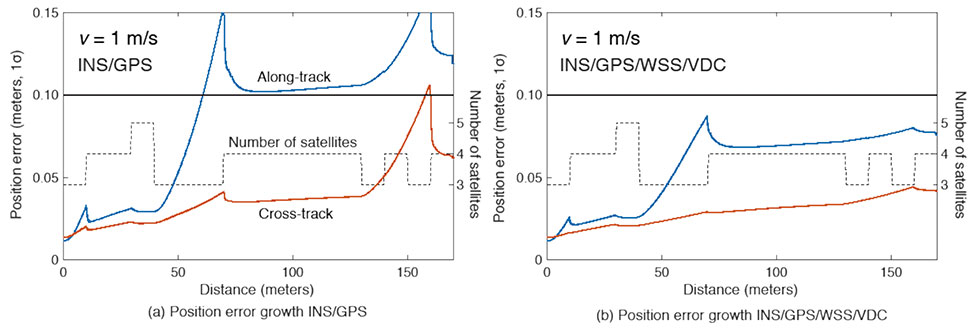
In the second simulation, we compared two different navigation systems, INS/GPS and INS/GPS/WSS/VDC. The vehicle moved at 1 meter per second in the same urban environment. The INS/GPS/WSS/VDC system does provide relief, but the error propagation is still clearly affected by the number of visible satellites (see FIGURE 10).
FIGURE 10. A comparison of position error growth between the INS/GPS and INS/GPS/WSS/VDC systems for a velocity of 1 meter per second. (Image: Authors)
In GNSS-challenged environments, INS error propagation is a function of time. When a vehicle moves faster, it clears the blockage area more quickly, reducing the impact of INS drift — a function of time, not distance. In contrast, GNSS error is completely determined by location. Because INS error propagation depends on how long the vehicle stays in an area of GNSS outage, protection levels for trips through the same area will be different if the vehicle is smoothly cruising or gets stuck in a traffic jam.
CONCLUSION
To gain a better understanding of how long and under what local conditions multi-sensor integrated navigation systems can maintain fault-free integrity, we evaluated navigation positioning errors in 3D-mapped downtown Chicago. The system we developed consists of sensors with which self-driving cars would reasonably be equipped: GNSS, INS, WSS and dynamic constraints. We showed that INS/GPS position errors along the path depend very strongly on the vehicle’s speed. When the system is augmented with WSS/VDC, position errors are suppressed, but the error propagation is still strongly influenced by the number of visible satellites.
ACKNOWLEDGMENTS
The research described in this article is supported by the National Science Foundation. Figure 1 was created by Alexis Arias of the Landscape Architecture + Urbanism Program at the Illinois Institute of Technology (IIT). The authors greatly appreciate the advice and help of Nilay Mistry from that program.
This article is based on the paper “Evaluating INS/GNSS Availability for Self-Driving Cars in Urban Environments” presented at ION ITM 2021, the virtual 2021 International Technical Meeting of The Institute of Navigation, Jan. 25–28, 2021.
KANA NAGAI is a Ph.D. candidate and research assistant in mechanical and aerospace engineering at IIT.
MATTHEW SPENKO is a professor of mechanical and aerospace engineering at IIT. He earned his M.S. and Ph.D. degrees in mechanical engineering from the Massachusetts Institute of Technology.
RON HENDERSON is a professor and director of the Landscape Architecture + Urbanism Program at IIT. He earned his Master of Landscape Architecture and Master of Architecture from the University of Pennsylvania.
BORIS PERVAN is a professor of mechanical and aerospace engineering at IIT. He earned his M.S. from the California Institute of Technology and Ph.D. from Stanford University.
Register today to attend the ION’s co-located International Technical Meeting (ITM) and the Precise Time and Time Interval (PTTI) Systems and Applications Meeting, being held January 25–27, 2022, at the Hyatt Regency Long Beach in Long Beach, California, with technical presentations available for on-demand viewing at ion.org.
Plenary and Keynote Sessions
The ITM/PTTI 2022 keynote addresses, “Traffic Jams, Autonomy, and Lagrangian Control” and “The Future of Industrial Atomic Clocks,” taking place on Tuesday, January 25 will be recorded live and uploaded for on-demand viewing through the ITM/PTTI 2022 virtual meeting portal.
Technical Sessions
Individual technical presentations will be pre-recorded and uploaded with slides to the ITM/PTTI 2022 virtual meeting portal for viewing at a time of your choosing, and will remain available for 30 days. Attendees will have the option to submit questions to each presenter. View the full online Technical Program now!
Exhibit Experience
ITM/PTTI 2022 features industry partners with expanded exhibitor profiles, that allow attendees to review the latest PNT-related technologies, products, and product demonstration videos.
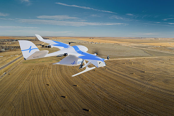
German drone-delivery company Wingcopter has signed a commercial agreement with Spright worth US$16 million to enable UAV medical deliveries.
Spright is a subsidiary of American air medical service provider Air Methods. Under the agreement, Spright is acquiring a fleet of Wingcopter’s flagship delivery drone, the Wingcopter 198, to meet the increasing demand for medical drone deliveries throughout the United States.
The contract makes Wingcopter the exclusive provider of fixed-wing electric vertical take-off and landing (eVTOL) delivery-drone technology to Spright. Spright, in turn, becomes exclusive provider of maintenance, repair and overhaul for the Wingcopter 198 to third parties in the United States.
Drone Division Launched
Spright was launched in July 2020 as the new drone division of Air Methods to improve healthcare access and minimize supply challenges for customers across the United States. To this end, Spright is creating a drone-based, U.S. healthcare-specific delivery network leveraging an existing infrastructure of more than 300 bases, serving hundreds of hospitals across 48 states in predominantly rural areas.
The agreement further strengthens the strategic partnership between the two companies, announced in August 2021. Spright is closely supporting Wingcopter in its Federal Aviation Administration (FAA) UAS type-certification process, leveraging Spright’s aviation experience operating FAA 121 and 135 air carriers, its existing Part 135 certificate (on-demand air service) and safety management system program.
Spright is collaborating with Hutchinson Regional Health System in Hutchinson, Kansas, for initial tests, and plans to expand the service beyond Kansas with additional strategic medical projects later this year.
The Wingcopter fleet will increase healthcare access across rural and underserved communities by enabling instant and on-demand delivery of vital medical supplies, medications, vaccines, blood and lab samples between medical facilities. It will also improve quality of care for patients with faster turn-around time of lab samples and more targeted treatments for patients.
Finally, the electrically powered Wingcopter cargo drones will reduce the medical industry’s carbon footprint, contributing to greener and more sustainable supply chains with faster and more predictable delivery times.
Wingcopter and Spright will showcase the Wingcopter 198 delivery drone and provide an opportunity to meet executives of both companies at the logistics tech conference Manifest in Las Vegas Jan. 25-27.
Case New Holland (CNH) has selected the Tallysman Wireless VeraChoke antenna for modernization of its high-precision European GNSS real-time kinematic (RTK) network.
“The objective of the GNSS antenna update is to enable the tracking of all GNSS constellations and signals, thus improving the robustness, convergence time, and accuracy of positioning within CNH’s European RTK network,” said Michiel Jochims, CNH Industrial RTK manager EMEA. “At this stage, with only 25 stations updated, we are delighted to observe a significant performance improvement. We look forward to continuing the network update and bringing enhanced positioning to all of our European customers.”
The VeraChoke antenna provides excellent multipath suppression and repeatability of PCV and group delay variation (GDV), making it suitable for GNSS reference networks, explained Temo Wubbena, CEO of Geo++. “After detailed analysis, we have recommended Tallysman’s VeraChoke antenna to CNH Industrial.” Geo++ is supporting the upgrade of CNH Industrial’s European RTK network.
The patented VeraChoke has a very tight phase center variation (PCV), strong multipath mitigation and excellent performance across the full GNSS spectrum. Its PCV and phase center offsets (PCOs) are repeatable from unit to unit, making suitable for network RTK applications.
Hemisphere GNSS has announced another Vega heading and positioning OEM board using the Lyra II and Aquila chipsets.
The Vega 60 GNSS board fits industry-standard 46 x 71 mm form factors with a 60-pin connector. It can be used to replace more expensive and lesser abled 60-pin boards with either single- or dual-antenna capabilities.
Hemisphere’s Lyra II and Aquila application-specific integrated circuit (ASIC) designs provide the ability to simultaneously track and process more than 1,100 channels from all GNSS constellations and signals including GPS, GLONASS, Galileo, BeiDou, QZSS, NavIC, SBAS and L-band. The ASIC technology offers Vega 60 scalable access to every modern GNSS signal available.
Cygnus interference mitigation technology is also a standard feature, providing built-in digital filtering capabilities and spectrum analysis. This provides enhanced anti-jamming as well as interference detection and mitigation.
“We are excited for the opportunity to introduce our Vega 60 board,” said Miles Ware, director of marketing at Hemisphere. “Vega 60 brings our industry-leading heading and position solutions to an OEM board footprint with very few affordable upgrade paths.”
“Seen & Heard” is a monthly feature of GPS World magazine, traveling the world to capture interesting and unusual news stories involving the GNSS/PNT industry.
Photo: lindsay_imagery/E+/Getty Images
Where Sea Turtles Nest
Florida’s Sea Turtle Grants Program — funded with proceeds from special license-plate sales — were used to purchase Trimble TDC100 and TDC600 handheld GNSS receivers for state park staff to gather data about turtle nesting activity. The staff also uses Esri’s ArcGIS Survey123 field-capture software to report on turtles using the 108 miles of beach in 40 of Florida’s state parks. Negative impacts from commercial fishing, plastic waste and climate change have become a threat to sea turtles, which are now classified as an endangered species.
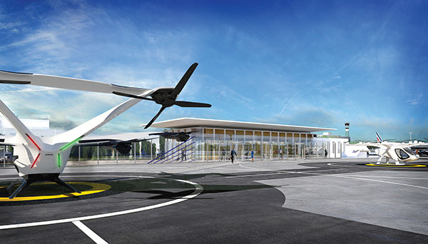
Concept of vertiport at airport. (Groupe ADP)
Paris up in the Air
Paris has begun testing electric air taxis at a new site outside the French capital, with an eye toward creating at least two demonstration flight paths during the 2024 Olympics to ferry passengers from nearby airports. Inaugurated in November, the test site is dedicated to new sustainable urban air mobility, and will study the use of electric vertical take-off and landing (eVTOL) aircraft. Choose Paris Region, Groupe ADP and RATP Group are managing the effort with VoloCity taxis by Volocopter onboard.
Photo: Stanislav Ostranitsa/iStock/Getty Images Plus/Getty Images
Russia Threatens GPS
The Kremlin warned it could blow up 32 GPS satellites with its new anti-satellite technology (ASAT), which it tested Nov. 15 on a retired Soviet Tselina-D satellite, according to numerous news reports. Russia then claimed on state television that its new ASAT missiles could obliterate NATO satellites and “blind all their missiles, planes and ships, not to mention the ground forces,” said Russian Channel One TV host Dmitry Kiselyov, rendering the West’s GPS-guided missiles useless. “It means that if NATO crosses our red line, it risks losing all 32 of its GPS satellites at once.”
Bali toll gate. (Photo: dwart/iStock/Getty Images Plus/Getty Images)
Indonesia Goes Cashless
Indonesia’s GNSS-based cashless toll system will take effect by the end of 2022, reports Indonesia Expat. The country’s Public Works and Public Housing Ministry plans to have its multi-lane, free-flow-based non-cash toll transaction system implemented on 40 toll roads on the islands of Java and Bali. MLFF uses GNSS plus a map-matching process and special toll road apps on smartphones to determine fees. The system is expected to increase efficiency, effectiveness, security and convenience in conducting toll road payment transactions.