Category: Uncategorized

  • GNSS receivers track port movements with CORS corrections

    GNSS receivers track port movements with CORS corrections

    The largest seaportS on America’s West Coast are the Ports of Long Beach and Los Angeles, located next to each other in San Pedro, California. (Photo: Art Wager/E+/Getty Images)
    The largest seaportS on America’s West Coast are the Ports of Long Beach and Los Angeles, located next to each other in San Pedro, California. (Photo: Art Wager/E+/Getty Images)

    The Port of Long Beach, California, is moving up and down because it sits on fault blocks that move like pistons due to subsidence caused by oil extraction. To accurately keep track of these movements, the port’s surveyors use GNSS receivers that receive corrections from continuously operating reference stations (CORS) operated by the port and by the City of Long Beach.

    CORS corrections compensate for errors inherent in GPS — clock drift, orbit errors, signal errors and atmospheric errors.

    Monitoring Subsidence. A monitoring receiver is placed on each fault block’s anticline, said Kim Holtz, director of survey for the Port of Long Beach. Her agency has 15 stations, along the coast, and a couple in the Port of Los Angeles. They were installed originally in the 1990s, using Trimble 5700s. “We are constantly monitoring to make sure that the fault blocks are not moving too much and that they are not moving horizontally other than all together, as the plates move to the north,” Holtz said.

    Also, the Long Beach Energy Resources Department has 14 Trimble R9 base stations. While Energy Resources uses the equipment to get precise elevation differences and measure subsidence for movement of more than 0.025 feet, the port uses them mainly for horizontal measurements for construction.

    The port’s hydrographic survey boat, the pilot boats, and the dig alert crew that marks utilities for construction operations also use the receivers to tie into the CORS network. “The stations are about eight or nine years old and Energy Resources is getting ready to replace all of them with Trimble Alloy GNSS reference receivers, over a three-year period,” Holtz said.

    Digital Level Run. The port normally performs a digital level run from a tidal wave base station in San Pedro, which dates to the 1920s. “We run a level run from that and, at the same time, Energy Resources does a GPS subsidence survey, where they get elevation,” Holtz explained. “Last year, we combined the two surveys, to compare the data and see whether we could use some of their GPS data for our level run. It was very promising. We are going to do it again in November.

    “Then, if it works, we will cut our level run, which normally takes two months, down to about a week or two. We will just come off of the main benchmarks on which Energy Resources puts a GPS elevation.”

    To keep the elevations tight, more than 10 years ago Long Beach created its own geoid. “It is a hybrid of GEOID12B, and we’ve updated it a couple of times,” Holtz said.

  • Quantum Reversal adds new GNSS anti-jam units to product offerings

    Quantum Reversal adds new GNSS anti-jam units to product offerings

    The QR100 and QR201 anti-jamming devices. (Photo: Quantum Reversal)
    The QR100 and QR201 anti-jamming devices. (Photo: Quantum Reversal)

    Quantum Reversal has added several new models to its flagship anti-jamming line. The company introduced in February the QR100 L1/L2 GPS anti-jamming unit and the QR101 L1/L2 GPS anti-jamming antenna.

    The current solution consists now of five products designed for the commercial market to solve the issue of unintentional RF interference or jamming:

    • QR100 – GPS dual frequency L1/L2 anti-jamming unit
    • QR200 – GPS dual frequency L1/L2 anti-jamming antenna
    • QR101 – GNSS multi frequency bands anti-jamming unit
    • QR201 – GNSS multi frequency bands anti-jamming antenna
    • QR202 – GNSS multi frequency band anti-jamming antenna with additional L-band reception
      (1520-1560 MHz)

    All models provide robust GPS or GNSS navigation solution, blocking intentional jamming and unintentional RF interference for services such as timing or 3D positioning.

    All the products are lightweight (230 grams for QR1xx series and 500 grams for QR2xx series) with low power consumption (1-1.5 Watt typically, depending on the configuration), and can be mounted on any platform (cars, poles, drones, etc.).

    Quantum Reversal operates in the information and wireless technology sector, developing innovative wireless and antenna technologies for various commercial markets. The QR team has experience designing products for applications in space, underwater, robotics and unmanned aerial vehicles (UAVs) for the commercial and user end. Each application requires a specific solution to deal with specific environmental (pressure, temperature, vibration, etc.) and operational conditions.

    The company sells stand alone products as well as OEM products that can be integrated within the customer products.

  • Guiding an unmanned vessel

    Guiding an unmanned vessel

    U.K.-based Unmanned Survey Solutions (USS) has created a unique unmanned surface vessel called the Accession Class USV. It’s modular design offers three variable boat lengths depending on the desired application. The base boat length of 3.5 m can be extended to 4.25 m or 5 m by adding additional hull sections.

    The standard USV configuration includes sensors for meeting International Hydrographic Organization (IHO) special-order surveys. The sensors consist of an R2Sonic SONIC 2024 multibeam sonar; an SBG Apogee Navsight Inertial + GNSS solution, and a Valeport MiniSVS and Swift SVP for measuring sound velocity.

    Image: Unmanned Survey Solutions
    Image: Unmanned Survey Solutions

    The data is acquired in either Hypack or QINSy hydrographic software and used for mission planning, data acquisition, post processing and final products. Designed for operations in both nearshore and offshore environments, the autonomous platform is safer and more cost-effective than comparative manned vessels, USS said.

    Image: Unmanned Survey Solutions
    Image: Unmanned Survey Solutions

    Although the Accession USV is payload agnostic and fully customer configurable, the standard configuration can also be interfaced with a mobile lidar such as the Carlson Merlin laser scanner for mapping terrestrial structures to create a full 3D point cloud above and below the water. This is achievable because of the embedded SBG inertial navigation system (INS), which is extremely versatile for both shallow or deeper water regions as well as challenging GNSS environments such as under bridges. In such situations, the centimeter-level RTK position accuracy is greatly improved using the SBG’s Qinertia post-processing software. This PPP- and PPK-capable software offers single or virtual base-station modes and can even incorporate users’ own base-station RINEX data.

    “Not only did we want to create an autonomous vessel specifically for surveyors, but we also wanted to incorporate the latest advanced sensor technologies,” said James Williams, USS director. “It was also extremely important that the final combined solution had a low CO2 footprint and was more cost effective than similar manned vessels.”

  • New Taoglas antennas aimed at robotics, autonomous vehicles

    New Taoglas antennas aimed at robotics, autonomous vehicles

    Taoglas has unveiled active, multiband GNSS antennas engineered for applications that require critical high-accuracy positioning and timing, including autonomous driving and precision agriculture. Both the MagmaX2 AA.200 and Colosseum X XAHP.50 add to Taoglas’ high-precision GNSS range.

    “Safety standards for autonomous vehicles (UAVs, robotics and vehicles) and precision agriculture is an ever evolving arena,” said Ronan Quinlan, co-CEO and founder of Taoglas. “However, it’s increasingly apparent that high-precision positional accuracy is critical for both. At Taoglas we’re continuously innovating our GNSS antennas to deliver the very best precise location capabilities, but in more lightweight, compact structures, compared to larger counterparts already on the market. We look at the impact the antenna has on the actual positioning performance of your system, not just the antenna itself.”

    The MagmaX2 AA.200. (Photo: Taoglas)
    The MagmaX2 AA.200. (Photo: Taoglas)

    The MagmaX2 AA.200 is designed for space and weight constrained applications, such as robotic lawnmowers, Quinlan said. Embedded antenna versions are also available.

    The AA.200 is a low-profile active multiband GNSS magnetic mount antenna for use across most major constellations including GPS (L1/L2/L5), GLONASS (G1/G2/G5), Galileo(E1/E5a/E5b) and BeiDou(B1/B2). It exhibits excellent gain and good radiation pattern stability leading to a reliable GPS fix in areas of weaker signal strength.

    Positional accuracy better than 60 cm (DRMS) is achievable, even without RTK corrections services. Accurate positioning down to 1.4 cm has been demonstrated with today’s multiband GNSS receivers and RTK services in the field.

    The Colosseum X XAHP.50 antenna. (Photo: Taoglas)
    The Colosseum X XAHP.50 antenna. (Photo: Taoglas)

    The Colosseum X XAHP.50 is a geodetic-quality small-dome antenna suitable for a vehicle roof mount or pole mount. “Every element and aspect of the antenna performance has been optimized during the design of this antenna,” Quinlan said. “This includes many deep interlocking rf parameters for true accurate centimeter-level positioning, compared to legacy meter-only level systems. Phase center variation, group delay, multipath rejection, axial ratio over angle all become critical considerations and performance targets.”

    The XAHP.50 is engineered to operate with incredibly high precision capabilities on the full GNSS spectrum. Sub meter positional accuracy better than 55cm (DRMS) is achievable, even without the use of RTK correctional services. This allows the user to achieve higher location accuracy, as well as stability of position tracking in urban environments.

    The XAHP.50 has excellent performance across the full bandwidth of the antenna and its design has an even gain across the hemisphere giving excellent, broad axial ratio which in turn makes it resilient to multipath rejection and excellent phase centre stability. Accurate positioning down to 1.4 cm has been demonstrated with today’s multiband GNSS receivers and RTK services in the field.

    Antenna Development

    “In the design phase we simulate using electromagnetic analysis software and tweak every parameter,” Quinlan said. “Once we are happy with the results, we build our prototypes and test in scientifically controlled chamber and test environments validated by the European Space Agency, with repeatable GNSS signals.

    “We then move onto field testing in open-sky conditions and in non-line of sight environments to verify real-world performance with today’s state-of-the-art receiver systems from such leading companies as u-blox and Septentrio.

    What’s more, every single antenna coming off our production line goes through strict in-line sensitivity testing to ensure consistent validated performance. We take our commitment to quality and safety very seriously in the coming age of autonomous operation,” Quinlan concluded.

  • New imaging method uses time to create pictures

    New imaging method uses time to create pictures

    Alex Turpin (Photo: University of Glasgow)
    Alex Turpin (Photo: University of Glasgow)

    A new method of imaging that harnesses artificial intelligence to turn time into visions of 3D space could help cars, mobile devices and health monitors develop 360-degree awareness.

    Photos and videos are usually produced by capturing photons with digital sensors. 3D images can be generated either by positioning two or more cameras around the subject to photograph it from multiple angles, or by using streams of photons to scan the scene and reconstruct it in three dimensions. Either way, an image is only built if spatial information of the scene is gathered.

    Now, researchers based in the United Kingdom, Italy and the Netherlands describe how they have found an entirely new way to make animated 3D images — by capturing temporal information about photons instead of their spatial coordinates. The team’s paper, “Spatial images from temporal data,” was published in Optica.

    Their process begins with a simple, inexpensive single-point detector tuned to act as a kind of stopwatch for photons. Unlike cameras, which measure the spatial distribution of color and intensity, the detector only records how long it takes the photons produced by the split-second flash of a pulse of laser light to bounce off each object in any given scene and reach the sensor. The farther away an object is, the longer it will take each reflected photon to reach the sensor.

    The information about the timings of each photon reflected in the scene — temporal data — is collected in a simple histogram. Those graphs are then turned into a 3D image using a sophisticated neural network algorithm. The researchers “trained” the algorithm by showing it thousands of conventional photos of the team moving and carrying objects around the lab, alongside temporal data captured by the single-point detector at the same time. Eventually, the network learned enough about how the temporal data corresponded with the photos that it was capable of creating highly accurate images from the temporal data alone.

    In the proof-of-principle experiments, the team managed to construct moving images at about 10 frames per second from the temporal data, although the hardware and algorithm used has the potential to produce thousands of images per second.

    Alex Turpin, a Lord Kelvin Adam Smith Fellow in Data Science at the University of Glasgow’s School of Computing Science, led the university research team with Prof. Daniele Faccio and support from colleagues at the Polytechnic University of Milan and Delft University of Technology.

    “Cameras in our cellphones form an image by using millions of pixels,” explained Turpin. “Creating images with a single pixel alone is impossible if we only consider spatial information, as a single-point detector has none. However, such a detector can still provide valuable information about time. What we’ve managed to do is find a new way to turn one-dimensional data — a simple measurement of time — into a moving image that represents the three dimensions of space in any given scene.”

    After data collection, 3D images are retrieved from the temporal histograms. (Image: University of Glasgow)
    After data collection, 3D images are retrieved from the temporal histograms. (Image: University of Glasgow)

    The approach is capable of decoupling light altogether from the image-capture process, and the paper discusses how the team managed to use radar waves for the same purpose. “We’re confident that the method can be adapted to any system which is capable of probing a scene with short pulses and precisely measuring the return ‘echo.’”

    Right now, the neural net’s ability to create images is limited to what it has been trained to pick out from the temporal data of scenes created by the researchers. But with further training and by using more advanced algorithms, it could learn to visualize a range of scenes, widening its potential applications in real-world situations.

    “The single-point detectors that collect the temporal data are small, light and inexpensive, which means they could be easily added to existing systems like the cameras in autonomous vehicles to increase the accuracy and speed of their pathfinding,” Turpin said. “Alternatively, they could augment existing sensors in mobile devices like the Google Pixel 4, which already has a simple gesture-recognition system based on radar technology. Future generations of our technology might even be used to monitor the rise and fall of a patient’s chest in a hospital to alert staff to changes in their breathing, or to keep track of their movements to ensure their safety in a data-compliant way.”

    Next, the team will work on a self-contained, portable system-in-a-box as well as examining options for furthering research with input from commercial partners. The research was funded by the Royal Academy of Engineering, the Alexander von Humboldt Stiftung, the Engineering and Physical Sciences Research Council (ESPRC) and Amazon.

    Citation. A. Turpin, G. Musarra, V. Kapitany, F. Tonolini, A. Lyons, I. Starshynov, F. Villa, E. Conca, F. Fioranelli, R. Murray-Smith, and D. Faccio, “Spatial images from temporal data,” Optica 7, 900-905 (2020), https://doi.org/10.1364/OPTICA.392465.

  • Spirent SimIQ brings insight early in process

    Spirent SimIQ brings insight early in process

    For 30 years, Spirent Communications has built GPS/GNSS simulators, operating at the radio frequency (RF) level and building a broad customer base. Now, with the launch of SimIQ — which starts shipping at the end of October — the company is providing simulation at the I/Q level. (When talking about frequency mixers, the “I” stands for “in phase” and the “Q” stands for “in quadrature.”)

    SimIQ is in response to requests from receiver experts, who want to be able to test their receiver algorithms earlier in the development cycle before designing the Application Specific Integrated Circuits (ASIC) or the Field Programmable Gate Arrays (FPGA).

    SimIQ Capture: Record I/Q data from Spirent GNSS simulators into files. (Image: Spirent)
    SimIQ Capture: Record I/Q data from Spirent GNSS simulators into files. (Image: Spirent)

    “They used to come up with their own individual mechanisms to generate I/Q data and test it,” said Ajay Vemuru, product line manager, NPI, Spirent. “For example, you can use programs that you develop on MATLAB to come up with I/Q data files, but that requires an effort in debugging them and keeping them up to date with the different constellations.” That effort grows as the number of GNSS constellations grows. SimIQ will use the same software as Spirent’s current simulator. However, instead of generating the RF signal, it will generate the I/Q data.

    Any GNSS receiver, Vemuru explained, contains a radio that receives the RF signal and down-converts it to create a baseband digital I/Q signal. “That is the I/Q data that we are generating,” he said. “Instead of customers waiting for the RF or the ASIC to be completely designed, they can now take the I/Q straight out of our simulators, inject that into their algorithms, and run their correlators. You can run all your processing on this I/Q data without having to worry about the antenna characteristics and the front-end noise. You can pick and choose which pieces of the receiver you want to test.”

    Because the software has not changed, the scenarios — such as the movement of the platform — are the same as before. Plus, customers can reuse them, running them at the I/Q level instead of the RF level.

    SimIQ Replay: Generate RF with Spirent GNSS simulators from I/Q files. (Image: Spirent)
    SimIQ Replay: Generate RF with Spirent GNSS simulators from I/Q files. (Image: Spirent)

    While Vemuru expects many of Spirent’s customers to be interested in SimIQ, he also anticipates new and evolving markets might take advantage of it. “There will be new teams in existing markets that we haven’t reached because they are engaging an earlier phase of the design process,” said Adam Price, director of PNT simulation at Spirent. “We want to target earlier phases in chipset development.”

    In the world of autonomous vehicles, Price explained, engineers are doing significantly more simulation in software to verify more “corner cases” — jargon for problems or situations that occur outside of normal operating parameters, such as when multiple environmental variables or conditions are simultaneously at extreme levels. “As you start to get into safety-critical systems, for example, software simulation is becoming increasingly required,” Price said. “This could allow us to engage that segment. People want to carry out verification earlier in the design cycle.”

    By running a simulation in hardware and presenting the devices being tested with a real RF signal, Price points out, engineers are limited to operating in real time. By contrast, in software they can run simulations faster or slower than in real time and even run several simulations in parallel. This is important for developing autonomous vehicles because engineers need to test many scenarios over millions of miles of simulated travel.

    Spirent’s SimIQ, however, is addressing a somewhat different market, Vemuru said. “In fact, they would prefer to run slower than in real time because their ASIC or FPGAs are not yet in production. So, they would be essentially running them on CPUs, which take a lot more processing time.”

    So far, we have been talking only about capturing I/Q data. However, SimIQ can also replay it. This, Vemuru said, “is essentially for customers who want to add interference patterns that, for some reason, they don’t want Spirent or anybody else to see. It can be any signal, so long as it is within the frequency of the GNSS spectrum. They can inject I/Q files into the platform itself. We take the external I/Q stream, generate the GNSS signals, add them up, and generate this at the RF level.”

    One use case deals with classified signals. “They can always generate baseband I/Q data of that classified signal, as a file, and inject it into our simulator, so that we can generate the RF signal for that particular classified I/Q signal alongside the GNSS that already comes out natively from our boxes,” Vemuru explained.

  • UAVOS control system for HAPS takes on unstable air

    UAVOS control system for HAPS takes on unstable air

    Photo: UAVOS
    Photo: UAVOS

    UAVOS Inc. has performed a series of successful flight trials with High Altitude Pseudo Satellite (HAPS) ApusDuo, testing its unique control system.

    The test flights confirmed that UAVOS’s control system allows aircraft with a large-wing elongation to fly in unstable atmospheric conditions. The ApusDuo aircraft successfully copes with turbulence, actively changing the bend of the wings.

    The total flight time of UAVOS solar-powered test aircraft is more than 1,000 hours. Test flights took place at an altitude of up to 62,000 feet (19,000 meters).

    UAVOS’s control system does not require the installation of wing mechanization. This reduces the aircraft’s weight by 30% or more, improves reliability and simplifies wing production for lower manufacturing costs.
    The ApusDuo drone weighs about 95 lbs (43 kg) and has a wingspan of 49.2 ft. It is launched by a winch. The aircraft is built on the tandem principle, where two of the wings are located one after another with a small elevation difference.

    ApusDuo is controlled by changing the geometry of the aircraft. It is designed to linger at an altitude of about 60,000 feet (18,000 m) for months at a time for surveillance or to provide a temporary boost to communications.

    Additional test flights are planned for this year, said Aliaksei Stratsilatau, UAVOS CEO and lead developer.

    In July, UAVOS became a member of the HAPS Alliance, which aims to accelerate commercial adoption of HAPS technologies.

  • Aceinna, Point One Navigation partner for precise positioning

    Aceinna, Point One Navigation partner for precise positioning

    Photo: Aceinna
    The Aceinna OpenRTK330. (Photo: Aceinna)

    Aceinna, a developer of inertial-based guidance and navigation systems for autonomous vehicles and devices, has partnered with Point One Navigation, which delivers precise positioning for the next generation of transportation.

    According to the companies, the partnership enables a streamlined positioning platform that combines Point One’s Polaris GNSS cloud correction service with Aceinna’s OpenRTK330 hardware and software solution for developers in agriculture, construction, mapping, surveying, robotics and trucking.

    OpenRTK330, designed for use in Level 3 ADAS and other high-volume applications requiring precise position information, is a GNSS receiver with a built-in RTK engine and triple redundant inertial sensors. According to Aceinna, it includes a multi-band RTK/GNSS receiver coupled with redundant inertial sensor arrays to provide centimeter-level accuracy, enhanced reliability and superior performance during GNSS outages. OpenRTK300 is supported by Aceinna’s open-source tool chain.

    Through backend server synchronization between the companies, activation and authentication will be streamlined. In addition, true centimeter-level accuracy will be attainable and powered by the integration of Point One’s coast-to-coast Polaris network and Aceinna’s OpenRTK platform, the companies said.

    “This partnership between Aceinna and Point One harnesses and combines each of our distinct strengths, to offer a solution platform that makes high performance positioning accessible to a variety of industries and applications,” said Yang Zhao, chairman and CEO of Aceinna. “We are thrilled to work with Point One’s technical expertise and execution to advance this technology to the next level of precision.”

    The combined offering will be available for purchase beginning December 2020.

    Aceinna is headquartered in Andover, Massachusetts, and Point One Navigation is headquartered in San Francisco.

  • DJI unveils integrated lidar drone solution, camera payload

    DJI unveils integrated lidar drone solution, camera payload

    DJI unveiled two new solutions at Intergeo 2020: the DJI Zenmuse L1 lidar solution for aerial surveying and DJI Zenmuse P1 camera payload. (Photo: DJI)
    DJI unveiled two new solutions at Intergeo 2020: the DJI Zenmuse L1 lidar solution for aerial surveying and DJI Zenmuse P1 camera payload. (Photo: DJI)

    DJI has debuted two payload solutions for its flagship commercial drone platform Matrice 300 RTK: the DJI Zenmuse L1 and DJI Zenmuse P1. The solutions were unveiled at Intergeo 2020.

    DJI Zenmuse L1

    The Zenmuse L1 is DJI’s first lidar solution for aerial surveying. DJI Zenmuse P1 integrates a Livox lidar module with a 70-degree FOV, a high-accuracy IMU, and a 20-megapixel camera with a 1-inch CMOS sensor and a mechanical shutter on a 3-axis stabilized gimbal.

    According to DJI, the Zenmuse L1, which has a point rate of 240.000 points per second and a detection range of 450 meters, can generate true-color point cloud models in real-time, or acquire a vast area (up to 2 km2) of point cloud data in a single flight. The module supports both line scan mode and non-repetitive scanning mode.

    When used with DJI’s flagship commercial drone platform Matrice 300 RTK and DJI Terra surveying software, it becomes a complete and versatile solution that gives the user real-time 3D data throughout the day, efficiently capturing the details of complex structures and delivering highly accurate reconstructed models, DJI said.

    DJI Zenmuse P1

    The DJI Zenmuse P1 camera payload integrates a 45-megapixel full-frame low-noise high-sensitivity sensor offering flexible viewing with interchangeable 24/35/50mm fixed-focus lenses on a 3-axis stabilized gimbal.

    According to DJI, the Zenmuse P1 is equipped with a TimeSync 2.0 system, which synchronizes time across modules at the microsecond level. It features a smart oblique camera feature that helps improve efficiency by only capturing the photos essential to the reconstruction at the edge of the mapping areas. DJI Zenmuse P1 also integrates a 45-megapixel full-frame low-noise high-sensitivity sensor.

    “With these two new payloads, we are providing an all-integrated complete solution to our enterprise customers active in accurate geospatial data acquisition,” said Arjun Menon, engineering manager at DJI in the U.S. “Having a fully integrated capable and affordable lidar seamlessly integrated into our best commercial drone is a dream that becomes reality for surveying, mapping and construction professionals. They will be able to see, cover and understand the geospatial context from a totally new perspective thanks to the high level of accuracy and quality of the data collected from these tools in the sky.”

  • GNSS simulator companies help pilots find their way

    GNSS simulator companies help pilots find their way

    Flight simulators range in price from free to tens of millions of dollars and in purpose from pure entertainment to serious business — such as learning to fly multi-million-dollar aircraft without crashing them in real life and getting anyone killed. Military and commercial pilots spend thousands of hours in simulators learning both routine operations and how to deal with emergency situations. They can become fully proficient through immersive training in these virtual environments. The U.S. Army, Air Force, Navy and Marines all use flight simulators to train pilots to fly in battle, recover in an emergency, and coordinate air support with ground operations. To do this, they use hardware and software developed both by military agencies and by commercial military contractors.

    In high-end flight simulators, the trainee steps into a life-size replica of a cockpit, whereas others consist of several monitors that cover the trainee’s field of view, or, at the lowest end, everything is crammed onto a single monitor. All flight simulators, however, are designed to replicate as closely as possible the layout and controls of a real aircraft. (Ironically, the $120 Microsoft Flight Simulator Premium Deluxe Edition lets you fly 35 different planes, while flight simulators that cost tens of millions of dollars are limited to a few models because they have to physically replicate the cockpit layout, which varies from aircraft to aircraft. Some training centers invest in multiple simulators, while others privilege convenience over accuracy and use a single simulator model.)

    Most professional flight simulators sit on top of either an electronically-controlled motion base or a hydraulic lift system that rotates the replica cockpit in three dimensions in reaction to both user input and simulated events. This provides trainees with haptic feedback, in other words, feedback they can feel. (Another example of a device that provides haptic feedback is a joystick with force feedback.)

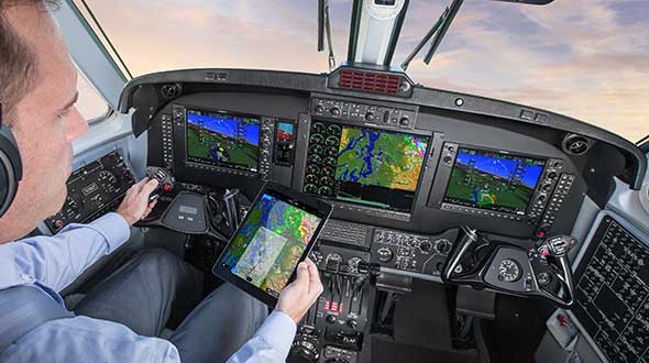
    Like when learning to sail offshore or to survive in the wilderness, a large component of any pilot training program is navigation. For flight simulators, this involves detailed aeronautical charts, huge amounts of Earth observation imagery including thousands of airports, and faithful replicas of several cockpit navigation instruments. While aviation programs provide standard training to ensure pilots can handle situations ranging from enemy fighters to bird strikes to engine failure, they may overlook the importance of duplicating actual cockpit instruments rather than relying on facsimile ones.

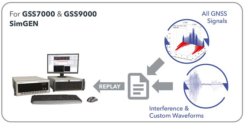
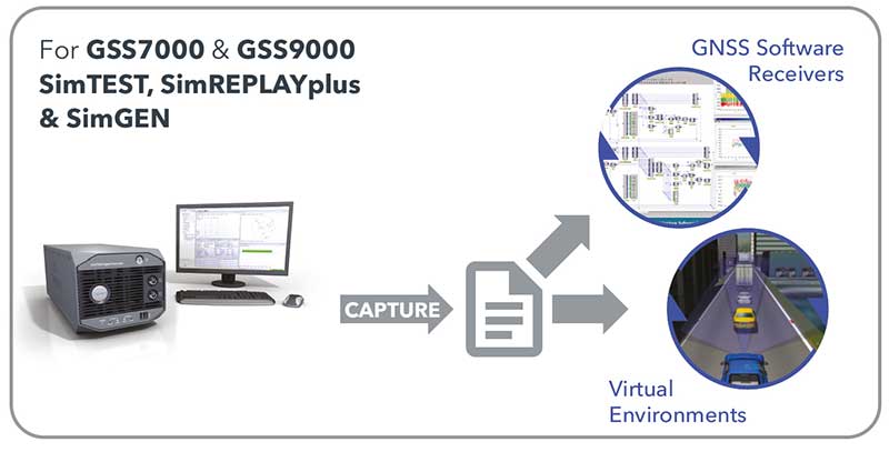
    Simulating GNSS signals

    This is where GNSS simulators come into play. They make it possible “to simulate the actual GPS signal required by the cockpit navigation instruments,” according to a case study by Orolia.

    This approach, the company points out, offers advantages to both the trainees who use flight simulators and the engineers who develop them. For a trainee, “the advantage is that he is trained using the identical instruments as those in the actual airplane […] providing the same feedback as a real-world experience.” For an engineer developing a flight simulator, GNSS simulators make it possible to “design more effective flight simulation programs without compromising quality.”

    Furthermore, “using real navigation instruments may […] reveal unexpected behavior from the instrument, which helps the pilot to be prepared for this possibility. If any conditions involving the plane dynamics are not properly handled by the navigation unit, the pilot can obtain actual feedback from real navigation instruments, which could differ from feedback provided by a facsimile instrument.”

    Hardware-in-the-loop (HWIL) techniques enable Orolia to integrate its simulator in a flight simulator to reproduce the GPS/GNSS dynamics for the airplane in real time. “Because the pilot steers the aircraft in real time, the GPS simulator must also simulate GPS signals in real time, forming an HWIL integration,” the company said. “This integration enables the flight simulator to integrate the actual navigation unit to provide a very realistic environment for the trainee.”

    Racelogic, another manufacturer of GNSS simulators, is launching a new RealTime LabSat that can connect to Microsoft Flight Simulator, including the new 2020 version. “This will create a live GNSS RF feed that accurately follows the trajectory in the simulator, enabling the testing of any GNSS device as though it were being flown on the aircraft,” said Julian Thomas, the company’s managing director. “To help make this a cost-effective solution, we have recently optimized our SatGen signal simulation software so that a real-time simulation such as this can be carried out on an entry-level PC with a full constellation of simulated satellites.”

    The GNSS and flight simulation industries overlap even further. For example, Garmin, which manufactures consumer GPS receivers, makes the avionics used in some professional flight simulators.

    Simulator demand on the rise

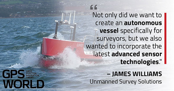
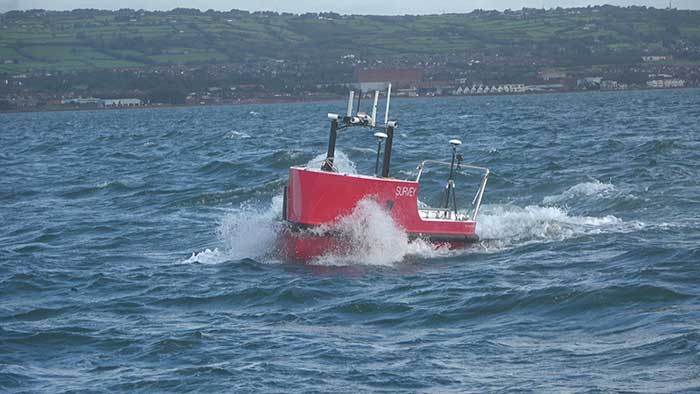
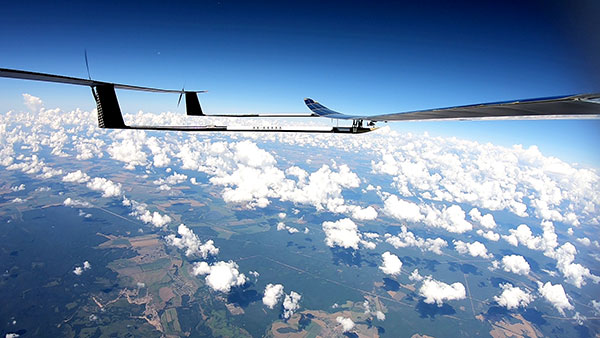
    The utility of simulators is not limited to training human pilots and drivers. The demand for simulation is being sharply increased by the development of autonomous vehicles of every kind — from self-driving cars to unmanned aerial vehicles (UAV), from bathymetric vessels to urban air mobility (UAM) aircraft.

    For example, manufacturers of self-driving cars need to simulate driving millions of miles, in all kinds of traffic and weather conditions, to perfect their vehicles’ algorithms. The result of all these simulations is better trained human and robotic pilots and drivers prepared for real situations, superior mission readiness, and maximum safety for both military and civilian operations on land, at sea and in the air.


    Feature image: In a simulated G1000 NXi integrated flight deck for a King Air 350, a pilot refers to the Garmin Pilot app, used as a supplement during flight. (Photo: Garmin)

  • Tallysman debuts mini embedded VeroStar GNSS antennas

    Tallysman debuts mini embedded VeroStar GNSS antennas

    Tallysman Wireless Inc. has added four new embedded VeroStar Mini products to its line of antennas. The ultra-compact and lightweight embedded VeroStar Mini models offer the same key features as the full-size VeroStar models but in a smaller, lighter package, with either a 90-mm (58 g) or 106-mm (69 g) integrated ground plane, both 32.4 mm in height.

    Innovation: Design and performance of a novel GNSS antenna for rover applications

    The VSM6028, VSM6028L, VSM6328 and VSM6328L embedded VeroStar Mini antennas are designed and crafted for high-accuracy positioning. With an exceptionally low roll-off from zenith to the horizon, VeroStar antennas provide the excellent tracking of GNSS and L-band correction signals at low elevation angles.

    The VSM6028 VeroStar antenna. (Photo: Tallysman Wireless)
    The VSM6028 VeroStar antenna. (Photo: Tallysman Wireless)

    Also, the optimized axial ratio at all elevation angles results in excellent multipath rejection, enabling accurate and precise code and phase tracking. Additionally, VeroStar antennas feature a robust pre-filter and high-IP3 LNA architecture, minimizing de-sensing from high-level out-of-band signals, including 700 MHz LTE, while still providing a noise figure of only 1.8 dB.

    The light and compact wide-band spherical antenna element enables the VeroStar Mini to deliver a ±2 mm phase center variation (PCV), making it suitable for high-precision applications such as autonomous vehicle navigation (land, sea, and air), smart survey devices, and maritime positioning.

    The VSM6028 supports the full GNSS spectrum (the VSM6028L includes support for L-band correction services), while the VSM6328 supports the GPS/QZSS-L1/L2/L5, GLONASS-G1/G2/G3, Galileo-E1/E5a/E5b, BeiDou-B1/B2/B2a, and NavIC-L5 signals and frequency bands (the VSM6328L includes support for L-band correction services).

    The unique features of the VeroStar Mini antennas guarantee it can deliver a high signal-to-noise ratio (SNR), high accuracy, and high precision in the most challenging environments.

  • Rohde & Schwarz provides testing for 5G LBS

    Rohde & Schwarz provides testing for 5G LBS

    Rohde & Schwarz supports 5G LBS with assisted GPS and 5G NR FR2 mmW performance testing

    Photo: Rohde & Schwarz
    Photo: Rohde & Schwarz

    Simulator and test company Rohde & Schwarz has verified assisted GPS (AGPS) performance in a commercial mobile device, while simultaneously transferring data using 5G millimeter wave (mmW). This capability is now available with the Rohde & Schwarz TS-LBS (location-based services) test system.

    As wireless network operators roll out 5G NR in the millimeter wave spectrum, it is critical to ensure continued reliability of E911 calls and accurate determination of location in mobile devices.

    5G NR utilizes frequencies in the FR1 frequency range (<7.125GHz) and in the FR2 mmW frequency range (>24GHz). FR2 creates unique challenges for mobile devices in terms of power consumption and heat. With FR2 becoming more common in North American mobile devices, performance of critical services such as E911 emergency calls cannot be allowed to degrade when utilizing this mmW spectrum.

    When used together in the TS-LBS test system, the R&S CMX500 radio communication tester and R&S CMW500 wideband radio communication tester provide a seamless and comprehensive test platform capable of testing LTE, 5G NR FR1 and FR2, while the R&S SMBV100B vector signal generator simulates the GPS L1 & L5, GALILEO, GLONASS & BEIDOU satellite constellations for A-GNSS.

    Other positioning technologies that use barometric pressure sensors, Wi-Fi and/or Bluetooth are also available in the same solution. Legacy technologies such as GSM, WCDMA and LTE are all supported using the same hardware.

    “The addition of FR2 mmW to our TS-LBS test solution gives customers the latest capabilities needed to continue certifying their mobile devices to evolving 5G standards,” said Bryan Helmick, Rohde & Schwarz. “Customers can easily add 5G to existing LTE TS-LBS systems with the simple addition of an R&S CMX500. FR2 support only requires some hardware on the R&S CMX500 and an R&S CMQ500 mmW shield cube.”

    5G NR in the sub 6 GHz frequency range (FR1) can be seen as a natural evolution of LTE to achieve higher bandwidth and more flexibility on the physical layer in order to realize all the new and additional use cases defined for a next-generation mobile network.

    The real technical challenge, however, comes with 5G mmWave (FR2), which opens up a new level of complexity in device development. mmWave frequencies imply measurement challenges that call for new testing approaches.