Apple has applied for a license from the Federal Communications Commission (FCC) to install GPS testing equipment within Apple Park.
For the purposes of licensing, GPS transmitters are included in radio broadcasting legislation, and enforced jointly by the FCC and the U.S. National Telecommunications and Information Administration, which is part of the Department of Commerce.
In its application, Apple named two objectives. The first objective is the “illumination of the part of the the facility, located at 1 Apple Parkway, Cupertino, California, with a GPS signal to allow for the testing and experimentation indoors for continued exploration of utilizing GPS technologies within their devices to provide innovation applications and continue to provide safe products.” Its second objective is the “further design, development and enhancement of existing GPS applications to provide greater efficiency and more effective means of utilizing GPS derived information.”
According to Apple Insider, this would mean Apple would install a GPS transmitter or repeater within Apple Park in order to better control and test its own GPS devices. Apple plans to use a GPS repeater called Metro GNSS, Apple Insider added.
The application has not yet been granted, but Apple previously applied three times for licenses to conduct tests regarding cellular and consumer radios, with each application being approved, reported Apple Insider.
Mobile World Congress (MWC) Barcelona will still take place Feb. 24-27, despite exhibitors dropping out because of the coronavirus. According to a statement by GSMA, some large exhibitors have decided not to come to the show this year because of the coronavirus, while others are still contemplating next steps. Despite this, the show is expected to boast more than 2,800 exhibitors.
According to Reuters, as of Feb. 9, there are two confirmed cases of coronavirus in Spain.
GSMA and its partners have implemented several safety measures for attendees, the organization said, including:
Increased cleaning and disinfection across all high-volume touch points, such as catering areas, surfaces, handrails, restrooms, entrances/exits and public touchscreens, along with the use of correct cleaning/sanitizing materials and products
Increased onsite medical support
Awareness campaign via online and onsite info-share and signage
Availability of sanitizing and disinfection materials for public use
Awareness and training to all staff on standard personal preventative measures, such as personal hygiene, frequent use of sanitizing/disinfection products, etc.
Advice to exhibitors on implementing effective cleaning and disinfection of stands and offices, along with guidance on personal hygiene measures and common preventive behavior
Public health guidelines and communication with Barcelona hotels, public and private transport, restaurants and catering outlets, retail, etc.
Installing new signage onsite reminding attendees of hygiene recommendations
Implementing a microphone disinfecting and change protocol for all speakers
Communicating advice to all attendees to adopt a “no-handshake policy”
A 24-hour telephone security and medical service for all attendees, available Feb. 12 to Feb. 29. This number will appear on the back of badge holders, in the event app and on signage around the venue.
Companies Back Out
Because of the coronavirus, several companies have backed out of attending MWC Barcelona. Several of these companies include Sony, Ericsson, LG, Nvidia and Amazon.
“Due to the outbreak and continued concerns about novel coronavirus, Amazon will withdraw from exhibiting and participating in Mobile World Congress 2020,” Amazon said in a statement. According to CNN Business, the company was due to host a dozen sessions covering topics such as 5G connectivity and artificial intelligence.
Other companies have expressed similar concerns.
“Sony has been closely monitoring the evolving situation following the novel coronavirus outbreak, which was declared a global emergency by the World Health Organization on January 30,” the company said in a statement. “As we place the utmost importance on the safety and wellbeing of our customers, partners, media and employees, we have taken the difficult decision to withdraw from exhibiting and participating at MWC 2020 in Barcelona, Spain.”
As an alternative, Sony’s press release will take place on Feb. 24 via a video through its official Xperia YouTube channel.
“We’ve informed GSMA, the organizers of MWC Barcelona, that we won’t be sending our employees to this year’s event,” Nvidia said in a statement. “Given public health risks around the coronavirus, ensuring the safety of our colleagues, partners and customers is our highest concern. We’ve been looking forward to sharing our work in AI, 5G and vRAN with the industry. We regret not attending, but believe this is the right decision.”
Drone service slated to begin February 2020, with goals of enhancing efficacy, reliability and predictability of delivering medical products between hospitals and laboratories.
In February, the University of California (UC) San Diego Health will launch a pilot project to test the use of unmanned aerial vehicles to transport medical samples, supplies and documents between Jacobs Medical Center, Moores Cancer Center and the Center for Advanced Laboratory Medicine (CALM), speeding delivery of services and patient care currently managed through ground transport.
Trained professionals will load and operate the drones, which will follow predetermined, low-risk flight paths and will carry no cameras. (Photo: UC San Diego Health)
The program is a collaboration with UPS, which received in September 2019 the Federal Aviation Administration’s (FAA) Part 135 Standard certification and authorization to use unmanned aircraft systems for a drone delivery program, and Matternet, a Mountain View, California-based drone systems developer for health care institutions. This latest effort builds upon the UPS and Matternet drone project already taking place at WakeMed Health and Hospitals, a private, non-profit health care system based in Raleigh, N.C.
“Currently, medical samples that must be transported between health care sites are carried by courier cars, which are naturally subject to the variabilities of traffic and other ground issues,” said Matthew Jenusaitis, chief administrative officer for innovation and transformation at UC San Diego Health. “With drones, we want to demonstrate proof-of-concept for getting vital samples where they need to be for testing or assessment more quickly and simply. It’s another way to leverage emerging technologies in a way that can tangibly benefit our patients.”
The project calls for medical professionals at Jacobs Medical Center, located on the east health campus of UC San Diego in La Jolla, to pack payloads, such as blood samples or documents, into a secure container that attaches to one of Matternet’s M2 rechargeable battery-powered drones.
The drones will follow predetermined, low-risk flight paths, initially between Jacobs Medical Center and special landing sites at Moores Cancer Center, located less than a mile away and within visual line of sight under the FAA’s Part 107 rules, and then subsequently at CALM, which is near the Jacobs Medical Center. The flights will take only minutes to complete and will be monitored by remote operators. The drones will carry no cameras.
In May 2018, the FAA designated the city of San Diego as one of nine lead participants in the regulators’ Integration Pilot Program. UC San Diego was also approved by the FAA to test the use of drones in transporting lab specimens and pharmaceuticals throughout its health system.
“Right now, most biological samples must travel between sites by courier car, within designated hours,” said James Killeen, MD, clinical professor of emergency medicine and director of information technology services at UC San Diego School of Medicine. “That leaves the system vulnerable to the vagaries of road congestion, accidents, construction and more. Travel time can be slow and unpredictable. A drone can fly over such obstacles in a much more direct way, and take just a few minutes to cover the same distance.”
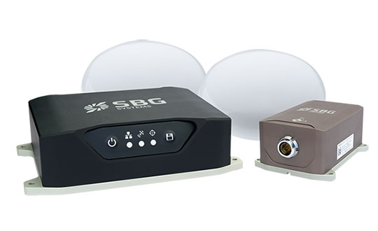
SBG Systems has opened a new subsidiary in Singapore. Located in the center of the city, this new office brings sales and technical support to the Asian region.
SBG Systems is a leading supplier of MEMS-based inertial measurement units (IMU) and inertial navigation systems (INS) for land, air and marine applications. The company has been developing its sales distribution channels in Asia for many years and has decided to bring sales and technical support closer to its clients and distributors by establishing a subsidiary in Singapore.
“We wanted to get closer to our customers and distributors in the region,” said Thibault Bonnevie, SBG Systems’ CEO. “By getting geographically closer, we wish to build closer relations with our esteemed customers and distributors and provide them with the highest quality service they deserve.”
The Singapore office will provide support to new and existing clients in the region with demonstrations, training and technical support.
Rooftop view of the central parts of Aarhus with the harbor area and the sea in the background. (Photo: DTU Space)
A testbed in an active urban center can show real-world effects on GNSS as an aid for developing autonomous systems for green mobility, smart-city applications or transportation, to name a few.
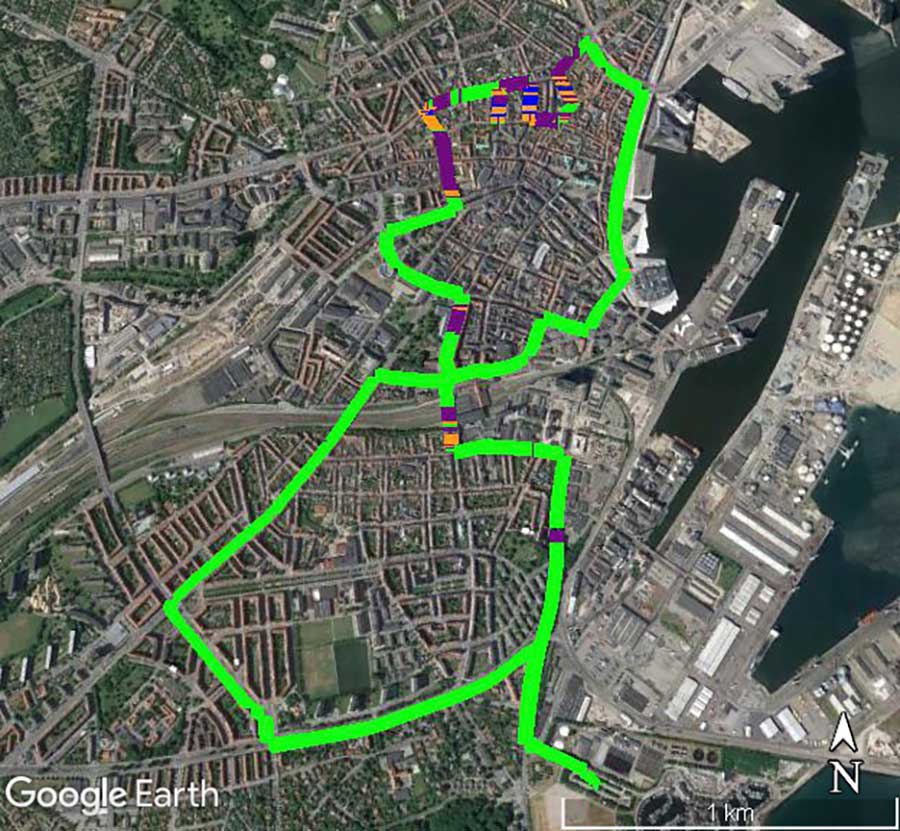
Sited in Denmark, the 600-square-kilometer Testbed in Aarhus for Precision Positioning and Autonomous Systems (TAPAS) covers both a densely populated city center and suburbs, a large industrial harbor and parts of Aarhus Bay. Aarhus is the second largest city in Denmark with a population of 350,000 people.
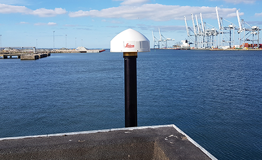
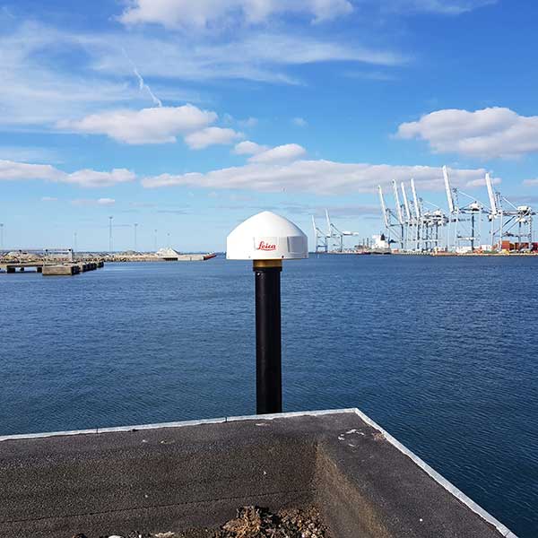
The GNSS antenna at TAPAS station TA01. (Photo: DTU Space)
Based on RTK methodology, TAPAS is a sound ground-based testbed to support, test and validate technological developments with a need for fast, efficient, flexible and reliable precision positioning. It is designed as a geodetic innovation platform, with both physical and virtual networks providing positioning to the centimeter (cm) level.
Autonomous systems within transportation, agriculture and environmental monitoring constitute a large growth area for businesses and governments. Automated vehicles, drones and vessels are linked closely to geodetic infrastructure and communications networks such as 5G. TAPAS provides developers in these fields with opportunities to observe GNSS in urban canyons and under canopies, as well as challenges for coastal marine applications. The testbed is available for third-party research projects, and testing of ideas, initiatives and concrete prototypes.
TAPAS is fully funded and owned by the Danish Agency for Data Supply and Efficiency (SDFE), the Danish agency for geodesy and geographical data. TAPAS is developed by the National Space Institute at the Technical University of Denmark (DTU Space), and is supported by the city of Aarhus. The TAPAS testbed was established partly because of Denmark’s National Space Strategy, which points to the new technological development within positioning, as well as possibilities for use of Galileo, the European GNSS, to the benefit of as many citizens as possible.
In this article, we review the TAPAS testbed, including design and installation of the GNSS reference stations and the data-processing center, as well as initial performance testing carried out by DTU Space.
Network of GNSS Reference Stations
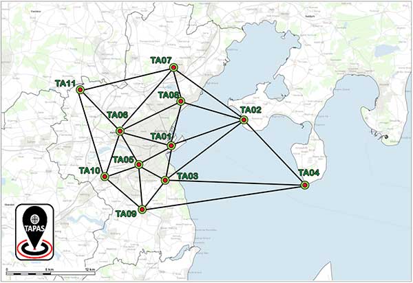
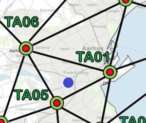
The network of TAPAS stations in and around the city of Aarhus in Denmark. (Map: DTU Space)
The basic component of TAPAS is high-accuracy carrier-phase-based GNSS positioning using the network RTK methodology, which can provide real-time position accuracies for the end user down to the cm level.Essentially, TAPAS is based on a network of 11 GNSS reference stations as well as data communication infrastructure, a central processing facility with a data server, processing software and data storage.
TAPAS was designed to provide real-time position uncertainties for objects in motion within 1 cm in three dimensions (1 cubic cm), for end users with modern GNSS equipment. A dense network of GNSS reference stations was originally designed with stations 5 km apart in the city center and up to 10 km apart in the suburbs.
Because suitable locations had to be found, in the final network distances range from 4.1 km to 22.3 km, with the longest distances across the water to station TA04 (see the network plot in the graphic above).
Stations TA01, TA03, TA05, TA06 and TA08 are in the city center. Stations TA02 and TA04 are across Aarhus Bay, ensuring coverage for marine applications and contributing to more robust positioning near the sea and in the harbor area around station TA01.
TAPAS Stations
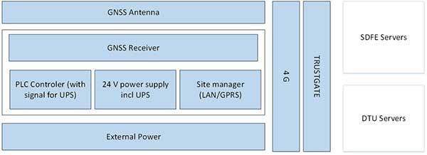
The TAPAS GNSS reference stations are equipped with the newest generation of GNSS receivers and antennas capable of tracking all available signals from the GPS, GLONASS, Galileo and BeiDou systems. The stations also have an antenna splitter, power supply, fuse box, programmable logic controller (PLC) for monitoring and control, trustgate, modem and uninterruptible power supply with battery pack (Figure 1). All units were integrated in the cabinets and tested in the lab before installation The stations are modular and flexible for future iterations and updates.
The receivers can be accessed remotely via a VPN line to a web interface for monitoring, changing settings or firmware updates. All TAPAS stations transmit data to servers at DTU Space where the data is used for estimation of RTK corrections. Also, data is transmitted to servers at the SDFE for storage and backup (Figure 1).
Figure 1. Design schematics of the TAPAS stations. (Image: DTU Space)
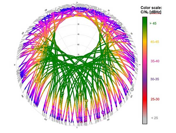
After installation in the fall of 2018, GNSS data quality was verified for each station by estimating preliminary positions and analyzing data quality. Also, signal strength as given by the carrier to noise ratio (C/N0) of the received signals was analyzed and plotted with 24 hours of data from each of the stations (Figure 2).
Network Real-Time Kinematic (RTK)
Data from the TAPAS stations streams in real time to the Central Processing Facility (CPF) operated at a dedicated server at DTU Space in Lyngby, North of Copenhagen. The GNSS observations are processed using the GNSMART 2 software from Geo++, where corrections for network RTK positioning are estimated. The corrections are estimates for errors affecting the GNSS positioning, such as inaccuracies in satellite positions and clock drift parameters as well as ionospheric and tropospheric effects. The dense network of reference stations in TAPAS will assure that corrections for the atmospheric effects will be of very high quality.
For estimation of the RTK corrections, standard software settings are used. All corrections are estimated by a state space representation (SSR) technique, where error sources are modeled individually. This means TAPAS can deliver both RTK corrections and corrections for precise point positioning (PPP).
TAPAS corrections are generated in the RTCM format and output using the NTRIP protocol. Registered users can access the corrections through the internet via an NTRIP caster. On the user side, the TAPAS corrections are applied in the positioning process of a GNSS receiver. To make full use of the TAPAS data, user equipment should be capable of tracking carrier-phase-based GNSS data and applying the TAPAS correction data supplied in the RTCM version 3.x format.
An example of a use of TAPAS is provided in the photo in Figure 9 below where the authors of this article tested the position accuracy of TAPAS for a typical land surveying task, using a Septentrio Altus APS3G receiver with an allegro2 controller unit for RTK positioning. The user’s GNSS equipment can, however, be many other different types and makes of GNSS antennas and receivers, and the equipment can be installed on many different platforms for instance in vehicles, on drones, in robots etc.
Geodetic Basis
When determining positions with uncertainties at the 1-cm level, it is important to be aware of the geodetic reference frame used for the positioning. In this case, coordinates for the TAPAS stations have been estimated by DTU Space, using Bernese GNSS software, in the national Danish reference frame which is a realization of the European Terrestrial Reference System (ETRS).
When applying corrections from the TAPAS caster in the positioning calculations at the user side, positions will be obtained within the same reference frame (coordinate system). In this case, where the national geodetic reference frame is used, this means that the user will obtain positions compliant with maps, charts and other types of geodata geo-referenced in the same coordinate system.
For 3D positioning, the Danish geoid model must be applied on the user side to obtain heights relative to mean sea level in the national Danish Vertical Reference (DVR90).
It is possible to configure the setup of the central processing facility using another reference frame for TAPAS given that precise coordinates for the TAPAS stations can be provided in the given reference frame. Future work with TAPAS can involve the use of dynamic geodetic reference frames and transmission of coordinate transformation parameters to the users.
Performance Testing
After the stations were installed, DTU Space conducted performance testing, including testing data communication between the TAPAS stations and the TAPAS server, analyses of data completeness from the TAPAS stations, and field tests carried out after the network RTK processing had become sufficiently stable.
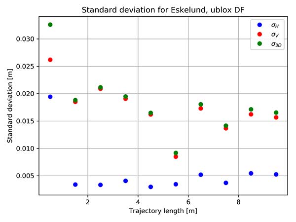
Performance test in static mode. In February 2019, a static mode test took place in a park-like area within the three innermost stations. Two different high-accuracy survey-grade RTK-receivers were used for the field test. RTK positions were estimated at 1 Hz for 30 minutes. For each minute, an average position was calculated based on the 60 observations, and for each of the minute-bins the standard deviation with respect to the reference position was computed.
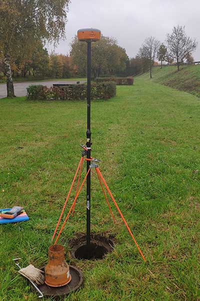
Test location indicated with purple circle in the network plot. (Image: DTU Space)Altus APS3G unit mounted at the test location. (Photo: DTU Space)
The results are shown in the plots below, where standard deviations are provided for each epoch (i.e., for each bin of 60 seconds).
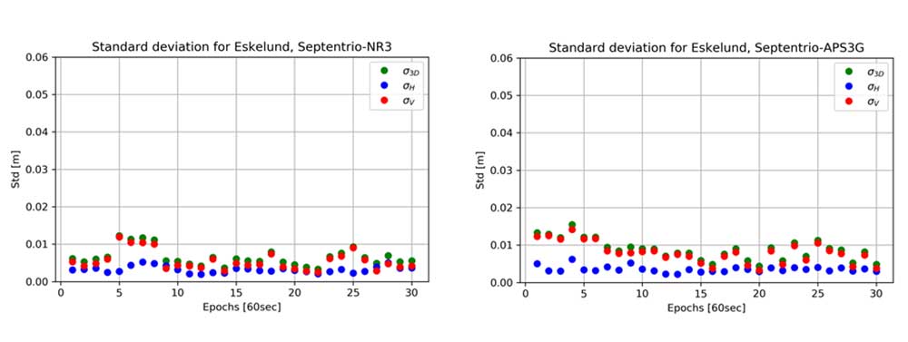
Standard deviation in meter for each 60 second with GNSS receiver Altus NR3 (left) and Altus APS3G (right). Results provided in meter. (Images: DTU Space)
In the plots, results are provided for the vertical (red), the horizontal (blue) and the 3D position (green). Results of using the two different receivers are comparable, and focusing on the 3D solutions the largest standard deviation is 1.6 cm which is for the fourth epoch with receiver APS3G. Most of the 3D results shown in the plots are better than 1 cm.
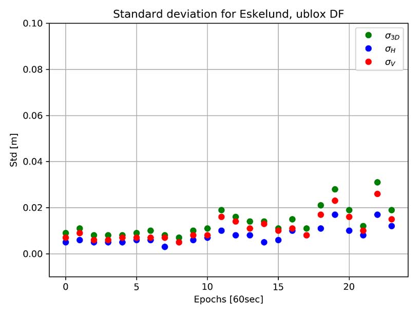
The same test was carried out using a dual-frequency non-survey-grade receiver developed for machine control and autonomous vehicle applications. This receiver was connected to the same antenna mounted on a tripod. Results of using this receiver in static mode are shown in the plot below. In this case, the 3D results are all better than 3.1 cm, and many of the 3D results are better than 1 cm in this open test area.
Standard deviation for each 60 second with GNSS receiver u-blox F9P dual frequency (DF). Results provided in meter. (Image: DTU Space)
Performance test in kinematic mode. In the same area used for the static test, a kinematic test was carried out with the same three receivers.
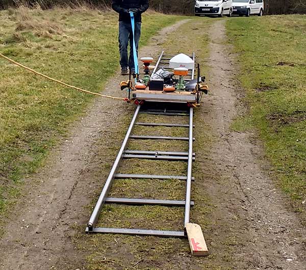
The test was performed using a camera dolly and by placing approximately 10 m of rail on the ground. The camera dolly was pulled back and forth along the rail, a setup that provided a stable trajectory for testing positioning performance while the GNSS antennas were moved slowly and smoothly. A rigid bench, where the GNSS antennas could be mounted, was constructed and installed on the dolly. The three GNSS receivers with antennas were mounted on the bench, and the dolly was pulled back and forth along the tracks 10 times.
Kinematic Test: Camera dolly with GNSS equipment pulled along tracks. (Photo: DTU Space)
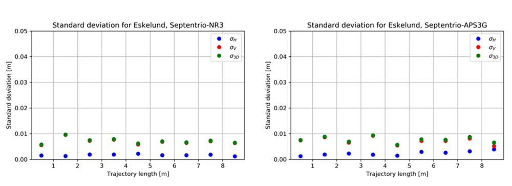
For each 1-meter section of track, the standard deviation of the differences with respect to the reference trajectory of the 10 repetitions was calculated. Results for the two survey-grade receivers are shown in the plots in Figure 3. All of the 3D standard deviations are better than 1 cm for both survey-grade receivers.
Figure 3. Kinematic test results are provided for the vertical (red), horizontal (blue) and 3D (green) positions. (Image: DTU Space)
The non-survey-grade dual-frequency receiver also was mounted on the test bench, and the results of using this receiver are shown in the plot below. With this receiver, the 3D results are below 2.1 cm for all sections of the trajectory, except for the first meter, a deviation that may have been caused by issues with initialization of the test.
Binned standard deviation of 10 repetitions with GNSS receiver u-blox F9P dual frequency (DF). Results provided in meter. (Image: DTU Space)
These tests show that it is possible when using TAPAS to obtain position solutions at the cm-level in open areas in both static and kinematic mode.
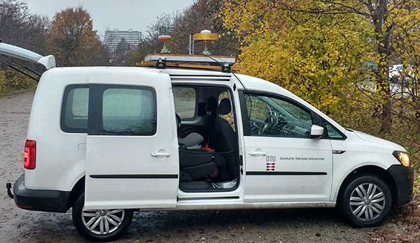
Performance test in dynamic mode. In November 2019, DTU Space carried out a performance test of TAPAS in dynamic mode, using a car with roof-mounted GNSS equipment. The car was driven within the TAPAS coverage area, passing through urban canyons, open streets and the harbor area. During the test, the car drove in normal Aarhus traffic, at speeds varying from zero at traffic lights up to 60 km/h on the wider roads leading into the city center.
Four different receivers were strapped in the car and connected to either a small patch antenna or a survey-grade antenna mounted on the roof. A survey-grade receiver was mounted on the roof.
Three different GNSS antennas mounted on the roof of the car used for dynamic testing. (Photo: DTU Space)
Data from the receiver was converted to KML files, which can be used with Google Earth to illustrate the quality of the positioning obtained during the drives through the city. The plot in Figure 4 shows the quality of the position solution. The best quality is obtained when the ambiguities are fixed, such as an RTK fixed solution at the cm level (green). The second-best quality is with ambiguities estimated to float values, such as an RTK float solution at the dm level (purple). Orange shows differential position solutions at the meter level when corrections for the carrier-phase data have not been obtained. Finally, a few positions were stand-alone GNSS solutions when no aiding from TAPAS was applied in the roving GNSS receiver (blue).
Figure 4. Quality of RTK positions obtained during one drive through the City of Aarhus. (Map data: Google, TerraMetrics)Photo:
The plot clearly shows, as expected, that the quality of the positions determined by the survey-grade receiver in the car is good most of the time. But it suffers in areas with narrow streets aligned with buildings or trees.
These results do not tell the actual uncertainty of the position solutions. But GNSS carrier-phase data collected with one of the receivers in the car during the drive will be post processed to serve as a reference trajectory. Upcoming analyses of the data will then reveal the uncertainty of the positions determined in real time as compared to the post-processed reference trajectory.
Test Conclusion. After the field tests, we conclude that the TAPAS testbed is able to provide correction data that makes it possible to perform GNSS-based positioning in real time in both static and dynamic mode with position uncertainties at the cm-level. Further, as we analyze the test data thoroughly, TAPAS will be able to set a tone for new research. For instance, the plot in Figure 4 provides a foundation for testing assistance procedures to gain better coverage in the most densely built areas. In this way, TAPAS will aid research into feasible infrastructure for the technologies of tomorrow, such as autonomous driving.
Outlook and Future Work
Because TAPAS is not commercial, it is possible, upon agreement with the SDFE, to make changes to the system to adapt to specific testing or development needs. Examples are removing data from some stations in the estimation of RTK correction data, installing an extra receiver in one or more stations using the antenna splitters, or making changes to the settings in data processing on the TAPAS server for shorter time intervals.
At DTU Space, plans for the testbed include further development of software for ionosphere and integrity monitoring. The station receivers can estimate total electron content (TEC) along the GNSS signal path in Earth’s atmosphere, as well as indices for ionospheric scintillation. DTU Space is researching using this output for an ionosphere monitoring service and to develop it into an integrity monitoring service for GNSS users.
Upcoming additions to the RTCM data format will support more advanced modeling of the effects of the ionosphere and troposphere, and this will allow for full benefit of the TAPAS SSR network corrections. Research on such models to be applied on the server side, as well as on the user side, will be carried out by DTU Space and tested with TAPAS as a contribution towards the integration, or hybridising, of PPP and RTK. This is also referred to as PPP-RTK positioning which is expected to be especially useful for mass market applications such as autonomous driving. When implemented in TAPAS, such solution may effectively increase the number of simultaneous users as well as use-cases for TAPAS.
TAPAS provides many opportunities for testing precision or high-accuracy applications, such as autonomous vehicles, vessels, drones and robots; location-based services requiring high accuracy on various digital platforms; and solutions for a more digitized and intelligent city environment through smart-city and green mobility initiatives.
TAPAS is prepared for the implementation of the coming 5G technologies, and station intercommunication capabilities enable testing of internet of things (IoT) technologies where precision positioning is part of the development. The testbed also provides an excellent environment for validation of new services such as the Galileo High Accuracy Service (HAS). Another area in which TAPAS can play an important role is verification and validation of future 5G-based positioning services.
The TAPAS testbed was developed with close cooperation between DTU Space and SDFE. SDFE contributors include Kristian Keller, Casper Jepsen, Henrik Olsen, Martin Skjold Grøntved, Brigitte Rosenkranz, Maria Rask Mylius and Søren Fauerholm Christensen. DTU Space contributers include Ole Bjerregaard Hansen, Finn Bo Madsen, Lars Stenseng, Daniel Haugård Olesen, Stefan Emil Steffensen, Thor Heine Snedker, Per Knudsen and Niels Andersen.
Manufacturers
The GNSS receivers at the TAPAS stations are Septentrio PolaRx5S, and the antennas are Leica AR20. For field testing, a Septentrio Altus NR3 receiver, a Septentrio Altus APS3G receiver and a u-blox ZED F9P dual-frequency receiver were used. The TAPAS station cabinets were assembled and mounted by Nordtec-Optomatic A/S. The TAPAS testbed software solution is based on the GNSMART 2 software package from Geo++ GmbH. Data analyses and processing has been carried out using the Septentrio SBF Analyser and SBF Converter, the RTKlib and the Bernese GNSS software.
Anna B. O. Jensen is senior advisor and team lead of the GNSS group at DTU Space in Denmark. She is also a part-time professor at KTH Royal Institute of Technology in Sweden.
Per Lundahl Thomsen is a chief consultant at DTU Space. He has many years of experience with management of space technology projects and is project manager for the TAPAS testbed.
Søren Skaarup Larsen is a Ph.D. student at DTU Space. Along with his GNSS studies, he runs the RTK-part of the TAPAS testbed.
URISA’s GIS Hall of Fame honors persons and organizations that have made significant and original contributions to the development and application of GIS concepts, tools or resources, or to the GIS profession.
URISA is inviting nominations for 2020 inductees.
Anyone may nominate a person or organization for induction to URISA’s GIS Hall of Fame. To make a nomination, submit a written statement to URISA describing:
The nominee’s achievements, emphasizing significant and original contributions to the development or application of GIS concepts, tools, or resources, or to the GIS profession; and
The significance of the nominee’s contributions, in terms of their enduring impact on the GIS field or profession, and their social benefit.
Hall of Fame laureates are expected to exemplify vision, leadership, perseverance, community-mindedness, professional involvement, and ethical behavior.
Nominations are due on or before May 11. The 2020 URISA GIS Hall of Fame celebration will take place during GIS-Pro 2020 in Baltimore, Maryland.
Visit the URISA website for details about the nominations criteria and process, and to review the path-breaking accomplishments of previous inductees.
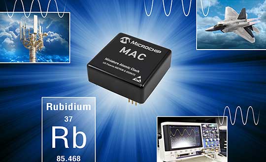
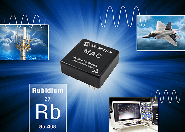
Microchip releases MAC-SA5X, enhancing its miniature atomic clock (MAC) technology to deliver wider temperature range and rapid warm-up time
As reliance on precise frequency and timing increases due to GNSS enabling 5G communication networks, data centers and other mission critical infrastructure, smaller size and high-performance atomic clock technology has become essential to supporting both military and commercial applications.
To meet demand for a small-footprint atomic clock, Microchip Technology released a higher performance atomic clock for its size and power. The new device also delivers a wider thermal range, critical performance improvements and other enhancements over previously available technology, the company said.
Next-Gen Timing. Microchip’s next-generation MAC-SA5X miniaturized rubidium atomic clock produces a stable time and frequency reference that maintains a high degree of synchronization to a reference clock, such as a GNSS-derived signal.
Its combination of low monthly drift rate, short-term stability and stability during temperature changes allows the device to maintain precise frequency and timing requirements during extended periods of holdover during GNSS outages or for applications where large rack-mount clocks are not possible.
Image: Microchip
Operating over a wider temperature range of -40 to +75 Celsius, the MAC-SA5X was designed to quickly achieve atomic stability performance by taking less time to lock compared to some of the existing clock technology, Microchip said. In an aircraft application, for example, these attributes enable faster power up of critical communication and navigation systems in extreme climates.
The MAC-SA5X allows system developers to avoid the need for extra circuitry by integrating a one pulse per second (1PPS) input pin for fast frequency calibration, saving time and development cost. In addition, the MAC-SA5X is designed with the same footprint as previous generation miniature atomic clock technology, reducing the development time to transition to the newer, higher performance device.
“As an industry leader, Microchip continues to invest in next-generation atomic clock technology for Department of Defense programs, mission-critical infrastructure and networks that require a high degree of accuracy in timekeeping and synchronization,” said Randy Brudzinski, vice president and general manager of Microchip’s frequency and time business unit. “The MAC-SA5X adds several performance and feature enhancements while retaining the same footprint as the previous generation MAC-SA.3X products, enabling customers to easily transition to the new technology.”
Designed and manufactured in the U.S., the MAC-SA5X operates to the following additional specifications:
<5.0E-11 frequency stability over operating temperature;
<5.0E-11 per month aging rate; 6.3-watt power consumption;
47 cc in volume.
The MAC-SA5X provides backward compatibility with its predecessor MAC-SA.3Xm family and comes in an ovenized crystal oscillator (OCXO)-sized package of 50.8 mm x 50.8 mm.
Microchip has delivered more than 275,000 rubidium clocks, 120,000 chip-scale atomic clocks (CSACs), 12,500 Cesium clocks and 200 active hydrogen masers to customers worldwide.
Development Tools. The MAC-SA5x family of atomic clocks is supported by evaluation kit 090-44500-000.
Availability. The MAC-SA5X atomic clock is available now for pre-sampling, and will be available for deliveries in February. Microchip supports the MAC-SA5X with technical support services as well as an extended warranty.
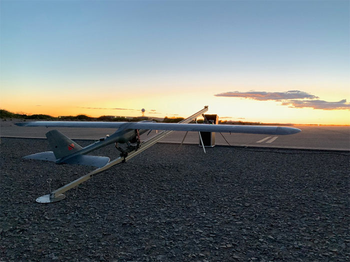
According to the company, the E1 is a solar electric, fixed wing unmanned aircraft system. It has a 20-pound payload capacity and a ceiling of 20,000 feet above ground level. It’s ideal for consumers who do not have the expertise to operate their own UAS, as SFUAS provides full service as well as sales, the company said.
The Silent Falcon E1 features 12 different sensor types, is vibration free and is beyond visual line of sight capable with a live feed. It also boasts four- to 12-hour duration configurations.
In addition, Silent Falcon has an application pending before the Federal Aviation Administration for type certification of the E1.
“Successfully passing 500 hours of flight is a significant milestone for the E1, confirming for federal regulators that it is a safe and durable aircraft model,” Silent Falcon said in a press release.
The full line of SFUAS products, services and support is now available via GSA Contract No. GS07F248BA, the company added.
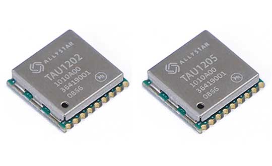
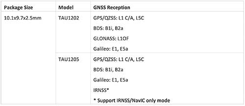
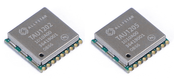
Allystar Technology Co. Ltd. has launched the dual-band multi-GNSS modules TAU1202/TAU1205, which support both the L1 and L5 bands to enhance sub-meter positioning accuracy. Constellations received include GPS, Galileo, GLONASS, BeiDou, QZSS and IRNSS.
Besides the L1 band, TAU1202 and TAU1205 also support L5/B2a/E5a, which are expected to have lower noise and significantly reduced multipath mitigation because of the higher chipping rate of L5 signals relative to L1 C/A code.
Chart: Allystar
TAU1205 supports IRNSS (NavIC) which makes it suitable for navigation in the urban areas of India and the Middle East, as there are seven NavIC satellites with a higher elevation than both GPS and Galileo satellites.
Photo: Allystar
Powered by Allystar Cynosure III GNSS chipset and with built-in low-noise amplifier and surface acoustic wave (SAW) filter, TAU1202 and TAU1205 provide higher sensitivity, ensuring exceptional acquisition and tracking performance even in weak signal areas.
Based on 40-nm manufacturing processes of the Cynosure III GNSS chipset and state-of-the art internal PMU, TAU1202/TAU1205 comes with very low power consumption at less than 40 mA.
Multiple communication interfaces including UART and I2C simplify customer designs and provide a better time-to-market for customers’ products.
“Due to its excellent performance in urban area, compact design and concurrent multi-GNSS reception, TAU1202/TAU1205 has become a popular selection for vehicle and asset tracking in worldwide,” said Zhang Yanping, Allystar product line manager. “The launch of TAU1202/TAU1205 shows Allystar continues to drive GNSS evolution in thte navigation mass market.”
Allystar started TAU1202/TAU1205 mass production in the second half of 2019.
The International Wireless Communications Expo (IWCE), set to take place March 30 to April 3, will key in a number of industry topics, including 5G, FirstNet, drones, artificial intelligence, augmented reality, wearables and push-to-talk communications.
IWCE will also feature a drone demonstration area and safe cities section. The event is designed for those in the critical communications industry, including first responders, police enforcement, fire departments and government.
According to show organizers, more than 7,000 people are expected to attend the five-day event. IWCE will also include educational workshops, short courses, power sessions, keynote addresses, town hall meetings and networking events. The event tracks will include 5G, safe cities, in-building wireless, connectivity and public safety broadband, among several others.
Chief Jeffrey Johnson, CEO of the Western Fire Chiefs Association, will present the keynote speech, titled “The innovations that are actually changing street performance for responders.” Other speakers will include Bryan Wiens, senior product manager, Cloud Services, InterTalk Critical Information Systems; Michelle Geddes, public safety communications director, city and county of San Francisco’s Department of Emergency Management; Robert Zanger, wireless engineering and operations unit at the Department of Justice; and more.
“Since its inception, IWCE has provided an opportunity for all those who work within the sector to stay ahead of all the latest developments,” said Stacey Orlick, IWCE conference director. “Attendees can learn about the latest developments in safe cities, new infrastructure that affects utilities and transportation, in-building wireless systems, technology advancements and the latest regulatory insights that they should be aware of.”
The contract begins the offering for the purchase of complete drone solutions to all state agencies, commissions, political subdivisions, institutions and local public bodies allowed by law.
DroneUp is an end-to-end drone pilot service provider for aerial data collection. In August 2019, the company was awarded the Unmanned Aerial Systems (UAS) Services Master Agreement #E194-79435 by the Commonwealth of Virginia.
The services under this latest award (Contract Number #2020DRONE0002) are available for use by all 50 states, the District of Columbia, and the territories of the United States through the National Association of State Procurement Officials (NASPO) ValuePoint Cooperative Purchasing Organization.
The State of Alaska is now able to use the award for the benefit of state departments, institutions, agencies, political subdivisions, and other eligible entities.
DroneUp’s award includes but is not limited to service categories for
Emergency Support Services,
Law Enforcement Support,
Aerial Inspection or Mapping Data Services,
Agricultural and Gaming, and
Agency Media Relations and Marketing.
Primary users are expected to be
Agriculture & Game Management,
Emergency Management,
Transportation,
Forestry,
Mines,
Minerals and Energy, and
Public Universities and Community Colleges.
“We appreciate the efforts to streamline public sector access to leading-edge UAS services through the contract with the State of Alaska, and we look forward to supporting our hardworking state and local agencies,” said Tom Walker, DroneUp’s CEO.
The use of drones for precision agriculture is gaining momentum because of their capability to deliver the most updated information fast and efficiently. UAVs are transforming how agriculture is done. By implementing drone technology, farms and agriculture businesses can improve crop profit, save time, and make land-management decisions that improves long-term success.
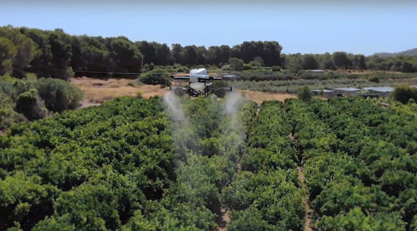
A few weeks ago Quaternium tested its innovative HYBRiX drone to spray fertilizers in the orange fields near Valencia, Spain. With its system of longer-than-average flight-duration, farmers have the opportunity to monitor and spray their fields precisely and rapidly.
“I am really glad to see that the entire spraying process in my orange fields has hardly taken six hours,” said farmer Pedro Andreu while operating the HYBRiX. “With other drones, we had to spend multiple hours waiting for batteries to charge and days to finish the work.”
The test convinced Andreu to use the technology to simplify his work. He engaged farmers in the neighborhood to join him and implement this technology in their work as well.
Alicia Fuentes, Quaternium CEO, accompanied the team for the field demonstration. She noted that farmers could benefit by using precision farming technology in a variety of ways: monitoring the health of their crops, estimating soil conditions, planting future crops, fighting infections and pests, updating the health of plants, and livestock monitoring.
Hybrid fuel system. HYBRiX UAS operates using a hybrid electric-fuel system. This makes it easy to operate the multi-rotor drone through the fields of a farm for an entire work whole day by refilling the spraying tank when needed and the fuel tank every 2-3 hours. Its built-in capacity of 5 liters of fuel enables HYBRiX to surpass the flying time from minutes to 2 to 4 hours.
The powerful propulsion system of HYBRiX allows the aircraft to carry up to 10 liters of liquid, with a maximum takeoff weight of 25 kg. The combination of hybrid power with its increased range extender capacity allows the farmer to cover large acres of land without carrying uncomfortable batteries and ensure long flight time in the field with the aircraft.
Quaternium is now focused on refining this technology to extend crop protection across the country so that farmers can benefit from the outcome to make their work more efficient.