Grand Sky Business and Aviation Park and Harris Corp. have joined forces to enable the country’s first and largest unmanned aerial system (UAS) airspace to support beyond visual line of sight (BVLOS) flight operations and UAS Traffic Management (UTM) research.
Stretching up to 100 miles, this BVLOS “super corridor” is the most technologically sophisticated UAS airspace supported by multiple and redundant systems for cooperative and non-cooperative surveillance.
These surveillance capabilities make possible a wide range of UAS BVLOS applications in precision farming, oil and gas, infrastructure inspection, public safety, package deliveries, and others.
“Customers of Grand Sky will have access to a truly unique UAS operational capability, in addition to better facilities, comprehensive airspace surveillance, and wide operational areas,” Grand Sky Development Co. President Thomas Swoyer Jr., said. “We all benefit from efficient and safe BVLOS flight operations and a larger corridor with proven FAA collaboration and flight authorizations.”
The surveillance system combines data feeds from a network of advanced sensors and towers. Two long-range primary radars located at Grand Forks Air Force Base and at Hillsboro, North Dakota, provide detection of non-cooperative aircraft.
The Federal Aviation Administration (FAA) secondary radars and ADS-B network in the region, as well as local Harris ADS-B Xtend sensors, add additional layers of visibility for cooperative aircrafts in the airspace.
Aviation-grade displays help pilots and electronic observers monitor the airspace environment over the BVLOS corridor and safely steer UAS from approaching manned aircraft.
The combination of best practices in aviation safety management, proven technologies and experience with BVLOS regulatory approvals will make it easy for users of the airspace to advance UAS technology commercialization and routine, efficient flight operations.
UAS operators can work with Grand Sky and Harris to develop, test, and refine a variety of complex BVLOS concepts of operations and secure waivers from the FAA for large-scale use.
A full range of UAS operations can be supported for all types and sizes of unmanned aerial vehicles along the BVLOS corridor including a variety of airspace classes and execution of diverse defense, civil and commercial applications.
“This is another first for Grand Sky and North Dakota in leading the UAS Industry,” Harris Vice President and General Manager of Commercial UAS Solutions George Kirov said. “The size and complexity of the airspace opened to UAS BVLOS operations is unmatched in the UAS industry. The sophistication of the Harris BVLOS system at Grand Sky is also unprecedented — linking Harris’ most advanced suite of surveillance and detect-and-avoid services with a variety of surveillance assets that, together, ensure the highest level of UAS aviation safety.”
This partnership lays the foundation for larger and more capable surveillance corridors to enable UAS “highways” across the state of North Dakota and in support of expanding the variety of commercial UAS operations across the United States.
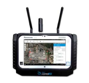
Mobilicom’s SkyHopper VU remote viewing terminal is specifically designed for commercial and industrial drones and robotics. (Photo: Mobilicom)
Mobilicom Ltd., a global mission-critical-communications solution provider, will present its SkyHopper end-to-end solutions for smart drones and robotics at the Association for Unmanned Vehicle Systems International’s Xponential 2019 trade show.
According to the company, SkyHopper brings all the key components that turn a drone into a smart drone. The SkyHopper product suite includes communication data links, cybersecurity and encryption that has been validated by the Israel Ministry of Defense and other government organizations; video processing; controllers and viewers.
The product line includes the SkyHopper PRO bi-directional data link, SkyHopper PRO V integrated video processing, SkyHopper ControlAir ruggedized controller and the SkyHopper VU remote viewing terminal.
According to the company, the SkyHopper PRO bi-directional data link delivers long range and non-line of sight communication that supports multiple transmission modes. The SkyHopper PRO V includes a dual-camera input, three camera interfaces, dual built-in video encoders and decoders, and local recording ability. The SkyHopper ControlAir allows users to control a drone or robot, as well as transmit or view a video and data while operating in air and ground missions. Finally, the SkyHopper VU offers a mobile HD video and telemetry receiver terminal for multiple viewers, specifically designed for commercial and industrial drones and robotics.
“We have done our homework in understanding what our customers need in order for their drones to successfully execute their missions,” said Oren Elkayam, CEO of Mobilicom. “As a result, while others focus on offerings for today, we offer solutions also essential for the future survival and scalability of commercial drones of robotics. With proprietary drone cybersecurity and radio technology and a highly experienced customer success team, SkyHopper has maintained a strong base of over 50 customers and counting.”
According to Mobilicom, its goal is to enable commercial drone and robotics manufacturers to increase their chances for success by focusing on their own business objectives, reducing time to market and minimizing resource expenditures.
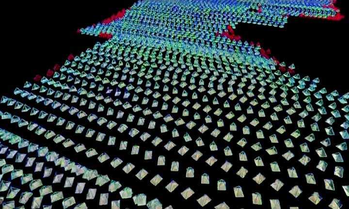
The National Trust for Scotland commissioned Glasgow-based GeoGeo to carry out a drone survey of the inner Hebridean islands of Canna and Sanday in November 2018. Using an ultra-high-definition camera, the GeoGeo team not only pinned down the exact locations of archaeological features, but also revealed new archaeological sites.
Over five days,the drone navigated 400 kilometers to capture 4,000 images at a 3-centimeter resolution. After processing, the images created a minutely detailed 3D map capable of being used in a 3D printer to create scale models of the islands. With more than 420 million data points, it is currently the world’s largest complete island dataset captured by drone, claims GeoGeo founder Paul Georgie.
Screenshot: GeoCue
“We were blown away by the results and the possibilities of this technology,” said Derek Alexander, head of Archaeology at the Trust. “We’ve previously recorded archaeology on Canna and Sanday which proves that there were inhabitants as far back as the Neolithic, but this survey gives us information and detail we just haven’t had until now. We’ve been able to obtain exact plots of known sites, but also recorded the extensive traces of cultivation, such as rig and furrow field systems that range in age from the Bronze Age onwards.”
Screenshot: GeoCue
The cameras and software also will be able to help with seabird counts and habitat and coastal erosion monitoring, which are currently expensive and labor intensive, Alexander said. The trust will use the maps to update archaeological records and prepare for future groundwork and excavations.
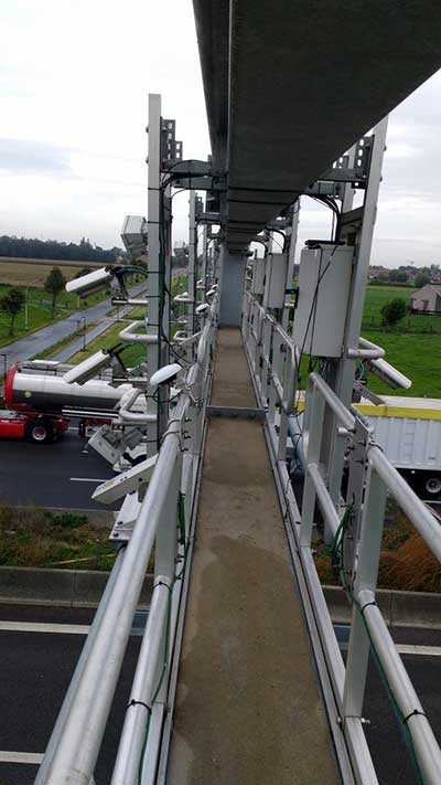
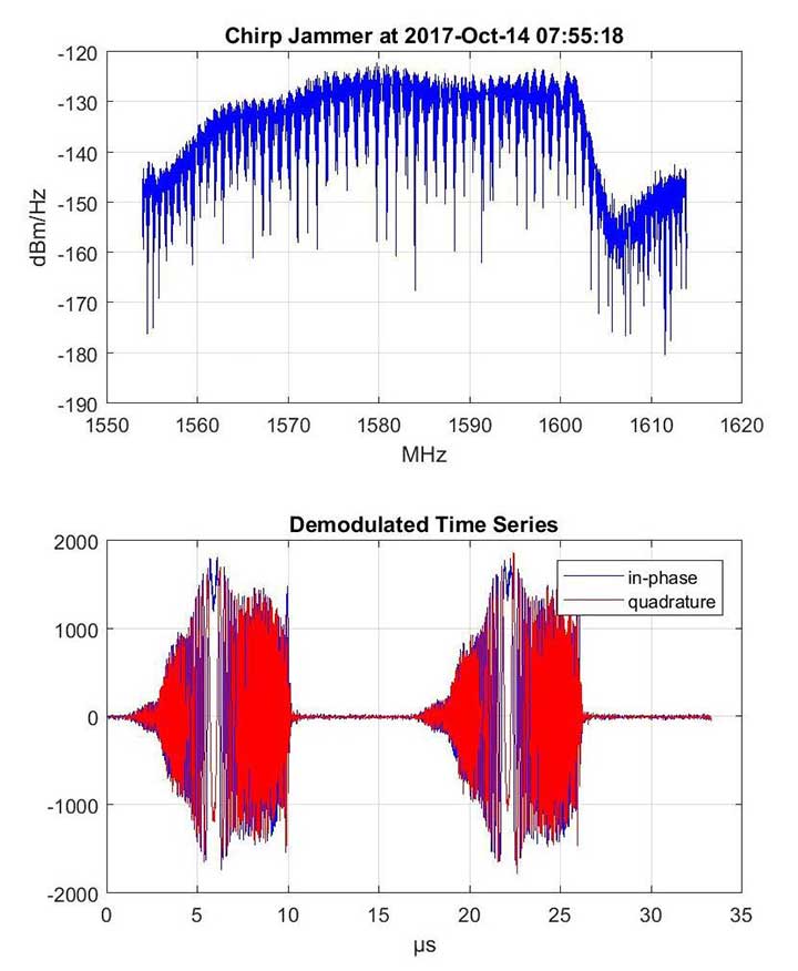
Recent years have seen an increase in drivers turning to cheap GNSS jamming devices in order to move around undetected or to thwart built-in anti-theft systems or road tolling systems. These jammers not only knock out their own GNSS receiver, they also block GNSS signal reception in a radius of several hundred of meters.There is a growing demand for automatic detection of these illegal jammers to help catching the offending driver.
Septentrio GNSS antenna placement on highway gantry. (Photo: Septentrio)
An ION GNSS+ 2018 presentation by Wim de Wilde and Jean-Marie Sleewaegen presentation showed how a multi-antenna GNSS receiver with built-in RF spectrum monitor and adequate processing tool can efficiently detect and classify jamming events and identify the offending car or truck. They conducted a five-day test with two Septentrio AsteRx-U dual-antenna receivers installed on an overhead structure above a busy highway.
In parallel to the GNSS tracking and built-in anti-jam functionality, the AsteRx-U can simultaneously sample the RF signal from its two antennas. One of the objectives of the test was to evaluate the possibility to perform lane detection by cross-correlating the jamming signal received by the two antennas. In addition, the antennas were mounted with a significant inclination angle to create an asymmetrical reception pattern.
The goal was to assess the feasibility of detecting the driving direction from the time series of the received jammer power. Such lane or direction detection would greatly help identifying the offending driver in heavy traffic conditions when more than one vehicle crosses the overhead structure at the time of the jamming.
Over the five days of the experiment, 45 jamming events were recorded and analyzed, most of them intentional: continuous wave, chirp or even less-known pulse jammers.
Chirp jammer example. (Charts: Septentrio)
The researchers explained how the jamming events are automatically detected and classified by the processing tool, using pattern recognition to distinguish between intentional harmful events and unintentional interferences. They presented selected cases illustrating the RF signature of the most prevailing types of jammer.
They then addressed the direction and lane sensing algorithm and discussed the effect of multipath propagation of the jammer signal. All algorithms are illustrated with real-life examples.
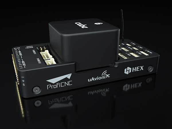
uAvionix has announced a partnership with autopilot maker CubePilot to integrate ADS-B IN receive capability into its carrier board.
uAvionix is the designer and manufacturer of communications, navigation and surveillance (CNS) equipment for unmanned and manned aircraft.
CubePilot is the designer and manufacturer of the “The Cube” autopilot (formerly known as Pixhawk) for unmanned aircraft systems (UAS).
The new carrier board, available in July, integrates uAvionix’s custom ADS-B silicon for 1090-MHz ADS-B reception for worldwide detect and avoid (DAA) functionality.
With this integration, UAS operators will be able to see nearby ADS-B OUT enabled aircraft on ARDUPILOT’s Mission Planner, providing the remote pilot in command (RPIC) with timely notification to take the necessary actions to remain well clear.
CubePilot, which uses the open-source ARDUPILOT platform, previously provided plug-and-play functionality for several uAvionix ADS-B IN and OUT products, including PingRX, Ping2020i and Ping1090i. Support for these products is retained in the new design, allowing for 978MHz ADS-B reception or integration of ADS-B OUT functionality.
“With this partnership, uAvionix furthers our goal of ensuring safety and common situational awareness between airspace users,” states Christian Ramsey, uAvionix president. “We believe that ADS-B IN functionality should be a requirement for every DAA system for UAS operations over people or beyond visual line of sight, and meeting that requirement should not be cost prohibitive.”
“The safe integration of UAS into the National airspace of any country needs to take a safety-first approach from all players,” said Philip Rowse, Hex/ProfiCNC (CubePilot) CTO. “By partnering with uAvionix and including the ADSB-in at practically no cost to the customer, we remove the cost barrier, adding safety to our customers’ UAS solutions.. We envisage this added situational awareness, and optional auto avoidance behavior will be an important step towards safely shared skies.”
Visit uAvionix at AUVSI Xponential in Chicago April 30-May 2 at Booth 4421 and CubePilot at Booth 1816.
Household size distributions are critical inputs to many business analyses, but may not be correctly derived from U.S. Census data, according to Caliper.
The Census counts people at their geographic locations, and when several unrelated people live at the same address, they are reported as one household with a number of residents.
A confusing array of data is reported. In both the Census SF1 2010 file and in 2017 ACS, the following tabulations are provided down to the Census tract level:
People in Family Households
2 person Family Households
3 person Family Households
4 person Family Households
5 person Family Households
6 person Family Households
7+ person Family Households
Non-relatives in Family Households
Unmarried Partners (including same-sex couples) in Family Households
People in Non-Family Households
Unmarried Partners (including same-sex couples) in Non-Family Households
There is also extensive information on people residing in group quarters in the 2010 Census, which has the tabulations below:
People in Group Quarters: College
People in Group Quarters: Military
People in Group Quarters: Navy Ships
People in Group Quarters: Other
People in Group Quarters: Homeless
People in Group Quarters: Group Homes
People in Group Quarters: Residential Treatment
People in Group Quarters: Merchant Ships
People in Group Quarters: Workers’ Group Living Quarters
People in Group Quarters: Other Other
People in Group Quarters: Institutionalized
Using this information, Maptitude 2019 includes a corrected data set of household size distributions for Census Tracts and Block Groups to account for the under-representation of one-person households in the Census data.
Census tracts with Caliper derived households. (Image: Caliper)Census tracts with Census household count. (Image: Caliper)
SimActive Inc., a developer of photogrammetry software, announced that Correlator3D is being used for mapping projects in Brittany, France, by Altimedias.
An eBee X equipped with senseFly S.O.D.A. 3D camera is flown along the shoreline to produce high-resolution true orthomosaics and 3D models.
“The quality of outputs from Correlator3D is exceptional and the mosaic renders the vivid colours of the Pink Granite Coast,” said Didier Wasselin, COO at Altimedias, which specializes in drone data collection and processing. “Such results are very useful for heritage conservation and decision making by local authorities.”
“The combination of SimActive software and senseFly eBee Plus X is an ideal combination, due to the accurate RTK/PPK and optimized aerial triangulation,” said Francois Gervaix, technical advisor at SimActive. “The S.O.D.A. oblique imagery leads to outstanding 3D textured models.”
SBG Systems will present its Quanta UAV series at AUVSI’s Xponential show, which takes place April 30-May 2 in Chicago. The Quanta UAV series is a line of inertial navigation systems (INS) dedicated to UAV-based surveying integrators.
Because SBG Systems wants UAV surveyors to save autonomy for additional survey lines, the company has designed a small, lightweight, and low-power INS offered on two levels of accuracy. Quanta UAV and Quanta UAV Extra have been developed for compact lidar to high-end BVLOS mapping solutions. They provide precise orientation and centimeter-level position data delivered both in real time and post processing. This direct geo-referencing solution eliminates the need for ground control points and greatly reduces the need of overlapping.
Qinertia, SBG’s post-processing software completes the Quanta UAV offer. It gives access to offline real-time kinematic (RTK) corrections from more than 7,000 base stations in 164 countries, the company said. Trajectory and orientation are greatly improved by processing inertial data and raw GNSS observables in forward and backward directions. This advanced software also computes the base station position to quickly provide centimeter accuracy. Qinertia comes free for one year with the Quanta UAV sensor.
Robotics and surveying. Quanta UAV is the result of SBG’s expertise in both miniaturized technology for drone navigation and high-end sensors for mobile mapping. Designed as a geo-referencing solution, it can also be used as a high-end navigation solution to feed the UAV autopilot.
Quanta UAV benefits from a tight integration with in-house IMUs, advanced calibration techniques and algorithms that ensure consistent behavior in all weather conditions, as well as robust position even if the UAV gets close to buildings, electrical lines or trees.
Quanta UAV embeds a web interface for an easy configuration with a 3D view showing all parameters. The calibration tool automatically aligns the lever arm between the two antennas and the sensor, and re-estimates it in flight for more precision.
The ITAR-free Quanta UAV INS are available for order.
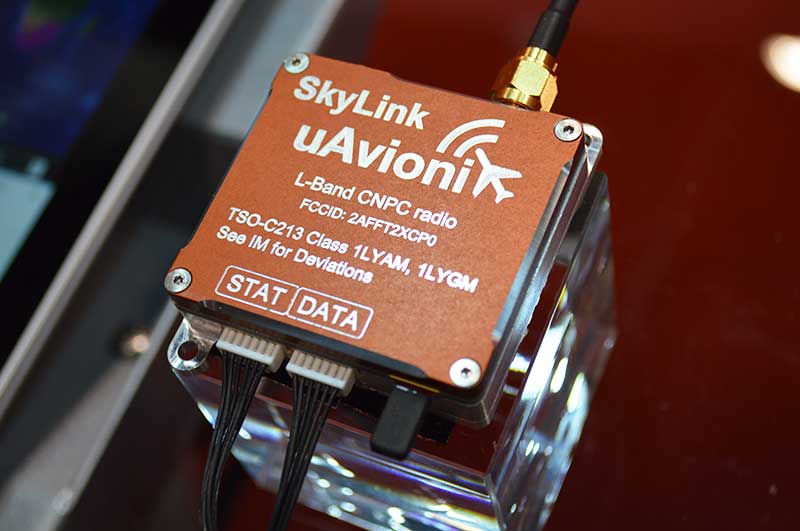
uAvionix, designer and manufacturer of communications, navigation, and surveillance (CNS) equipment for unmanned and manned aircraft, is testing its prototype of a command and non-payload control (CNPC) radio for unmanned aircraft systems (UAS) and urban air mobility vehicles.
Photo: Allison Barwacz
SkyLink is an L-band frequency-modulated CNPC radio ultimately intended for point-to-point or networked Beyond Visual Line of Sight (BVLOS) UAS operations. uAvionix has focused on minimizing size, weight, and power consumption (SWaP) while maximizing range and spectrum efficiency.
The current 50-gram 10-Watt prototype is testing successfully at ranges exceeding 40 miles at low altitude. uAvionix is testing under an experimental transmit license and approval from the Federal Communications Commission and Federal Aviation Administration, respectively.
Prior to founding uAvionix, CEO Paul Beard invented and brought to market the Spektrum digital spread spectrum radio control (RC) technology which moved the control link from 27 and 72 MHz bands to a high-bandwidth 2.4-GHz ISM band.
“Building high performance datalinks for airborne applications is insanely challenging,” said Beard. “Combining our ability to produce TSO certified equipment with the experience of developing and deploying millions of commercial products globally with Spektrum, we expect to bring affordable, scalable, and safe solutions to enable the UAS and UAM markets.”
Written by William Tewelow, GISP and Co-written by Jon Gustafson, GISP
Significant focus on infrastructure asset delivery and lifecycle must become a priority so that architects, engineers and construction (AEC) can leverage BIM systems for design, construction and management solutions.
Innovations in BIM applied to infrastructure construction projects will enable “smart” solutions. This article explores BIM for infrastructure insights and brings attention to closing the BIM divide between the vertical (buildings) and the horizontal (linear) infrastructure industries, such as roads, bridges and pipelines.
For smart systems to be applied to infrastructure, CAD needs to evolve to the point where those multi-dimensional models can integrate with geographic information systems (GIS). The larger the project, the more necessary it is for a seamless data transition from the local engineering scale to the municipal, regional or national reference systems.
Autodesk defines building information modeling (BIM) as an intelligent 3D model-based process that gives architecture, engineering and construction (AEC) professionals the insight and tools to more efficiently plan, design, construct and manage buildings and infrastructure.
It is like a GIS in many respects, but applied locally to a structure. It is able to do many common geospatial calculations. It is still an evolving technology, but it is clear that soon it will do for AEC and facilities management what GIS did for surveying and cartography.
A smart move
Systems have evolved augmenting our abilities with built-in applications that can integrate connected data and systems to enhance and extend our capabilities. These systems are termed smart, which has become the newest marketing buzzword.
Everything is getting the smart label. Along with the label is an expectation that the lines between the physical and the digital worlds are blurring as we slip ever nearer the veil wherein we will simultaneously co-exist in both worlds.
Smart also infers it is connected to the digital cloud, that seemingly infinite expanse measured by petaflops, into which artificial intelligent algorithms augment everything with contextually aware information overlaid atop our own experience of the world.
Of course, this view has its pitfalls and cautionary tales, and every step we take into the future we lose some connection with the past. For example, everyone can use a calculator, but are times tables even taught anymore? Automation leads to complacency.
When CAD was unimaginable
Let’s take a brief look backward. The year was 1978, my second year of high school. I took drafting class as an elective and would end up doing so for the rest of the time I was in high school, accumulating enough credit hours to graduate with a vocational degree equivalent in architectural design. Those were the days of drafting tables, slide rules, French curves, triangles, keen eyes and steady hands.
The last year of school, there was talk of something called computer-aided drafting or design (CAD) that would make all we were doing obsolete. It seemed impossible at the time. Especially after I took a brand-new summer course called computer programming. Computers were large, heavy, clunky things that had limited abilities. They were basically responsive text machines. Program something in BASIC, save it, and then from the DOS command window, run it over and over again.
I remember reams and reams of green and white paper two foot wide fed by geared teeth, and pages of pages of our coded programs that we would have to pour over looking for the mistake in the line of code. And, this long and lengthy code was merely to archive and sort information or make the computer draw a cat or some other object using “X”.
We would all stand around the dot matrix printer as line by line the image took shape on the printed page. There was that wondrous feeling of success creating something having first conceived it in the mind then, like digital-smiths, forging it in a non-physical space and holding it in our hands. But I could not understand how that blinking white cursor on a black screen could ever replace the rich colors and smoothed lines of the beautiful architectural drawings I had spent years learning.
I felt confident the stories of our trade being overtaken by CAD were greatly exaggerated. That lesson taught me that change is inevitable and far beyond our rational ability to comprehend what is possible based on our current understanding. I watched as computer-aided design did take over, giving engineering and architectural drawings multidimensional context.
Horizontal lags behind
Now, let’s jump back into the present. The horizontal industry is behind the vertical industry with respect to project management deliverables. In part, this disparity will be aided by the Geospatial Data Act which was passed into law on Oct. 5, 2018.
The linear model is approximately 10 years behind the vertical model, especially for above-ground assets and facilities. However, recent technology advancements — augmented reality (AR), unmanned aircraft systems (UAS), indoor lidar and modeling software — and influential advocacy initiatives (such as public agency innovation programs like smart cities) are starting to enable digitally integrated management of asset information more holistically. Indeed, there is urgency for these linear systems to be adequately captured.
The Feb. 6 explosion from a ruptured gas line in San Francisco showed the dangers of not having an adequate map of the subsurface infrastructure. Fortunately, no one was injured, but damage from subsurface infrastructures can be deadly like the San Bruno disaster in 2010.
Gas line explosion damage in San Bruno, California. (Image: U.S. Department of Transportation)
The “Call Before You Dig” law was enacted for this very reason. At the very least, problems with linear infrastructure can negatively impact a city’s quality of life and budget such as a water main break or a broken sewer line.
Looking ahead 5-10 years, horizontal infrastructure designers and installation companies will use 3D modeling tools as standard practice in an open data sharing environment allowing other networks to access the information and add it to their own projects.
Imagine a county’s 811 system, the universal number to call before you dig, and instead of calling, it is an app on a users’ phone. A requester submits a short form and receives a text when the application is approved, usually within minutes, and is then able to view an augmented reality overlay of the subsurface infrastructure in the vicinity beneath the ground where the requester’s project is taking place.
This approach has economic benefits, providing faster turn-around times, increasing citizen engagement and improving the safety of communities. Over time, it is a “collect once and use many times” system — it will reduce demand on city staff and billable hours, saving cities money.
The same technology is also available for construction projects, providing schematics to see pipes, ducts and wires in walls, floors and ceilings. This is not science fiction. Existing condition data is already being collected in 3D, so it is logical to anticipate engineering design will be prompted to support ongoing 3D collection efforts and begin doing work in 3D.
Using BIM from the outset of a project builds this into a system that can be accessed later. However, the use of these advanced augmented reality technologies are limited to certain geographic areas with enough funding and technical capabilities. This is primarily in large urban areas, new growth areas, and redeveloping areas of a city; however, large infrastructure projects such as pipelines, railroads, highways, bridges and hyperloops will have to develop high-resolution models that will capture some of the surrounding areas and benefit all communities along the routes helping to bridge the disparity of the BIM divide.
In time, as costs come down and the technology improves and becomes easier to use, all communities will benefit from and incorporate this emerging technology.
Photo: Krauchanka Henadz/Shutterstock.com
BIM for intelligent infrastructure: sensors and structures
Critical to BIM for smart infrastructure is the fusion of sensors, data and infrastructure. Sensors will be embedded within and affixed to physical assets for the purposes of collecting data and self-monitoring for machine learning, maintenance and repair. Networking internet-enabled devices that actively and passively sense is at the core of the internet of things (IoT). Data from these IoT devices will improve physical asset management, creating unique opportunities for agencies, especially when considering how machine learning can discern patterns in data to detect anomalies, and improve safety such as self-aware systems that can heat road surfaces when precipitation is detected in below-freezing temperatures.
The digitizing of the physical world will take place with greater demand for higher resolution capabilities. Physical structures will require an exact computerized replica, referred to as a Digital Twin. An effort is underway by the Open AR Cloud Organization (OARC) to create an open standard for this digital twin of the world, so that applications and innovation will not be hampered by proprietary systems.
Yohan Baillot, CEO of ARcortex and founder of the Open AR Cloud, explained if there is no open standard, something developed in one system may not align with applications viewed in another system. This could be costly and disastrous for transportation and construction projects. Point in case would be the above example of Call Before You Dig,if a gas pipeline is incorrectly depicted and a work crew ruptured it.
This Digital Twin is both a high-resolution GIS and a basemap for both vertical and linear BIMs to connect into. Knowing the location of subsurface assets is foundational to the increasing investment into smart cities, which is forecast to become a $3.5 trillion industry within the next seven years.
David Rouse (2017) defines smart cities as cities that use information and communication technologies to increase operational efficiency, share information with the public, and improve both the quality of government services and public well-being. Using smart devices, communication among the devices and with the entities managing those devices provide deeper insight on device behavior and the ability to develop algorithms to change device parameters using other sensors in close proximity.
All of this data can be used to optimize asset performance over time. In the U.S., San Francisco, New York, Chicago, Los Angeles, Boston and San Jose all have active smart city projects advancing connectivity (Nominet 2018).
Intelligent infrastructure augments users’ abilities by the multiplicity of sensor arrays (self-monitoring devices, RFID, Wi-Fi, GPS receivers, cameras, etc.) communicating with decision-support systems as well as other sensors — the internet of things (IoT). For instance, high mast cameras combined with artificial intelligence algorithms for object recognition deployed along a stretch of highway allows stakeholders to extract important insights of that physical asset (such as surface condition, traffic flows and vehicle counts) and provide that information in real time to emergency response crews, police and security, maintenance vehicles, network-connected vehicles and others.
Digital integrations
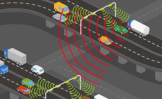
Intelligent transportation systems are entering the next generation enabling vehicle-to-infrastructure (V2I) interactions. The U.S. Department of Transportation (2018) website states,
V2I technologies capture vehicle-generated traffic data, wirelessly providing information such as advisories from the infrastructure to the vehicle that inform the driver of safety, mobility or environment-related conditions. State and local agencies are likely to install V2I infrastructure alongside or integrated with existing ITS equipment.
The Open Connectivity Foundation (OCF) endeavors to provide open standards and certification to make connectivity easier, more reliable and more secure by bridging IoT ecosystems.
Specifically, OCF specifications can be used to develop vehicle data model translators that enable remote fleet management for autonomous vehicles, OBD device interactions (vehicle performance monitoring) and crowdsourcing of data models for continued development (Open Connectivity Foundation 2018). Currently, many transit agencies are seeing growth in equipping rolling stock with IoT devices including GPS, Wi-Fi and traffic light preemption, which improves fleet optimization and data accessibility, and enables better congestion management as well as increased system performance (American Public Transportation Association 2018).
Crowdsourcing data from web-based and mobile applications is a popular public engagement mechanism. Crowdsourcing at its most basic level is the aggregation of (big) data from a large group of people. From an asset management perspective, leveraging the general public’s direct and indirect collection of data brings deep insight into asset performance and condition.
The data collected provides the ability to better plan transportation systems with demand modeling, predictive analytics, event response times to identify those impacted and determine where additional capacity is needed, and to provide personalized services (such as through email and text) including weather-related events impacting the commute.
Applications such as Waze empowered the public with the ability to report hazards, construction zones and other concerns on the road and shoulder that DOTs can use to dispatch resources to address the situation/issues quickly. Furthermore, Alavi and Buttlar (2019) identified sensing capabilities of smartphones and their crowdsourcing power for monitoring several distinct civil infrastructure systems such as pavement.
Conclusion
In summary, BIM for infrastructure overlaying a robust GIS plays a critical role for supporting advanced technologies for integrating dynamic IoT and crowdsourced data.
Infrastructure asset owners are encouraged to recognize the importance of BIM-oriented policy and practices and invest in required initiatives that make incremental progress towards a smart infrastructure vision.
BIM is the foundation of intelligent infrastructure and defines the backbone of smart cities.
References
Alavi, Amir H., and William G. Buttlar. 2019. “An overview of smartphone technology for citizen-centered, real-time and scalable civil infrastructure monitoring.” Future Generation Computer Systems 93: 651-672. https://doi.org/10.1016/j.future.2018.10.059.
Jon Gustafson, PS, CFedS, PMP, GISP is a management consultant with one of the world’s largest professional services companies, WSP (https://www.wsp.com). He is an accomplished business-oriented technical professional consistently recognized as an industry leader in multi-jurisdictional land surveying practice, geospatial policy development and program/project management. He helps his clients address infrastructure technology deployment challenges by developing effective recommendations/guidelines focused on advancing civil integrated management practices and innovations. Some recent projects include developing data governance strategies for major infrastructure programs, conducting applied research on digital project delivery initiatives, advancing UAS integration, and formulating geospatial technology strategies for a public agency.
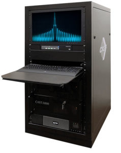
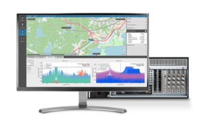
The CAST-5000 produces a single coherent wavefront of GPS RF signals to provide repeatable testing in the laboratory environment or anechoic chamber. The basic system generates four independent, coherent simulations that reference a single point and is upgradeable to support seven elements for CRPA testing. With an intercard carrier- phase error of less than 1 millimeter, the CAST-5000 is extremely accurate.
The system generates a wavefront of GPS when its GPS RF generator cards are operated in a ganged configuration. Each generator card provides a set of GPS satellites coherent with the overall configuration. Several RF generator cards may be utilized together, ensuring phase coherence among the bank of signal generator cards.
The CAST-5000 Controlled Reception Pattern Antenna (CRPA) tester allows a full end-to-end test of the antenna system. The CRPA antenna, antenna electronics and the GPS receiver can be tested as a unit with or without radiating signals.
The CAST-8000 is a new simulator that merges both the CAST-5000 CRPA tester with a CAST-3000 EGI tester.
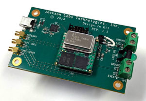
The tiny 1-inch square Micro-Transcoder module allows glueless retrofitting of existing GPS equipment with secure and Assured-PNT (A-PNT) capability. It is the smallest, full-constellation, stand-alone, real-time 10-channel GPS simulator available from JLT. The unit is useful in upgrading existing legacy GPS receivers with external position, navigation and timing references such as INS, CSAC, SAASM, M-code, GNSS, eLoran or other alternative positioning and timing sources by simply replacing the legacy GPS antenna from an existing GPS system with the Micro-Transcoder RF output.
The unit is based on the JLT CLAW GPS Simulator and RSR Transcoder technologies, and includes a general-purpose, stand-alone, full-constellation, 10-channel, real-time GPS simulator with integrated high-stability timing reference, as well as an internal GNSS receiver for monitoring the RF output signal for quality and accuracy. The unit will transmit a standard UTC time, position, velocity and heading GPS L1 C/A RF signal by simply applying 3.3V power to it.
The Micro-Transcoder can also be operated as a generic GPS simulator with built-in GPS Disciplined Oscillator (GPSDO), and is supported by a free Windows application downloadable from the JLT website. The Windows application allows control of all the simulation aspects, creating and storing simulation vector commands and testing user equipment for leap-second and GPS week rollover event compatibility to identify weaknesses in user equipment. The unit does not require a connected PC to function. The Micro-Transcoder is also available mounted onto an evaluation board for easy evaluation. The unit transcodes baseband PNT NMEA signals into a GPS L1 RF signal with typically less than 100-ms latency. UTC 1PPS timing-transfer accuracy to the GPS RF output is typically better than 5 ns. The unit requires only 3.3V to operate, and setup, location and simulation vector file information can optionally be stored in its internal NV memory.
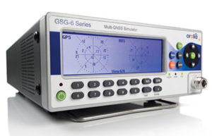
For those responsible for mission-critical PNT applications, the Orolia GSG series of GPS/GNSS simulators is an important tool to evaluate risk for jamming, spoofing or any other threat. Orolia GSG-5/6 series simulators are easy to use, feature-rich and affordable, offering a way to harden GPS-based systems without the limitations of testing from “live sky” signals. The Orolia platform approach allows customers to buy only what they need today and upgrade later. The adaptability of the GNSS RF generation platform can extend to applications for intelligent repeating.
Test Solutions
Position accuracy and dynamic range/sensitivity
Simulate movements/trajectories anywhere on or above Earth
Sensitivity to GPS impairments: loss of satellites, multipath, atmospheric conditions, interference, jamming and spoofing
Conducted or over-the-air RF
GPS time-transfer accuracy
Effect of leap-second transition
Multi-constellation testing
Modernization signals/frequencies
Keyless military SAASM, dual-frequency and survey-grade receiver testing
Infrastructure possibilities include zone-based indoor location (intelligent repeating) and pseudolite applications.
GSG-6 Series 64-channel multi-frequency, advanced GNSS simulator is powerful enough for any cutting-edge test program. GPS, GLONASS, Galileo, Beidou, QZSS and NAVIC (IRNSS) signals are available across multiple frequencies. The GSG-6 is designed for military, research and professional applications.
GSG-5 Series 16-channel multi-constellation L1-band GNSS simulator is designed for commercial development/integration programs. It is for developing commercial products with GNSS capability, and will shorten test programs with confidence.
GSG-51 single-channel signal generator is designed for one purpose — fast, simple go/no-go manufacturing test and validation, ensuring the manufacturing line is operating at full capacity with confidence in quality.
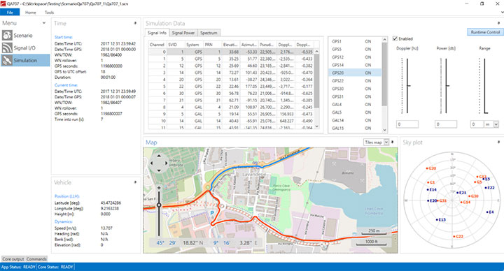
Specifically designed for testing GNSS interferences and cyber-attacks. QA707 has been designed to test robustness against emerging cyber-threats beyond jamming and spoofing. It allows the creation of scenarios with signal and code jamming, data-level cyber-attacks, denial of service threats, low-level spoofing channels control, and trajectory-controlled spoofing.
Optimal for signal modernization design. Being a flexible software defined radio (SDR) solution, QA707 is also suitable for testing of signal modernization and for the simulation of new signal components. An open API is provided to create specific signals simulation. Particularly, the tool is ready to support the upcoming Galileo Open Service Authentication (OSNMA).
Runs on a standard PC or laptop with USRP or other hardware. QA707 is compatible with several third-party hardware RF up-converters, including National Instruments’ USRP. It also can support customer’s specific hardware through the hardware API interface. Qascom introduces the new frontier of GNSS security testing. QA707 is supported from back office with custom services as well as jamming and spoofing mitigation solutions for receivers and applications. This covers 100% of customer GNSS security needs.
QA707 Main Features
Multi-constellation (GPS L1, Galileo E1, SBAS L1)
Galileo OSNMA ready
RF simulation, binary file dump, signal record and replay
Support to SDR platforms and open API for custom RF upconverters
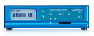
The LabSat 3 Wideband is easy to use, cost-effective and produces extremely low noise, accurate and repeatable signals. Users can record and replay up to three different channels at 56 MHz with a bit depth of up to 3 bits I and 3 bits Q.
The following signals can be recorded and replayed:
2X CAN, RS232, and digital inputs recorded and replayed tightly synchronized with GNSS data
Small, battery or mains powered and with a removable SSD (up to 4 Tb), LabSat 3 Wideband allows detailed, real-world satellite data to be recorded then replayed on the bench. The rugged enclosure measures a compact 167 x 128 x 46 millimeters and weighs 1.2 kilograms, meaning it can be placed in a backpack and used to reliably record real-world signals in almost any situation.
SatGen Signal Simulation Software
If a user wants to simulate the signals from scratch, Racelogic’s latest SatGen signal simulation software can produce synthesized scenarios containing the full complement of popular GNSS signals: GPS L1, L2C, L5, GLONASS L1, L2, Galileo E1, E5, E6 and BeiDou B1, B2.
SatGen software allows users to quickly create accurate scenarios with their own time, place and trajectory, with any combination of constellation and signal that is currently available or will become available in the near future.
Precision-sensitive applications such as autonomous driving, control of unmanned aerial vehicles (UAV), or positioning of aircrafts during landing procedures in coordination with ground-based augmentation systems (GBAS) require that modern GNSS receivers undergo detailed tests before implementation.
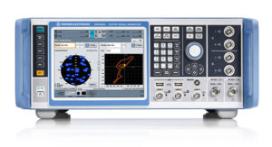
Designed to generate highly realistic test scenarios, Rohde & Schwarz signal generators like the R&S SMW200A and the R&S SMBV100B offer a unique approach to generating complex and highly realistic scenarios for testing of GNSS receivers that are able to work with diverse navigational systems such as GPS, GLONASS, Galileo, BeiDou and QZSS/SBAS signals. The R&S SMW200A and the R&S SMBV100B can emulate them all for testing.
R&S SMW200A
The R&S SMW200A GNSS simulator (pictured above) can be used to produce complex interference scenarios with multiple interferers — all generated within the instrument itself. It can emulate up to 144 GNSS channels and can be equipped with up to four RF outputs. With its ability to simulate multi-constellation, multi-frequency, multi-antenna and multi-vehicle scenarios, the R&S SMW200A is able to cover a variety of high-end GNSS applications.
R&S SMBV100B
The R&S SMBV100B supports the same navigational systems, with access to 24 GNSS channels and one RF output, with the same ability to configure realistic scenarios including obscuration, multipath and atmospheric effects, as well as the specific characteristics of the antenna and the simulated vehicle. An integrated noise and CW interference generator can also be added.
Since the devices do not require an external PC for scenario configuration, all the tests can be created quickly through the user-friendly GUI. Due to all-encompassing instrument options available, both simulators can be set up to fit unique user requirements.
For testing GNSS receivers under controlled and repeatable conditions, the R&S SMW200A and the R&S SMBV100B provide extensive and cost-effective solutions. The platforms are ready to adapt to future requirements and testing of newly implemented GNSS signals.
SDX is a proven and advanced GNSS simulator based on GPU-accelerated computing and software-defined radio (SDR).
It is available as a complete turnkey system suitable for all GNSS simulation needs, including everything from compact test benches to complete CRPA test systems, such as SDX wavefront and SDX anechoic. Moreover, its software-defined roots enable the selection of cost-effective hardware into configurations that can be repurposed for different projects.
The architecture behind SDX provides real-time simulation of uncompromising accuracy. It features advanced signal customization and supports configurable outputs. IQ data can be generated in, or imported back into, the simulator as well. The API is embedded in the simulator core, enabling deep automation with a few simple clicks, as well as complex scripts developed with popular programming languages.
SDX simulates multiple constellations on multiple frequencies (GPS, Galileo, GLONASS, BeiDou and SBAS) on a large number of channels. Encrypted codes are supported for GPS and Galileo.
The Advanced Jammer module in SDX gives users complete control over interference creation. It is integrated directly into simulation scenarios to enable dynamic jammers (up to 120dB J/S) to interact with GNSS signals.
SDX also allows users to create advanced scenarios suitable for any type of vehicle: antenna patterns (receiver and GNSS SV), LEO/GEO/HEO orbits, multipath, hardware-in-the-loop (HIL), additive pseudorange errors, message modification and corruption, raw logging and more.
It is suitable for the design and validation of GNSS receivers, complex integration, academic research, NAVWAR and test engineering.
SDX is developed and actively supported by Skydel’s engineering teams and worldwide distributors. Skydel offers direct support to clients to ensure prompt deployment and integration, or to review advanced customization requirements.
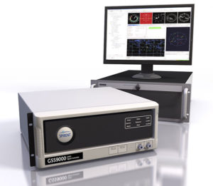
GSS9000, SIMMNSA, CRPA Test System, anechoic chamber testing, mid-range testing
Photo: Spirent
Spirent Federal provides GPS/GNSS test equipment that covers all applications, including research and development, integration/verification, and production testing.
GSS9000. The Spirent GSS9000 Multi-Frequency, Multi-GNSS RF Constellation Simulator is Spirent’s most comprehensive simulation solution. It can simulate signals from all GNSS and regional navigation systems and has a system iteration rate (SIR) of 1000 Hz (1 ms), enabling higher dynamic simulations with more accuracy and fidelity. The GSS9000 supports restricted/classified signals. Users can evaluate the resilience of navigation systems to interference and spoofing attacks, and have the flexibility to reconfigure constellations, channels, and frequencies between test runs or test cases.
SimMNSA. SimMNSA allows authorized users to simulate true M-code for the first time ever. SimMNSA has been successfully delivered to users of the GSS9000 series simulator. SimMNSA has been granted Security Approval by the Global Positioning System Directorate.
CRPA Test System. Spirent’s Controlled Reception Pattern Antenna (CRPA) Test System generates both GNSS and interference signals. Users can control multiple antenna elements. Null-steering and space/time adaptive CRPA testing are both supported by this comprehensive approach.
Anechoic Chamber Testing. Spirent’s GSS9790 Multi-Output, Multi-GNSS RF Constellation Wave-Front Simulator System is a development of the GSS9000. The GSS9790 is a unique solution providing the core element for GNSS applications that require a test system that can be used in both conducted (lab) and radiated (chamber) conditions.
Mid-Range Solutions. Spirent also offers solutions that cater to intermediate GPS/GNSS testing needs. The GSS7000 multi-constellation simulator provides an easy-to-use solution for GNSS testing that can grow with users’ requirements. The GSS6450 RF record & playback system enables replay of a real-world GNSS/GPS test repeatedly in the lab.
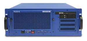
A scalable software-defined simulation platform powered by Skydel’s SDX, capable of generating high-fidelity GNSS and jamming signals simultaneously across multiple constellations and vehicles. Simultaneously simulate every signal below:
BroadSim’s software-defined platform includes intuitive user control and APIs; fast development cycles; flexible licensing and upgradability; and no additional hardware needed to maintain.
Forms
Original (4U)
Rack-mounted 4U simulator used for lab or field testing
4 RF outputs (unlimited jamming signals generated on 1)
1000-Hz simulation iteration rate
High-performance processor, GPUs and memory
Anechoic
Simulation system used for anechoic chamber testing
32 RF outputs and 16 dual-frequency antennas
Automatic antenna mapping
Automatic time delay and power loss calibration
Wavefront
Phase coherent simulation system
Real-time automated phase calibration
Scalable from 4 to 16 elements
Supports CRPA and multi-element receiver testing
Supports jamming and spoofing
Panacea
An automated PNT performance and vulnerability test suite that supports up to 32 UUTs (units under test) in real time, from test plan creation to post-test evaluation.
Time synchronization to live sky
Compatible with 100+ different GNSS receiver brands
Create dynamic scenarios with parameters such as jamming patterns, motions, power loss, delays and more.
Manages receiver communication and standardizes data output for easy analysis, visualization and reporting
The GEO-FOG 3D Dual inertial navigation system (INS) is designed for applications that require heading at system startup or in low dynamic conditions. (Image: KVH)
KVH Industries will showcase its inertial products at Ocean Business 2019, taking place in Southampton, U.K., April 9-11.
When GNSS is not an option, KVH’s Fiber Optic Gyro (FOG)-based IMUs and inertial navigation systems — the GEO-FOG 3D and 3D Dual — provide accurate and reliable navigation for manned and unmanned maritime and underwater systems, the company said.
“When we compare the data and performance of the KVH 1750 IMU to comparable SWAPC components, we find a tremendous disparity in performance,” said Ben Kinnaman, CEO of Greensea Systems Inc. “The KVH 1750 IMU outperforms similar components and sensors in that category by orders of magnitude.”
Visit KVH at Stand J8 and learn more about KVH’s FOG-based 1750 IMU, which is available with 2g accelerometers and designed specifically for subsea vehicle navigation and positioning.