Uber has made big moves implementing location technology by signing a deal with TomTom, buying Microsoft’s mapping technology, and outright purchasing deCarta this year. The company is working with Carnegie Mellon University in Pittsburg to develop autonomous vehicle technology. In other location news, distinct technology is cropping up in the indoor location market to make widespread implementation possible.
Kevin Dennehy
Uber is becoming a big player in the location industry with its announcement this month that it will use TomTom’s maps and traffic data for its ride-hailing service. The deal’s financial terms were not disclosed.
While Uber unsuccessfully made a $3 billion bid for Nokia’s mapping business, it also acquired Microsoft’s mapping technology and the key personnel that came with it. The San Francisco-based company, currently operating in 300 cities worldwide, also acquired veteran location industry deCarta earlier this year.
The mapping data will be key in Uber’s strategy to be a major force in autonomous vehicle development. To research driverless cars, Uber has leased a 53,000-square-foot facility in Pittsburgh.
The question is, what market segment will be first for major autonomous vehicle rollout? At least one executive believes such technology companies as Uber have the advantage. “Because the continued success of [Uber’s] business depends on it, and they have the money to spend on it to gain a competitive advantage,” explained Scott Frank, Airbiquity vice president of marketing. “If ride share companies can reduce the variability and expense of physical drivers, they can reduce the cost of their services — even while improving their margins, and compete more effectively for market share versus private ride services, like taxis/limousines and public transportation, which is more limiting in terms of availability and comfort.”
Frank says his company sees the market differently than others when it comes to autonomous vehicle development and rollout. “Google has been clear since the beginning about their automotive end goal, which takes a very long-range view — produce fully autonomous vehicles connected to public infrastructure with everything connected by Android and enabled by Google computing, data management, service delivery and advertising capability,” he said.
Apple and Tesla’s ambitions are more in close and short-term, in that they want to produce electric vehicles that are better than what the traditional automakers are able to churn out, Frank said.
“Uber is a recent entry into the fray, so it’s a bit premature to put them in the ‘build a vehicle platform’ class, although it’s becoming evident that they are very interested in developing underlying technologies that autonomous cars will certainly rely on,” he said. “In the last couple of months we’ve seen public statements from large traditional automakers referencing their autonomous vehicle ambitions, so they are definitely going to step up and not simply concede the autonomous opportunity to Google — or any another automotive industry newcomers.”
Frank believes there are distinct areas in the United States where autonomous vehicle rollouts make sense. “[Companies are looking at] transportation pain points that autonomous will solve like urban traffic and lack of easy and affordable parking, public transportation infrastructure that can more easily accommodate the necessary changes to integrate and support autonomous, and metro sizes that aren’t so large that it would impossible and/or too costly to get anything done,” he said. “So cities like Portland, Minneapolis, Austin, Raleigh and [such areas as] Silicon Valley come to mind, to name just a few.”
Either way, autonomous vehicles will present huge societal and business changes and such questions as will the public trust the new technology and get them where they need to go, safely and reliably, Frank said. “As with all new technologies there will be an adoption curve at play here with early adaptors taking the lead ahead of the mainstream,” he said. “We saw the same thing with horseless carriages, by the way. People placed more trust in their horses before they began to understand and allow themselves to realize the benefits of motorized transportation.”
In other autonomous vehicle news, Ford said last week it was ramping up its driverless car efforts by being the first automaker to test its self-driving cars at Mcity, a 32-acre prototype town with private roads in Ann Arbor, Mich.
Indoor Location Market Finds Low-Cost Technology
Recent advancements in chip-based indoor location position technology are allowing developers to find a low-cost way to get the capability into multiple devices, said Bruce Krulwich, Grizzly Analytics founder.
“The most exciting aspect of recent advances in chip-based indoor location positioning technologies is that indoor positioning is being added to the next generations of chipsets already being used in today’s smartphones,” said Krulwich, who recently released a new study, Chip-Based Indoor Location Technologies, which profiles GPS, Wi-Fi and sensor processing chips. “This means that the chips that device makers already include in their designs will soon include indoor location capabilities.”
The biggest advantage of chip-based approaches is that they can integrate data from GPS, Wi-Fi and MEMS motion sensors at a very low level, using data direct from the chips, without requiring work by the CPU to enable more efficient and continuous location positioning, Krulwich said.
“While there are many approaches being taken by the chip makers, the one that I’m most excited about is the combination of motion sensing with GPS. In this approach, the same chips that process GPS signals also use data from MEMS sensors, such as accelerometers, gyroscopes and magnetometers, to track locations when GPS signals are unavailable,” he said. “Motion-sensing approaches don’t work forever, since errors in the sensors accumulate over time, but should be able to give reasonable location estimates for 10-15 minutes after a person walks inside. This should be long enough to be a very valuable source of location positioning in between GPS or Wi-Fi signals.
Krulwich said this positioning approach can work anywhere, without Wi-Fi hotspots, BLE beacons or even maps of the site. “This is the closest to ubiquitous location positioning that I’ve seen,” he said.
Krulwich believes the new chip technology will allow the first large-scale incorporation of location technologies into electronic devices, appliances, wearables, Internet of Things (IoT) and others. “A cool example is a camera that tracks an athlete’s location automatically as they run around the basketball court.”
In other location news:
A new agenda is out for Driverless, which will be March 22-23, 2016, at the Crowne Plaza Hotel, San Francisco Airport. The autonomous vehicle conference will feature more than 30 speakers and 15 exhibitors. Go to www.driverlessmarket.com for more information.
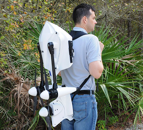
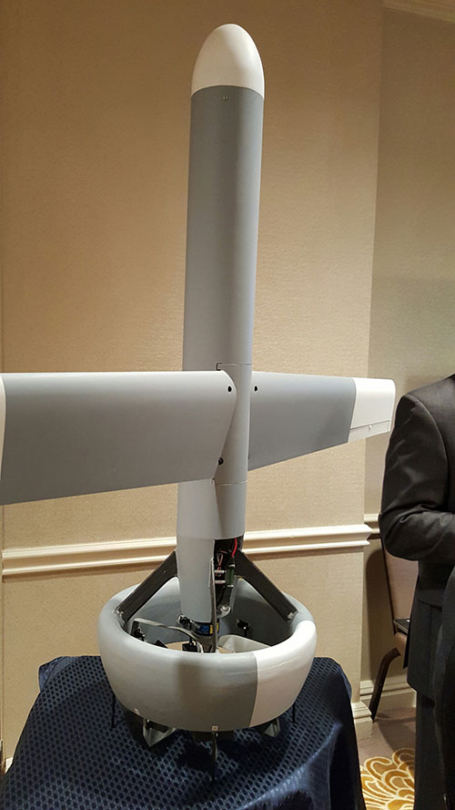
The Bullray UAS is a fully autonomous, amphibious, man-portable tricopter/quadcopter that makes vertical take-offs and landings.
Rated IP-67, the rugged design is capable of performing in all weather conditions and doesn’t require a transit case. It can carry a significant sensor payload: GPS, FLIR cameras, lidar, metal detection systems and more.
Rapid Composites — builder of high-end UAVs for the military and first responders — custom manufactures the units. The company won the UAV category in the 2015 JEC Innovation Awards.
The Federal Aviation Administration (FAA) wants unmanned aircraft owners to know that there’s no need to work with a “drone registration” company to help them file an application for a registration number.
Owners should wait until additional details about the forthcoming drone registration system are announced later this month before paying anyone to do the work for them.
The Task Force assigned to provide FAA Administrator Michael Huerta with recommendations on the registration process is still days away from delivering this information. But at least one company is already offering to help people register their drones — for a fee.
Speaking to the Task Force two weeks ago, Administrator Huerta told the group to provide guidance on a streamlined unmanned aircraft registration process that will be simple and easy to complete, and which types of UAS would need to be registered and which would not. The Task Force agreed and is working on recommendations for a system that is similar to registering any newly purchased product with its manufacturer, as well as a minimum weight for unmanned aircraft that must be registered.
Drone owners should visit FAA.gov for official updates on the unmanned aircraft registry.
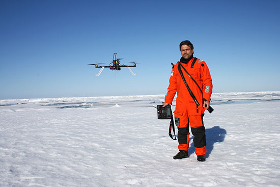
Researchers conducted an autonomous multicopter flight in the Arctic with its own test UAV platform that used a u-blox LEA-M8T GPS receiver. (Photo: Alfred-Wegener Institute)
How do you successfully pilot a UAV in the remote expanses of the Arctic Ocean when the compass can’t provide reliable positioning data? Engineers on board the Alfred Wegener Institute’s (AWI’s) research icebreaker Polarstern specially programmed a multicopter, allowing it to navigate despite the deviations produced by the Earth’s magnetic field near the North Pole. The researchers recently celebrated the copter’s first successful autonomous flight and landing on an ice floe.
“At high latitudes, autonomous navigation is a major challenge,” said Sascha Lehmenhecker, an engineer at AWI. “Navigation systems normally use magnetic sensors. But near the poles, the lines of the Earth’s magnetic field are nearly perpendicular to the ground, making precise navigation extremely difficult. That’s why commercial multicopter control systems aren’t well suited for use in polar regions.”
Ice Floe Landings
Lehmenhecker’s team refined the control systems for multicopters to land on ice floes and fly back to their “mother ship” autonomously several hours later. The particular task: both the ice floe and the ship are in motion. The ship has to continue on its scheduled course to conduct other research, while wind, waves and currents cause the ice floe to drift. It’s precisely the direction and speed with which it drifts that the multicopter needs to determine.
The team pursued two approaches. “In the first approach, the multicopter remains in constant contact with a receiving station, which uses the copter’s GPS data to calculate the discrepancies. In other words, the multicopter transmits its GPS position to the station, which in turn transmits back the corresponding, adjusted coordinates,” explained Lehmenhecker. “The second option: We use two onboard GPS receivers to calculate the actual change in the copter’s position. Though this is the better method, it’s also much more complex, and we’re still just starting to develop it.”
The system passed its first test, conducted on an ice floe in the arctic Fram Strait (79° N parallel). In the test, the team and copter were left on a floe, clear of magnetic interference produced by electric motors on board the Polarstern. The team manually flew the copter 3 kilometers out, to the edge of visual range, then activated the autonomous return program. The multicopter flew to the preset coordinates and safely landed on its own.
Underwater Assist
Lehmenhecker’s team came up with the idea for this development in connection with the use of sensitive devices under the ice, such as the torpedo-shaped autonomous underwater vehicle (AUV) Paul, which explores the ocean beneath the sea ice. “To optimally plan its dives, it’s important to have precise information on the movement of the sea ice,” Lehmenhecker said. Conventionally, this was achieved by deploying ice trackers on floes with the help of a Zodiac boat or helicopter — a difficult and time-consuming method. Further, the researchers generally try to avoid leaving the safety of the Polarstern wherever possible — jagged ice floes and polar bears present additional risks.
During 2012, the group first used a UAV to assist Paul. The UAV landed on the ice via remote control, then used GPS to determine its position and transmit the data back to the research ship, which was monitoring Paul’s dive. In this way, the multicopter took on an important role, offering navigational support for the AUV. Once each dive was complete, the ship had to return close to the multicopter’s position so the pilot could remotely guide it back to the ship, which was only possible in visual range.
Now, the new developments “will expand the service radius of our copters from visual range to as much as 10 kilometers,” Lehmenhecker said.
Four point clouds, nonregistered, of georeferenced images from four UAV flights.
By Christian Eling, Lasse Klingbeil, Markus Wieland, Erik Heinz and Heiner Kuhlmann
Direct georeferencing with onboard sensors is less time-consuming for data processing than indirect georeferencing using ground control points, and can supply real-time navigation capability to a UAV. This is very useful for surveying, precision farming or infrastructure inspection. An onboard system for position and attitude determination of lightweight UAVs weighs 240 grams and produces position accuracies better than 5 centimeters and attitude accuracies better than 1 degree.
Data acquisition from mobile platforms has become established in many applications recently, particularly using unmanned aerial systems (UASs). Unlike other mobile platforms, unmanned aerial vehicles (UAVs) can overfly inaccessible and also dangerous areas. Furthermore, they can get very close to objects to collect high-resolution data with low-resolution sensors, and they enable approach from all viewing directions without physical contact. UAVs now see use in precision farming for phenotyping or plant monitoring, and in infrastructure inspection and surveying.
Data acquisition from mobile platforms has become established in many applications recently, particularly using unmanned aerial systems (UASs). Unlike other mobile platforms, unmanned aerial vehicles (UAVs) can overfly inaccessible and also dangerous areas. Furthermore, they can get very close to objects to collect high-resolution data with low-resolution sensors, and they enable approach from all viewing directions without physical contact. UAVs now see use in precision farming for phenotyping or plant monitoring, and in infrastructure inspection and surveying.
This article addresses lightweight UAV use for mobile mapping and uses the term micro aerial vehicle (MAV) throughout. MAVs can generally be characterized as having a weight limit of 5 kilograms and a size limit of 1.5 meters.
We focus on the development of a real-time capable, direct georeferencing system for MAVs, since spatial and time restrictions often exclude the possibility of deploying ground control points for an indirect georeferencing. The demand for the real-time capability results from the aim to also use the georeferencing for autonomous navigation of the MAV and to enable a precise time synchronization of the onboard sensors. Furthermore, a real-time direct georeferencing also offers the opportunity to process collected mapping data during flight.
Mapping on demand. The goal of this research project, funded by the Deutsche Forschungsgemeinschaft (DFG), is to develop an MAV that can identify and measure inaccessible three-dimensional objects by use of visual information. A major challenge within this project comes with the term “on demand.” This means that apart from the classical mapping part, where 3D information is extracted from aerial images, the MAV is intended to fly fully autonomously on the basis of a high-level user inquiry. During the flight, obstacles must be detected and avoided. To extract semantic information that can be used to refine the trajectory planning, the mapping data has to be processed in real time. When the georeferencing information is used as initial values for the bundle adjustment, the image processing can be significantly accelerated.
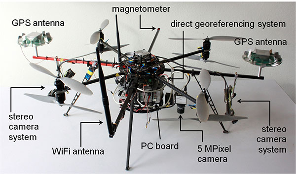
Figure 1 shows the current MAV platform developed in this project. We customized an MAV kit to a coaxial rotor configuration, replaced the centerplates with more stable carbon-fibre plates to stabilize the system, and installed the direct georeferencing and the mapping sensors. The two stereo camera pairs, pointing forward and backward, act as an additional sensory input for the position and attitude determination; the 5M-pixel industrial camera with global shutter is the actual mapping sensor. The PC board is used for onboard image processing, flight planning and machine control; the Wi-Fi module enables a connection to a ground station.
Figure 1. The MAV with mapping and georeferencing sensors, developed for the research project Mapping on Demand.
Although the direct georeferencing system must be small and lightweight, accuracy requirements for its position and attitude determination are high. Generally, these accuracy requirements are different for the machine control, navigation and mapping purposes.
In our project, the MAV is intended to maintain a safety distance of about 0.5 meter to obstacles. Hence, a position accuracy of 0.1 meter is sufficient for the navigation. The absolute attitude accuracy should be in the range of 1 to 5 degrees. For machine control, relative information is more important, and for this the accuracies should be slightly higher.
For mapping purposes, the positions and attitudes have to be known better, since the absolute georeference of the final product (for example, a high-resolution 3D model of a building) is based on the positions and attitudes from the direct georeferencing system. Therefore, the position accuracy should be in the range of 1–3 cm and the attitude accuracy should be better than 1 degree. The relative accuracy of the exterior camera orientation can be improved by a photogrammetric bundle adjustment, but systematic georeferencing errors should be avoided.
To summarize:
The weight of the system has to be less than 500 grams (g), to be applicable on MAVs.
Especially for the control and navigation, the system has to be real-time capable.
All sensors have to be synchronized and outages of single sensors should be bridgeable by other sensors.
The system is intended to provide accurate positions (σpos < 5 cm) and attitudes (σatt < 1 deg) during flights.
The integration of data from additional sensors, such as cameras, should be possible.
The ability to include additional sensors to the system was, apart from the size and the weight constraint, the main reason for developing a proprietary system instead of using a commercial unit with similar capabilities.
Direct Georefencing
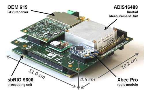
The current version of the system weighs 240 g without GPS antennas (see figure 2). To reduce weight, the antennas were dismantled, reducing their weight from 350 g to 100 g. However, since the antenna reference point got lost in this process, the antennas had to be recalibrated in an anechoic chamber for further use. By comparison to the original antennas, the dismantling led to significant changes in the phase center offsets (circa 4 cm in the Up, < 1 mm in the North and East component) and in the phase center variations (< 5 mm) of the antennas.
Figure 2. The direct georeferencing system.
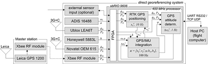
Figure 3 shows a flow chart of the direct georeferencing system with the sensors and the main calculation steps. The system consists of a dual-frequency GPS receiver, a single-frequency GPS receiver, an inertial measurement unit (IMU) and a magnetometer. The dual-frequency receiver is the main positioning device. Together with the GPS raw data from the master station (carrier phases ϕM, pseudoranges PM), which is transmitted via a radio module, the data of the dual-frequency receiver (ϕR, PR) is used for an RTK positioning, leading to centimeter position accuracies.
Figure 3. Flowchart of the direct georeferencing system.
In collaboration with the data of the single-frequency receiver (ϕB, PB), the data of the dual-frequency receiver is also used for GPS attitude determination. The corresponding GPS antennas of these two receivers form a short baseline (baseline length = 92 cm) on the MAV. The determination of the baseline vector in an e-frame (Earth-fixed) enables yaw and the pitch-angle determination.
The tactical-grade micro-electro-mechanical (MEMS) IMU, which includes three-axes gyroscopes, accelerometers and magnetometers, provides angular rates (ω), accelerations (a) and magnetic field observations (h) with high rates (100 Hz) for position and attitude determination. To be unaffected by the electric currents as much as possible, an additional magnetometer is placed on the outer end of one of the rotor-free MAV arms.
The direct georeferencing system further consists of a processing unit, which is a reconfigurable IO board, including a field programmable gate array (FPGA) and a 400-MHz processor. In this combination, the FPGA is used for fast parallel communication with the sensors. Afterwards, the preprocessed sensor data are provided to the 400-MHz processor via direct memory accesses, avoiding delays and supporting the system’s real-time capabilities. Finally, the actual position and attitude determination is carried out on the 400-MHz processor.
Methodologies
All position and attitude determination algorithms running on the system were developed in-house. Generally, the integration of these steps could be realized in one tightly coupled approach. Nevertheless, in the current implementation, we decided to separate the different raw data calculation steps, and we only use interactions at the level of parameters. This approach has the advantage that the integration is more reliable and more practical in the real-time programming.
GPS/IMU integration. In this calculation step, all available sensory input is fused to determine the best position and attitude of the system that is currently available. The GPS and the IMU measurements complement each other well, since the IMU provides short-term stable high-rate (100 Hz) data, and the GPS provides long-term stable low-rate (10 Hz) data.
The GPS/IMU integration can be separated into the strapdown algorithm (SDA) and the Kalman filter update. In the SDA, the high-dynamic movement of the system is determined integrating the angular rates and the accelerations of the MEMS IMU in real time. Because the SDA drifts over time, the long-term stable measurements of the magnetometer and the GPS receivers are needed to correct and bound the drift of the inertial sensor integration, which is realized in an error state Kalman filter.
In the GPS/IMU integration algorithms, the navigation equations of the body frame (b-frame) are expressed in an e-frame. Therefore, the full state vector x includes the position xep and the velocity vep, represented in the e-frame. For the attitude representation a quaternion q is used. Finally, the accelerometer bias bba and the gyro bias bbω are also estimated:
The observations in the measurement model are:
the RTK GPS position xea of the dual-frequency RTK GPS antenna reference point, expressed in the e-frame,
the GPS attitude baseline vector Δxeb, expressed in the e-frame,
the magnetic field vector hb, expressed in the b-frame.
Because the reference point of the RTK GPS antenna is not identical to the system reference point, a lever arm between the system and the antenna reference point must be regarded in the measurement model of the RTK GPS positions. From calibration measurements, the coordinates of the lever arm are precisely known in the b-frame.
In the SDA, a coupling between the accelerations, measured by the IMU, and the positions, measured by the RTK GPS, exists. Due to this coupling the yaw angle can be observed, but only in the presence of horizontal accelerations.
To determine an accurate and reliable yaw angle for every motion behavior, the short GPS baseline is realized on the MAV. A significant challenge in processing this baseline is the ambiguity resolution, because only single-frequency GPS observations can be used. Empirical tests have shown that the ambiguity resolution of a single-frequency GPS baseline generally takes several minutes. Among other strategies, we use the additional information from a magnetometer to improve the ambiguity resolution and to actually enable an instantaneous ambiguity fixing during kinematic applications.
Ferromagnetic material on the UAV and high electric currents of the rotors create significant disturbances of the magnetometer during flight. While the influence of the material can be compensated by calibration procedures, the influence of the dynamically changing electric currents are more challenging. To minimize them, the magnetometer is placed at the outer end of a rotor-free arm of the MAV. Also, the measurement model is arranged so that magnetic field observations only have an impact on the yaw determination in our algorithms.
RTK GPS Positioning. RTK GPS positions are calculated in real time with a rate of 10 Hz. These RTK algorithms are in-house developed, although commercial and open-source solutions are available. The main reasons for developing custom software are the following:
Integration of other sensors and/or solutions is possible, to improve ambiguity resolution and cycle-slip detection.
In commercial software, there is generally no access to the source code.
In the development of a real-time capable system, the software must meet the requirements of the operating system running on the real-time processing unit.
Generally, the RTK GPS algorithm complies with a single baseline determination (one master, one rover), where the master station remains ground-stationary and the rover is onboard the MAV.
To resolve the ambiguities and finally to determine the RTK GPS positions, the parameter estimation is performed in three steps: float solution, integer ambiguity estimation and fixed solution.
The float solution is realized in an extended Kalman filter (EKF). Beside the rover position, represented in the e-frame, the EKF state vector xSD also contains single-difference (SD) ambiguities N j on the GPS L1 and the GPS L2 frequencies. The reason for estimating SD instead of double-difference (DD) ambiguities is to avoid the hand-over problem that would arise for DD ambiguities, when the reference satellite changes.
To allow for an instantaneous ambiguity resolution, the observation vector l consists of DD carrier phases Φjkrm and DD pseudoranges Pjkrm on the GPS L1 and the GPS L2 frequencies.
In the current implementation, a random walk model is assumed as a dynamic model of the MAV in the EKF. Even if this is a simple model, it complies with the movement of the vehicle, when the process noise is chosen appropriately.
The float solution procedure provides real-valued ambiguities and their covariance matrix. These ambiguities now must be fixed to correct integer values, to fully exploit the high accuracy of the carrier phase observables. We applied the MLAMBDA method for integer ambiguity estimation.
Finally, a decision must be made whether or not the result of the integer ambiguity estimation can be accepted. This is done by the simple ratio test. With the ambiguities fixed, the final rover position xae is estimated with cm accuracies.
Usually, the time to fix the ambiguities with the algorithm takes a few epochs, but often the ambiguities can be fixed instantaneously. Once ambiguity resolution has been successful, the ambiguities can be held fixed, as long as no cycle slip or loss of lock of GPS signals occur.
Due to the GPS/IMU integration, we have a precise prediction of the RTK GPS positions between two epochs. Thus, the integration of the inertial sensor readings enables us to detect and also repair cycle slips very reliably.
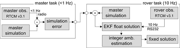
The observations of the master receiver must be transmitted via radio to the direct georeferencing system. In practice, this data transmission can only be realized with a rate of 1 Hz. To be less dependent on this potentially unreliable master data transmission and the lower sampling rate, simulated master observations are used for RTK GPS position determination. Hence, in the actual processing, the true master observations are only used to update the simulation errors in the master task (figure 4), which have to be applied to correct the simulation results in the rover task.
Figure 4. Task scheduling of the RTK GPS algorithms.
GPS attitude determination. The GPS baseline is determined at 1 Hz. In contrast to the RTK GPS positioning, both antennas of the attitude baseline are mounted on the MAV, so that the complete baseline is moving. Furthermore, the baseline length is constant and known from calibration measurements. The GPS attitude determination also consists of the three steps: float solution, integer ambiguity estimation and fixed solution.
The float solution is also based on an EKF where the single-frequency SD ambiguities N j of the attitude baseline are estimated. Further parameters in the state vector are the baseline parameters and the first deviation of the baseline parameters.
As observations DD carrier phases ΦjkAB and DD pseudoranges PjkAB on the GPS L1 frequency are used. To improve the ambiguity resolution, the attitude from the GPS/IMU integration is added to the observation vector, by transforming the known b-frame baseline parameters into the e-frame. Finally, also the known baseline length can be added as a constraint to the observation vector.
In the integer ambiguity estimation, we apply the MLAMBDA method again. Due to the prior information about the attitude of the baseline, the float ambiguities can already be estimated with high accuracies in the float solution. If the ambiguities could not be fixed with the MLAMBDA method, we consider the 10 best solutions for further processing. Unreliable ambiguity parameters are eliminated in a random order, and the MLAMBDA method is applied again. Afterwards we use the ambiguity function method and the known baseline length to exclude false candidates of the 10 best solutions.
If only one solution remains, the ambiguities can be fixed to integer values. Tests have shown that this approach leads to an instantaneous ambiguity resolution success rate of about 95 percent.
Similar to the RTK GPS positioning, the IMU readings are also used to detect cycle slips for the attitude baseline determination, when the ambiguities have been fixed successfully. With ambiguities fixed, the baseline parameters can be determined with millimeter to centimeter accuracies. This leads to yaw angle accuracies in the range of 0.2–0.5 degrees, when the attitude baseline has a length of 92 cm.
Applications and Results
As mentioned, one goal of Mapping on Demand is 3D reconstruction from visual information. The opening image shows such results. During four flights. images were collected with a sampling rate of 1 Hz, and the position and the attitude of the camera was determined in real time using the direct georeferencing system. A bundle adjustment was processed using these positions and attitudes as initial values. Afterwards, dense point clouds could be generated from the oriented images using an open-source software package (PMVS). Due to georeferencing of the collected images, the point clouds are also georeferenced. The image shows results of four flights in one scene, to demonstrate consistency of the georeferencing.
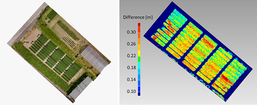
Agriculture. In figure 5, georeferenced images were taken during a flight over a wheat field. The same process was repeated after two weeks. The difference of the respective point clouds, which were determined using the software Photoscan by the company Agisoft, reveals the plant growth at an interval of two weeks. These results show that the determination of plant growth rates, which usually result from time-consuming field work, can be done easily and with high resolution using MAVs. With the use of a direct georeferencing system, this process becomes even more efficient because the deployment of ground control points can be omitted.
Figure 5. Orthophoto of a wheat field (left) and the difference of the vegetation height, determined from the results of two MAV flights at an interval of two weeks (right).
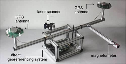
Portable laser scanning system. The small and lightweight design of the direct georeferencing system offers several other opportunities for various applications. One example is the use of the direct georeferencing system in combination with a small, lightweight and low-cost laser scanner.
Terrestrial laser scanning has become an established technology for 3D data acquisition in surveying and mapping because laser scanners provide high-resolution data with high accuracies at high speed. However, for measurement of a complex scene, the laser scanner generally has to be moved to different viewpoints, and all measured scenes have to be registered and georeferenced, a significant increased effort. In contrast, with a directly georeferenced kinematic laser scanning system, complex scenes can be measured with little effort.
Figure 6 shows a portable laser scanning system we developed for kinematic laser scanning. It combines the direct georeferencing system with a low-cost, lightweight 2D time-of-flight laser scanner. Time synchronization and the point cloud calculation are directly realized on this unit.
Figure 6. A directly georeferenced portable laser scanning system for kinematic 3D mapping.
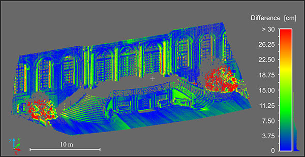
Figure 7 shows differences between a directly georeferenced point cloud, measured by the portable laser scanning system, and a terrestrial laser scanning point cloud, which was indirectly georeferenced using ground control points. Although there are some systematic errors visible, the differences are mostly less than 7.5 cm. The larger differences in the foreground (red) are a result of growing vegetation in the period between both scans. The systematic errors result from the system calibration between the laser scanner and the direct georeferencing system. We are working to improve these calibration methods.
Figure 7. Difference between the results of the directly georeferenced portable laser scanning system and the results of a terrestrial laser scan, which act as reference solution here.
Manufacturers
The MAV is based on a MikroKopter OktoXL assembly kit of HiSystems GmbH. It uses NavXperience 3G+C GPS antennas. The system consists of a dual-frequency NovAtel OEM 615 GPS receiver, a single-frequency u-blox LEA6T receiver, an Analog Devices ADIS 16488 IMU, a Honeywell HMC5883L magnetometer, an XBee Pro 868 radio module, a National Instruments sbRIO 9606 processing unit and a Hokuyo UTM30LXEW 2D time-of-flight laser scanner.
Christian Eling holds an MSc degree in geodesy and is a scientific assistant at the Institute of Geodesy and Geoinformation (IGG) of the University of Bonn.
Lasse Klingbeil received his Ph.D. in experimental physics in 2006. He heads the GNSS and mobile multi-sensor systems group in the IGG. Markus Wieland is a graduade mechanical engineer responsible for the mechanical and electrical design and for the control and readout of various sensor systems at the IGG.
Erik Heinz received his MSc in geodesy and geoinformation from the University of Bonn. He is a Ph.D. student at the IGG. Heiner Kuhlman is a full professor at the IGG. He has worked extensively in engineering surveying, measurement techniques and calibration of geodetic instruments.
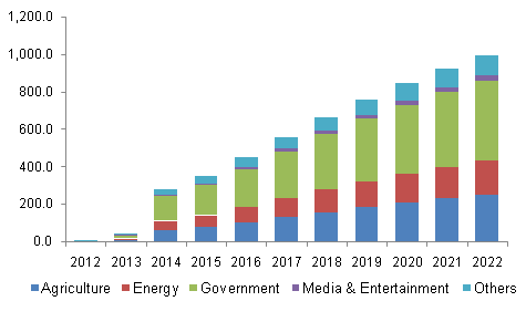
The global commercial UAV market is expected to reach $2.07 billion by 2022, according to a new study by Grand View Research Inc.
Increasing applications in agriculture and law enforcement are expected to drive commercial UAV industry growth over the forecast period. Commercial drones are finding applications across various industry verticals globally. Every industrialized country in the world is making investments in drones, thus driving the scope and technological developments for applications in the commercial UAV market.
Drones are contemporary alternatives for activities where human life cannot be risked. Such drones find applications in various industrial verticals including military, homeland security, retail and agriculture. The demand is significantly higher for military applications, although commercial applications are progressively catching up.
Aviation regulatory bodies such as the Federal Aviation Administration (FAA) have imposed restrictions on the use of such drones taking into consideration the difficulties in managing such huge air traffic and the safety of the citizens. However, the FAA is known to be undertaking an initiative to accelerate the UAV approval process for public safety agencies and broaden access to civilian organizations for a variety of commercial, industrial and other applications.
Further key findings from the report suggest:
Rotary blade drones accounted for more than 70 percent of the global market share owing to their easy maneuverability and compact design. Moreover, such single and multi-rotor drones equipped with rotary blades have Vertical Take-Off and Landing (VTOL) abilities for applications, where there is limitation of space for fixed blade drones to take off. The development of advanced hybrid UAVs that operate on non-conventional sources of energy and nano, small miniature drones serve multiple applications across various industry verticals.
Government applications dominated the global commercial UAV industry constituting more than 40 percent of the market share in 2014. Increasing applications in law enforcement, security and surveillance, R&D activities, infrastructure, disaster management, and environmental studies have led to an increased demand for such unmanned aerial vehicles from the concerned government agencies. Innovative applications across agricultural sector have made it the fastest growing application segment, which is projected to grow at a CAGR of more than 18 percent from 2015 to 2022. Special agricultural drones can take snapshots of fields and help in analyzing crops. In addition, fix winged drones can be used for applications such as watering, spreading seeds, fertilizers, and pesticides over large farm fields that drastically reduce the time required and increase the efficiency.
North America is expected to grow at a CAGR of more than 16 percent over the forecast period on account of concentration of major drone manufacturers and increasing applications in the commercial sectors in the region. Governments and technology giants across the world are striving hard to provide internet to the people as a basic necessity. Facebook Inc. recently acquired Ascenta, a drone manufacturer for its pilot project to provide internet in remote areas using drones as movable wireless access points. Relaxation in regulations and increasing use of drones in law enforcement activities in Europe have led to the regional industry growth.
Major industry participants include AeroVironment Inc., BAE Systems, DJI, Elbit Systems, Parrot SA, Israel Aerospace Industries, The Boeing Company, and Textron Inc. Manufacturers resort to mergers and acquisitions as their key growth strategy to make their presence felt in the industry. Augmented funding, technological collaborations, and government agencies are expected to emerge as critical success factors for industry growth.
Grand View Research has segmented the global commercial UAV market on the basis of product, application, and region:
Commercial UAV Product Outlook (revenue, USD billion, 2012-2022)
Fixed wing
Rotary blade
Nano
Hybrid
Commercial UAV Application Outlook (revenue, USD billion, 2012-2022)
Agriculture
Energy
Government
Media & Entertainment
Others
Commercial UAV Regional Outlook (revenue, USD billion, 2012-2022)
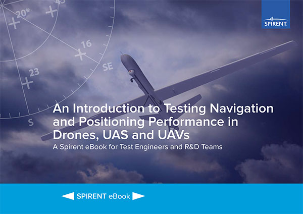
According to Spirent, “The use of unmanned aerial vehicles (UAVs) is starting to take off in commercial and military sectors. The potential applications of UAVs are many – including survey, mapping, media reporting, delivery, reconnaissance, conservation and search & rescue. What’s more, in some cases the cost of using UAVs has been found to be up to 98.8% cheaper than manned aircraft.
“But it is still early days, and for designers and developers of UAVs, there are many challenges in bringing viable models to market and putting them to work.”
The ebook looks at those challenges and sets out the main positioning and navigation considerations that UAV test teams should incorporate into their test regime, Spirent said. It covers:
GNSS/GPS performance considerations — how to evaluate positioning capabilities of UAVs
UAV design considerations, including where GNSS receivers should be placed, the type of antenna needed and more
Which environmental/external factors need to be considered, such as wind, temperature and multipath effects
At Unmanned Systems Defense, warfighters had the opportunity to learn about new technologies from government contractors and see demos in the exhibition hall. (PRNewsFoto/AUVSI)
ARLINGTON, Va. — Despite shrinking defense budgets, existing and emerging worldwide threats will make robotic and autonomous systems’ development important for decades, said officials at the Unmanned Systems Defense 2015 conference held here Oct. 27-29.
Because America has been at war for more than 14 years, unmanned technology has been developing at a rapid rate, perhaps even faster than emerging autonomous commercial systems. The replacement of even manned aircraft has some in the military establishment wary, but others know it’s only a matter of time before most vehicles, surface ships and aircraft are unmanned.
Navy Secretary Ray Mabus said that the F-35, which has been controversial because of its cost and capabilities, may be the last manned fighter aircraft.
Mabus acknowledged the rise in autonomous vehicles not only in the military, but in the civilian world. “Our grandchildren may never have to drive a car. I can’t wait for driverless cars,” he said.
The Navy is so high on unmanned systems that it recently named retired Marine Brig. Gen. Frank Kelley as deputy assistant secretary of the Navy for unmanned systems.
Like the other services, the Navy is experimenting with aviation systems that are inexpensive and small. It is developing swarming drones that are designed to overwhelm a target. Mabus said one of the cool drones that the Navy is developing is called Kraken, which operates underwater, then explodes past the surface to operate in the air.
A V-Bat UAV from Martin UAV. Applications include aerial mapping, border patrol, shipboard operations and others.
The Air Force also is developing small drones that can be launched and recovered by a larger aircraft after a mission is complete.
While the meeting was filled with government bureaucrats with the requisite PowerPoint slides detailing how long programs will take, they did say that the services are plowing ahead with autonomous technology that many of their civilian counterparts say are decades away.
Convoy Operations
An Army initiative called Leader Follower includes rudimentary autonomous convoy operations capability with GPS and base mapping systems, autonomous steering and braking. Army program managers say the program is in staffing, but should be approved in a few months.
The follow on to Leader Follower is a full-blown Automated Convoy Operations capability that would allow any manned system, including tanks and mobile artillery, to operate autonomously. Automated Convoy Operations are at least two-to-three years behind the Leader Follower program, Army officials said.
Other Army programs include route clearance systems to defeat underground improvised explosive devices and caches and mine rollers.
With all the new autonomous technology, at least one speaker said the first question should be why an unmanned system is needed at all, given its high cost and long lead times for rollout. “Does the technology enable a [service member] to fight better, or does it just get in the way?” said Lt. Col. Hank Lutz, U.S. Marine Corps joint staff.
Plans to Replace Aging Unmanned Systems
Lt. Gen. Michael Williamson, U.S. Army deputy to the assistant secretary of defense for acquisition, said the service is divesting its aging robotics and drone systems, which means future contracts for defense companies. “In 14 years of war, we have rode this equipment pretty hard,” he said. “We believe in modernization, but also looking to buy new systems, which is a new shift in order to gain a competitive advantage over our enemies, who are leveraging unmanned systems.”
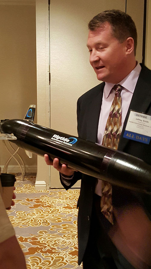
Jeff Smith, president and CEO of Riptide Autonomous Solutions, holds an unmanned undersea vehicle that has GPS sensors and antenna.
The big mantra from the military program managers and senior officials is having an “open architecture” that includes a control segment that works with both manned and unmanned systems. Williamson also echoed the need for standardization, but went further by saying the services should have a list of standards and one place, a facility, to ensure components actually work together.
While the “we want an open architecture” theme was in virtually every speaker’s presentation, one said that there needs to be a balance between the time a product is ready and its interoperability. “The Taliban’s [Program Objective Memorandum] cycle is a lot shorter. Don’t tell me that [your product] is plug and play,” said John Coglianese, U.S. Special Operations Command director, unmanned aerial systems.
DoD Reaches Out to Smaller Businesses, Silicon Valley
Realizing a need to assess new technologies and partner with innovative companies, the Defense Department recently established the Defense Innovation Unit, which is based in the San Francisco Bay area. The office is small with only a few personnel, said George Duchak, who was recently named director.
Duchak acknowledged that some companies suffer from government fatigue in that they see the same presentations over and over. By being out in the Silicon Valley, Duchak’s personnel can be more receptive and listen, rather than talk at companies. His office is made up of people who seek out new technology and vendors, serve as a conduit to local labs and assess companies who want work with the government, among other activities.
“We are kind of in a honeymoon period [with private companies]. It has been interesting finding companies where their patriotism aligns with whether or not they are going to make money,” Duchak said. “Google has been pretty receptive, not so much with Apple.”
Another group, the National Advanced Mobility Consortium, looks to match technology to defense needs for smaller companies looking to do business with the government. “We are trying to show how to engage nontraditional companies,” said Bill Thomasmeyer, National Advanced Mobility Consortium consultant. Thomasmeyer said it’s tough for a small company or individual entrepreneur to go through the complex government procurement cycle. “They are used to Silicon Valley, which has a 90-day cycle. The Federal Acquisition Regulation is 4,000 pages,” he said.
Currently, NAMC has 274 members, a third of which are not defense companies, Thomasmeyer said.
Future of GPS and Location Technology for Unmanned Systems
Virtually all unmanned systems, from drones to autonomous vehicles, use GPS location technology and advanced mapping. As systems evolve, and enemy threats become more sophisticated, new requirements are emerging.
“All of our systems use GPS, but we need to operate in a GPS-denied environment,” said Capt. Aaron Peters, U.S. Navy program manager for expeditionary missions.
Other program managers said what’s also needed is GPS units that feature 3-D navigation for autonomous systems.
In addition to basic positioning and navigation of drones and autonomous vehicles, the Air Force is using location technology to geo-locate damage from shell holes at airfields they use in war zones.
With automakers and Silicon Valley technology companies rolling out their strategies for the autonomous car, keeping on top of the latest technology, worldwide markets and regulation will be critical. Enter Driverless, a conference that will be held March 22-23, 2016, at the Crowne Plaza Hotel, San Francisco Airport.
Attendees at the conference can find out what technology and markets will prevail from both Detroit and Silicon Valley perspectives from some of the most important executives in the business, explains event organizer and GPS World LBS Editor Kevin Dennehy.
Driverless will feature more than 30 executive speakers covering the most important issues facing the autonomous vehicle industry. Driverless is an exclusive one-day conference that features an early bird reception on the evening before, a hosted luncheon, and an industry-best two-and-a-half hour reception with more than 15 exhibits from prominent companies.
Those attending can learn the answers to these questions:
What technological, social and legal issues face ADAS and autonomous vehicle progression?
What technologies are solving the high cost of rolling out autonomous systems?
How can companies adequately test vehicles?
How will car sharing revolutionize the autonomous vehicle industry?
Who are the most innovative players and what are their intentions?
What are consumer expectations?
What systems are evolving… and for what markets?
Who owns this market? The technology companies or traditional automakers?
CEO Johannes Riegl unveils the new RIEGL BathyCopter at the Riegl INTERGEO booth in Stuttgart.
Following RIEGL‘s debut of the RiCOPTER at INTERGEO 2014, a fully integrated UAV-based lidar surveying solution, the company used INTERGEO 2015 in September to launch its new BathyCopter.
The BathyCopter is a small-UAV-based surveying system capable of measuring through the water surface. It’s suitable for generating profiles of rivers or water reservoirs. The platform design integrates a topo-bathymetric green laser depth-meter, an IMU/GNSS unit with antenna, a control unit and a digital camera. Applications include generation of river profiles, survey of reservoirs and canals, landscaping, support of construction projects, and surveys for planning and carrying out hydraulic engineering work.
Laser Scanner. RIEGL also offers the VQ-480-U laser scanner for UAVs, which provides high-speed data acquisition using a narrow infrared laser beam and a fast line scanning mechanism.
High-accuracy laser ranging is based on RIEGL’s echo digitization and online waveform processing, which provides measurement results even under adverse atmospheric conditions, the company said.
Federal Aviation Administration (FAA) Administrator Michael Huerta has announced the membership of the Unmanned Aircraft Systems (UAS) Registration Task Force. Earl Lawrence, director of the FAA’s UAS Integration Office, and Dave Vos of Google X will co-chair the group.
Department of Transportation (DOT) Secretary Anthony Foxx and Administrator Huerta announced the formation of the Task Force on Oct. 19. The Task Force membership represents a range of stakeholder viewpoints, interests and knowledge of the objectives and scope. Task Force membership was by invitation only and participation is voluntary.
Interested parties who are not members of the Task Force may submit comments to the public docket. The Federal Register notice is available for viewing here.
Sec. Foxx set a deadline of Nov. 20 for the Task Force to complete its recommendations, and work is already underway. The group will meet formally from Nov. 3-5 before developing recommendations on a streamlined registration process and minimum requirements on which unmanned aircraft should be registered. Given the urgency of this issue, the DOT and FAA will move expeditiously to consider the Task Force’s recommendations.
Along with the FAA and DOT, the following federal agencies will provide expert support to the Task Force: Department of Commerce, Department of Defense, Department of Homeland Security, Department of the Interior, Office of Management and Budget, National Aeronautics and Space Administration and the Department of State.
Task Force Members
Nancy Egan – 3D Robotics
Richard Hanson – Academy of Model Aeronautics
George Novak – Aerospace Industries Association
Chuck Hogeman and Randy Kenagy – Air Line Pilots Association
Jim Coon – Aircraft Owners and Pilots Association
Sean Cassidy – Amazon Prime Air
Ben Gielow–Amazon Retail
Justin Towles – American Association of Airport Executives
Brian Wynne – Association of Unmanned Vehicle Systems International (AUVSI)
Parker Brugge – Best Buy
Douglas Johnson – Consumer Electronics Association
Brendan Schulman – DJI
Paul Feldman – General Aviation Manufacturers Association
Dave Vos – GoogleX (Co-Chair)
Tony Bates – GoPro
Matt Zuccaro – Helicopter Association International
Mike Fergus – International Association of Chiefs of Police
John Perry – Management Association for Private Photogrammetric Surveyors (MAPPS)
Brandon Declet – Measure
Randall Burdett – National Association of State Aviation Officials
Sarah Wolf – National Business Aviation Association
Baptiste Tripard – Parrot
Tyler Collins – PrecisionHawk
Gregory McNeal – Small UAV Coalition
Thomas Head – Walmart
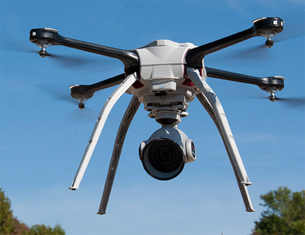
Aeryon Labs is partnering with Microsoft on its new Microsoft Advanced Patrol Platform (MAPP) vehicle. Microsoft has chosen Aeryon’s SkyRanger UAV to demonstrate aerial image and data capture for MAPP.
Aeryon Labs is a provider of small Unmanned Aerial Systems (sUAS) for military, public safety and commercial operators worldwide.
“Law enforcement organizations throughout the world rely on Aeryon sUAS to collect aerial intelligence wherever and whenever they need it,” said Dave Kroetsch, president and CEO of Aeryon Labs Inc. “Including SkyRanger within the MAPP vehicle rounds out the comprehensive suite of technologies and highlights the value of aerial intelligence for ground-based personnel.”
Aeryon Labs’ SkyRanger UAV provides real-time intelligence to law enforcement. (Photo: Aeryon Labs Inc.)
MAPP will connect its drivers to helpful and easy-to-navigate information, Aeryon said. Currently, patrol officers spend vast amounts of valuable time bound to their cars, clicking between windows on bulky, often dated laptops. MAPP will consolidate the many elements officers must keep track of — providing dispatch information, driving directions, suspect history, a voice activated license plate reader, a missing persons list, location-based crime bulletins and statistics, a feed of shift reports and more.
For first responders, surveillance teams and investigators, high-quality aerial imagery provides the real-time intelligence needed to assess a situation immediately, ensure safety on the ground, and capture detailed evidence and forensics. By integrating aerial images from Aeryon sUAS with other cutting-edge hardware and software solutions, the MAPP program sets a new technological standard in policing and helps officers operate with better awareness, efficiency, mobility and safety.
Aeryon Labs is showcasing the integrated solution at the IACP 2015 law enforcement and public safety conference, being held Oct. 25-27 in Chicago.