The Federal Aviation Administration (FAA) has issued additional drone flight restrictions over U.S. federal prisons, military bases and Pearl Harbor, effective Feb. 26.
At the request of its federal security partners, the FAA is using its existing authority under Title 14 of the Code of Federal Regulations (14 CFR) § 99.7 — “Special Security Instructions” — to address concerns about drone operations over national security sensitive facilities by establishing temporary unmanned aircraft system (UAS) specific flight restrictions.
Information on the FAA Notice to Airmen (NOTAM), which defines these restrictions, and all of the currently covered locations, can be found at the FAA’s UAS Data Display System, which provides an interactive map, downloadable geospatial data, and other important details.
A link to the restrictions is also included in the FAA’s B4UFLY mobile app.
Additional, broader information regarding flying drones in the National Airspace System, including frequently asked questions, is available on the FAA’s UAS website.
In cooperation with Department of Justice (DOJ) and Department of Defense (DOD), the FAA is establishing additional restrictions on drone flights up to 400 feet within the lateral boundaries of the following federal facilities:
Federal Correctional Institution Allenwood Medium in Allenwood, PA
Federal Correctional Institution Beaumont Medium in Beaumont, TX
Federal Correctional Institution Butner Medium I in Butner, NC
Federal Correctional Institution Butner Medium II in Butner, NC
Federal Correctional Institution Coleman Medium near Sumterville, FL
Federal Correctional Institution Florence in Florence, CO
Federal Correctional Institution Forrest City Medium in Forrest City, AR
Federal Correctional Institution Hazelton near Bruceton Mills, WV
Federal Correctional Institution Lompoc in Lompoc, CA
Federal Correctional Institution Oakdale I in Oakdale, LA
Federal Correctional Institution Oakdale II in Oakdale, LA
Federal Correctional Institution Petersburg near Hopewell, VA
Federal Correctional Institution Pollock in Pollock, LA
Federal Correctional Institution Terre Haute in Terre Haute, IN
Federal Correctional Institution Tucson in Tucson, AZ
Federal Correctional Institution Victorville Medium I in Victorville, CA
Federal Correctional Institution Victorville Medium II in Victorville, CA
Federal Correctional Institution Yazoo City Medium in Yazoo City, MS
Federal Detention Center Honolulu in Honolulu, HI
Federal Detention Center Houston in Houston, TX
Federal Detention Center Miami in Miami, FL
Federal Detention Center Philadelphia in Philadelphia, PA
Federal Detention Center SeaTac near Seattle, WA
Federal Medical Center Carswell near Fort Worth, TX
Federal Medical Center Fort Worth in Fort Worth, TX
Federal Medical Center Rochester in Rochester, MN
Metropolitan Correctional Center Chicago in Chicago, IL
Metropolitan Correctional Center New York in New York City, NY
Metropolitan Correctional Center San Diego in San Diego, CA
Medical Center for Federal Prisoners Springfield in Springfield, MO
Metropolitan Detention Center Brooklyn in Brooklyn, NY
Metropolitan Detention Center Guaynabo in Guaynabo, PR
Metropolitan Detention Center Los Angeles in Los Angeles, CA
Fort Detrick in Frederick, MD
Fort Gordon near Augusta, GA
Fort Lee near Richmond, VA
Holston Army Ammunition Plant near Kingsport, TN
McAlester Army Ammunition Plant in McAlester, OK
Radford Army Ammunition Plant in Radford, VA
Joint Base McGuire near Trenton, NJ
Pearl Harbor Naval Defense Sea Area in Honolulu, HI
These changes, which have been highlighted by FAA NOTAM FDC [9/2586], are pending until they become effective on Feb. 26. Note that there are only a few exceptions that permit drone flights within these restrictions, and they must be coordinated with the individual facility or the FAA.
Operators who violate the flight restrictions may be subject to enforcement action, including potential civil penalties and criminal charges.
The FAA is continuing to consider additional requests by eligible federal security agencies for UAS-specific flight restrictions using the agency’s § 99.7 authority as they are received. Additional changes to these restrictions will be announced by the FAA as appropriate.
Why abandon well-worn mapping methods in current use?
It has to be for one or more forms of gain: time, money or staffpower. UAV-borne lidar can save a lot of field time, eliminate the need for site revisits, capture more data than previously possible, and provide a better product using more automated extraction tools.
Surveyors and other mappers must frequently develop a reliable surface model of an area about to undergo major construction. If it is new construction over native soil, then the area is often covered with vegetation ranging from short grass to very tall trees. By far the majority of these areas are surveyed using GPS, total stations, levels or some combination thereof, depending on the project. In any case, at least one trained individual, more often two or even three individuals, must walk the area collecting the necessary data with some form of survey equipment.
This is the tried-and-true methodology. It is easy to schedule, easy to estimate, and barring any field or office mistakes, absolutely reliable. Manually visiting a point in the field on return visits should yield similar, though not exact, results, at least within the tolerances of the equipment. It doesn’t matter if the temperatures are near freezing or over 100 degrees. It doesn’t matter if it is raining or sunny. It doesn’t matter if the grass is cut or if the leaves are on and in full glory. This is a very reliable method in all respects, assuming the proper tools and techniques are used.
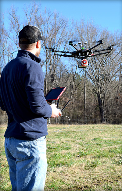
Piloting a lidar-equipped drone. (Photo: Bailie McRae)
How can this type of field survey be improved upon? First, is the product sufficient? Does the field crew reliably capture all the pertinent features? Did they get the location of the trees, buildings, poles and so on?
How many site visits are usually required to complete the average project?
What about the elevation data? Did they capture the drainage and breaklines sufficiently?
As always, the driving question is: Why change? Why abandon well-worn methods in current use?
It has to be for one or more forms of gain: time, money or manpower — which often equates to one or both of the first two terms.
When surveying with conventional equipment such as total stations, levels, and even GPS equipment, the likelihood of failure of a tried and true system is not very great. Comparatively, when using a UAV lidar system, not only are the stakes higher (as the equipment costs more), but the likelihood of an all-out failure is more likely and is definitely more devastating. There is no quick fix if your UAV crashes. It is more likely that the UAV will crash (usually due to operator error) than the lidar system itself will fail.
Facing these concerns, does one embrace a UAV lidar solution or hold to the tried and true?
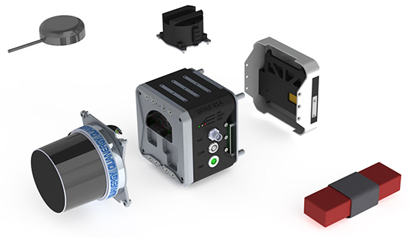
EQUIPMENT: Left to right, from top down: GPS antenna, laser head (Quanergy M8), detachable mount (car & UAV), computer and INS (GNSS receiver + IMU), interface plate, battery. (Photo: Lidar USA)
If it is important to get a heavily wooded 40- to 100-acre job collected and delivered as a surface at 1-foot contour accuracy (or maybe even 0.5 foot) in a single day, then UAV lidar is the tool for the job. UAV lidar can save a lot of field time, eliminate the need for site revisits, capture more data than previously possible, and allow for a better product using more automated extraction tools.
Accuracy. Often the client wants a 3D point cloud, or digital elevation model (DEM), which is not necessarily derived from lidar. If the site has no vegetation present, then an image-based solution should be sufficient.
However, most sites are initially covered with vegetation. In that case, an image solution from some sort of aerial camera will only provide a surface on the top of the vegetation — not what the client wants. While lidar may not be perfect, it can get to within 0.1 to 0.2 feet of the ground surface, in spite of grass or trees. For most initial design surveys, this is all that is required.
Money. Cost is perhaps the topic of greatest persuasion against lidar and in favor of an image-only solution. A lidar system is more expensive than most camera systems, but again the camera system simply cannot collect viable ground data in vegetated areas.
Time. Another factor is the time required to become profitable with the system, and the longevity of the system. In a good economy, it doesn’t take many 40-acre topo jobs to completely pay for a UAV lidar system. Once more, it is about time.
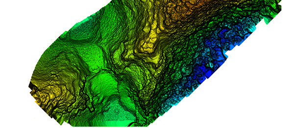
Broad overflight area of the cloud forest. (Image: Lidar USA)
As to product longevity, any new UAV product released today should be just as functional in five years. You may have to upgrade your UAV, but the lidar system will still be good for the jobs we’re discussing.
Lidar collects XYZ and intensity. It does not collect RGB values. This is a strike against lidar. While lidar data can be colorized with imagery captured from a camera on the same system as the lidar, or separately, this is generally discounted as being imprecise (not well aligned). Lidar does not inherently or directly capture color. However, imagery is 2D in nature and does not capture XYZ data.
Imagery can align with the lidar nearly perfectly; it is a matter of a good boresight.
UAV photogrammetry, or image-only solutions are amazing. They provide a wealth of information. They are complementary to and synergistic with UAV lidar.
The advantages of including a UAV lidar solution along with a UAV photogrammetry solution include:
the ability to measure at any time, day or night, in bright light or no light;
rapid surface generation (not instant, but fast);
flat surfaces, vertical walls, overhead structures — everything is collected without difficulty;
power lines, guy wires and so on are all collected directly,
bare-earth collection (multi-echoes and direct collection to ground, not just top of vegetation) is possible;
generally a much wider collection width and fewer flight lines.
Further, lidar can often penetrate dust, fog and mists.
Sensors and Their Issues
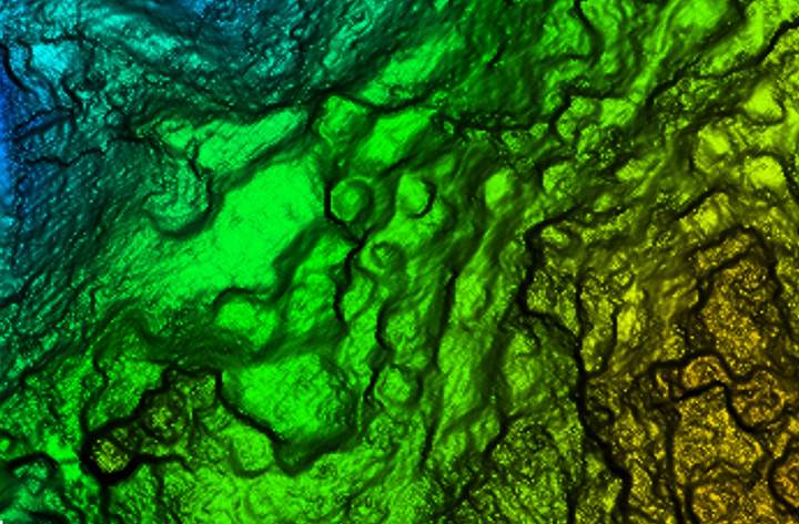
Bare earth classified surface of small site. (Image: Lidar USA)
Lidar does require an inertial navigation system (INS) and all of the controlling software. This generally makes the system more expensive. It also makes it able to more rapidly generate the final product.
Inertial Use with Lidar. An INS combines a GNSS receiver with an inertial measurement unit (IMU) and a lot of software and specialized filtering algorithms. It is essentially the central nervous system of a lidar system. The GNSS receiver provides universal timing such that every instrument including the IMU, scanner, cameras and others are all precisely time-stamped. This is key to proper data fusion. The GNSS receiver also provides positioning. The IMU is essential for determining proper orientation (roll, pitch, heading) as well as positioning at an extremely high data rate (2000 Hz) between the recorded GNSS epochs. If a GNSS event is missed (which shouldn’t happen on a UAV) the IMU bridges the gap between epochs. Large gaps can lead to positional drift, but shouldn’t happen on a UAV.
The real-time software maintains satellite lock (coupling with the IMU as necessary), while the post-processing software, using a post-process kinematic (PPK) process, provides the best possible solution of the trajectory. It solves the trajectory forward, backward and over and over with different parameters until it reaches an optimum solution. So it’s not just the hardware that makes the system more expensive, it’s also the software.
Closer site inspection — notice non-natural occurring mounds. (Image: Lidar USA)
Double Duty? There is some confusion as to the INS on a UAV. Can the INS used to navigate the drone be used for the lidar system as well, to save money? Yes, and no. Yes it can, with the proper integration — however, the INS to navigate the drone is usually far, far inferior to that required by a lidar system. So, No. Also, the lidar system really should be portable from the UAV to a car to maximize use. So the systems need to remain separate, for the most part.
Height and Width. Another UAV sensor issue concerning lidar is often very confusing. Some sensors are only good for 40- to 60-meter flying heights; some are useful to 200 or more meters. Depending upon where you work, this may be of no concern. In the U.S., we are limited to 120 meters above ground level (AGL) in any case. In most areas, being able to fly at 80 to 100 meters AGL is sufficient as long as accuracy and point density are not compromised.
Scan width varies a lot as well. The scan width of the shorter range systems is typically no more than 150 meters of usable area, whereas others can scan 500 meters wide. Consider that most surveys are 40 acres, maybe up to 100 acres, and we find that one flight is all that is necessary even with the least-expensive system. Do you need 500 meters wide? The answer depends upon your business model. If you are doing miles and miles of transmission corridor work, you probably need the greater width.
Ground Accuracy. What matters here is not so much positioning accuracy but point-cloud thickness. This can be difficult to understand and is a worthy subject by itself. The question is whether you can deliver the product you most often are required to deliver with the system. If you deliver 1-foot contour projects, can you achieve this with a 6-centimeter system or do you have to have a much more costly 1-centimeter system? Clearly the 1-centimeter system is much better, but what do you need to deliver?
Intensity is another concern. Most of the less expensive systems don’t do a very good job delivering a “b+w image-like” point cloud; that is, their intensity falls off dramatically with distance. Others do an amazing job. Is this important? Can it be overcome with colorization? If you were doing your work conventionally, would you be delivering an image-like surface? I doubt it. Certainly the intensity is nice to have and the information can be very useful in automated processing, but is it worth the price difference?
Ultimate Test: the Jungle
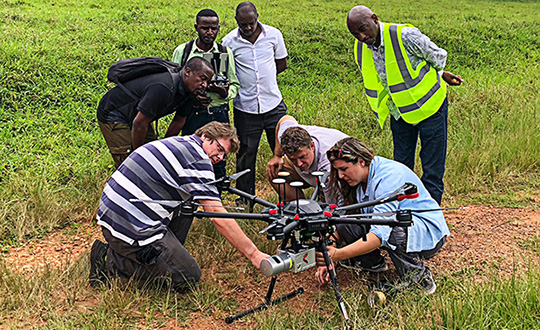
Recently we undertook an adventure with some explorers in South America, near the city of Jaen, Peru. A crew filming a new TV show for the Travel Channel sought to understand more about the ancient civilization of Chachapoyas, Warriors of the Clouds. Little is known about this race of people because they were conquered by the Incas in the 16th century and shortly thereafter by the Spanish conquistadores.
Our team was to help identify structures in an area called Leymebamba, about four hours’ drive from Jaen, hidden beneath the deep Amazon cloud forests — definitely not a typical North American forest. These forests are not only very dense with vegetation but with cloud cover that is generally at the level of the canopy.
Many centuries after the Chachapoyas have vanished, structural remains are concealed not only by the clouds and the canopy, but buried beneath several feet of dirt and a lot of living and long-since-dead organic matter. Only the most pronounced features can be found by the naked eye or a traditional survey.
Lidar brings a huge advantage in that it can get a much better approximation of the ground as well as any other hard surface such as walls, fences, trails, buildings and towers. By blanketing an area with dozens if not hundreds of points per square meter, post-processing software can “peel” the living vegetation away from the ground surface. This ground-classified data can then be analyzed by a trained scientist to determine if there are in fact any revelations to be had.
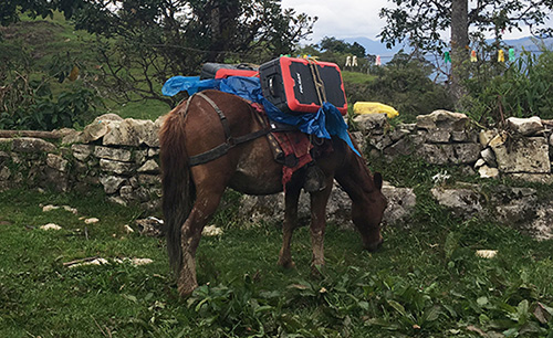
In our case, we were using an A-series high-definition lidar system, best flown at 40 to 60 meters and, in extremely dense vegetation, at 5 to 6 meters/second. Collecting 700,000 points per second enables us to potentially capture more than 400 points per square meter in a single pass. The area we were to scan varied considerably in terrain and had very little to offer that was flat and open. In fact, to get to the site, we had to pack several mountain horses with the UAV, several sets of batteries, and the scanner as they traveled down very steep terrain about 900 feet to the base of the hill to be scanned.
We’ve said we can scan from nearly anything moving, but we’ve never done it from a horse. Well, we weren’t actually scanning, but it was pretty close.
UAV and lidar, bound for the cloud forest. (Photo: Forrest Briggs)
Finding a suitable take-off and landing area posed a challenge. Due to vegetation and terrain, only small areas could be scanned in a single flight, as the vehicle would quickly leave line-of-sight (LOS). While LOS may not be an issue legally in this area, it remains a real concern: we always want our equipment to come home at the end of the mission.
We learned something we hadn’t anticipated along this journey regarding weather. The day would start out around 80° F; around 2 p.m. it would rain, and the rest of the day would close out much cooler. Does this matter? Yes, if you are now wet and cold with several hours ahead of you. It seems there is always some new surprise.
As the area was remote, with no internet access, the existing map data for mission planning had to be downloaded prior to visiting the site. Each lidar mission was preceded by a scout flight using a small UAV to help ensure safety and appropriate flying height per flight line.
Situating the Base. Projects like this always pose dilemmas. Finding a good place for a GPS base station in a cloud forest is no small task. Normally we would put the base station on a known reference point so we can easily join the data with other projects. In this case we didn’t have any such concern. We simply needed an area with a clear view of the sky; usually this means no obstructions 12 degrees above the horizon. However, in a forest and in the mountains, you take what you can get. In our case, we found a rock outcropping and placed the unit on it with no tripod. It didn’t give us the best solution, but it worked.
Ideally we leave the base running for hours to get a good solution. Since we had multiple sites to scan, this wasn’t a problem. All sites were within walking distance of the base, so there was no concern about being too far away and adding more problems to the project. In PPK mode we can easily be 10 or 20 kilometers from the base with no concern.
Other Forest Challenges. In-field processing, far from internet or electrical supply, requires very judicious battery and especially laptop usage. The lack of many things we take for granted can quickly be a show-stopper if necessary (maybe even a phone call).
Even back at the hotel where power was available — don’t count on it. While the film crew and archeologists are eager to see results, everybody has to wait. No power.
Supposedly this is common and only lasts an hour. Three hours pass and everybody goes to bed but the lidar crew.
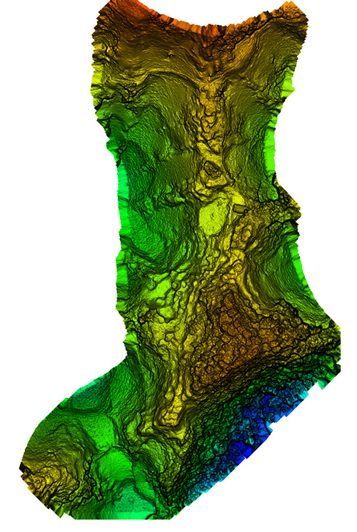
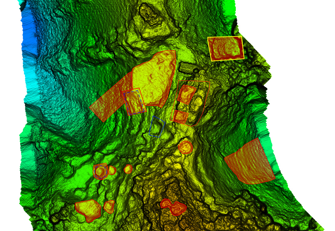
Areas of interest to archeologist — lots of them. (Image: Lidar USA)
Finding the ground should be easy, but a new version of software has been installed. There’s a kink in our plans. Finally after some internet help (a call back home), the right settings are found and the software begins peeling away the vegetation to reveal the ground. The top of each hill (several were scanned) looked like a primitive fortress with 20 to 30 cylindrical structures clearly spread over the top of each site. On one site we identified a tower at least 3 meters in height.
While areas like this could be scanned with a conventional aerial system, collecting much larger areas, the UAV lidar solution offers several distinct advantages. One of these is just a quick recon of the area. Physically being on the ground at the site makes the team much more aware of what is going on. Secondly is the far, far greater density of points and the ability to collect much more off-nadir, allowing for more of the vertical structure to be captured.
In the end, our mission was successful. The UAVs were ported by horseback up and down precarious trails. The lidar worked great. None of the batteries failed. The drones didn’t crash. The archeologists were thrilled with the results, having found several new structures and a tower unknown to them. Once again, UAV lidar proved to be the best tool for the job. Indiana Jones out!
Manufacturers
As both INS sensors and lidar scanners continue to change, this allows us to make quite a variety of configurable systems. For this particular project, we used our Snoopy INS (OEM) with a Quanergy M8 Ultra scanner. The Snoopy INS uses a NovAtel OEM719 GNSS receiver to ensure best performance with GNSS collection. Other options for the INS include the NovAtel STIM300 (Sensonor IMU), VectorNav VN-300 and Trimble Applanix AP family. For scanners we support all Velodyne scanners including the latest AlphaPuck, Quanergy, Riegl and several more. Of course, for cameras there are the ever-popular FLIR, Sentera, PhaseOne and DJI. GPS base stations are not all equal, but most will work as long as they log at least L1/L2 GPS at 1Hz.
JEFF FAGERMAN is a a professional surveyor and certified photogrammetrist. He has a master’s degree in photogrammetry from Purdue University and worked as a photogrammetric software developer at Intergraph before starting Fagerman Technologies. Now known as Lidar USA, the company focuses on mobile lidar aboard UAVs.
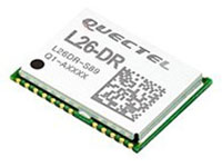
The L26-DR dead-reckoning GNSS module is a multi-GNSS receiver embedded with a dead-reckoning solution to greatly improve positioning accuracy and speed while simplifying customer designs. The dead-reckoning capability ensures the module delivers the highest performance positioning solution available, even when GNSS signals are absent or compromised. Equipped with six-axis sensor MEMs and a powerful GNSS core, the module provides high sensitivity, fast GNSS signal acquisition and tracking with low system integration effort. The L26-DR can acquire and track any mix of GPS, GLONASS, BeiDou, Galileo and QZSS signals.
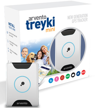
The Arvento Treyki Mini is a compact people and asset tracking device with eight operating modes, including special settings for tracking children (with geofencing) and senior citizens (with an integrated fall sensor). It is also suitable for use in sports, racing and asset management and can be used as an emergency beacon. It has an onboard positioning receiver, and reports its location using an internal GSM/GRPS modem. It can operate for up to seven days from its 900mAh LiPo rechargeable battery before it needs to be recharged. It uses the u-blox ZOE-M8Q concurrent multi-GNSS module, which is able to receive 72 channels simultaneously.
The new Antenova Raptor achieves high accuracy using the L2 1200-MHz GNSS bands. The L2 band combines multi-band satellite signal reception and GNSS correction data, helping to mitigate position errors. The antenna is the latest addition to Antenova’s lamiiANT range of rigid FR4 antennas designed for easy insertion onto a printed circuit board (PCB). It is a GPS single-feed antenna in surface mount (SMD) form, measuring 16.0 x 8.0 x 1.6 millimeters, suitable for small PCBs within all kinds of small electronic devices. Raptor is supplied in tape and reel for ease in high-volume manufacturing applications.
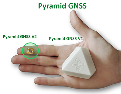
The Regulus Pyramid is a fully functional GNSS receiver fortified with spoofing detection capability. The receiver contains patented technology that enables it to differentiate between real GNSS signals and fake ones generated by an attacker. It is availble both as a fortified GNSS receiver (v1), capable of detecting spoofing attacks, and at the chip level (v2), allowing mobile phones, cars and internet of things (IoT) devices to receive GNSS spoofing protection. A Pyramid GNSS Add-On can be integrated with another satellite receiver to enable spoofing detection capabilities for any GNSS board.
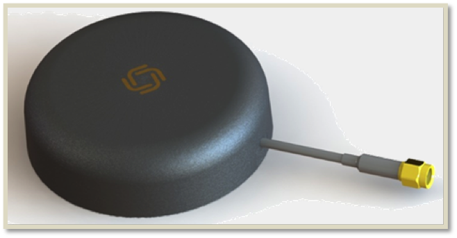
The AGR6302 and AGR6303 GNSS patch antennas are designed for precision dual-frequency positioning. The AGR6302 is capable of receiving L1/L2 bands, and the AGR6303 is capable of receiving L1/L5 bands. They are designed for UAVs, precision agriculture, autonomous vehicles and other applications where precision matters. The AGR6302/AGR6303 active antenna is designed to cover GPS, BDS, Galileo, GLONASS, IRNSS and the QZSS system. It employs a stack four-feeds architecture with hybrid to achieve the multi-band operation, lower axial ratio, wider half-power beamwidth and excellent right-hand circular polarization. It is housed in a compact, industrial-grade waterproof and magnet mount enclosure.
The Alta 8 Pro multi-rotor drone includes waypoint technology to allow preprogrammed movements and autopilot functionality. The Alta Pro flight controller runs open PX4 flight stack for quick and powerful interfacing. The Alta 8 Pro fuses readings from accelerometers, barometer, and GPS to create high-bandwidth height control flight mode. By fusing GPS data with an IMU and barometer, the drone is able to hold position even in difficult weather conditions.
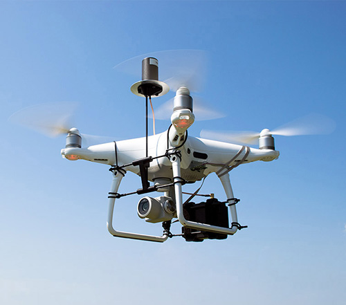
DJI Phantom 4 Pro with Loki PPK system. (Photo: GeoCue)
The DJI Phantom 4 Pro RTK (P4R) drone is now integrated into the AirGon Sensor Processing Suite (ASPSuite). ASPSuite is a post-processing solution for GeoCue’s Loki direct geopositioning system for DJI and other drones. The ASPSuite enables integration of the P4R with third-party L1/L2 GNSS base stations such as systems from Septentrio, Leica, Trimble, Topcon, CHC and others in a high-accuracy PPK workflow. It includes support for engineering-grade survey options such as vertical transforms, creation of and transformation between collection datums and local coordinate systems, application of antenna static and dynamic lever-arm corrections, and full support for Loki direct geopositioning systems.
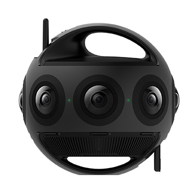
The Insta360 Titan is an eight-lens cinematic virtual reality (VR) camera that captures 360-degree photos and video at up to 11K resolution. The Titan uses eight micro four thirds (MFT) sensors, the largest sensors available in any Insta360 standalone VR camera. It has a GPS signal antenna and a Wi-Fi signal antenna. The sensors maximize image quality, dynamic range, low-light performance and color depth, increasing realism in high-end professional VR capture.
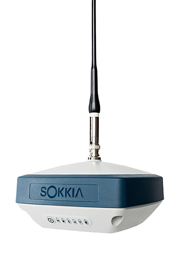
The GRX3 is designed to provide a smaller, lighter and fully integrated GNSS solution to Sokkia’s GNSS receiver line. Its compact and lightweight housing has been tested to meet IP67 certification for protection against harsh weather. The receiver features Sokkia Tilt technology, which includes a nine-axis inertial measurement unit (IMU) and compact eCompass designed to compensate for misleveled field measurements by as much as 15 degrees. UTC technology automatically tracks signals from all available and planned constellations, including GPS, GLONASS, Galileo, Beidou, IRNSS, QZSS and SBAS.
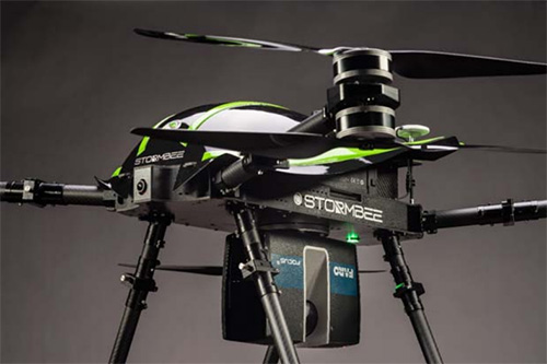
The Faro Focus scanner attached to a Stormbee UAV. (Photo: Stormbee)
The Faro–Stormbee airborne solution includes the Faro Focus laser scanner, the Stormbee S series UAV and the Beeflex software suite. It enables wide-area scanning missions such as highways, train infrastructure and buildings. It allows users to capture complex environments traditionally inaccessible to ground-based scanning. It has no need for control points. Users can create centimeter-level accurate point clouds directly from the in-flight data.
Experts discuss value of automation and new technology
Screenshot: Topcon
The new Infrastructure and Technology series of documentary videos is designed to foster awareness of growing global infrastructure demands and the technology that can help meet them. Experts interviewed include representatives from Intel, SAP, Industry Consultants, Constructech, Solar City and Topcon. They discuss how, by adopting technology, the construction and agriculture industries can increase productivity and help address infrastructure needs now and in the future.The series was filmed globally in the U.S., the Netherlands, the United Kingdom and Germany.
Updated to latest intellicad technology consortium release
Photo: Carlson Software
The specialized drafting package Carlson iCAD 2019 allows technicians to supplement the finished product in their project deliverables. New additions and functions to the iCAD 2019 release are new tool palettes, new 3D solid commands, additional DGN support, and new express tools. iCAD features Google Earth import and export KML/KMZ, standard CAD entities and the drawing inspector tool.Carlson iCAD 2019 has been built with and updated to the IntelliCAD 9.0 engine from the previous IntelliCAD Technology Consortium 8.3 release. IntelliCAD 9.0 supports direct read of DGN files, allowing users to make edits without converting drawing formats, and features a CUI interface for custom workspaces, toolbars and ribbons.
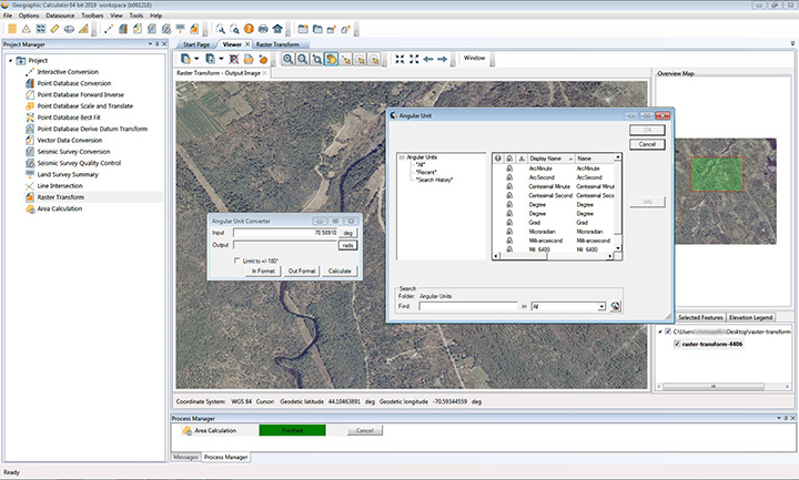
The 2019 Geographic Calculator features a universal copy and paste function, a new angular unit conversion tool, support for NADCON 5.0 and updated seismic survey conversion functionality. The foundation of the calculator’s geodetic data-processing functionality is the embedded GeoCalc datasource, which is continually revised and improved with updates through the online GeoCalc Geodetic Registry. The datasource included in the 2019 release mirrors the most current EPSG database definitions. The calculator’s copy and paste function can be used to quickly capture data for use in a third-party application or to insert new coordinate values in an existing job.
The InvenSense Coursa Drive software is an inertial-aided positioning solution for autonomous vehicle platform developers. It is a high-performance extension of the InvenSense Positioning Library (IPL), which has provided sensor-aided positioning to more than 50 million devices worldwide. Coursa Drive enhances inertial-only vehicle positioning to <0.2 percent of distance traveled, accuracy critical to maintaining decimeter lane-level vehicle positioning in challenging GNSS/perception system environments. Coursa Drive’s inertial navigation system (INS) calibrates using absolute position inputs from either high-accuracy GNSS receivers or from perception-based systems (camera, radar, lidar) with high-definition (HD) maps. In real time, Coursa Drive provides high-rate, 100-Hz delta positions and orientation to the autonomous vehicle system, complementing the lower rate position references from GNSS and perception systems. For non-real-time applications such as HD map creation and maintenance, Coursa Drive’s offline mode reprocesses INS data at two to three times higher accuracy than real-time mode, providing HD map companies alternative position references to verify HD map accuracy, even without GNSS, for up to 60 seconds.
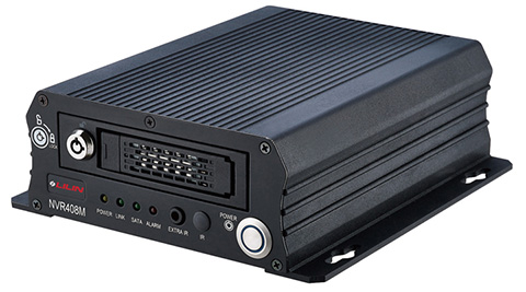
The mobile NVR408M with GPS navigation is designed for use in moving vehicles, remote locations or rugged environments. The rugged compact design works in harsh and demanding conditions to deliver quality video surveillance. Typical applications are in law enforcement or public transportation, using vehicles such as trains, buses, trucks, cars, airplanes and ships. NVR408M is an EN50155-certified product, able to withstand severe vibration and shock and making it suitable for railway applications.
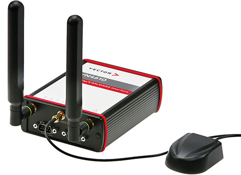
The VN4610 is a powerful interface for accessing IEEE 802.11p and CAN (FD) networks for Car2X/V2X communication using a USB PC connection. The VN4610 provides precise position, time and speed information that can be used by the application as test stimulus or for documentation. The absolute GNSS timestamps can be used to synchronize recordings of distributed measurements for subsequent analysis. The u-blox NEO-M8U supports GPS, GLONASS, Beidou and Galileo — up to three systems simultaneously. The IEEE 802.11p-based dedicated short-range communication (DSRC) communicates in the 5.9-GHz range. The VN4610 supports the unfiltered receiving and sending of IEEE 802.11p frames used for the implementation of Car2X/V2X applications. The received IEEE 802.11p radio-signal-based frames are transferred to the application synchronously to the CAN (FD) messages.
With enhanced ADS-B, SBAS and georeferenced charts
Photo: Collins Aerospace
The Pro Line Fusion avionics upgrade for Pro Line 4-equipped Bombardier Challenger 604 series aircraft has been certified by the U.S. Federal Aviation Administration (FAA). The all-in-one upgrade complies with pending mandates while modernizing the flight experience for pilots. The upgrade includes ADS-B mandate compliance, SBAS-capable GNSS, localizer performance with vertical guidance (LPV) approaches, radius-to-fix (RF) legs, geo-referenced electronic navigation charts, widescreen LCD screens and synthetic vision.
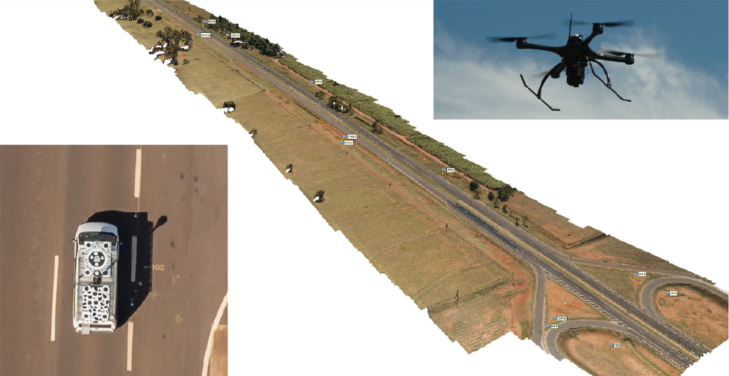
Kinematic Ground Control point for UAV photogrammetry: A dynamic duo of UAV and mobile van combine to deliver the accuracy of conventional methods with only 2+2 ground control points at the ends of the corridor.
By Ismael Colomina, Pere Molina and Roberto da Silva Ruy
A Brazilian and a Spanish company, ENGEMAP and GeoNumerics respectively, have finalized the accuracy evaluation of a mission conducted with the latter’s mapKITE technology on a Brazilian motorway in 2018.
The goal of the evaluation was to confirm the advantages of the mapKITE method and its kinematic ground control point (KGCP) concept over conventional corridor mapping methods.
The mapKITE and the conventional method delivered comparable accuracy results — the difference being that the latter requires a dense set of surveyed ground control points (GCPs) while mapKITE does the job with almost no GCPs.
For this purpose, a 4-kilometer segment of the Rodovia Raposo Tavares in São Paulo state was populated with a set of 37 evenly distributed, signalized, accurately surveyed ground points. The set was divided into two subsets of 23 GCPs and 14 ground check points (GChPs) — the ground truth — respectively. The 4-km road segment was also covered by 189 drone images and their corresponding 189 KGCPs. The image set was processed as a conventional aerial corridor block:
with the integrated sensor orientation (ISO) method in a 23 GCP + 14 GChP configuration, and
as a mapKITE aerial corridor block in a 4 GCP + 14 GChP + 189 KGCP configuration.
The two processes produced similar accuracy results: mean (μ), empirical standard deviation (σ) and root mean square (rms) error of the photogrammetric determination of the horizontal (EN) and vertical (h) coordinates of the GChPs against the ground truth. (All units are stated in millimeters.)
The mapKITE configuration uses only four GCPs (two at each end of the road segment) in contrast to the 23 GCPs of the conventional method. Nominal flying height of the drone was 120 meters above ground, producing an average ground sampling distance (GSD) of 2.3 cm. Forward image overlap was 80% resulting in a base-to-height ratio of 0.157.
MapKITE is a GeoNumerics patented method for 3-dimensional corridor mapping that combines the two latest geodata acquisition methods, terrestrial mobile mapping and aerial drone-based mapping. MapKITE is a tandem terrestrial-aerial mapping method and system composed of:
a terrestrial mobile mapping system (land vehicle and sensors) carrying
an optical metric target on its roof;
a drone aerial mapping system; and
a real-time virtual tether and post-mission software.
In a mapKITE mission, the drone follows the land vehicle, and thus the vehicle target becomes a kinematic ground control point visible and measurable on each image. It is a high-accuracy, high-resolution Earth observation method. MapKITE combines the advantages of mobile land-based encompassing images and 3D point clouds. MapKITE combines the advantages of mobile land-based (manned) and aerial drone (unmanned) mapping systems.
GeoNumerics (Castelldefels, Spain) is a research and development company specializing in geomatics and accurate navigation.
ENGEMAP (Assis, Sao Paolo, Brazil) is one of the largest and oldest mapping companies in Brazil. It has more than 100 employees, three aircraft, two mapping land vehicles, a number of rotary- and fixed-wing drones and a record of accomplished mapping and cadastral projects. ENGEMAP is officially authorized by the Brazilian Ministry of Defence (MD) and the Brazilian Department of Airspace Control (DECEA) to conduct mapKITE commercial flights in Brazil.
MANUFACTURERS
The mapKite campaign was conducted with a Sensormap SMM terrestrial mobile mapping system and a UAVision UX Spyro drone equipped with a NovAtel OEM2 GNSS dual-frequency receiver with a Maxtena antenna and a Sony α7R camera with a 25-mm camera constant lens. The INS/GNSS system in the Terrestrial Vehicle was a Span-CPT (Novatel) including dual-frequency antenna and DMI wheel sensor.
ISMAEL COLOMINA is chief executive and chief scientist at GeoNumerics. He has a Ph.D. in mathematics from the University of Barcelona.
PERE MOLINA is advanced applications program manager at GeoNumerics. He holds a master’s degree in mathematics from the University of Barcelona and a master’s in photogrammetry and remote sensing from the Institute of Geomatics, Catalonia.
ROBERTO DA SILVA RUY is technical manager at ENGEMAP. He has a Ph.D. from the Universidade Estadual Paulista.
Are drones (UAVs) a disruptive or constructive technology for high-precision mapping that yields practical, actionable results for the end user/customer?
Ismael Colomina
“More constructive than disruptive. Drone mapping is opening new markets that, to a large extent, were not serviceable by conventional manned flights. On the other hand, the profound changes — and crisis — in the mapping business were not produced by drones.” Ismael Colomina GeoNumerics
Jean-Marie Sleewaegen
“Drones have dramatically reshaped the surveying and mapping industry. Combined with reliable positioning and recent advancements in high-resolution cameras, photogrammetry and computer vision, drones now enable high-accuracy mapping faster and at much lower cost than conventional mapping techniques.” Jean-Marie Sleewaegen Septentrio
Jules McNeff
“Drones can be constructive augmentations to high-precision map products because of their ready access to diverse locations. Drone imagery can document real-time physical changes that affect mapping applications during natural disasters or other events — but images alone aren’t maps without a geo-referenced grid such as the U.S. National Grid.” Jules McNeff Overlook Systems Technologies Inc.
Other members of the EAB
Tony Agresta Nearmap
Miguel Amor Hexagon Positioning Intelligence
Thibault Bonnevie SBG Systems
Alison Brown NAVSYS Corporation
Clem Driscoll C.J. Driscoll & Associates
John Fischer Orolia
Ellen Hall Spirent Federal Systems
Terry Moore University of Nottingham
Bradford W. Parkinson Stanford Center for Position,Navigation and Time
Tesla has developed a technology aimed at providing more accurate positioning for autonomous cars by sharing data between vehicles, according to a U.S. patent application.
The patent, “Technologies for vehicle positioning,” was filed in 2017 and made public in December 2018.
Solutions include cameras detecting matching locations and using other vehicles in its fleet as “cooperative reference stations” to share raw GNSS data and make positioning corrections.
Tesla describes in the patent, “The inventions increase such positioning accuracy via determining and applying offsets (corrections) in various ways, or via sharing of raw positioning data between a plurality of devices, where at least one knows its location sufficiently accurately, for use in differential algorithms.”
Techniques include:
a reference station sharing a positional offset with an automobile,
a reference station calculating and sharing a set of parameters (offsets and corrections) for various error components including atmospheric, orbital and clock,
a reference station sharing its raw GNSS data so that vehicles can remove errors through differencing or other calculations.
Tesla also would correct GPS data by matching camera data with vision maps to detect the exact location of a vehicle. With this vision-map matching localization approach, “a location estimate is varied until the location estimate makes a camera-reported lane boundary coincide with a map-reported lane boundaries,” the patent reads.
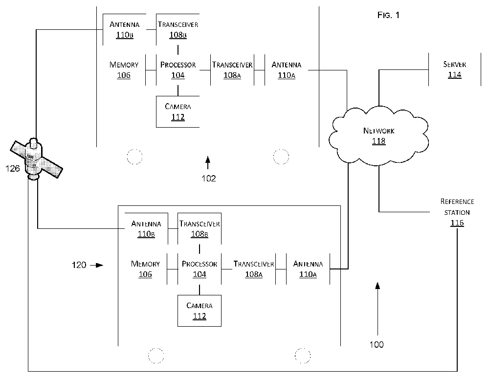
Schematic of Tesla’s system shows two vehicles (102, 120) feeding data to a network, a server and a reference station. (Image: Tesla)
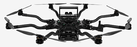
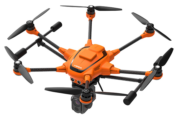
Yuneec International’s commercial hexacopter, the H520, will now optionally be available with an RTK (real-time kinematic) system from the Swiss company Fixposition.
Under difficult GPS conditions, such as in cities or canyons, the RTK system ensures maximum precision and centimeter-precise positioning. The fully integrated RTK satellite navigation enables extremely accurate recurring images and faster 3D mapping. It also makes automated inspection flights easier and more precise, the company said.
The new H520 RTK is suitable for commercial applications that require maximum precision. By using RTK technology, the H520 can now fly much closer to objects for inspection as the UAV positions itself precisely in the centimeter range (1 cm + ppm horizontal / 1.5 cm + ppm vertical) rather than in the meter range, which is standard for the H520.
This accuracy is paramount for applications where several images need to be taken at the same location on different days including:
documenting progress on construction sites,
inspecting mountain landscapes to prevent natural hazards such as rock falls or avalanches, and
forensic accident scene reconstruction.
In addition, the satellite navigation system makes it possible to significantly reduce image overlaps, which means fewer photos and shorter model calculation times, maximizing efficiency in workflows.
The RTK system is not only fully integrated into the hardware, but also into the UAV’s software. This means the user retains the full range of functions of the DataPilot software, including mission flights.
The H520 RTK works with two components: the RTK module on board the H520 and a base station on the ground. For precise navigation, the module supports constellations of up to three different satellite systems from GPS, GLONASS, Galileo and BeiDou.
If the use of a ground station is not possible, the system can also be operated with a national reference station network (network RTK). The network RTK is provided by third-party providers and requires an internet connection, such as a mobile hotspot. All data including satellite data is recorded, which makes the H520 RTK suitable for post-processed kinematics (PPK).
The H520 RTK will be available in the second quarter of 2019. Technical specifications are available here.
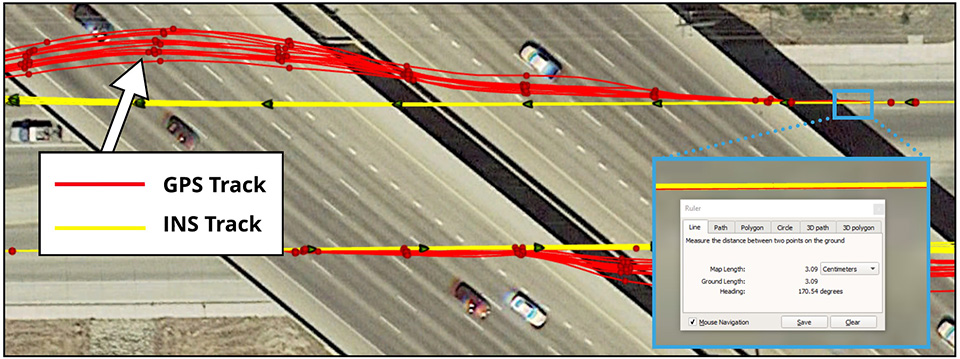
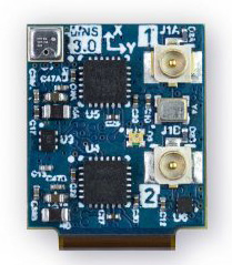
Dime-sized INS with RTK paves the way for high accuracy in mass-market consumer applications.
Photo: Inertial Sense
Inertial Sense has released a new micro-sized inertial navigation system (INS) with precise real-time-kinematic (RTK)-level accuracy. The company says the new solution paves the way for high accuracy in mass-market consumer applications.
The new micro INS with RTK solution offers an accuracy of 2-3 centimeters using GPS positioning in combination with inertial sensors (including on-board sensor fusion).
Inertial Sense designs and manufactures precision INS+RTK GPS sensors that deliver fast, accurate and reliable altitude, velocity and position for a wide range of autonomous vehicle applications, the company said.
The new micro INS with RTK provides a high degree of precision for orientation and GPS in a tiny package. Standard INS/GPS sensors offer accuracy in the range of 1.5 to 2 meters. Inertial Sense’s micro INS with RTK offers accuracy of 2-3 centimeters.
In the image above, a vehicle travels under an overpass. The 3-cm accurate RTK-inertial navigation track holds true to the vehicle’s position while the standard GPS signal is lost. (Image: Inertial Sense)
“The incredibly small size of our new micro INS with RTK sensor, in combination with its extremely affordable price point, will make this type of highly sophisticated technology accessible for general consumer applications for the very first time,” said Walt Johnson, founder and CTO, Inertial Sense. “We are offering RTK at a size, accuracy and price point that the market has never seen before.”
By optimizing the manufacturing processes for high volume applications, the micro INS with RTK sensor is as small and lightweight as a dime, and is available at a low price point.
Sensor fusion. Sensor data from MEMs gyros, accelerometers, magnetometers, barometric pressure and u-blox GPS/GNSS are fused to provide optimal position estimation. Data out includes angular rate, linear acceleration, magnetic field, barometric altitude and GPS time.
The miniature module provides orientation, velocity and position. Base station corrections data can be applied to achieve centimeter-level precision.
Autonomous vehicles. The sensor will enable the navigation of all types of autonomous vehicles with a very high degree of precision, Inertial Sense said.
Inertial Sense patented modules are currently being sold worldwide at volume for a broad variety of applications including:
Aerial surveys: UAV Payloads for 3D mapping, photogrammetry, orthomosaics
Gimbal stabilization and antenna pointing
3D motion capture and personnel tracking
Evaluation kits. Inertial Sense has bundled evaluation kits it says are simple to use and contain everything needed to begin logging RTK-accurate data. The evaluation boards can be utilized in both rover and base station configurations and include 900-mhz radios with onboard logging capabilities.
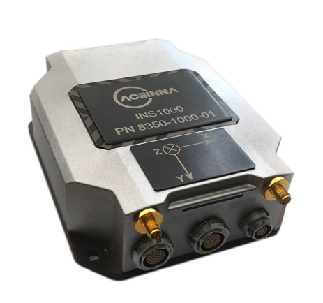
Centimeter-accurate, multi-constellation, multi-band, dual-antenna, RTK and affordable GNSS/INS solution
Aceinna is offering the INS1000 high-performance dual-band real-time kinematic inertial navigation system (RTK INS) with built-in inertial sensors for construction, agriculture and automotive applications.
Aceinna has also launched an OpenIMU package for autonomous vehicle guidance and navigation.
INS1o00
Photo: Aceinna
The INS1000 embeds Aceinna’s nine-degree-of-freedom inertial sensor technology to achieve automotive dead-reckoning performance in GNSS-challenged environments like urban canyons, heavily tree-lined roads, tunnels, underpasses and bridges.
The dual-frequency RTK and tight coupling between GNSS and inertial sensors provide centimeter-level accuracy, enhanced reliability, and superior performance during GNSS outages, the company said.
“Without access to satellite delivered guidance and localization information, autonomous vehicles can quickly get off track,” says Mike Horton, CTO of Aceinna. “The INS1000 delivers the essential detailed position and heading accuracy at a price point that is suitable for startups as well as fleet-wide vehicle deployment. As the leading supplier to the precision agriculture autosteer market, Aceinna is focused on driving the cost and complexity out of GNSS/INS solutions to enable widespread adoption in automotive ADAS applications.”
INS1000 is an integrated navigation system consisting of an inertial measurement unit (IMU) and other sensors. It provides the position, velocity and attitude information of the vehicle. A dual-frequency (L1/L2), dual-antenna GNSS receiver is used as the primary aiding sensor. Also supported is a distance measurement indicator (DMI) which can be attached to a wheel of the vehicle/robot to measure the rotation rate of the wheel. Integration of a DMI would give an improved solution in challenging environments: urban canyons, tunnels, warehouses and indoor facilities and campuses.
With horizontal position accuracy of 2cm (RTK), vertical position accuracy of 3cm (RTK), and velocity accuracies of 0.01m/s and 0.02m/s (horizontal and vertical, respectively), the INS1000 provides the precision navigation capabilities required for the automotive autonomous, automotive track testing, precision agriculture, and construction markets.
The INS1000 is compatible with all major global satellite systems (GPS, GLONASS, Beidou, Galileo, SBAS); it supports USB, Ethernet, CAN and RS-232 interfaces; and it supports dual GNSS antennas for accurate heading in static and dynamic scenarios, and difficult magnetic environments.
The easy-to-use embedded software allows extensive configuration and diagnostic capabilities. For optimal flexibility, the tools enable configuration of the output position, initialization of heading, IMU transformation matrix, GNSS antenna lever-arms, and NTRIP client. The control software can log and decode output data from the system or use the web application to plot results on a map.
Open IMU Package
Aceinna also offers an OpenIMU package. Its three key parts are:
a family of IMUs (three high-accuracy accelerometers, three high-accuracy gyros, and a powerful ARM Coretex);
an OpenSource tool chain and reference code for programming the IMU, with everything from basic download and debug to reference implementations of loosely coupled GPS/INS
a full developer site and tools with charting, graphing and algorithm simulation.
Looking around the industry over the last few weeks, there continues to be a flood of innovation that promises new approaches for unmanned aircraft in addressing several new opportunities. This month I cover a flying taxi at the 2019 Consumer Electronics Show (CES) in Las Vegas, greater range for multi-copters using fuel cells, a potential huge drone in the making, and a potential Florida controversy over use of a tethered aerostat — interesting stuff!
Bell Flying Car/Air Taxi
At CES of all places, there was a new idea for air-taxis — not yet a UAV, but with the promise of future autonomous flight, it surely deserves a mention. Bell brought its latest commercial vertical take-off and landing (VTOL) mock-up to CES to test the level of interest in its concept of a flying car.
Lift and directional flight control are provided by six 8-foot ducted fans, each driven by its own electric motor and powered by a turbine-driven electric generation and back-up battery system. Using technology derived from the mil-spec V-22 Osprey Tilt-Rotor and its commercial V-280 cousin, the ducted fans pivot from horizontal for take-off to vertical for forward flight.
The concept vehicle at CES had a seat for the pilot, but the digital flight control system is envisaged to have autonomous flight capability — and there we have another approach for a UAV flying car/air-taxi — from one of the mainstay aviation manufacturers of helicopters with all the necessary experience to make it happen.
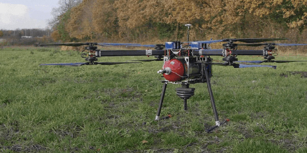
Fuel-Cell-Powered UAV Flies for 70 Minutes
There’s apparently a new way to overcome the short duration that is currently available for flying existing multi-rotor drones — don’t just rely on batteries, use hydrogen! Actually a hydrogen fuel-cell configuration that has recently been tested in the UK to extend flight time to 70 minutes, while carrying a 5-kg payload.
Test-drone with Intelligent Energy Hydrogen Fuel-Cell. (AVI screenshot supplied by Productiv)
The UK team includes Intelligent Energy, which supplies the fuel-cell, engineering firm Productiv, and UAS video company BATCAM, with funding provided by Innovate UK, a government-sponsored group that supports novel ventures such as this joint project.
Most existing battery-powered multi-rotor UAVs have endurance in the tens of minute (DJI seems to be approaching 20-30 minutes with some of its drone models). But longer endurance is really important for most operators, especially for capturing lengthy video, hence the interest and participation of BATCAM as the operator/consultant for the project.
Fuel cells provide a number of advantages over batteries with fast refuel, little vibration, quiet operation, zero emission at point of use, and around three times longer flight time. Intelligent Energy is making use of a portable hydrogen refueling system supplied by NanoSUN.
With BATCAM set to begin operational trials, the company is optimistic that further development of hydrogen fuel cells for UAVs will not only enable even longer video broadcasts but will solve the problem encountered with the difficult and expensive international transportation of Lithium polymer batteries.
Airship Moves towards Civil Certification
While we are in the UK, a huge 300-foot-long helium-filled airship called the Airlander 10 is again moving steadily down the path to gain civil approval by the Civil Aviation Authority (CAA), despite a previous crash in November 2017 due to a wayward landing cable.
The latest milestone was just achieved at the end of 2018 when CAA awarded Hybrid Air Vehicles Ltd. (HAV) a Production Organisation Approval, following on from earlier Design Organisation Approval by the European Aviation Safety Agency (EASA) in October 2018.
This behemoth airship is claimed to be the largest aircraft in the world, can carry 10 tons of cargo virtually anywhere on earth, stays airborne for up to five days, and can land almost anywhere. Powered by two forward-mounted rotating ducted fans and two aft fixed fans, all driven by diesel engines, the pressurized helium-filled envelope is 302 feet long, 143 feet wide, 85 feet tall, and has no internal support structures — all this with a cruise speed of up to 80 knots and a maximum altitude of 20,000 feet.
The Airlander is aimed at bulk cargo transport, but could also handle communication and observation/reconnaissance roles in both the military and commercial sectors. And it’s not so far away from becoming the largest unmanned aircraft in the world, either, should things eventually turn in that direction. Could there be potential for a greater payload without the extensive provisions for a pilot, with lower operating costs, potentially greater range and speed and/or operational altitude?
Miami Police use Tethered Aerostat
Miami police have been using a tethered aerostat to monitor large gatherings, such as the Dec. 28 Orange Bowl-related party called the Capital One Beach Bash. Presumably this use had a safety related motivation, and there was hopefully no intent to spy on partygoers.
However, I just became aware that police cannot fly drones in Florida to surveil people — there’s a law against it. But there is a provision in the Florida “Freedom from Unwarranted Surveillance Act,” which starts off: “If the law enforcement agency possesses reasonable suspicion that, under particular circumstances, swift action is needed to prevent imminent danger to life or serious damage to property,…”. Now, I’m no lawyer, but it would seem that this exclusion might possibly allow the Miami cops to monitor large gatherings where there might be a need to watch out for people’s safety – that generally being what we employ the police to do for us.
But the Florida lawmakers certainly believe that there is clearly a need to protect people’s privacy and to prevent unauthorized monitoring of an individual’s activities using drones. The provisions of Florida Statute 934.50 prohibits “the observation of such persons with sufficient visual clarity to be able to obtain information about their identity, habits, conduct, movements, or whereabouts” — a good thing to do to protect our freedom of movement and basic rights.
But you have to ask yourself if a general prohibition on the use of drones by police is the best thing to do when other police departments around the U.S. are gaining advantages from drone usage by speeding up and improving the accuracy of traffic accident investigations, for search and rescue, in crime scene reconstruction, for disaster response, and of course for improving officer safety — in fact, all the things that are already achieved through the use of police helicopters, but at a fraction of the cost.
Florida Statute 934.50 already has a significant number of allowable exceptions to enable a “law enforcement agency” and others to operate drones legally, but could it also be possible that these wider benefits of drone use might be fully exempted without infringing any personal liberties?
Conclusion
To sum up, we have a big aerospace company jumping in to help shape the future of unmanned air taxis; another drone fuel-cell application that significantly extends flight time; and progress towards certification of an airship that has benefits as a drone. Finally, police use of a tethered aerostat at an event stirs potential controversy, while other police forces benefit from the use of drones — a mixed bag of drone ventures that seem to have great potential.
Guest column by Peter Fairhurst, Director, Product Line Management, Product Center Positioning, u-blox
Peter Fairhurst, Director, Product Line Management, Product Center Positioning, u-blox. (Photo: u-blox)
A new generation of GNSS hardware and pioneering new correction data services are enabling cheaper, more compact and truly scalable high-precision GNSS solutions, ready for the mass market.
High-precision GNSS as employed by specialized markets for more than a decade isn’t aren’t suitable for mass-market autonomous vehicles or other mainstream use cases. As well as being big, heavy and expensive, traditional high-precision GNSS systems don’t scale, which is a critical shortcoming when you consider this capability may very soon need to be built into every car that gets built.
To overcome these challenges, we’re seeing two complementary things coming to market: a new generation of GNSS hardware, and pioneering new correction data services. These two key facets combine to enable cheaper, more compact and truly scalable high-precision GNSS solutions, ready for the mass market.
A new generation of GNSS correction service forgoes the two-way link between customer device and the correction data service that is a hallmark of traditional high-precision GNSS corrections. Instead of sending each device its own, location-specific GNSS correction data, the new-generation services create a real-time model of relevant errors across their entire territory. They broadcast this over satellite and/or the Internet for customer devices to pick up.
Transmitting modeled GNSS error data to receivers across an entire region – as opposed to maintaining a two-way link with each and every device – opens the door to large-scale, mass market applications of high-precision GNSS
The shortcomings of traditional high-precision positioning
Correction data has long been key to high-precision GNSS services. In traditional applications, the customer’s positioning device detects its approximate location and sends this information to its correction service provider. This provider uses a network of base stations to monitor GNSS errors, comparing the readings calculated from the satellite signals to the stations’ known, fixed positions. It uses these insights to send the customer’s device tailored correction data, based on its location.
The technology has successfully been used to provide centimeter-level accuracy in surveying, agriculture and machine control, but annual subscriptions of sometimes more than $1000 per device mean it’s remained confined to specialized markets.
Moreover, traditional correction data services typically only operate in one country, or even one state. While this may not be an issue in some applications (such as localized agriculture), there are other use cases where limited range is a major problem. Imagine, for example, that you regularly need to travel across a state or national boundary in your (semi-) autonomous vehicle, or carry out remote UAV-based surveying in another country: maintaining your high-precision positioning capability is likely to mean roaming contracts and other extra costs.
The other issue with these traditional services is scalability. They use two-way cellular communication to pass data back and forth between the customer device and the correction data provider. And while this works when device density is relatively low, if this number grew to thousands or even millions of end-user pieces of kit trying to access the correction data service, current cellular infrastructure would struggle to deliver the required reliability. Particularly in safety-critical applications, where losing access to the correction data service could put lives at risk, this is unacceptable.
Image: u-blox
Recent developments in high-precision positioning
The new generation of GNSS correction services, creating and broadcasting a real-time model of relevant errors across their entire territory, over satellite and/or the internet for customer devices to pick up, opens the door to large-scale, mass-market applications of high-precision GNSS. Technology using State Space Representation (SSR) is one flavor of these new-generation GNSS correction data services.
Japan has led the way in GNSS error-broadcasting, using the L6 signal of its QZSS satellite network as a proving ground for mainstream use of the approach. Although it’s currently only available within Japan, the Centimeter Level Augmentation Service (CLAS) is generating a lot of interest across the automotive, agricultural and machine-control industries. Mitsubishi Electric, for example, used the CLAS service to field-test its autonomous driving system.
In China, Qianxun Spatial Intelligence Inc. is pioneering a different technique. Instead of broadcasting the data, Qianxun SI is leveraging its special access to the Chinese GNSS reference base stations to push the boundaries of what’s possible using the traditional technique. It provides tailored correction data services to customers including individuals, system integrators and original equipment manufacturers (OEMs). While it’s been a success in China, the approach is less appealing to OEMs who ship worldwide, because it requires their clients to arrange their own, local GNSS correction data.
Another important advance has been the rise of multi-band GNSS receivers, which enhance standalone positioning accuracy, thereby delivering a better customer experience in a variety of use cases. However, even multi-band receivers can’t achieve the centimeter-level accuracy that mobile robotics and autonomous vehicles need: these devices will always need to be complemented by some form of correction service.
Continent-wide GNSS correction data
Particularly in Europe, where there’s a lot of cross-border travel and economic activity, the simplicity of continent-wide GNSS correction services would offer enormous value. Sapcorda, for example, a recently launched joint venture between Bosch, Geo++, Mitsubishi Electric and u-blox, is creating a next-generation GNSS correction data service with coverage on a global scale (Europe, North America, etc), building on the lessons learned in Japan.
Sapcorda will broadcast right across the continent, using cellular networks as well as over satellite links. Customers won’t be tied to a specific GNSS manufacturer. Data will be distributed in an open format, so that device-makers can create exactly the solutions their customers want.
Having access to GNSS correction services continent-wide has the potential to transform high-precision positioning into a mainstream offering, supporting various IoT applications, as well as drones and (semi-) autonomous vehicles.
Addressing the remaining challenges
High-precision GNSS correction services that target the mass market are still relatively new, with different suppliers pursuing different business models. Trimble’s service, for example, doesn’t use an open correction-data format, and is only compatible with devices using its own GNSS receivers. The benefit of this is that it can deliver a seamless, fully integrated solution, with complete interoperability across the Trimble product range (provided the region in question has good coverage). OEMs with customers is geographically broader markets will need to weigh this up against the benefits of global coverage provided by a range of correction-data suppliers offering open-format data.
As we touched on earlier, in safety-critical applications where location-accuracy is essential, any correction data service must be up to the task. This includes ensuring data broadcasts aren’t crowded out when cellular networks become saturated. To this end, u-blox has been working with the 3GPP body to create appropriate standards that can ensure the service meets the required service level agreements.
Lastly, although there’s now country-wide coverage in both China and Japan, Sapcorda is now attempting to provide continent-wide high-precision services. If it’s a success, it could overcome the challenges of national boundaries and country-based cellular providers. It’s as yet unclear how existing correction-data-service suppliers will respond.
Customer satisfaction is paramount
For high-precision GNSS services to achieve mainstream success, they not only need to offer wide coverage and be truly open, but must facilitate innovation and ensure they can broaden the appeal of this capability beyond being a niche specialism. Like in any industry, customer satisfaction is essential if the technology is to achieve this.
Complexity that arises as a result of state boundaries, national borders, conflicting regulations or subscriptions, must be shielded from the end user and dealt with upstream. This is already happening in some areas, where device-makers are partnering with correction data service providers, enabling them to bundle the service cost into the device cost that the end user pays.
A revolution in positioning
As well as helping to realize some of the automated navigation solutions currently under development, new-generation high-precision GNSS services are driving a seismic shift across the whole industry.
The rise of innovative, high-precision GNSS technology, combined with business models that promise to make high-precision a mass market reality, mean the coming years will be tremendously exciting. By disrupting the existing market, the new technology will mean lots of new opportunities for those ready to grasp them.
Peter Fairhurst joined the Product Strategy team in the Product Center Positioning at u-blox AG in 2015. He is responsible for the development of industrial markets, with a specific focus on unmanned systems and mapping solutions. Prior to u-blox, he was part of the Product Management group at Leica Geosystems AG, where his focus was on high-precision GNSS surveying technology.
Fairhurst holds a bachelor degree in Mathematics & Computer Sciences and doctorate degree in satellite geodesy from Newcastle University and an MBA diploma from the University of Strathclyde.
Bell Helicopter unveiled a full-scale vertical-takeoff-and-landing (VTOL) air taxi vehicle during CES 2019, held in Las Vegas.
The air taxi, named Bell Nexus, is powered by a hybrid-electric propulsion system and features Bell’s signature powered lift concept incorporating six tilting ducted fans designed to safely and efficiently carry passengers.
Bell Nexus means the nexus of transport and technology and of comfort and convenience. Nexus captures the long-sought-after vision of quick air travel with a unique in-flight experience, keeping passengers connected to their lives and saving valuable time.
The Nexus team consists of Bell, Safran, EPS, Thales, Moog and Garmin, who are collaborating on Bell’s VTOL aircraft and on-demand mobility solutions. Bell is leading the design, development and production of the VTOL systems; Safran is providing the hybrid propulsion and drive systems; EPS is providing the energy storage systems; Thales is providing the Flight Control Computer (FCC) hardware and software; Moog is developing the flight control actuation systems; and Garmin is integrating the avionics and the vehicle management computer (VMC).
Autonomous Pod Transport (APT). Alongside the debut of Bell Nexus, Bell will feature the Autonomous Pod Transport (APT). The APT family varies in payload capability that can serve many mission sets such as medical, law enforcement, offshore missions and on-demand delivery services. Bell is expanding into a new industry to show the full spectrum of our capabilities and the real-world challenges APT will address, Bell said in a press release.
Future Flight Controls. Bell’s Future Flight Controls simulator was a new experience for CES participants this year. Bell is actively collecting data to help shape the future flight controls of aviation. Data from the simulators will be used to determine what actions and interfaces are intuitive to the average potential operator and what prior experiences and abilities contribute to these opinions.
Urban air travel is coming closer to the masses through recent advancements in technology and software. The critical last step is designing a flight-control ecosystem that allows individuals to safely and efficiently operate urban air vehicles.
In 2018, Bell provided the world a glimpse into the air-taxi passenger experience, and this year, attendees could see the full vision.