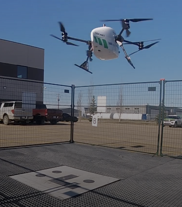
The Trimble module provides Volatus’ clients with a turnkey solution for highly-accurate aerial data acquisition and fully-remote drone operations in real-world missions, including beyond visual line of sight (BVLOS).
The Trimble PX-1 RTX uses Trimble’s CenterPoint RTX corrections along with compact, high-performance GNSS-inertial hardware to deliver real-time, centimeter-level positioning and highly precise inertial-derived true heading measurements. This technology reduces operational risks associated with poor sensor performance or magnetic interference by providing enhanced positioning redundancy.
Volatus must meet strict guidelines addressing airspace entry and exit, altitude and speed, and communication and remote identification when taking off from and landing at the Edmonton International Airport in Alberta, Canada. The flight corridor approved by Transport Canada and Nav Canada requires them to land and takeoff with precision, while staying at 50-feet altitude when crossing airplane arrival routes.
Trimble PX-1 RTX’s precise positioning capabilities address crucial accuracy challenges for takeoff and landing, while supporting an exact flight altitude and positioning within the flight corridor. This capability enaables Volatus to remain compliant with the controlled airspace authorization from Nav Canada, a non-profit that operates the country’s civil air navigation system.
The Trimble PX-1 RTX solution is available through Trimble sales channels.
Transport Canada has issued a Special Flight Operations Certificate (SFOC) to Volatus Aerospace Inc., authorizing the company to conduct beyond visual line of sight (BVLOS) drone operations using MatrixSpace’s radar technology integrated with Kongsberg Geospatial’s IRIS Terminal platform.
The certification allows Volatus to use MatrixSpace‘s compact, low-power radar system that can detect smaller aircraft including other drones. The technology is integrated with Kongsberg’s airspace awareness software and operated through Volatus’ remote Operations Control Center.
The system enables automated drone-in-a-box networks, distributed monitoring operations and autonomous services that require continuous detect-and-avoid capabilities. Market research indicates the global drone-in-a-box sector was valued at approximately $1 billion in 2024 and is projected to reach $5 billion to $9 billion by the early 2030s, representing annual growth rates of 20% to 23%.
Volatus previously held nationwide SFOCs for BVLOS operations in low-risk airspace, atypical airspace, high-altitude missions and nighttime operations. The new certification expands the company’s ability to provide automated drone services for infrastructure security, utilities monitoring, industrial inspection, forestry operations, wildfire monitoring and environmental oversight.
The company has previously conducted approved BVLOS medical delivery operations at Halton Healthcare in Ontario. According to the comapny, the new certification builds on those capabilities by incorporating the detect-and-avoid system for broader commercial deployment.
Launched in 2003, Canada’s Precise Point Positioning (PPP) service, CSRS-PPP, continues to solidify its place as a world-class GNSS post-processing platform. Operated by the Canadian Geodetic Survey (CGS) under Natural Resources Canada (NRCan), the service enables users to obtain highly accurate coordinates from raw GNSS data without requiring proximity to a base station. Users simply upload RINEX observation files from either static or kinematic receivers, and CSRS-PPP returns positions referenced to NAD83(CSRS) or the International Terrestrial Reference Frame (ITRF). Crucially, this free and publicly accessible service is contributing enormously to the democratization of centimeter-level GNSS positioning for users around the world.
Galileo PPP-AR Now Supported
On May 14, 2025, CGS released a major upgrade to the service that introduced support for GalileoPPP with Ambiguity Resolution (PPP-AR). This new capability applies to Galileo E1/E5a signals recorded on or after November 27, 2022, and is available when using either Rapid or Final products. These “products” refer to high-precision satellite data; specifically, calculated information about satellite orbits, clock corrections, and signal biases, based on data collected by a global network of stations. The collected data are processed by NRCan and international partners to support CSRS- PPP’s precise positioning outputs. The recent CSRS-PPP upgrade builds on the PPP-AR support for GPS added in 2020 for data recorded on or after January 1, 2018, marking a significant step toward fully integrated, ambiguity-resolved positioning using data from multiple GNSS constellations.
Why PPP-AR Matters
The major milestone in October 2020, when ambiguity resolution was introduced to the CSRS-PPP platform, ushered in a new era of precision for users. At the core of PPP-AR is a significant shift in how satellite signals are interpreted. Traditional PPP estimates carrier-phase ambiguities as ‘float’ (real-valued) parameters because the integer number of whole carrier wavelengths between satellite and receiver remains unknown and unresolved. In contrast, PPP-AR resolves these ambiguities as fixed integers by utilizing precise satellite orbit and clock products alongside detailed modeling of satellite and receiver biases, thereby enabling reliable integer ambiguity resolution. This leap in algorithmic refinement leads to faster convergence times and enhanced accuracy, often down to the centimeter level. Ambiguity Resolution can lead to particularly noticeable improvements on east–west accuracy, which makes PPP-AR particularly valuable in applications demanding high horizontal precision.
CSRS-PPP Advances: Broader Satellite Support and Richer Output Data
Since its inception, CSRS-PPP has evolved steadily. Alongside expanded satellite constellation support, the platform’s reference frame has progressively advanced through updates from ITRF2005 to subsequent realizations, culminating in the adoption of ITRF2020. Additionally, CSRS-PPP output files now include valuable metrics such as estimated tropospheric delays, receiver clock offsets, and ambiguity resolution statistics. These enhancements provide users with more detailed insights into solution quality.
Meeting Growing Demand
Canada’s geodetic services continue to experience strong growth, with an increasing number of users relying on the CSRS-PPP service and related geodetic tools for essential positioning information. According to the Surveyor General Branch Annual Report for 2022–2023, file retrievals through CSRS-PPP and related tools increased by 45% in 2022 compared with 2021. Between 2022 and 2023, CGS supported over 11,000 active users and processed close to 1.3 million files across its suite of geodetic products and services.
An Evolving Platform
Even as this article was being written, on July 15, 2025, CSRS-PPP announced support for GPS signals C1L, L1L, C1X and L1X, further enhancing its capabilities and reaffirming its role at the core of a modern geodetic infrastructure. As GNSS shifts toward multi-frequency, multi-constellation services, CSRS-PPP is evolving in parallel, making centimeter-level accuracy accessible to a wider user base. With robust algorithms and enriched data outputs, CSRS-PPP remains a critical tool for high-precision positioning in Canada and a model for international GNSS services.
Canadian scientists recently led their first Antarctic research expedition, using Montreal-made Arrow Gold+ GNSS technology for precise location data in remote and challenging conditions. The mission, which departed in early March 2025 aboard HMCS Margaret Brooke, included experts from multiple Canadian universities and government agencies. Researchers conducted water, sediment, air, and sea-ice sampling to study climate change, glacial retreat and pollution such as mercury and microplastics.
The month-long journey around the South Shetland Islands and the northern Antarctic Peninsula yielded surveys of coastal and oceanic sites. The crew relied on a small, unmanned surface vessel (USV) carrying various equipment for bathymetric surveys including an onboard computer, IMU and multibeam sonar.
In order to find the USV’s precise position in an environment with no land-based RTK infrastructure, the team relied on the Arrow Gold+ GNSS receiver, designed and manufactured by Canadian-based Eos Positioning Systems. The Arrow Gold+ utilized Galileo High Accuracy Service (GalHAS), a free satellite-based PPP correction available worldwide from the European Union’s Galileo Programme.
“There aren’t any RTK networks in Antarctica,” said Kevin Wilcox, Ocean Mapping Group research scientist, who piloted the USV. “That sent us looking for the Arrow Gold+ and GalHAS corrections. When we found these, we realized we had a possible solution.”
While using GalHAS corrections, the Arrow Gold+ provided estimated accuracies of about 10 cm horizontal and 15 vertical to 20 vertical.
“The vertical accuracy was especially important for our bathymetric work,” Wilcox said. “Any vertical error would directly add error to our depth.”
Sites surveyed include Admiralty Bay, Livingston Island and Deception Island, which includes an active, flooded volcano caldera. The resulting, high-accuracy maps will support further scientific and oceanographic research, environmental monitoring, and improvements to marine charts.
By adding high-accuracy locations with an average accuracy of 10 cm to 20 cm horizontal and vertical, the team was able to accurately georeference and further refine the detail of the bathymetry for their map inside the underwater Deception Island caldera. (Photo: Eos Positioning Systems)
Eos Positioning Systems (Eos) has become a member of the Municipal Information Systems Association (MISA) Canada’s National Partner Program (NPP). This collaboration aims to enhance the capabilities of Canadian municipalities in utilizing GNSS technology for improved mapping and asset management.
The partnership between Eos and MISA Canada facilitates the digital transformation of Canadian cities and towns by bringing together municipal leaders and technology innovators. Eos specializes in providing high-accuracy GNSS technology to local governments, enabling them to maintain critical infrastructure and public services more effectively.
Eos manufactures GNSS receivers in Canada that offer submeter to centimeter-level accuracy for GIS and mapping applications. These tools are particularly useful for utility and infrastructure mapping, public works asset management, environmental monitoring and planning and emergency response coordination.
The GNSS receivers from Eos are designed to integrate with existing GIS software and mobile devices, allowing field teams to efficiently collect, update, and manage spatial data with high precision. As part of MISA’s NPP, Eos will provide members with access to specialized solutions, training resources, and ongoing technical support to maximize the benefits of GNSS technology in municipal operations.
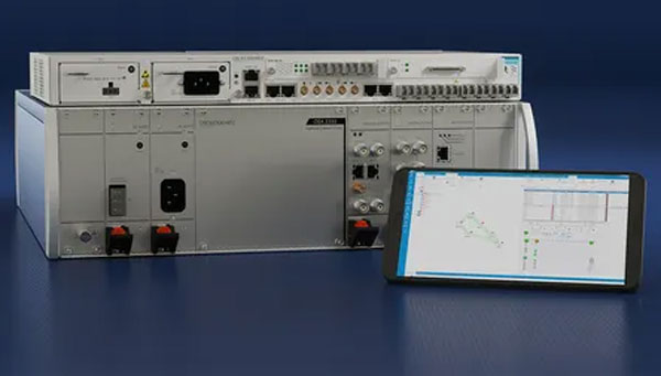
A leading Canadian hydropower producer is using the Adtran Oscilloquartz grandmaster device combined with its optical cesium atomic clock to achieve new levels of precision, reliability and resilience in its power grid synchronization network.
The deployment addresses the urgent need to implement the highest standards of protection against GNSS disruptions — including jamming and spoofing cyberattacks — and helps bolster North America’s energy resilience. Featuring multi-source protection, the enhanced timing architecture offers a zero-trust approach to positioning, navigation and timing (PNT), ensuring robust and accurate synchronization. It also seamlessly supports existing services, which allows for a smooth transition from legacy timing to power grids with advanced PTP technology. For streamlined operations and assurance, the synchronization network is remotely managed through the Adtran Ensemble Controller with Sync Director.
By enhancing its timing framework with Adtran’s Oscilloquartz solution, the hydroelectric producer is designed to maintain the highest standards of cybersecurity and energy reliability in its critical infrastructure, the company said. The deployment aims to improve the stability and security of the energy supply across Canada and the United States.
The new solution includes Adtran’s OSA 3350 ePRC+ combined with the OSA 5422 to provide precision, stability and resilience against GNSS vulnerabilities. It has an all-digital design, which utilizes optical-pumping techniques, to guarantee timing accuracy and optimal stability for over a decade. This is twice the lifespan of conventional cesium clocks.
With the OSA 5422, the solution future-proofs the utility’s timing network and assures compliance with governmental regulations. It fortifies security and underscores the renewable energy utility’s commitment to maintaining a continuous, secure power supply.
It is no secret that the world has been burning for months. Devastating wildfires have encompassed Greece, Canada, the United States, and other parts of the world. These wildfires have incinerated entire communities, taken lives, and has had disastrous environmental effects. This wildfire outbreak can be attributed to several factors, but mainly the global climate crisis.
Why are these wildfires a monumental problem?
Widespread wildfires displace of thousands of people from their homes, raze entire communities and cities, wipe out farmland and other essential resources, create horrific air pollution — that causes inflammation of lung tissue and increases vulnerability to infections — and many other devastating effects.
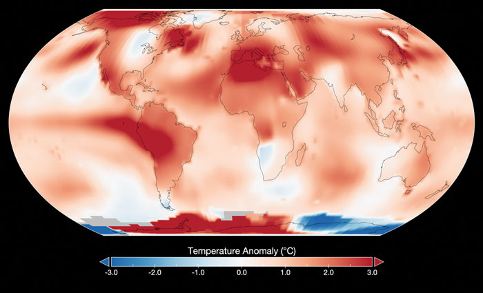
Image: NASA
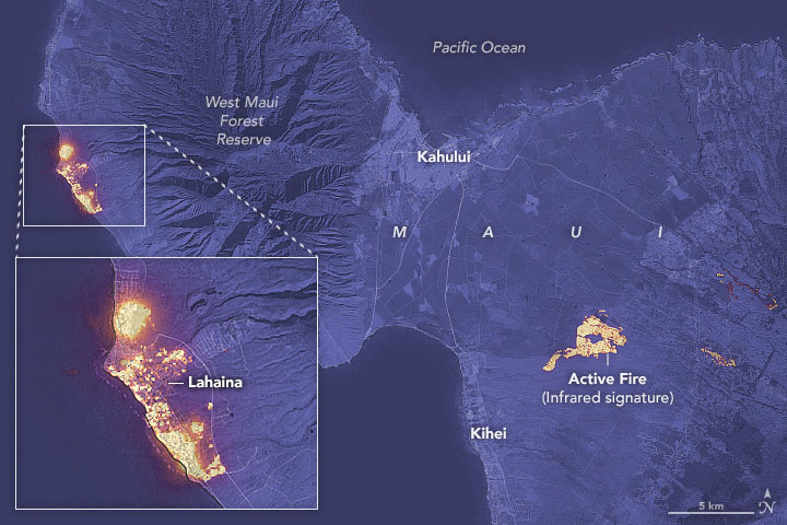
As reported by NASA, July has been the hottest month on record since the 1880’s. This has caused extreme dry conditions that are ideal for wildfire outbreaks, among other natural disasters.
Image: NASA
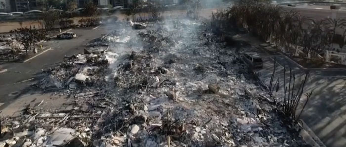
Flames engulfed parts of Hawaii the morning of Wednesday, August 9, which destroyed a centuries-old town and killing at least 106 people as of August 16. The wildfires took natives and tourists on the island by surprise. Residents and tourists were forced to evacuate the area – including some who reportedly jumped into the ocean to escape the flames. The National Weather Service stated the combination of high winds and low humidity is what caused the dangerous fire conditions across the island. The devastating fire left behind burned-out cars on once busy streets and smoking piles of debris where historic buildings once stood.
Image: Screenshot of BBC video
The Greece wildfires swept across the island of Rhodes, Corfu and Evia in July, creating thick clouds of smoke and forcing thousands of people the evacuate. These fires were caused by several human imposed factors such as campfires, arson and sheer negligence. However, the deadly heatwave that scorched Europe this summer — caused by carbon emissions — has not helped prevent the start and spread of these wildfires.
The Air Quality Index (AQI) measures the density of five pollutants: ground-level ozone, particulates, carbon monoxide, nitrogen dioxide, and sulfur dioxide. It was originally established by the Environmental Protection Agency to communicate the cleanliness of the air Americans are breathing every day. The index runs from zero to 500 — the higher the number the more polluted the air is. Effects of air pollution can range from mild symptoms, such as eye and throat irritation, to serious ones such as heart and respiratory issues. Pollution can cause inflammation of the lung tissue and increase the vulnerability to infections.
During wildfires, fine particles in the soot, ash and dust can fill the air.The AQI identifies the concentration of particles smaller in diameter than 2.5 μM. When these particles are inhaled, the tiny specks can increase the risk of heart attacks, cancer, and respiratory infections — especially in children and older adults.
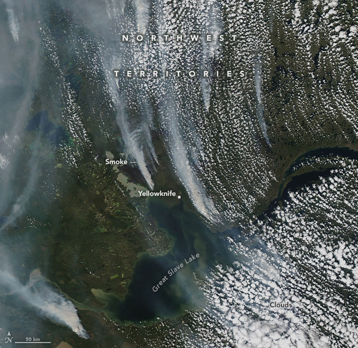
Image: NASA
Based on data from the Canadian Interagency Forest Fire Centre, there are 1037 active fires in Canada: 652 are out of control, 161 are being held in place, and 224 are under control as of August 23. Many of these fires were caused by lightning; however, with above-average temperatures this year and dry conditions, wildfires have been breaking out in Canada since May.
Wildfires have recently spread across Greece, Italy, Spain, Portugal, Algeria, Tunisia and Canada, causing mass environmental and economic damage as well as human casualties. Scientists have warned that wildfires are becoming more frequent and more widespread.
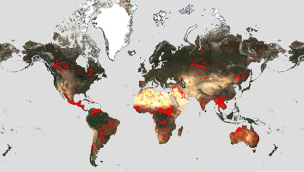
In response, an upgraded version of the World Fire Atlas from the European Space Agency (ESA) is now available. The atlas provides a detailed analysis and map of wildfires across the globe.
Rising global temperatures and the increased extreme weather has led to a surge in the number of wildfires rapidly consuming extensive areas of vegetation and forested lands.
Considering the severe wildfires, ESA has reopened its World Fire Atlas which offers an insight into the distribution of individual fires taking place at a global scale.
Through its interactive dashboard, users can compare the frequency of fires between countries as well as analyze the evolution of each wildfire taking place over time. The atlas was first available in 2019 and it supported both European civil protection agencies and firefighters.
The dashboard uses night-time data from the sea and land surface temperature radiometer (SLSTR) on board the Copernicus Sentinel-3A satellite. Working like a thermometer in the sky, the sensor measures thermal infrared radiation to take the temperature of Earth’s land surfaces which is used to detect the fires.
Data from the Copernicus Sentinel-3B satellite will be added to the atlas in December.
Over the previous seven years, data from the World Fire Atlas show a substantial number of fires detected in Portugal, Italy, Greece, France and Spain.
Data also shows that Canada has experienced 11,598 fires during the first seven months of this year alone. This is a 705% increase compared to fires detected over the same period of the previous six years. Canada is currently battling the country’s worst wildfire season on record, with more than 10 million ha of land burned, which is said to increase in the coming weeks.
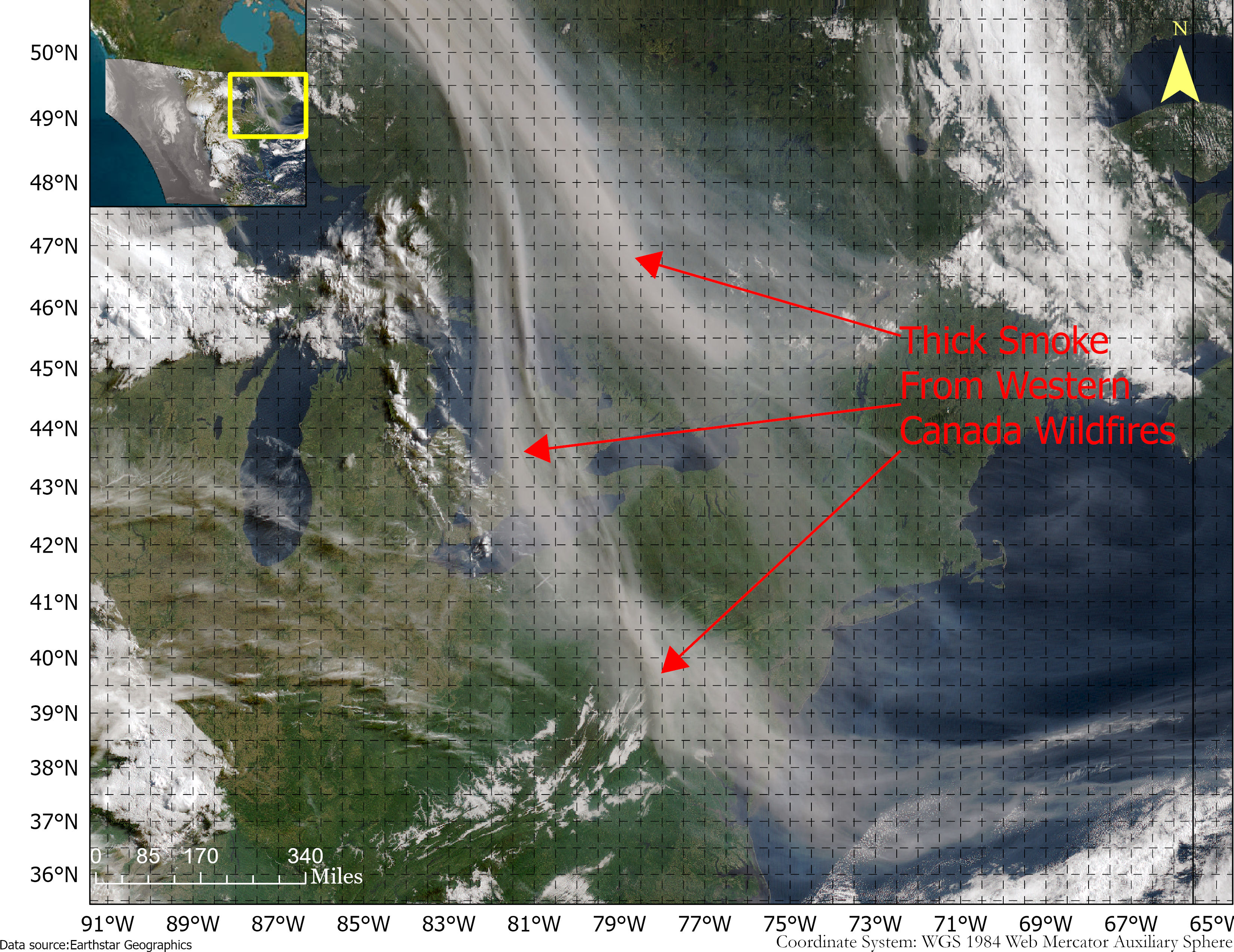
Smoke from the Canadian wildfires continues to pollute the air across the United States, mainly affecting cities in the northeast, including Pittsburgh, Chicago, Cleveland, Detroit and Buffalo.
According to the New York Times, in early June, the level of particulate matter in the air from smoke became so unhealthy that many U.S. cities set records. Visibility decreased in many cities as well, with the smoke creating an orange haze.
Most of the smoke can be attributed to several fires burning across Canada. Many of these fires were caused by lightning; however, with above-average temperatures and dry conditions, wildfires have been breaking out since May.
A storm system off the coast of Nova Scotia forced smoke from the fires southeast into the United States. (Image: NOAA)
Based on data from the Canadian Interagency Forest Fire Centre, there are 480 active fires in Canada: 252 are out of control, 77 are being held in place, and 151 are under control.
The fires are mapped in the image below.
The red dots represent the out-of-control fires, the green dots are fires being held in place, and the yellow dots are fires that are under control. (Image: Screenshot of CIFFC wildfire map)
Understanding air quality importance
The Air Quality Index (AQI) measures the density of five pollutants: ground-level ozone, particulates, carbon monoxide, nitrogen dioxide, and sulfur dioxide. It was originally established by the Environmental Protection Agency to communicate the cleanliness of the air Americans are breathing every day.
The index runs from zero to 500 — the higher the number the more polluted the air is.
Effects of air pollution can range from mild symptoms, such as eye and throat irritation, to serious ones such as heart and respiratory issues. Pollution can cause inflammation of the lung tissue and increase the vulnerability to infections.
During wildfires, fine particles in the soot, ash and dust can fill the air.
The AQI identifies the concentration of particles smaller in diameter than 2.5 μM. When these particles are inhaled, the tiny specks can increase the risk of heart attacks, cancer, and respiratory infections — especially in children and older adults.
Below is an updated map of air quality from the U.S. AQI as of June 28.
The colors on the map range from yellow — which is unhealthy air quality — to purple, meaning the air quality is hazardous. (Image: AirNow.gov)
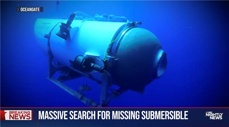
OceanGate. (Credit: Screenshot of NBC news coverage)
On June 17, an OceanGate Expedition Titan submersible launched off the coast of Newfoundland, Canada, carrying five passengers to the bottom of the Atlantic Ocean to explore the infamous R.M.S. Titanic shipwreck. The U.S. Coast Guard said that the submersible lost contact with the surface vessel about an hour and 45 minutes after the launch and has not been in contact since.
The submersible can support life for 96 hours. As of the afternoon of June 20, it had 40 hours of oxygen left and U.S. and Canadian agencies were still searching for it.
The Titan submersible explained
According to the OceanGate website, the Titan is “a Cyclops-class manned submersible designed to take five people to depths of 4,000 [m] (13,123 [ft]) for site survey and inspection, research and data collection, film and media production, and deep-sea testing of hardware and software.” The Titan is equipped with an inertial navigation system (INS), an ultra-short base line acoustic positioning system, a robotics laser scanner, a Teledyne 2D sonar and more.
While it is equipped with an INS, the Titan relies on messages from a surface ship to guide the submersible to the shipwreck. The submersible and surface vessel rely on Elon Musk’s Starlink satellites for communication.
A part of the Titan worth mentioning, the crew is sealed inside and bolts are applied to the outside — needing an external crew to remove them upon surfacing.
Foreshadowing
The New York Postreported, in 2022, that an OceanGate Expedition to the Titanic lost contact for more than two hours and never found the wreck.
Aboard the submersible was a CBS correspondent, David Pogue, who was filming a segment for CBS Sunday Morning. He tweeted about the incident.
There are 18 planned expeditions to the Titanic with OcenGate Expeditions to survey the shipwreck, collect data, and document high-resolution images and videos.
The entire trip to the Titanic wreck site takes 8 days, and one dive can take up to 10 hours. The expedition is comprised of five legs.
For tough shots in complex construction sites, Lee Landman says that tilt make impossible shots possible. (Image: Lee Landman)
Prior to the advent of tilt compensation for surveying and construction GNSS rovers, there were incremental approaches to tilt, with limited success. However, five years ago, “no-calibration tilt compensation” was first incorporated as a standard option for rovers. Some users remain skeptical or exercise the same caution as they did when such innovations as EDMs were first introduced. Nevertheless, the adoption of tilt compensation — for appropriate tasks — has spread rapidly. How did we get to this point?
For centuries, plumb bobs and bubbles were the only viable options to level an instrument or pole about a point. Early references to spirit levels appeared in the 15th century; however, siphon style water levels may have been in use in ancient Greece, China, and elsewhere for much longer. In more recent centuries, various types of level vials became a standard feature for surveying transits, theodolites and levels. Vials with a slight upward curve position a bubble between defined center marks when level.
Circular, convex glass bubbles appeared for industrial applications in the 19th century and were soon incorporated into surveying instruments and survey poles. In recent decades, electronic bubbles, or “e-bubbles” emerged, using microelectromechanical (MEMS) tilt sensors along with various methods to apply an orientation to compute the position of the pole tip relative to the phase center of the GNSS antenna. This is in contrast to relying on a bubble alone to orient the phase center directly above the pole tip.
There are both pitfalls and potential productivity losses if the pole has to be leveled solely with a bubble for each measurement; we’ll examine these later. If freed from the bubble — as electronic bubbles, tilt sensors, and various methods for orientation enable — how much productivity gain can be realized? For which tasks do the users find tilt compensation most useful? For which do they not? We talked with manufacturers, dealers and field users to find out.
Early adopters
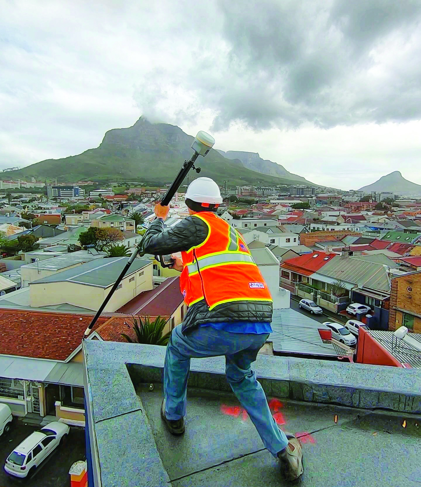
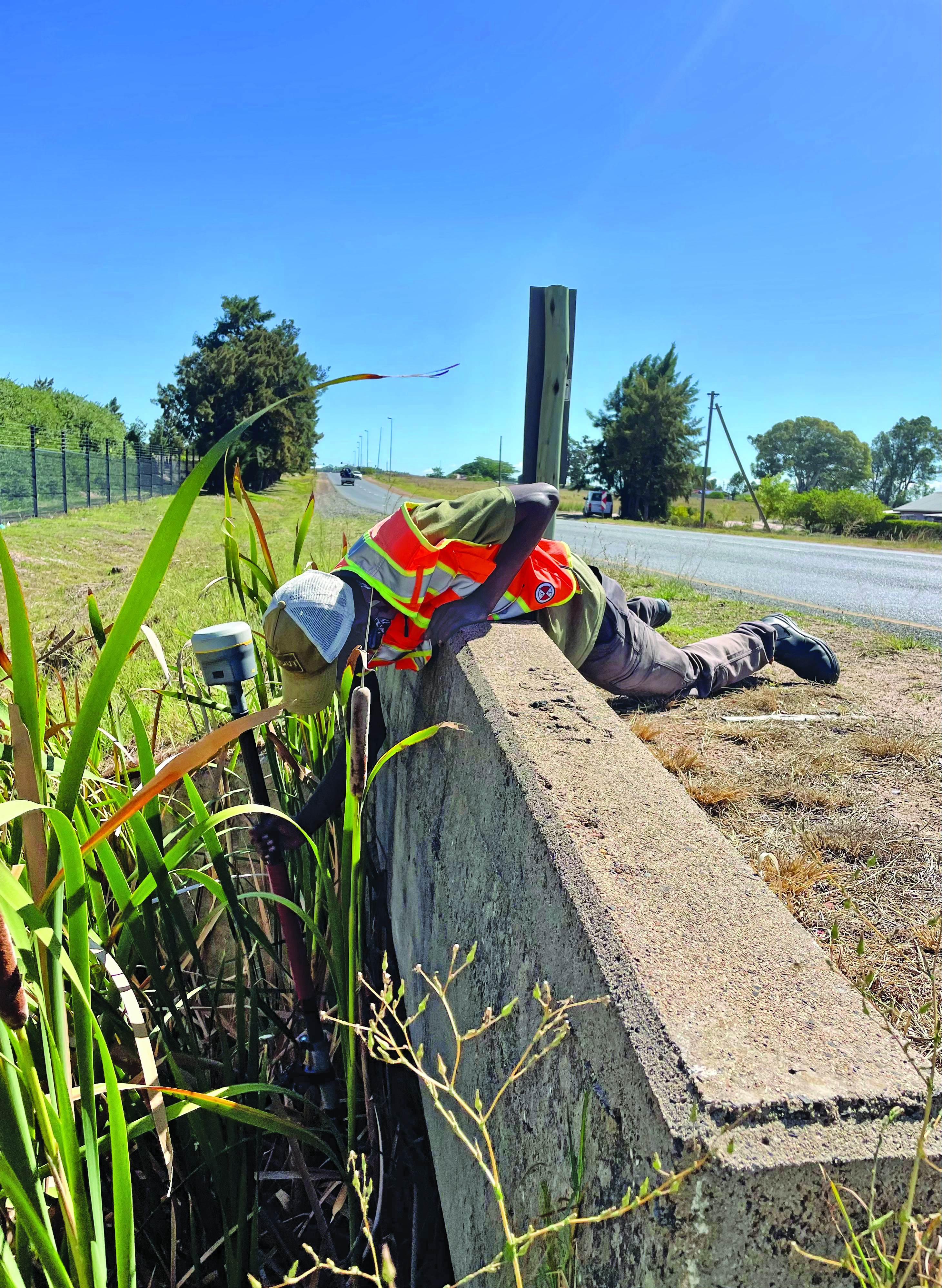
Tilt for safer surveying. (Image: Lee Landman)
Lee Landman owns a firm in the Cape Town area of South Africa that provides construction layout, civil engineering layout and related topographic mapping services. Landman obtained a Trimble R12i GNSS rover, with no-calibration tilt, shortly after its release in 2020.
“Tilt is my go-to tool for almost all tasks now, except layout that needs better than 15 mm to 20 mm tolerance,” Landman said. “For topographic mapping, I will get everything possible with tilt, and then use a total station to get the points I can’t with the rover.”
Landman reports productivity gains of 30% to 50% on certain jobs. His crews will try to leverage a tilt rover for as much of a job as they can, provided it meets precision needs. For checking work, such as grade checking or layout verification, they will try to use tilt for everything first. Then in any areas that look suspect, they will set up a total station to confirm. He said this saves a lot of time up front.
After several years of use, Landman said there are specific tasks where they will not use tilt, and we find this echoed by other users interviewed (and from my own tests). For instance, construction layout of such structures as walls and columns where a consistent 5 mm to 10 mm tolerance is required. He said the same applies for tasks where precise elevation is key, such as on road curbs and final road levels. However, he noted: “That’s a GNSS precision thing, not a tilt issue.”
Landman provides other caveats,“I am nervous using tilt on long rods or when you constantly change rod height, as the results of using a wrong rod height would be disastrous, and the deflection on long rods could also degrade the results.”
Summarizing the overall impact on his operations, Landman explained, “We have become more competitive. Not by sharpening our price, but by the fact that using tilt is less fatiguing and faster to do layout and data collection. That gives us an edge over firms that are not using it.” He provided the example of a foundation layout that needed 300-400 points laid out and chalked in an hour or two so that the excavators that were standing by could start digging as soon as possible. “It normally takes two to three moves of the pole and bubble checks to get a point on position without tilt,” Landman said. “Now, when you are doing 300 points, that is 600-900 times that I don’t have to look at the bubble and adjust the rod. The amount of energy and fatigue that saves is just outstanding. No sore lat muscles and eye fatigue.”
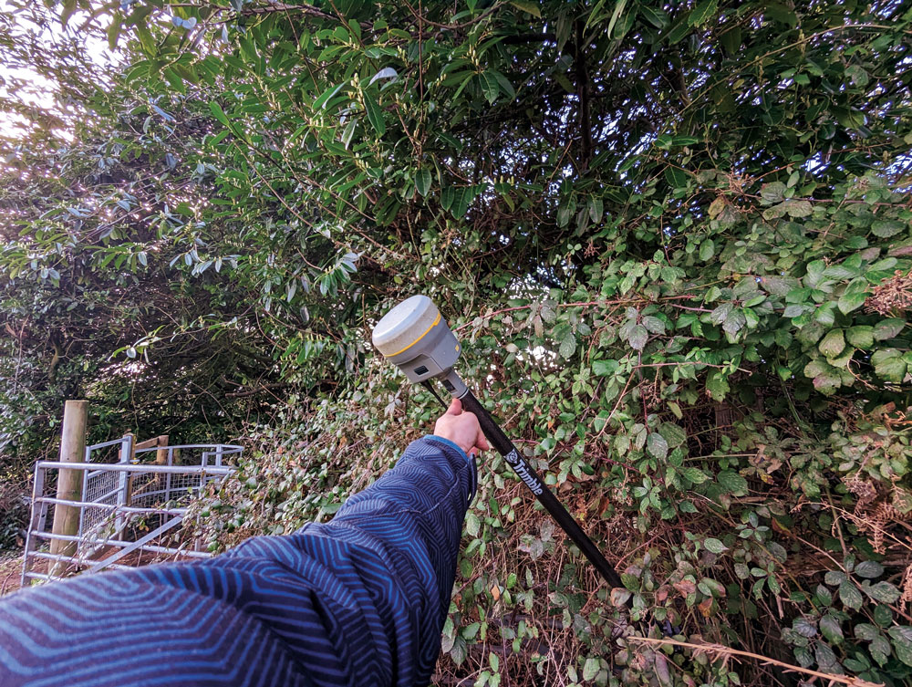
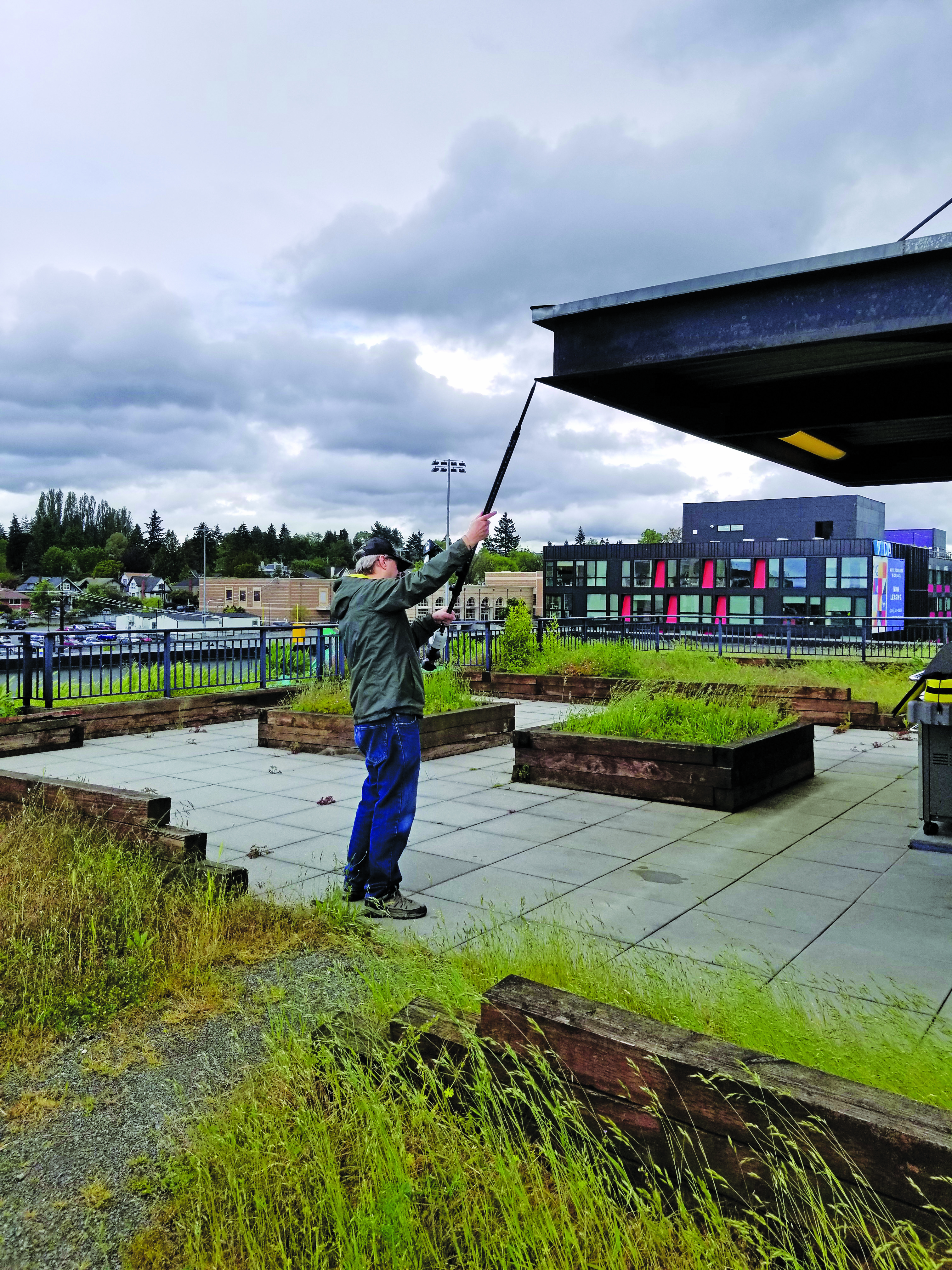
In the southwest of England, where Benchmark Surveys operates, fields and roadways are often lined with thick brambles, making if difficult to shoot features underneath them, such as utilities. James Richards of Benchmark says tilt has revolutionized the way they survey, enabling shots in places where even a total station (where the rod needs to be plumb) cannot take them. (Image: Benchmark Surveys)
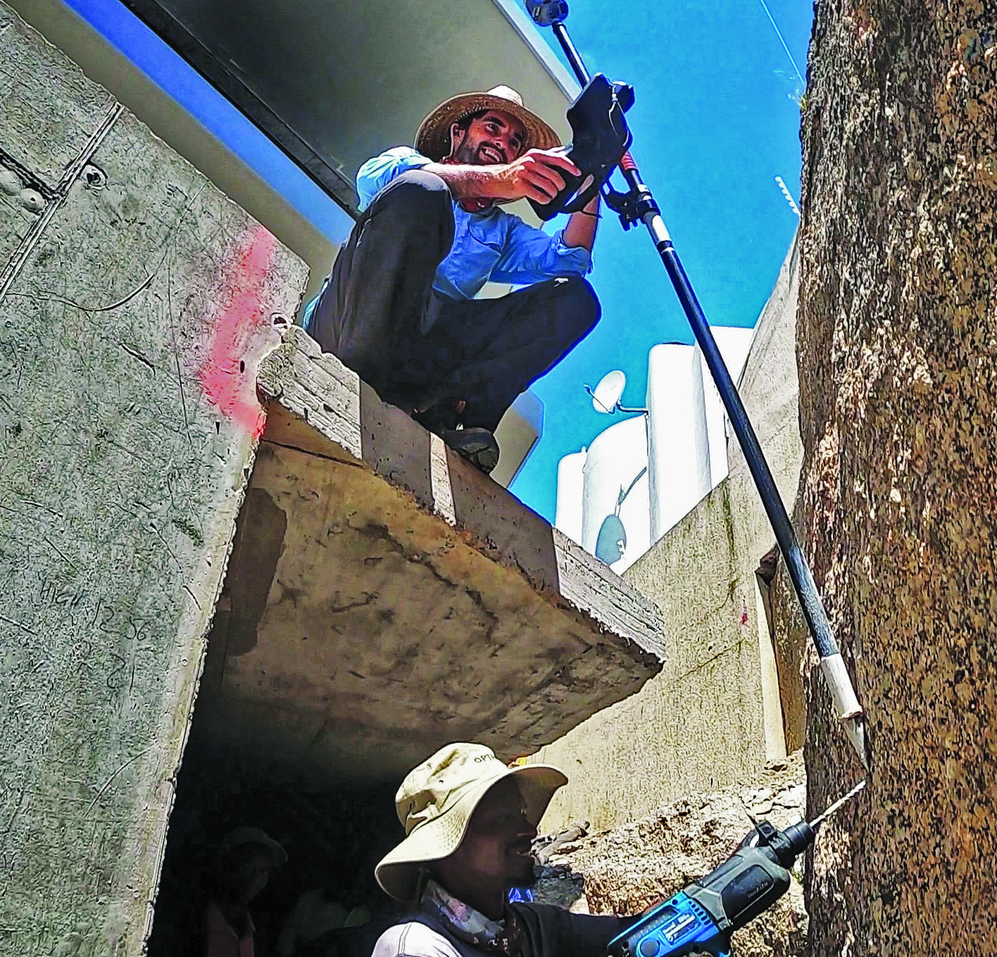
Then there are shots that you cannot get with a bubble plumbed pole, Landman said. For instance, in checking rebar layouts prior to construction, as well as marking out on or below the steel rebar cages for plumbing points, voids and slab penetrations.
“Previously we could not easily do this, as you cannot get the pole plumb for total station shots or GNSS to place or check a point,” Landman said. “You just have to check positions on the steel for a column or wall to see if it has enough concrete cover or is in the right position prior to pouring concrete.”
James Richards is the survey manager for Benchmark Surveys, a family-owned and operated firm in the southwest of the UK that has steadily grown its portfolio of services. In part, this growth has resulted from their willingness to embrace new and emerging technologies. This included adding tilt compensated R12i rovers to their instrument inventory shortly after they became commercially available.
“We use tilt on every surveying task where we can use GNSS,” Richards said. “Tilt has enabled us to complete numerous jobs where we would have otherwise only been able to use a total station.” Apart from control, there are not many tasks for which Richards would not recommend using tilt, “It has helped improve our surveys. We can capture data quicker and easier than before and with greater accuracy.” Examples of daily challenges his crews face include getting shots in and around ditches, field boundaries, and boundary fences in foliage, and walls with foliage overhang. These are now easily captured using tilt.
“Tilt has had an enormous impact on our business. We complete work to a higher standard, capturing data quicker and easier,” said Richards. “It helps us capture data that was not possible without offsets. We’ve seen a rise in profitability since using tilt. Surveyors seem to be happier with day-to-day work, knowing that they can capture the data required to meet our high standards, and clients are also happier when receiving more data than expected from surveys.”
Stages of adoption
CHC Navigation is a GNSS developer and manufacturer that has sold hundreds of thousands of units over the past 15 years. They were quick to develop and implement tilt compensation technology, which has now become standard on all of their current models.
Rachel Wang, product manager of CHC Navigation’s Surveying and Engineering division explained the four stages they undertook in developing tilt.
“In the first stage,” said Wang, “users had to rely on the survey pole’s bubble to maintain a centered state, which had significant limitations in terms of measurement accuracy and accessibility.”
In addition to any GNSS error, there could be additional error due to a poorly calibrated bubble, a pole that is not straight, misalignments with each joint of telescoping rods, and user error in trying to keep the bubble lined up while simultaneously operating the field collector (if not using a bipod). Often it seemed that a surveyor would need extra hands and an extra set of eyes.
“The second stage introduced the first generation of tilt compensation using an electronic compass,” said Wang. “Although this technology enabled the first tilt measurements, it was hampered by problems such as low accuracy, tedious calibration, poor reliability, and susceptibility to interference from electrical currents or magnetic fields.”
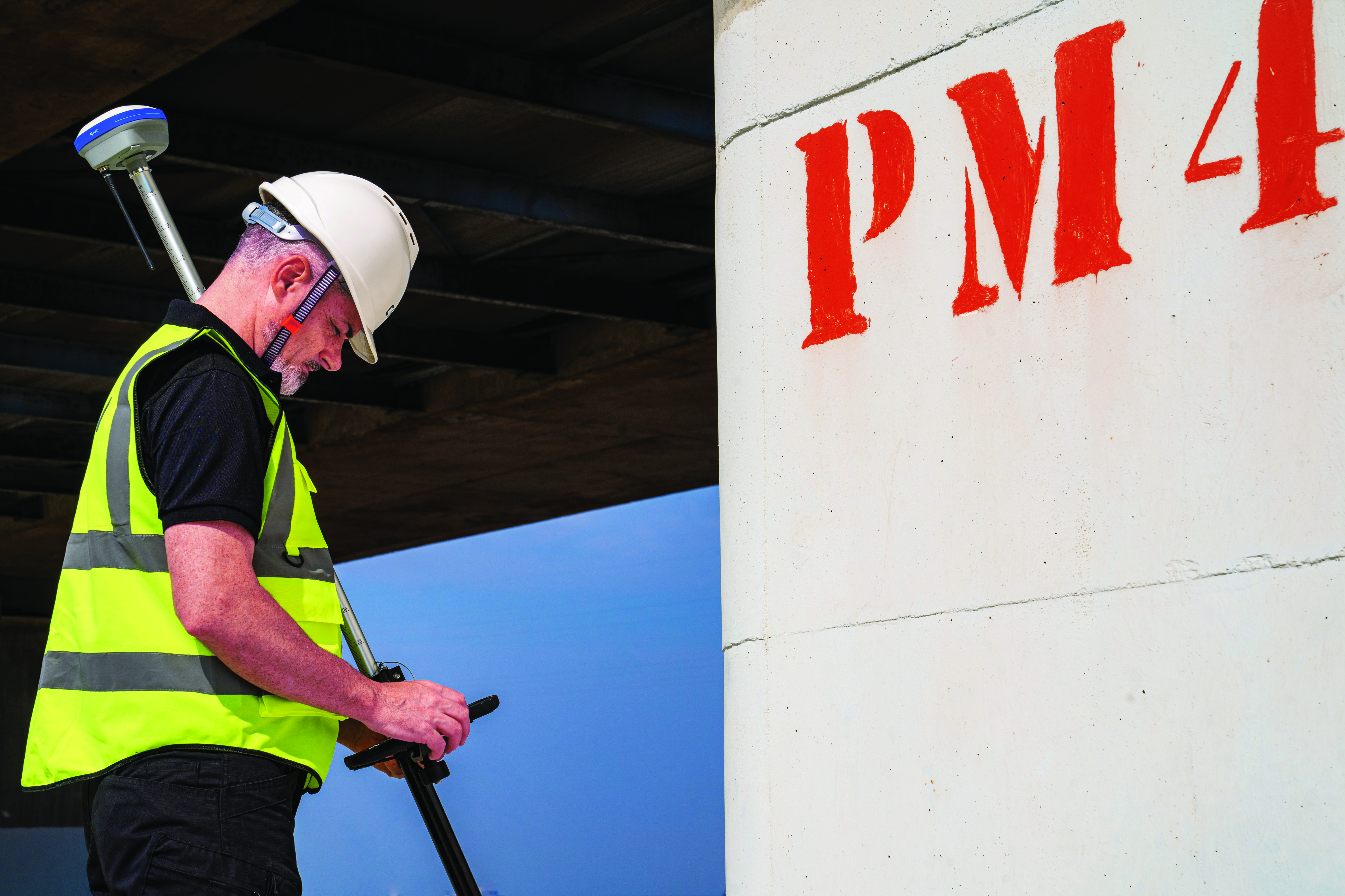
Common applications for tilt features include getting shots up against structures and improving sky view. For example, for this bridge column with sky partially obstructed by the bridge deck. (Image: CHCNAV)
Such magnetic oriented tilt compensation had been implemented on rovers several years prior to no-calibration methods, by manufacturers that included Javad, Trimble, Topcon, and others. The calibration step often involved rotating the rover vertically in eight or more horizontal positions. This was cumbersome, and the orientation quality changed over time, mostly unbeknownst to the user. It was no surprise that “mag tilt” never really caught on, and unfortunately it made some users wary of tilt in general, even when no-calibration solutions came along.
“The third step was the development of the second generation of tilt compensation, using hybrid positioning based on GNSS + IMU,” Wang said. “This technology was less affected by magnetic interference, but still required initialization of the IMU by shaking the survey pole.” I had tried several models from manufacturers of early “minimal calibration tilt” enabled rovers. For each, a certain amount of movement had to be induced on the pole, by walking around a bit, swinging the pole back and forth, or in a circular sweep. It often did not take more than a minute or so, and then normal moving around on the site would usually keep it calibrated. This was a tremendous step up compared to the old “mag tilt.”
“More recently, we are proud to announce the fourth step in our tilt measurement technology integrated into our new i93 GNSS RTK rover,” Wang said. “Our Auto-IMU technology further simplifies the IMU initialization process by observing acceleration at some point between startup and RTK operation. This replaces the previous repeated shaking of the survey pole for initialization. In fact, users can initialize the IMU while walking or moving normally. In addition, once initialized, the IMU feature is not easily lost even if the pole is carried on the shoulder, held horizontally, or even upside down.”
Wang said that all current CHC survey rovers are equipped with their newest tilt compensation technology. Since the international launch of their first CHCNAV GNSS RTK with IMU, the i90 GNSS in 2019, they have continued to incorporate this feature into all subsequent GNSS rovers. “Based on feedback from users, we know how valuable this feature is,” said Wang. “That is why we have made tilt compensation a standard feature on our current i73, i83, i90 and i93 models.”
Uptake
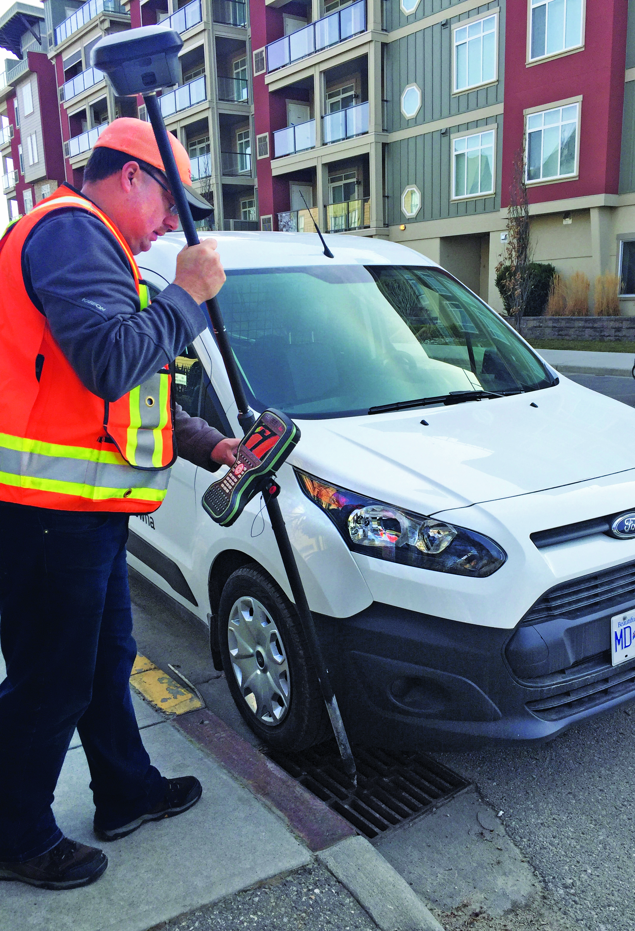
Greg Maier of the City of Kelowna, Canada, was an early adopter of tilt. He found it invaluable to access hard to reach features, such as this inlet under a car, and for safer surveying along the edges of roadways. (Image: Greg Maier)
For the past year, I’ve been talking to other GNSS manufacturers, their dealers, and customers, together with monitoring the subject in surveying and construction groups and forums online. Manufacturers have reported overwhelmingly positive feedback from dealers and customers about the tilt function. Typical feedback focuses on convenience and time savings of not having to level the pole manually.
“Based on our research, we have found this feature to be extremely useful for surveying and staking out on construction sites,” Wang said. “It has increased speed and efficiency by up to 30%.” I have heard similar statistics from each of the manufacturers contacted, as well as their dealers, and most of their customers that have used tilt.
There are common threads to much of the feedback from various sources: the tilt function is now an indispensable tool for many surveying applications.
As Wang noted, “While some users still prefer to use the traditional bubble to plumb the pole, we have seen a clear trend toward adoption of the tilt function in the field. The benefits of tilt, such as faster and easier surveying, are becoming more apparent to our users. As we continue to improve the accuracy of our tilt-compensation, we expect that more and more users will choose this convenient feature over other traditional GNSS rovers in the future.”
Another common observation (no pun intended): even if the pole-tilt feature offers significant convenience and time-saving benefits, it may not be the best option for tasks that require very high accuracy, such as surveying control points. For such tasks, manufacturers, dealers, and users recommend using the traditional bubble on a pole with a bi-pod mount for more accurate measurement.
As something completely new, the uptake across the surveying profession and for construction took time to grow. “It took quite a while to catch on here,” said Keith
Belsham, branch manager for Spatial Technologies, a measurement solutions dealer in the Vancouver region of British Columbia Canada. They specialize in solutions from Leica Geosystems and were an early provider of the Leica GS18 T, widely recognized as the first GNSS rover with no-calibration tilt.
“My perception is that in the United States and some other countries, there are more companies trying to stay at the top of technology,” Belsham said. “However, in our region surveyors are very cautious and need to do a lot of checks and look to see how others respond before they consider it. It was that way with other new technologies; I have memories of numerous total station demonstrations, when prism-less EDM’s were first coming out, where surveyors would pull out a tape measure to check whether the instrument was giving the correct distance.”
About three years after the introduction of no-calibration tilt is when Belsham said it really took off in his region, and it is now quite popular. He gave an example of a customer buying a Leica GS16 (no tilt), saying that they did not see a need for tilt, considering the extra expense. They then upgraded a week later once they were in the field and recognized many instances where the tilt would have saved them time.
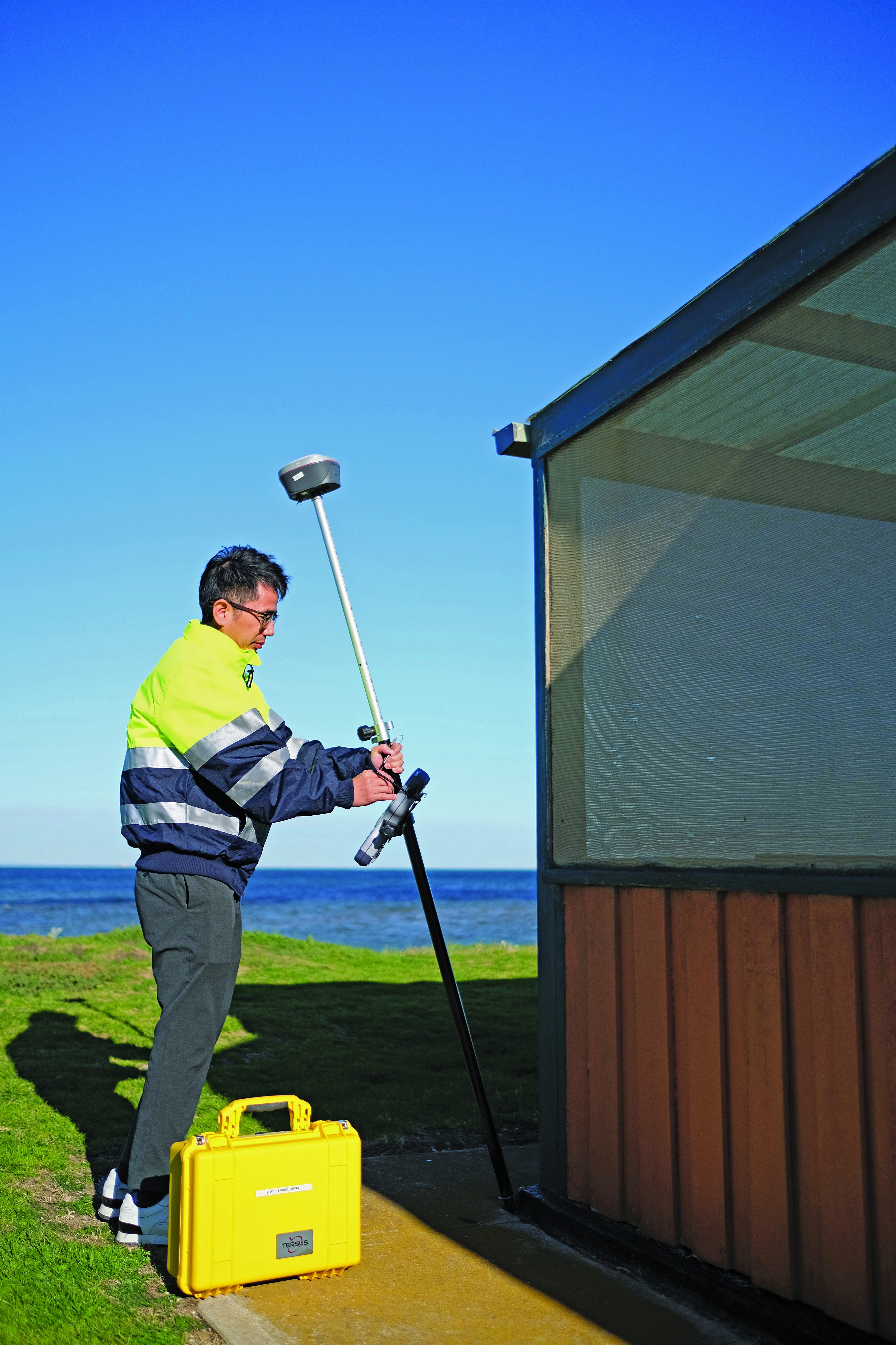
Rather than go the OEM route, Tersus GNSS developed its own GNSS board, positioning engines, and IMU tilt integration. (Image: Tersus GNSS)
A Spatial Technologies customer that has found tilt useful for numerous applications is Lucas Geomatics, a surveying firm based in Surrey B.C. “When I set up GNSS units for construction companies, tilt is great as they don’t have to be super accurate,” said Peter Smith. “I mean, here’s a machine with a bucket that’s 3 f wide, and the bucket is about an inch thick. The grade checked does not have to be super accurate for the machine to hit it, because end users in construction companies do not have to do precise surveying. They’re great guys who dig trenches and tilt gives them more than enough precision for their needs.”
Among the many uses Smith has found for tilt, he has also adapted it in a very creative way to deal with areas of deep foliage. A common approach to working in thick foliage is to raise the GNSS rover up on a tall or extended pole; this can increase the number of satellites viewed and reduce multipath. However, working with a bubble low enough on the pole to see makes it quite difficult to keep the rover at the top sufficiently still and plumbed over the tip. I remember some clever (albeit questionable) solutions folks cobbled together to help plumb very tall poles, such as a small live video camera pointing down over a bubble near the top of the pole to view on a phone. Smith said that tilt solved this problem, and he uses various tall rods, including one that extends to as much as 12 m. He chose a non-conducting pole, such as those used by utility companies for high foliage.
He does prefer to use the rover on a bipod, though, and bubble for control and points requiring very high precision. He sets the data collector software to log positions at 5 Hz or 10 Hz (standard in most systems) and has the software average multiple positions over the course of a minute or more.
Smith said that tilt has made a lot of difference in their surveys, especially where they want a lot of productivity, but do not need very high precision. Part of why he is impressed with the GS18 T is that they had upgraded from an older system, that only used two constellations, to full constellation support on their new rover.
Stability through motion
It sounds counter to one of the key principles for surveying measurement: the instrument and pole must be kept very still. However, in other data collection technologies, including aerial mapping and mobile mapping, leveraging predictable motion, acceleration, and trajectory caught on decades ago. There are numerous integrated GNSS + IMU solutions from, for instance, Applanix and NovAtel, that are the key positioning components for kinematic mapping systems. Such integrated sensor solutions are also in broad use now for UAV real-time and post-processing workflows.
One challenge for integration into survey rovers, was miniaturization. Additionally, such solutions needed a wealth of satellites and signals to be usable at tilted angles. The Galileo and BeiDou constellations reached full complement at about the same time as no-calibration tilt was introduced. Some manufacturers even integrated new antenna designs to better utilize satellites at tilted angles, for example in the Leica GS18 T.
The electronic bubble aspect of such solutions was in some ways the easiest to achieve. Depending on the quality of components, multiple tilt sensors can measure the angle of tilt at precisions matching, or even bettering that of typical pole bubbles. Plus, they are built into the rover boards with a direct relationship to the axis and phase center, whereas the bubble is external, down on the pole.
Integrated IMUs, with as many as nine axes, are highly sensitive, as are accelerometers (if an integration utilizes those). Skeptics always point out that IMUs are subject to drifting over time. However, the observed high-rate GNSS positions and motion sensors are continuously updating the calibration of the IMU. It is true of no-calibration tilt systems that if you hold the pole still too long, it will lose its calibration. Or if you move it too fast. Though on every tilt rover I’ve tried, I moved it around vigorously and spun it (more than would happen in normal operations) and it still kept its calibration. There can also be instances of environments with excessive multipath hazards — such as heavily wooded areas, urban canyons, or congested construction sites — where users often find it best to turn off the tilt for certain shots.
Industry penetration
Tilt for shooting inverts. (Image: Lee Landman)
While manufacturers have approached the GNSS/IMU solution in varied ways, the fundamentals are the same. Once some of the major vendors developed and integrated tilt, they began offering this feature for OEM customers, and in recent years we see tilt on many other brands worldwide. There are relatively new players in the market that took a different approach, developing not only their own GNSS boards and positioning engines, but IMU solutions as well.
Tersus GNSS has rapidly gained a presence in various global markets, though relatively new in North America. While starting as an OEM, the company pivoted to developing its own boards in 2015, and GNSS + IMU integrations more recently. It recently published a paper about what they call its “Extreme RTK Solution” that has a section with data from their own tests for both plumbed and tilted observations.
I did some quick tests with a Tersus Oscar Ultimate, at various angles of tilt, and in mixed environments. The results aligned closely with those in the paper, as did tests with other tilt rovers. I have had the opportunity to try rovers of several different brands, to check precision at various tilt angles against points established with static observations (to see how much the tilt added to the total error). While these were not comprehensive tests, I did compare notes with surveyors who did their own tests, and we’ve all been finding out the practical limits of tilt. Perhaps part of why tilt took a while to catch on was that surveyors needed some time with these units in real-world environments, to get a feel for sweet spots for tilt for different tasks that have specified error budgets.
To get an idea of potential productivity gains, I did a small topographic survey of an area I had previously surveyed with a conventional rover, total station, and scanner. The total station and tilt-less GNSS took about the same amount of time — but with tilt it took about half the time. Many variables can and do come into play, but the figure I keep hearing of up to 30% efficiency gain for many applications seems realistic. Certainly, for asset and resource mapping, tilt could easily fit the looser precision requirements.
As for degradation at various angles of tilt, checks against static points (beyond standard GNSS error) showed negligible differences under 5°, 1 cm up to 15°, 2 cm or more around 45°, and 3 cm or more at 60°. This was just a cursory look, and indeed any surveyors that use tilt should do their own testing. I did notice in the data that when doing simple topo shots, just moving around the site, the pole did not often exceed 5°. Therefore, moving around quickly and efficiently for topo, not having to look at the bubble, improves productivity without significantly compromising quality.
Layout, as surveyors and construction folks who use tilt say, can be quite a snap compared to the old “plumb-shoot, move-plumb-shoot, move-again-plumb-shoot, etc.,” process. You simply move the tip of the pole around until you are on the point.
Enabling further sensor integration
Tilt compensation has now extended to non-GNSS tech, for instance Leica Geosystems AP20 prism poles (used with robotic total stations). (Image: Gavin Schrock)
No-calibration tilt, and multi-constellation GNSS, have enabled further developments that may not have been practical otherwise. Leica has since added an image point extraction feature to its GS18I. This marries the tilt and a camera with a clear path to processing the images in the data collector software. With tilt running, and at ranges under 6 meters, you can roughly aim the camera side of the rover toward say, features under an overhang, that you would not otherwise be able to shoot with a GNSS alone. You walk past the features as the camera takes a series of images. Then, in the software, you identify the points in multiple images and photogrammetrically it gives the offset. You can also process the image series into point clouds. There were several attempts at this sort of solution in the past by various brands. However, without tilt it was too cumbersome as you would need to stop and plum for each image in the series. As one user told me, the new image point features are “like having a UAV on a pole.”
Tersus GNSS has taken a slightly different approach to their image point solution. You pick the point you desire in the camera view on the data collector, and then move along as the software automatically identifies the same point in subsequent frames, until it has enough matches from multiple angles to calculate the offset. CHC Navigation has just announced its own image point feature, with a two-camera integration in the i93 Visual GNSS RTK rover.
Pole tilt also has been integrated into non-GNSS solutions. For instance, the recent release of a prism-pole tilt solution by Leica, the AP20. A constant stream of positions of the prism, from the total station, takes the place of GNSS in this application. They’ve also included a rather clever automated pole-height feature.
What could be next? Perhaps small solid state lidars on rovers, or combined lidar/camera solutions such as on an iPhone/iPad, or a tiny SLAM scanner (that could also aid in position stabilization)? Not to mention what might be coming in the not-too-distant future in the realm of quantum sensing.
In considering all feedback about no-calibration tilt, it seems it is very much here and here to stay. There are many who love it and try to use it for everything (perhaps, in some cases, too many tasks). For others, it is conditional love: use where appropriate. While others still hate it immediately, perhaps on principle, though I find those folks typically have never tried it. Legacy tools and methods provide comfort and known levels of risk. New features such as tilt, provided some time is spent gauging its performance and appropriateness for various tasks, can deliver productivity gains that should prompt reevaluation of some long-held assumptions.
NV5 Geospatial has mapped more than 26 million acres of North America’s shoreline and riverine environments across more than 200 projects.
The projects have spanned from the Nuyakuk River in Alaska, Lake Tahoe in California, the Rio Grande in Texas, the entire coasts of South and North Carolina, the Achigan River in Quebec, Chesapeake Bay in Maryland and the Florida Keys.
In 2022, the company mapped and acquired topobathymetric lidar data for 14 projects including the Yellowstone River, Wyoming; Hells Canyon, Indiana; Revillagigedo Island, Alaska and Iles de la Madeleine in Quebec.
NV5 Geospatial first mapped these environments in 2012 using high-resolution bathymetric lidar and natural color imagery. The company mapped 34,051 acres of shoreline along the Sandy River, located in northwestern Oregon, to study the ever-changing basin geomorphology.
NV5 has also signed a two-year contract with the National Geodetic Survey of the National Oceanic and Atmospheric Administration to provide topobathymetric lidar, 4-band imagery and mapping of 3,115 sq miles of the Maine shoreline.
“For a decade we have been helping local, state, and federal government agencies as well as commercial and private entities gain the insights they need to solve some of their most challenging nearshore and riverine projects through our mapping technologies including topobathymetric lidar,” Kurt Allen, vice president of NV5 Geospatial, said. “Whether it be mapping the shoreline after a hurricane, updating the national shoreline, assisting water boards with flood planning, or hundreds of other possible use cases, we are constantly improving our technology and scalability to always be at the ready for our customers.”