Tag: digital edition

  • Eos Positioning Systems: Building a System to Build an Island Resort

    Eos Positioning Systems: Building a System to Build an Island Resort

    When Chris Kahn arrives by helicopter on the island of Barbuda, in the Caribbean, he sees reef-lined beaches, meadows, marshes, and construction underway on a private club consisting of more than 200 luxury family homes, a world-class golf course, and other amenities. Construction on the project, by Discovery Land Management, will last at least another 10 years, said Kahn, who began working on it in late 2019. The island, which can also be reached by ferry or small plane, is 15 miles long and has a local population of about 1,500 people.

    The biggest challenge for the project was the total lack of internet connectivity on the island, except for satellite communication at basecamp. A consultant who designed the golf course irrigation layout had attended many meetings for the project in which the participants discussed in vain how to coordinate their work without an internet connection, a problem that a few engineering firms had also been unable to solve. So, he suggested that they turn to Kahn, with whom he had already worked closely. Discovery Land Management hired Kahn, founder and owner of AlphaRTK, to provide a common operating picture for the teams of surveyors, architects, planners, construction workers and landscapers building the resort and the golf course.

    Chris Kahn installing a UHF base station (its antenna is visible in the foreground on a telescopic mast) atop a 50-ft water tower. (Photo: Chris Kahn, AlphaRTK)
    Chris Kahn installing a UHF base station (its antenna is visible in the foreground on a telescopic mast) atop a 50-ft water tower. (Photo: Chris Kahn, AlphaRTK)

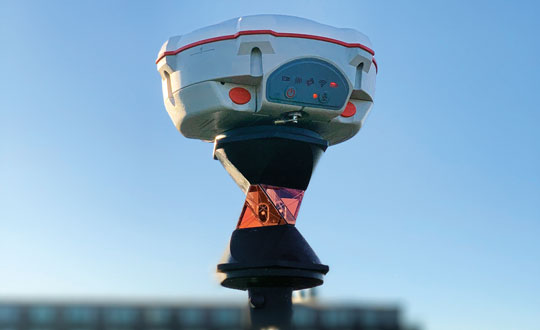
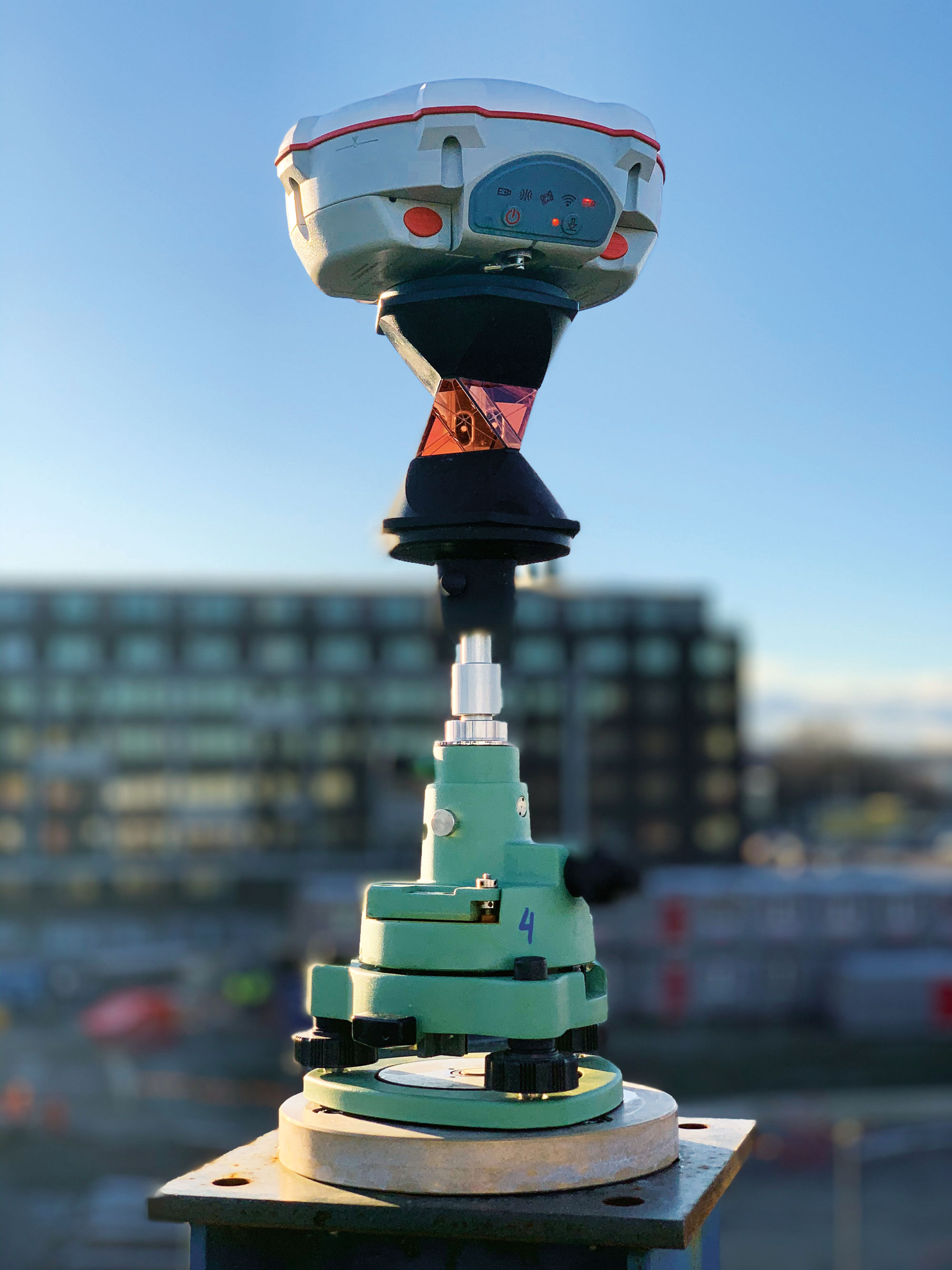
    RTK UHF Base Station

    Kahn proposed they build their own RTK UHF base station. “You can get about a seven-mile line of sight out of UHF and with repeater radios we can extend that, which is what we eventually did,” Kahn explained. So, he put the base station where the project had an internet connection and relayed the UHF signal from there. He gave the teams Eos Arrow Gold GNSS receivers, which have a UHF plug on the side, with Satel UHF radios. “It works like a charm,” he said. He also set up for the project an ESRI ArcGIS Online account, which now hosts all its maps and data.

    “They’re doing a lot of earthwork that needs survey-grade accuracy but does not legally require a survey,” Kahn pointed out. Starting in about 2010, he explained, RTK accuracy began to explode for geographic information systems (GIS) and unmanned aerial systems (UAS). “It’s accelerating,” he said. This has greatly increased opportunities for high accuracy data collection beyond traditional surveying tasks such as boundary surveying. “My niche, and one of the places where there’s a lot of pain, is this interoperability between projects that have surveyors and landscape architects and all sorts of folks in subject matter expertise that are trying to come together to build something.”

    Like the rovers, the base station contains an Eos Arrow Gold, with a 35-watt Satel UHF output. Project staff and contractors can connect to it with any device that can accept that UHF protocol. Their rovers are set up to work with ESRI ArcGIS Field Maps, so that workflow is very smooth, Kahn said. The project started where they began to build the golf course, at a worksite seven miles away from the base station, across open water. Kahn then installed a UHF repeater antenna there and additional ones as construction moved inland.

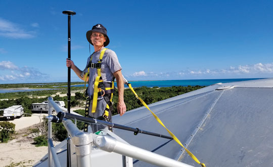
    The island is relatively flat, but the sand dunes are quite large. Therefore, to enable the line of sight that UHF requires, Kahn had to install the antennas for the repeaters as high as possible. For one, he used a whip antenna on top of a 15-foot telescopic mast on top of a 20-ft high deck. A repeater antenna costs about $2,500 and takes a few hours to install. “It is fairly old technology,” he said. “I tend to look for an easy button and string together inexpensive ways to do things fairly rapidly.”

    UAS Photogrammetry

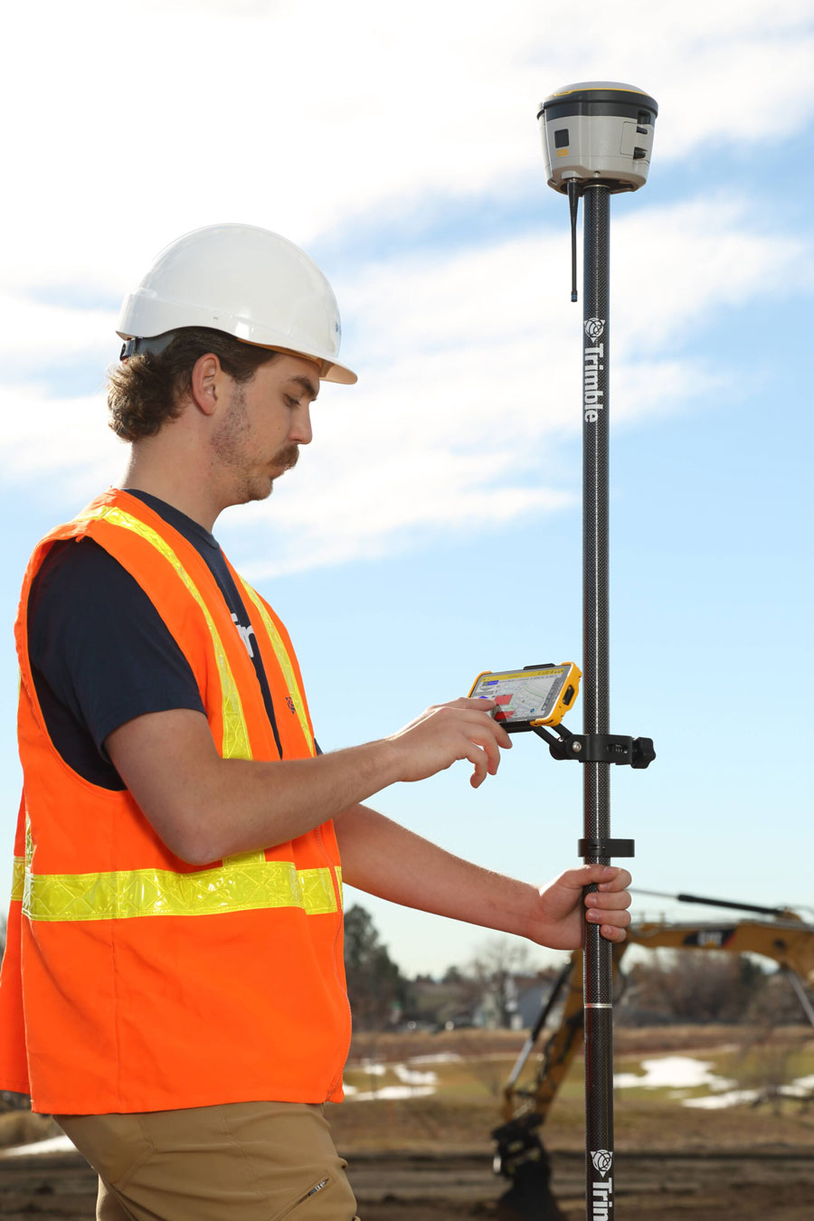
    The project covers 2,500 acres at two locations. While traditional surveyors are working on the project for building construction, their speed is too slow for the crews doing earthwork, particularly on the golf course. This involves pushing sand around, dredging lagoons, and building the course, which requires taking many elevations very rapidly. To speed things up, Kahn decided to use UAS to fly frequent photogrammetry collections. He began by installing ground control points, surveyed them, and put them around the construction sites. He then trained the laborers on the project to conduct high-accuracy, survey-grade workflows using UAS the flight paths of which he programmed.

    All the laborers need to do is launch the UAS and, after each flight, extract the SD memory card and upload the data to a shared directory. “They don’t even have to put the props on anymore because they just fold out,” Kahn said. He processes the data and publishes the aerial photogrammetry into the project maps. The next day, everyone on the project has access to survey-grade accurate aerial imagery and a map.

    “How frequently they fly them depends on how much activity is going on at the various sites,” Kahn said. “That turnaround time can be as short as a few hours if they need it, between them flying it, uploading it for me, and having it back in their maps. Everything has sub-inch positional accuracy. When they zoom into some of the foundation pilings on the homes, they’re aligning perfectly.”

    Survey-Accurate GIS

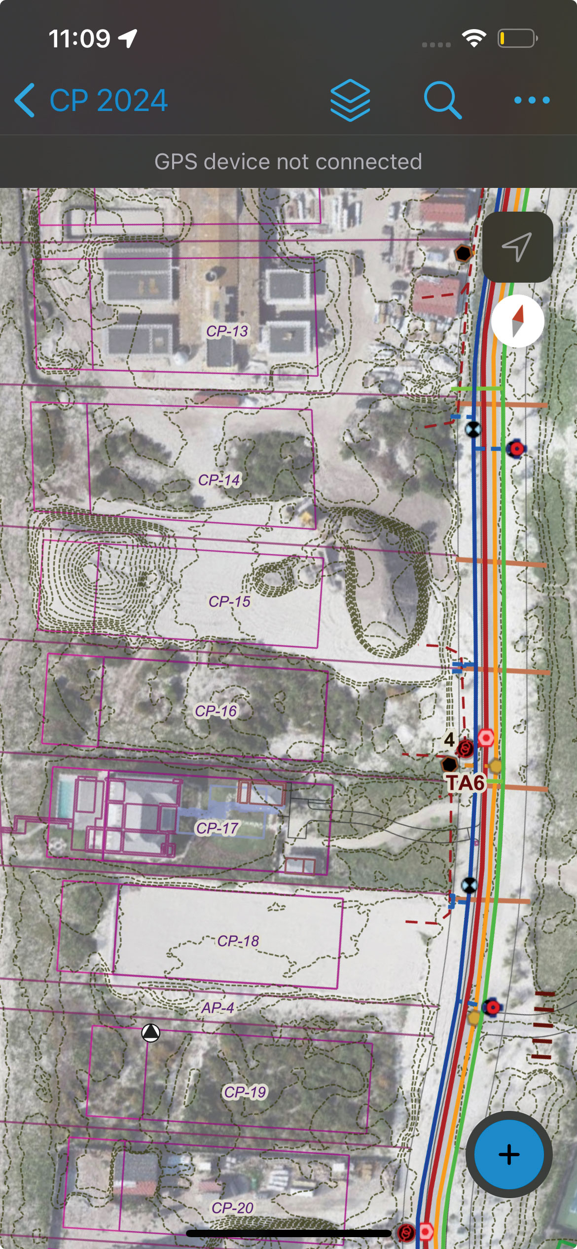
    Project managers need GIS to see everything — survey, landscape design, architectural design, engineering design — in a common operational picture, which they were not able to do prior to Kahn joining the project. “I was looking at email threads that were 45 messages long, with two dozen people on three different continents, talking about where something’s located and referencing something else, with many civil drawings attached as PDFs — one from the landscape architect, one from survey, one from a civil engineer. They were saying, ‘Well, this doesn’t look like it matches.’ I was brought in to make it all one pane of glass.” That requires overlaying survey-grade accurate architectural and engineering information on the GIS information.

    “That’s where you run into this niche area in which I work that often surveyors don’t fully understand,” said Kahn. “In the United States, there are civil engineering surveyors and design-build shops that include geospatial, though it is not commonplace. Outside of the United States, it is rare.”

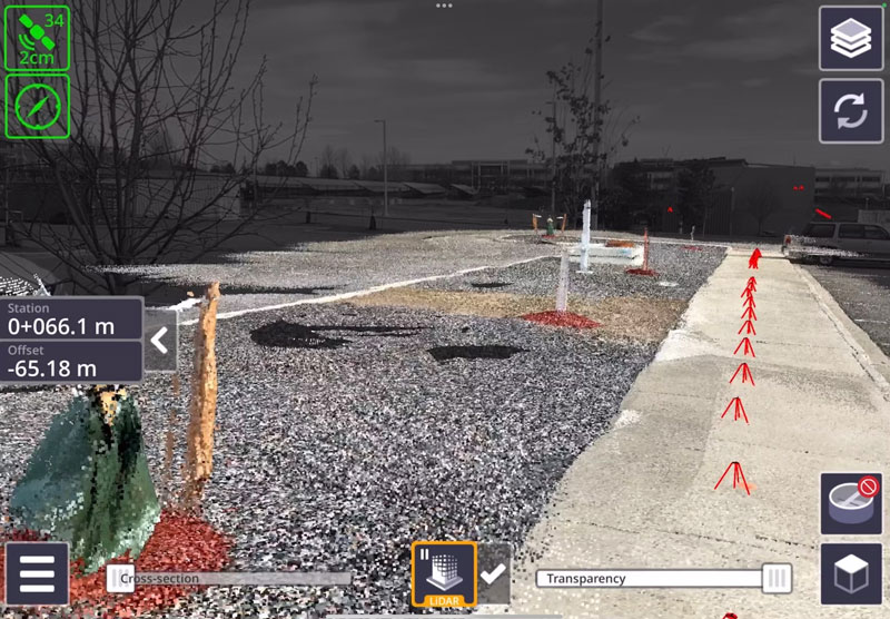
    The rovers for GIS data collection are sub-centimeter accurate, as are the ground control point targets that Kahn installed for the UAS workflows. Workflows were designed for simplicity, allowing laborers to reliably perform UAS and GNSS data collection.

    ESRI ArcGIS Field Maps is well suited for this project because it works offline. As they walk around the site and try to understand what they will build, planners, architects and engineers can see the most current maps on their phones, rather than having to consult PDFs or paper.

    “I had to do a lot of work with their engineering firm, though, to get their 3D civil drawings to interact with GIS,” Kahn recalled. “Now, all the line work coming from engineering is perfectly aligned, and all field adjustments made by construction are real-time updated in the design drawings. You can see how accurate this GIS is. Everything is perfectly placed, and these are data coming from four different places: GIS, UAS, engineering design, and survey. Everything is aligned within one to two centimeters.”

    iphone screenshot, showing lots, foundations, finished construction, virgin sand, and utility lines. (Photo: Chris Kahn, AlphaRTK)
    iPhone screenshot, showing lots, foundations, finished construction, virgin sand, and utility lines. (Photo: Chris Kahn, AlphaRTK)

    With golf course building, “design is a suggestion,” Kahn said, and many changes are made in the field. “In fact, the pace of ‘field adjustments’ was a crucial reason I was brought in. Engineers cannot wait a year for an as-built drawing set to be delivered.”

    Cut-and-Fill

    This workflow streamlines the many cut-and-fill operations involved in the project. “Coco Point is a good example,” Kahn said, “because some of the lots there are completed.” Zooming into one of the completed lots, he can see the nine-foot grade for which one construction company is responsible and the 11-foot grade for which another construction company is responsible. “It’s important for them to know those two grades because of cost; it’s very expensive to bring fill in here. So, as they’re doing these drone flights, they have dashboards that show them how much fill they need to bring in.”

    The common operational picture enables project managers to optimize the cut-and-fill transfers. The golf course was particularly challenging because it is in a very swampy area, making it difficult to move the dredging equipment. So, they asked Kahn to design the path for the trucks and determine how much fill they would extract out of these lagoons. “I knew they needed this much to meet design on the green and could get this much out of the lagoon,” he said. “It was very helpful for them procedurally with the planning.”

    Challenging Environment

    The environment on the island is challenging. “It was wild,” Kahn recalled. “Nothing but wild donkeys and enormous boars, which I really learned to avoid after a while. It is mostly wetlands, so it is hard to get around.” A construction manager told him: “Chris, I’ve led projects on every continent, but this place is the [expletive] moon.”

    The challenging environment and the lack of internet connectivity make the system that Kahn set up particularly helpful, because it provides accurate data quickly and with a streamlined workflow. “The big story here is that common operational picture,” Kahn said. “It’s taking the best tools of the GIS/geospatial world — such as RTK and UAS. They must be accurate, work offline, and be very easy and fast. You must maintain that accuracy so that the surveyors who work on this project aren’t going to yell and scream.”

    The project also requires building and maintaining utilities — water, gas, sewer, stormwater, electric, and telecom — which are all in underground plastic pipes and are often not placed as designed. “Doing the digital ‘as building’ up front, as it goes in the ground,” Kahn said, “saves time and money down the road.” Additionally, the turnover of people who work on these projects, including managers, is high, so institutional knowledge is constantly lost. “Utilities in the United States have a fairly stable workforce, but in the resort world, everything’s plastic and sand,” said Kahn. “The high turnover and the low institutional knowledge make it even more important to have a true digital twin.”

  • Seen & Heard: Deep sea coral reefs and lava in Iceland

    Seen & Heard: Deep sea coral reefs and lava in Iceland

    “Seen & Heard” is a monthly feature of GPS World magazine, traveling the world to capture interesting and unusual news stories involving the GNSS/PNT industry.


    Photo: NOAA Ocean Exploration
    Photo: NOAA Ocean Exploration

    Exploring the Largest Deep-Sea Coral Reef

    Scientists have mapped the largest deep-sea coral reef, stretching hundreds of miles off the U.S. Atlantic Coast. While researchers have known since the 1960s that some corals were present off the Atlantic Coast, the reef’s size remained a mystery until new underwater mapping technology made it possible to construct 3D images of the ocean floor. The National Oceanic and Atmospheric Administration (NOAA) and a team of scientists recently published maps of the reef in the journal Geomatics. The reef extends for about 310 miles from Florida to South Carolina. The total area is nearly three times the size of Yellowstone National Park.

    Photo: ESA
    Photo: ESA

    Lava in Iceland

    Grindavík, a tiny town in Iceland, stands on the brink of volcanic lava flow in images captured by the European Space Agency (ESA). The lava originates beneath the Svartsengi volcano system — roughly 2.5 miles north of the town — which erupted on December 18 and January 14. ESA’s Sentinel2 satellite revealed the glow of the lava flow’s heat, not far from houses and other infrastructure within Grindavík. The town, with just 3,800 residents, has faced constant evacuations, as well as mini-earthquakes as a result, The Guardian reported.

    Photo: Maris Maskalans / iStock / Getty Images Plus / Getty Images
    Photo: Maris Maskalans / iStock / Getty Images Plus / Getty Images

    Lidar Reveals Lost Cities in the Amazon

    In the Amazon rainforest, archeologists have discovered a vast and highly complex system of ancient cities dating back nearly 3,000 years. Located in Ecuador’s Upano Valley, the structures lie in the eastern foothills of the Andes mountains, according to a study published in the journal Science. After more than 20 years of research, the ancient urban centers were only discovered when the Ecuadorean government employed lidar technology. Researchers from France, Germany, Ecuador and Puerto Rico conducted a lidar survey that covered roughly 300 km2, which revealed a landscape full of organized human activities, including more than 6,000 rectangular earthen platforms, as well as agricultural terraces and drainage systems. According to the study, these structures formed at least 15 distinct settlements, which were connected by a system of wide, straight roads.

    Photo: nickalbi / iStock / Getty Images Plus / Getty Images
    Photo: nickalbi / iStock / Getty Images Plus / Getty Images

    Tracking Cattle from Space

    Australian scientists are attempting to track 1,000 cattle and buffalo using artificial intelligence (AI), and GPS satellites, reported euronews.next. An estimated 22,000 cattle and buffalo roam free in a remote area of Arnhem Land, Australia, though the exact number is unknown. Scientists are now collaborating with stockmen and indigenous rangers in a four-year program that involves monitoring feral animals from space. Titled SpaceCows, the remote herd management system is backed by the Australian government’s Smart Farming Partnership initiative. Local rangers and stockmen are chasing and catching animals to attach solar-powered tags with GPS receivers.

  • CHCNAV: Expanding a Highway in China

    CHCNAV: Expanding a Highway in China

    Due to China’s rapid growth, the G85 highway, which opened in 1995 and connects Chongqing to neighboring provinces, in 2023 required expansion to four lanes. Like with any construction project, the first step was a survey. When the highway was built, surveyors had to rely on total stations and other optical instruments. Today, despite the availability of GNSS receivers, surveying over long distances in rugged terrain is still challenging.

    Orthophoto of the service area in the section of the G85 highway that is being enlarged. (Photo: CHCNAV)
    Orthophoto of the service area in the section of the G85 highway that is being enlarged. (Photo: CHCNAV)

    Li, a surveyor responsible for surveying a 5 km section that included a service area, bridges, culverts, and embankments, wanted to avoid closing lanes, which would have been expensive and dangerous due to heavy traffic. Additionally, using only GNSS receivers and total stations to complete the project would take a long time and potentially require multiple surveys. Instead, he opted to conduct a lidar survey.

    To meet the project’s 2 cm root mean squared error (RMSE) accuracy requirement, Li established ground control points (GCPs) before scanning. To avoid disturbing the traffic and ensure safety, he placed the GCP targets within 50 m of the roadside. Then, a 50-minute flight was enough to scan the 5 km section.

    The data was then imported into CHCNAV’s CoPre lidar processing software, which performed point cloud correction and bundle adjustment, increasing the absolute accuracy of the road surface point cloud to the required 2 cm. Next, the software performed point cloud classification, modeling, point cloud coloring, and image georeferencing and generated depth maps.

    The resulting color point cloud clearly shows road markings and other features, and makes it possible to accurately measure the locations of drainage ditches, slopes, and culverts. For power lines crossing the highway, the point cloud provides accurate measurements of the minimum distance between the lines and the road for safe equipment operation.

    Lidar scanning captures detailed ground surfaces, but road design relies on actual terrain conditions. Using CHCNAV’s CoProcess post-processing software — which has built-in adaptive ground point filtering algorithms — the team removed vegetation, guardrails, and vehicle returns, revealing the bare ground for design. They also accurately extracted road features, including dashed and solid lane lines with width and line type parameters, to enhance the efficiency of subsequent design efforts.

    Lidar point clouds provide much richer ground detail than traditional surveys. This allows CoProcess software to automatically generate cross-sections from processed point clouds, while manual editing options are available for special terrain, such as roadside ditches. Sections can be exported to design formats or CAD drawings for immediate use.

    For this project, two engineers performed the field scanning, and one engineer handled the point cloud processing, classification, and modeling to provide multi-dimensional data that met the 2 cm accuracy criteria.

  • ComNav Technology: Building Sweden’s Tallest Tower

    ComNav Technology: Building Sweden’s Tallest Tower

    When completed, the Karlatornet will be Sweden’s tallest building and redefine the skyline of the city of Gothenburg, rising to 74 stories and 246 meters (the Burj Khalifa in Dubai, currently the tallest human-made structure, is 828 meters high). Ensuring that the building remains stable even when deformed by very strong winds, sun exposure, seismic activity, settling or shrinkage will require very high precision construction methods. To ensure its vertical alignment, the engineers are using the core wall control survey (CWCS) method, which relies on active GNSS control points, and SinoGNSS T300S high accuracy GNSS receivers.

    A SinoGNSS multi-constellation T300 GNSS receiver and a 360° prism mounted at the top of a building under construction. (Photo: ComNav Technology)
    A SinoGNSS multi-constellation T300 GNSS receiver and a 360° prism mounted at the top of a building under construction. (Photo: ComNav Technology)

    The CWCS method was first used during the construction of the Burj Khalifa and was subsequently applied in the construction of many other high-rise buildings around the world. Swedish surveying company Teodoliten decided to apply this method for the Karlatornet project. Core walls, which are key structural components of high-rises, require a layered construction approach, with multiple concrete pours for each core wall element. CWCS makes it possible to precisely align these core walls with the vertical axis of the building during construction, using GNSS receivers, total stations, inclinometers, and other tools.

    When constructing a tall building, it is essential to continuously measure the positions of various elements at its summit to ensure their vertical alignment. This is typically done by placing at the top of the building four GNSS receivers — referred to in this context as active GNSS control points — each with a 360° prism at the bottom. By sighting the prisms and using the 3D coordinates from the GNSS receivers, a surveyor then sets up a total station. This obviates the need for an extensive array of ground control points, which are often not visible from the top, and for holes in the slabs to accommodate vertical laser plummets. Additionally, observations from a nearby reference station are used to post-process the data from the GNSS receivers in post-processed kinematic (PPK) mode to achieve an accuracy of a few millimeters. The Karlatornet project uses four SinoGNSS multi-constellation T300 GNSS receivers for the active control points.

    It is also necessary to correct for the movement of the survey platform as the building’s main axis is flexed by the loads applied to it during construction. This is achieved by placing a series of high-precision dual-axis inclinometers along the core walls and then applying a least squares adjustment that takes into consideration the floor height of the measuring devices.

    The SinoGNSS T300 receivers operating in GNSS-RTK mode also will be used to monitor and document post-construction building deformations.

  • Trimble launches three new products

    Trimble launches three new products

    Trimble has released three new surveying and mapping products: SiteVision 5.0, TDC6 and Trimble Radio. All three products are available through Trimble Geospatial authorized distributors.

    Trimble SiteVision Software 5.0. (Image: Trimble)
    SiteVision Software 5.0. (Image: Trimble)

    SiteVision Software 5.0 is a high-accuracy outdoor augmented reality system, now with a 3D scan tool. The new 3D scan tool allows users to use lidar sensors available on some Apple Pro devices. The Trimble DA2 GNSS receiver is designed to capture point clouds efficiently and accurately with a single handheld solution.

    Users can visualize 3D scan data directly in the field with SiteVision’s augmented reality view. The software allows users to create as-builts of the job site on the go, measure and plan resource allocation, reduce scan times, supplement UAV data and more by combining scanning and precision in a mobile solution. The product aims to facilitate practical and accessible field-to-office workflows for surveyors, contractors and engineers.

    TDC6. (Image: Trimble)
    TDC6. (Image: Trimble)

    TDC6 is a handheld GNSS data collector designed for high-performance construction surveying.

    The device allows contractors to work with more complex data sets more effectively in the field, connect to the office for on-the-spot approvals, and quickly communicate changes to field crews.

    The small, rugged device offers integrated Wi-Fi and Bluetooth, built-in cameras and 5G compatibility in a lightweight, shock-, dust- and water-resistant package. The device integrates seamlessly with Trimble data collection applications, including Trimble TerraFlex GIS software and Trimble Access survey field software, as well as third-party apps such as Esri ArcGIS Field Maps.

    TDL450B radio. (Image: Trimble)
    TDL450B radio. (Image: Trimble)

    The TDL450B radio is a 450 MHz external radio with Bluetooth for transmitting, receiving and repeating GNSS corrections. It offers flexible configuration options and rugged reliability for efficient use of GNSS in various applications. Designed to support Trimble and third-party RTK base stations, this sophisticated radio modem puts Trimble’s newest data link technology in the hands of users on the job site. The TDL450B radio is an advanced, high-speed, wireless UGH data radio built to endure harsh conditions.


  • Russia’s space-based nuclear weapon? Here’s an educated guess

    Russia’s space-based nuclear weapon? Here’s an educated guess

    Earlier this week House Intelligence Committee Chair Mike Turner sounded an alarm about a serious national security threat. It had to do with Russia, a weapon, space, and something nuclear.

    For many, these clues conjured up images of bombs falling to Earth from space, satellites destroyed by powerful electromagnetic pulses, shrapnel impacting the space station, and so on.

    Yet, putting nuclear weapons in space would be a clear violation of the 1967 Outer Space Treaty to which Russia and the United States are both signatories. It would also significantly increase East-West tensions at a time when Russia has enough tension and international condemnation to handle.

    Thursday evening the White House calmed the waters a bit by saying that Russia was pursing an anti-satellite weapon that cannot cause physical destruction on Earth.

    The most reasonable conclusion to draw from all of this is that Russia is closing in on its goal of having a nuclear-powered electronic warfare capability in space.

    Such a reusable weapon could be far more useful than any one-use nuclear explosive device.

    Threat = Intent + Capability

    A lengthy and detailed 2019 article on the site “Space Review” examined indications that Russia had begun construction of such a device. Titled “Ekipazh: Russia’s top-secret nuclear-powered satellite” it begins:

    “There is strong evidence from publicly available sources that a Russian company called KB Arsenal is working on a new type of military satellite equipped with a nuclear power source. Called Ekipazh, its mission may well be to perform electronic warfare [EW] from space.”

    The author, Bart Hendrickx, goes on to explain that development of such a weapon would be entirely in keeping with reported Russian government plans. Citing one Russian language source he says:

    “… the deployment of EW platforms in orbit would be in accordance with a policy for Russia’s electronic warfare program until 2020 approved by the Russian government in January 2012. A summary of this policy indeed mentions space-based electronic warfare as one of the objectives to be accomplished in the period before 2025. More specifically, it talks about the need to deploy ‘multifunctional space-based EW complexes for reconnaissance and suppression of radio-electronic systems used by radar, navigation and communications systems.’”

    When intelligence agencies assess the severity of a particular threat, they look at an adversary’s desire or intent to carry out a particular act, and their capability to do so. If the reporting is correct, Russia has intended to put a nuclear-powered EW satellite or spacecraft in orbit for some time. This week’s political dust up may mean that the decades of hard work described by Hendrickx in Space Review have paid off and given them the ability to do so.

    More Useful Than Orbiting Bombs

    The United States is far more dependent upon space than any other nation. As regular GPS World readers know, this is especially true for the essential positioning, navigation, and timing services that underpin virtually every technology.

    Destroying satellites would quickly lead to a shooting war that no one would want.

    On the other hand, electronic warfare doesn’t necessarily lead to casualties right away and is harder to recognize as actual warfare. For example, Russia has been attacking NATO countries, ships, and aircraft in the Baltic with GPS jamming and spoofing on and off since mid-December. No one has died (yet) and NATO, to the best of our knowledge, has not responded.

    Rather than destroying satellites, how much more useful is it to be able to temporarily disrupt the operation of one or more satellites? Or perhaps one type of satellite, such as GPS?

    Such attacks are reversable, so the attacked party is less likely to send bombs and bullets in return right away. And if the attacker gets what they want, or suddenly discovers they have gone a bit too far and are approaching a kinetic exchange, backing off is as easy as flipping a switch.

    Just the threat of being able to deny GPS or other satellite signals over a wide area would be useful.

    In fact, Russia has already made this kind of threat and it didn’t backfire.

    In November 2021, prior to its invasion of Ukraine, Russia used a ground-based missile to destroy one of its own defunct satellites. Shortly thereafter Russian state-sponsored media claimed the demonstration “… means that if NATO crosses our red line, it risks losing all 32 of its GPS satellites at once.” Aside from a strong diplomatic tongue-lashing, there were few consequences. Additionally, wherever the “red line” was, it seems that NATO did not cross it.

    Nuclear Powered EW Most Likely

    It’s hard to know what more will be revealed, if anything, about this week’s dust-up over Russia, weapons, space, and nuclear.

    But Russia has long prided itself on its electronic warfare prowess. It sees EW as a counterbalance to the West’s dominance in high tech weapons and warfare.

    It is highly likely that Russia is executing its plans to extend this prowess and advantage into space with a nuclear-powered EW satellite.

    Whether or not this is the root Washington’s kerfuffle, the possibility should be an on-going concern for the United States.

    Our dependance on space makes us vulnerable. Our critical over-dependence on space for PNT, especially in light of the terrestrial PNT alternatives available to Russia and China, exposes our jugular and virtually invites attack.

    We have placed most of our eggs in the same basket — and there are too many ways in which it can be knocked to the ground.

    Until the United States establishes a resilient national PNT architecture, one with GPS at its center supported by other diverse and robust sources, we will continue to unintentionally encourage such things as space-based nuclear-powered electronic warfare and be at severe risk.

  • Tracking planes but not trains

    Tracking planes but not trains

    Matteo Luccio
    Matteo Luccio

    Every day, the Federal Aviation Administration (FAA) monitors and assists more than 45,000 flights — up to 5,000 at any one time — across the more than 29 million square miles that make up the U.S. National Airspace System (NAS). It knows the position of each plane with an accuracy well within its length.

    Three key NAS systems are the Automatic Dependent Surveillance-Broadcast (ADS-B), the Airport Surveillance Radar (ASR-11), and the Wide Area Augmentation System (WAAS). They are all part of the Next Generation Air Transportation System (NextGen), a large-scale FAA initiative to modernize the NAS.

    ADS-B — which includes ground-based radar and navigational aids and GNSS signals — provides real-time precision, shared situational awareness, and advanced applications for both pilots and air traffic controllers. It enables pilots to see on their cockpit displays what controllers see: other aircraft in the sky.
    Relying on satellites instead of ground navigational aids also enables aircraft to fly more directly between airports, reducing flight times, fuel consumption, and air pollution. Furthermore, the improved accuracy, integrity and reliability of satellite signals over radar will enable air traffic controllers to safely reduce the minimum separation distance between aircraft, thereby increasing the number of flights.

    ASR-11 is an integrated primary and secondary radar system at terminal air traffic control sites. It interfaces with both legacy and digital automation systems and provides greatly improved local weather forecasts that enhance situational awareness for both air traffic controllers and pilots.

    WAAS, a form of a satellite-based augmentation system (SBAS), enables the NAS to provide horizontal and vertical navigation for approach operations for all classes of aircraft in all phases of flight, including vertically-guided landing approaches in instrument meteorological conditions at all qualified locations. It may be further enhanced with ground-based augmentation systems (GBAS) in critical areas.

    Through NextGen, the FAA has modernized air traffic infrastructure in communications, navigation, surveillance, automation, and information management with the aim of increasing the safety, efficiency, capacity, predictability, flexibility, and resiliency of U.S. aviation. NextGen includes airport infrastructure improvements, new air traffic technologies and procedures, and safety and security enhancements.

    Now, contrast all this with the near inability of the Federal Railroad Administration — tasked with enabling the “safe, reliable, and efficient movement of people and goods” by rail across the United States — to track any of the trains that carry 28 percent of the country’s freight, including many hazardous materials, and to know what they contain. In 2023, there were more than 1,000 train derailments in the United States, most of them in railyards. The derailment in East Palestine, Ohio, a year ago, caused more than $800 million in damages and 80 percent of residents experienced health consequences. Only luck has so far prevented massive loss of life due to a derailment in an urban area. True, the FRA’s operating environment, which includes tunnels and multipath, is very different from the FAA’s, as are its regulatory challenges. Still, tracking where trains are and what they carry would be a great start to addressing the threat of toxic spills.

    Matteo Luccio | Editor-in-Chief
    [email protected]

  • RTX CHIMERA takes down UAVs during 3-week field test

    RTX CHIMERA takes down UAVs during 3-week field test

    Image: Raytheon
    Image: Raytheon

    The U.S. Air Force Research Laboratory (AFRL) and RTX, formerly Raytheon, have successfully completed a three-week field test of the CHIMERA high-power microwave (HPM) weapon at White Sands Missile Range in New Mexico. During the test, CHIMERA applied directed energy to multiple static target variations and demonstrated end-to-end fire control by acquiring and tracking UAVs and maintaining tracking for the entire flight path.

    The Counter-Electronic High-Power Microwave Extended-Range Air Base Defense system, known as CHIMERA, was built to fire highly concentrated radio energy at multiple middle-to-long-range targets. The ground-based demonstration system wields more power than other HPM systems to defeat airborne threats at the speed of light, according to Raytheon.

    CHIMERA is part of the Directed Energy Front-line Electromagnetic Neutralization and Defeat (DEFEND) program, which is a joint service effort to design, build and test HPM systems for front-line deployment. Raytheon is partnering with experts at the AFRL, Naval Surface Warfare Center Dahlgren Division, and the Undersecretary of Defense for Research and Engineering to complete this project.

  • Time is running out to submit GNSS or leveling data for initial NSRS modernization

    Time is running out to submit GNSS or leveling data for initial NSRS modernization

    The National Geodetic Survey (NGS) has announced that users have until February 29, 2024, to submit data for the initial National Spatial Reference System (NSRS) modernization rollout. This means time is running out to submit GNSS or leveling data for initial NSRS Modernization. It is anticipated that NGS will release the new, modernized NSRS in 2025, once new data is incorporated into the database. The following newsletter will provide some advice on strategically selecting marks to improve the local accuracy of the NAVD 88-to-NAPGD 2022 transformation tool.

    Image: NGS Website
    Image: NGS website

    As the announcement stated, NGS is in the process of compiling, organizing, and cleaning all the relevant GNSS and leveling data contained within the NGS Integrated Database and the OPUS shared solutions database for preparation of the new, modernized NSRS. The data will be used in national scale survey adjustments using NGS’ new software package called LASER (Least-squares Adjustments: Statistics, Estimates, and Residuals). The adjustments will compute the initial sets of geometric and orthometric reference epoch coordinates (RECs) on many existing survey control marks and CORS around the country. The definitions of RECs and survey epoch coordinates (SECs) are spelled out in NOAA Technical Report NOS NGS 67, NGS’s Blueprint Part 3. My April 2021 GPS World newsletter highlighted the Blueprint Part 3 document, and my August 2022 GPS World newsletter provided details on RECs and SECs. Using the results of the adjustments, NGS will produce a suite of models and tools that will enable users to access and work within the Modernized NSRS.

    During the last several years, NGS’ GPS on Benchmarks program has been encouraging stakeholders and partners around the country to submit GNSS data to NGS on marks that they use. This will ensure that these marks will have updated RECs when the new system is implemented. Also, just as important, marks that also have North American Vertical Datum of 1988 (NAVD 88) heights will be used to improve the local accuracy of the NAVD 88-to-NAPGD 2022 transformation tool.

    NGS’ plans include accepting user data, but after February 29, 2024, they will not include additional GNSS and leveling data for the initial REC national adjustment and for use in building the transformation tools. In 2018, I wrote a series of GPS World newsletters that highlighted NGS’ GPS on BM program (February 2018, April 2018, June 2018, and August 2018). At that time, the GPS on BM program was very useful in the development and implementation of the hybrid geoid model GEOID18. This newsletter will provide an update on the GPS on BM Transformation Program and provide some advice on strategically selecting marks to improve the local accuracy of the NAVD 88-to-NAPGD 2022 transformation tool.

    Links to the GPSonBM Transformation Tool web map and GPSonBM Progress Dashboard are provided in NGS’ announcement. As the announcement states, the GPSonBM Transformation Web Map provides information on marks that have GNSS-derived ellipsoid heights and published NAVD 88 orthometric heights, and where there are still gaps.

    Photo:

    When users click the link GPSonBM Transformation Tool Web Map, they are connected to a web map depicting a prioritized list of marks where new GNSS observations would be most helpful to the development of the transformation model between the current vertical datum (e.g., NAVD 88) and the modernized NSRS.

    NGS’ prioritized list of benchmarks are labeled as Priority A or B. Clicking on the “About” button on the webpage provides information about the priority marks. See the boxes titled “GPSonBM Transformation Tool Web Map” and “Excerpt of Information on Priority A and B Marks.”

    GPS on BM Transformation Tool Web Map. (Image: NGS website)
    GPS on BM Transformation Tool Web Map. (Image: NGS website)

    Photo:To assist users in their selection of marks, NGS developed criteria based on spatial resolution factors. See the box titled “Excerpt of Information on Spatial Resolution Factors.” As previously stated, time is running out. In my opinion, users should prioritize their GPS on BM plans based on the NGS’ criteria. I have highlighted what is important for users to consider when selecting marks.

    Photo:Many areas across the country do not have benchmarks at the 10 km spacing, so there are some areas without any hexagons or marks. As stated in the spatial resolution factors, NGS will interpolate over any areas with no GPS on benchmarks. In areas that have gaps larger than 10 km, that is, that are missing hexagons, I would recommend occupying several marks in each hexagon surrounding the gap to ensure that marks with valid NAVD 88 heights are part of the transformation tool. The web tool defaults to the Denver, Colorado, region when you access it but users can drag the map to an area of their interest or select a location.

    Locating marks using the GPSonBM transformation tool web map. (Image: NGS Website)
    Locating marks using the GPSonBM transformation tool web map. (Image: NGS Website)

    Acquiring data in mountainous regions and areas that have large distances between completed hexagons is probably the most important for users to focus on. The box titled “Locating Marks Using the GPS on BM Transformation Tool Web Map” provide marks that need to be observed.  As an example, I have highlighted two areas that have large distances between benchmarks and completed hexagons.  In this case, it would be important to occupy a couple of marks in the highlighted locations. Clicking on a mark provides a box with the following information: Mark Priority, Population Priority, PID, Designation, Stamping, State, County, Stability code, Last Date of Recovery, Last Date of Observation, Link to NGS Datasheet, and a Link to a Shared Solution (if one exists).

    Clicking the link titled “More Info” next to Datasheet brings up the NGS datasheet for the mark, and clicking the link titled “More Info” next to Shared Solution” brings up the Shared Solution information (see the boxes titled “Mark Priority Information for Mark G 80,” “Excerpt from NGS Datasheet for Mark G 80,” and “Shared Solution for Mark G 80.”). I would recommend that State surveying organizations (and surveyors) perform this type of analysis and strategically occupy marks that fill in important gaps. There is less than two months remaining to submit data to NGS that will support the transformation tool. 

    Excerpt from NGS datasheet for Mark G 80. (Image: NGS website)
    Excerpt from NGS datasheet for Mark G 80. (Image: NGS website)
    PhotoShared solution for Mark G 80. (Image: NGS website)
    Shared solution for Mark G 80. (Image: NGS website)

    The GPSonBM Progress Dashboard illustrates the progress that each state and territory has made toward NGS’ goal of 10 km (and 2 km) data spacing nationwide.

    GPSonBM Program Dashboard. (Image: NGS website)
    GPSonBM Program Dashboard. (Image: NGS website)

    Users can see the GPS on Benchmark information for a particular state by clicking on the name of the state on the left side of the website.

    Selection of North Carolina. (Image: NGS website)
    Selection of North Carolina. (Image: NGS website)

    I highlighted North Carolina because I live in that state. The map informs the users of how many 10 km priority A (89) and B (32) marks are remaining to be occupied, and the percentage completed (92%). Clicking on the link “To see remaining marks to be collected use GTT Web Map App,” located under the map, depicts the remaining marks to be collected. As you can see from the plot, North Carolina has several marks in the eastern portion of the state that still need to be occupied with GNSS.

    Status of GPS on benchmarks in North Carolina. (Image: NGS website)
    Status of GPS on benchmarks in North Carolina. (Image: NGS website)

    A nice feature of the map is the legend and layer list buttons. Also, information about the mark appears if you click on a mark.

    Example of Legend and Layer List. (Image: NGS website)
    Example of legend and layer list. (Image: NGS website)

    The image below provides a list of layers that can be selected using the webtool.

    Photo:

    The following image depicts marks that have been completed. As you see from the plot, North Carolina has been very active in the GPS on Benchmark program.

    Completed marks in North Carolina. (Image: NGS website)
    Completed marks in North Carolina. (Image: NGS website)

    Users can also click on the button to see which 10 km (and 2 km) hexagons have been completed (see the boxes titled “Completed 10 km Hexagons in North Carolina” and “Completed 2 km Hexagons in North Carolina”).

    Completed 10km Hexagons in North Carolina. (Image: NGS website)
    Completed 10km Hexagons in North Carolina. (Image: NGS website)
    Completed 2km Hexagons in North Carolina. (mage: NGS website)
    Completed 2km Hexagons in North Carolina. (mage: NGS website)

    The North Carolina Geodetic Survey, under the leadership of Gary Thomson, along with NC surveyors has been involved with the GPSonBM program from its inception.

    As previously stated, the website provides the list of priority benchmarks and the status of GPS on Benchmark for each state. There are other states that have been very active in the GPS on Benchmark program such as Minnesota and Wisconsin.

    Completed 10 km Hexagons in Great Lakes Region. (Image: NGS website)
    Completed 10 km Hexagons in Great Lakes Region. (Image: NGS website)

    The following images provide the GPS on Benchmark information for West Virginia.

    Status of GPS on benchmarks in West Virginia. (Image: NGS website)
    Status of GPS on benchmarks in West Virginia. (Image: NGS website)
    Completed marks in West Virginia. (NGS website)
    Completed marks in West Virginia. (NGS website)
    Completed 10 km hexagons in West Virginia. (Image: NGS)
    Completed 10 km hexagons in West Virginia. (Image: NGS)


    The following image provides a plot of an area in West Virigina that highlights a region with a large gap between completed 10 km hexagons. If a user was interested in supporting the development of the transformation model in West Virigina, occupying a mark with GNSS in this area would help improve the local accuracy of the NAVD 88-to-NAPGD 2022 transformation tool.

    Overlay of completed and status of benchmarks in West Virginia. (Image: NGS website)
    Overlay of completed and status of benchmarks in West Virginia. (Image: NGS website)

    North Carolina and West Virginia are not large states compared to some western states. The boxes titled “Status of GPS on Benchmarks in Colorado,” “Completed Marks in Colorado,” “Completed 10 km Hexagons in Colorado,” and “Overlay of Completed and Status of Benchmarks in Colorado” provide the information for Colorado. Looking at the plots there appears to be many regions that could use GPS on Benchmark occupations.

    Status of GPS on benchmarks in Colorado. (Image: NGS website)
    Status of GPS on benchmarks in Colorado. (Image: NGS website)
    Completed marks in Colorado. (Image: NGS)
    Completed marks in Colorado. (Image: NGS)
    Completed 10 km hexagons in Colorado. (Image: NGS website)
    Completed 10 km hexagons in Colorado. (Image: NGS website)

    Looking at the plot in the image below, there appear to be many marks that were occupied in populated areas such as Denver, Fort Collins, and Colorado Springs. The marks along the southern border were part of NGS’ 2017 Geoid Slope Validation Survey (GSVS) Project. The area highlighted by the orange box is an area that is lacking GPS on Benchmark occupations. The distance between the nearest completed 10 km hexagon is 60 kilometers. In other words, the two completed hexagons are more than 120 km apart. As previously stated, NGS will interpolate over any areas with no GPS on benchmarks.

    Overlay of completed and status of benchmarks in Colorado. (Image: NGS website)
    Overlay of completed and status of benchmarks in Colorado. (Image: NGS website)

    Again, in areas that have gaps larger than 10 km with missing hexagons, I recommend occupying several marks in each hexagon surrounding the gap to ensure that marks with valid NAVD 88 heights are part of the transformation tool. To demonstrate this concept, I have selected an area in Colorado near benchmark U 153 (PID LN0062).

    Benchmark U 153 in Colorado. (Image: NGS website)
    Benchmark U 153 in Colorado. (Image: NGS website)

    The following image depicts the locations of the completed hexagons near benchmark U 153.

    Photo:

    NGS has developed web tools to assist users in the selection of marks for the program. Two web tools that I find useful are the Leveling Project Page and the Passive Mark Page. The Leveling Project Page provides information on leveling line data. Users can find information about the marks involved with a certain leveling line. There are links to the Passive Mark Page and NGS datasheets on the Leveling Project Page. My October 2020 GPS World newsletter described the Passive Mark Page web tool in more detail, and my June 2021 GPS World newsletter demonstrated the use of the tools.

    In this example, I selected U 153 because it was located between two completed 10 km hexagons that are 125 km apart. That said, looking at the information from the passive mark web tool, it appears that the published height of the benchmark is based on 1934 leveling data. That by itself is not a bad thing but the Orthometric Height Residual is very large (-23.1 cm). This implies that the difference between the GNSS-derived orthometric height using Geoid18 and the published NAVD 88 height disagreed by 23.1cm. This could be due to the movement of the mark and, in my opinion, is not a good candidate for the transformation tool.

    Photo:

    Photo:

    As previously stated, NGS’ Leveling Project Page, provides information on the benchmarks and associated data involved in a leveling line. See the box titled “Excerpt from NGS Leveling Project Page for L2577.” Users can find information about all the marks involved with a certain leveling line.


    Excerpt from NGS Leveling Project page for L2577. (Image: NGS website)
    Excerpt from NGS Leveling Project page for L2577. (Image: NGS website)
    Distance between 10km hexagons near B 383 in Colorado. (Image: NGS website)
    Distance between 10km hexagons near B 383 in Colorado. (Image: NGS website)

    Again, I used the Passive Mark tool to find detailed information about the mark. See the box titled “Excerpt from NGS Passive Mark Tool for B 383.” This mark was last leveled in 1966 and the Orthometric Height Residual is small (1.2 cm). This implies that the difference between the GNSS-derived orthometric height using Geoid18 and the published NAVD 88 height disagreed by 1.2 cm.

    This could be a good candidate for the GPS on BM program and the transformation tool.

    Excerpt from NGS passive mark tool for B 383. (Image: NGS)
    Excerpt from NGS passive mark tool for B 383. (Image: NGS)

    Photo:

    For completeness, I looked at another mark in the same area.

    Distance Between 10km hexagons near B 154 in Colorado. (Image: NGS website)
    Distance Between 10km hexagons near B 154 in Colorado. (Image: NGS website)

    I highlighted this mark because it was last leveled on the same 1934 leveling line as mark U 153. Unlike U 153, looking at the information provided by the Passive Mark tool for B 154 indicates that the GNSS-derived orthometric height agrees with the published leveling-derived orthometric height. The orthometric height residual is only -2.1 cm. This would be another good candidate to fill the area between the two completed hexagons.

    Photo:Photo:

    This newsletter provided some advice on strategically selecting marks to improve the local accuracy of the NAVD 88-to-NAPGD 2022 transformation tool. Again, I would recommend that state surveying organizations and surveyors perform the analysis described above and strategically occupy marks that fill in important gaps. There is less than two months remaining to submit data to NGS that will support the transformation tool.

    NGS has developed web tools such as Passive Mark Page and Leveling Project Page to assist users in identifying marks for inclusion in the development of the transformation model between the current vertical datums (e.g., NAVD 88) and the modernized NSRS.


  • Seen & Heard: Launching weather balloons and tracking endangered wildcats

    Seen & Heard: Launching weather balloons and tracking endangered wildcats

    “Seen & Heard” is a monthly feature of GPS World magazine, traveling the world to capture interesting and unusual news stories involving the GNSS/PNT industry.


    Photo: Milos Bjelica/iStock/Getty Images Plus/Getty Images
    Photo: Milos Bjelica/iStock/Getty Images Plus/Getty Images

    Drawing with GPS

    According to Guinness World Records, a 982.53-mile, seven-day ride by David Schweikert was the “largest GPS drawing by bicycle”. His drawing of a cross spanned three U.S. states: Wisconsin, Nebraska and South Dakota. “GPS drawings,” or Strava art, are growing in popularity, with two other notable record attempts being made in the past 12 months. Schweikert completed his ride in May, but for Guinness World Records to consider a record official all documentation and data must be verified. There are also strict rules and regulations relating to mileage that deviates from the course. To stick strictly to the profile of the cross, Schweikert rode 35% of his trip on unpaved roads.


    Photo: MattGush/iStock/Getty Images Plus/Getty Images
    Photo: MattGush/iStock/Getty Images Plus/Getty Images

    Location Data and Accountability

    The Connecticut State Police is under fire for failing to archive vehicle location data. While all police cruisers are equipped with location technology, only live data is available, reported CT Insider. Officials can locate a police cruiser when the vehicle is in use but cannot determine where it has been in the past. Experts and lawmakers told CT Insider that not archiving location data for some period of time is unusual, and they are worried that it could make it harder to hold troopers accountable when their conduct comes into question — including in multiple ongoing investigations examining allegations of ticket falsification within the force.


    Photo: davemhuntphotography/iStock/Getty Images Plus/Getty Images
    Photo: davemhuntphotography/iStock/Getty Images Plus/Getty Images

    Collars and Cats

    The Saving Wildcats conservation project, based at Cairngorms National Park in the Scottish Highlands, is using tracking collars to study endangered wildcats. For the project, 19 wildcats were released into the park while a field research team monitored movement data and was alerted if any of the animals were hurt or killed. This project is a collaboration between the Royal Zoological Society of Scotland (RZSS), NatureScot, Forestry and Land Scotland, and the Cairngorms National Park Authority. The new kittens, born at RZSS’s Highland Wildlife Park, will be released into the wild next summer once they are aged six to eight months.


    Photo: Croydon High School
    Photo: Croydon High School

    High School Launches Weather Balloons

    Croydon High School, in partnership with the University of Bath, has completed the Astrogazers project, which involved launching a weather balloon into space. On September 12, a team of girls from grades 5 through 11 successfully launched two meteorological balloons that ventured to an altitude of 32,380 m. The balloons carried essential equipment, including cameras, data loggers and GNSS receivers — all designed to explore how different materials respond to atmospheric conditions.

  • GPS architecture modernization: Where we were and where we are headed

    GPS architecture modernization: Where we were and where we are headed

    History of GPSIt may be hard to remember — or imagine — life without the Global Positioning System (GPS). From finding the nearest Dunkin’ Donuts to making ATM withdrawals, GPS is part of everyday life. It makes global finance possible, first responders faster, electric grids smarter and industries more efficient. Without GPS, the critical infrastructure that powers homes and workspaces, mobilizes roads and rails, guides air travel, delivers news and even produces food could come to a grinding halt. That fact is not lost on the United States’ adversaries.

    Modernizing GPS to make it work better in times of peace and to ensure its resilience in times of conflict is a prime responsibility of the Space Systems Command (SSC) of the U.S. Space Force (USSF).

    History

    When it comes to anniversaries, 2023 is a big year for GPS.  It’s widely considered to be the 50-year anniversary of GPS because it was on December 17, 1973, that the Defense Systems Acquisition Review Council (DSARC) gave U.S. Air Force Col. Bradford Parkinson, now retired and hailed as the father of GPS by many in the aeronautics and astronautics sectors, approval to proceed with development of what would become today’s 31-satellite GPS constellation.

    It also marks 40 years since President Ronald Reagan authorized the use of GPS for civil aviation following the downing of Korean Air Lines Flight 007, after it inadvertently entered hostile air space. This year is also GPS’s 30-year anniversary of initial operating capability and the 20-year anniversary of the Federal Aviation Administration (FAA) Wide Area Augmentation System (WAAS), which enhances the accuracy and integrity of GPS services across the entire National Airspace System.

    At the most recent meeting of the Civil GPS Service Interface Committee, the recognized worldwide forum for effective interaction between civil GPS users and GPS authorities, Parkinson — who, after his service in the U.S. Air Force earned a Ph.D. and has been a professor at Stanford University for decades — recounted his first-hand experience making GPS a reality. The former chief architect for GPS, who led original advocacy for the system as an Air Force colonel, described the incredible challenges and numerous unique innovations involved in starting this program.

    Today’s GPS continues to deliver on its commitments for accuracy, integrity, availability, continuity and coverage. It is considered by many the gold standard in navigation and timing. Yet challenges remain, posed by an increasingly contested space domain and emerging threats from pacing challengers and adversarial nations. Advancing, maintaining and modernizing the GPS enterprise for the benefit of commercial, civil and military users falls under the responsibility of SSC and is carried out by the field command’s Military Communications and Positioning, Navigation & Timing program executive office (SSC/MilComm & PNT), in collaboration with its exceptional mission partners, and launch services provided by SSC’s Assured Access to Space program executive office.

    As we celebrate the multiple GPS anniversaries, it is worth exploring successes in GPS modernization. This update will explore the exciting advancements in the GPS space systems, user equipment, and control systems.

    Space Systems

    On January 18, the Lockheed Martin GPS III Space Vehicle 6 (SV06) launched into orbit aboard the SpaceX Falcon 9 Block 5 rocket out of Cape Canaveral, Florida. The successful launch of SV06 and handoff to the USSF’s Space Operations Command/Space Delta 8/2nd Space Operations Squadron marked another key step in the larger goal of modernizing the GPS constellation. SV06 is the sixth GPS III satellite to be launched and is equipped with the full suite of modernized signals and capabilities. The GPS III satellites are more capable and resilient than their predecessors. Improvements include three times greater accuracy and up to eight times improved anti-jamming capabilities.

    In preparation for future launches, the GPS III team has been diligently working with the Assured Access to Space Launch Enterprise to ensure rigorous and successful integration of the GPS III spacecraft’s launch systems onto a brand-new rocket, the United Launch Alliance Vulcan Launch Vehicle. GPS III SV07/Vulcan is targeted for launch in the summer of 2024.

    Additionally, production of the tenth and final space vehicle in the GPS III fleet was finalized this year and it has a target launch date of 2026. GPS III Space Vehicles 7-10 are in storage and available for launch, awaiting launch call-up.

    The modernization, however, doesn’t end there. GPS IIIF continued to make progress this year with development and integration of the follow-on spacecraft program with 10 vehicles now in production. GPS IIIF Non-Flight Satellite Testbed completed panel integration and initial system performance testing and the program completed an integrated baseline review. The GPS IIIF team worked with the National Security Agency to successfully complete an information assurance preliminary design review, one of the first such reviews of its kind. The team has also made essential inputs to the planning for the future GPS IIIF launch and checkout capability.

    GPS III Space Vehicle 06 (SV06) was launched Jan. 18 from Cape Canaveral Space Force Station in Florida. It is the 18th GPS satellite to broadcast the L5 signal.
    GPS III Space Vehicle 06 (SV06) was launched Jan. 18 from Cape Canaveral Space Force Station in Florida. It is the 18th GPS satellite to broadcast the L5 signal.

    User Equipment

    SSC/MilComm & PNT actively manages and maintains the public GPS interface specifications that allow industry to build civil receivers that successfully capture and process the GPS signal-in-space satellite-broadcast. Simultaneously, SSC also leads design and development of military receivers, currently the Military GPS User Equipment (MGUE). In April, the MGUE Increment 1 team successfully completed technical requirements verification on its MGUE GPS receiver application module — a standard electronic module specifically designed for aviation and maritime users. This allowed the MGUE Inc 1 program to deliver its new aviation and maritime software to the U.S. Air Force and U.S. Navy to support the lead platform integration and testing on the B-2 Spirit bomber and the Arleigh Burke guided-missile destroyer. This is the first fully functional GPS aviation and maritime software suite to support the jam-resistant military M-code signal.

    GPS has an active and successful foreign military sales (FMS) program with 60 allied partners, and many of them are highly engaged with SSC/MilComm & PNT to acquire MGUE receivers with their M-code capabilities. According to the Department of State, U.S. allies and partners purchase approximately $45 billion annually in arms, equipment, and training — many equipped with GPS — via FMS.

    This spring, the MGUE Increment 2 team, developing an advanced, follow-on receiver, completed the new Next Generation Application-Specific Integrated Circuit (ASIC), the first of two major Critical Design Reviews (CDRs) with mission partner BAE Systems. That success was followed by a second CDR this summer for the MGUE Increment 2 Miniature Serial Interface (MSI) receiver card, which integrates the Next Generation ASIC along with a host of other innovations. L3Harris, a mission partner, has also successfully completed its own next generation ASIC CDR and is on-track for an MSI CDR in October. MGUE Increment 2 also awarded a Joint Modernized Handheld contract to the Technology Advancement Group, enabling this industry partner to move forward on its MGUE Increment 2 Handheld initiative.

    Control Systems

    While the current operational control system continues performing at a high level, a major update to the GPS modernization architecture is underway. In March 2022, the USSF began formal testing of the Next Generation Operational Control System (OCX) Block 1/2 system through the Functional Qualification Test designed to test OCX requirements. Currently, preparations are underway to follow that up with a major government-led Integrated Systems Test.

    OCX developmental testing is an important part of the software development process. Thorough developmental testing can help ensure that OCX is of high quality and meets all requirements. Testing is rigorous and comprehensive; it is a complex and challenging undertaking, but one necessary to ensure OCX is ready for operational use before it is transitioned into service.  SSC’s program office is taking the necessary steps to ensure that it will be a success.

    The OCX 3F program also contributes to SSC’s advancements in GPS control systems. The follow-on to OCX for support to GPS IIIF spacecraft has successfully completed a Critical Capability Release for the GPS IIIF launch and checkout capability.

    GPS IIIF
    GPS IIF

    Sustainment

    SSC/MilComm & PNT’s GPS Support Delta has a legacy of providing sustainment expertise for Space Operations Command’s operations team. It sustains a global network including a Master Control Station (MCS), Alternate MCS, 11 command-and-control antennas, and 16 monitoring sites, plus 38 on-orbit GPS spacecraft. The sustainment team performs seamlessly, anticipating issues, collaborating with operators, updating servers and software tools, enhancing cyber secutiry and fine-tuning GPS to keep it running at peak performance.

    Future Opportunities

    In 2019, the department of the Air Force designated the Navigation Technology Satellite-3 (NTS-3) as a Vanguard program and the Department of Defense’s first experimental integrated navigation satellite system in nearly 50 years. Co-sponsored by SSC and the Air Force Research Laboratory, NTS-3 is helping to pave the way for more robust and resilient positioning, navigation, and timing.

    In June, SSC/MilComm & PNT hosted its first Alternate/Augmented PNT Reverse Industry Day at SSC’s new Commercial Space Marketplace for Innovation and Collaboration Center. The event was a unique opportunity for government leaders and technical experts to hear directly from industry in a one-on-one environment about their many exciting innovations and opportunities as well as challenges. SSC was joined by its close government and interagency partners, including representatives from the Department of Transportation, the National Space-Based PNT Coordination Office, the Space Operations Command/Mission Area Team, the Air Force Research Laboratory, and the Space Development Agency. Through the event, SSC gained market intelligence and made many valuable industry connections for future investments.

    Conclusion

    As the nation celebrates an exciting 50-year anniversary of GPS, continued enhancements in the three elements of the GPS enterprise — space systems, user equipment, and control systems — represent significant milestones toward GPS modernization. This essential upgrade is delivering many new GPS capabilities — including robust new signals such as M-code, L2C, L5, and L1C — while preserving backward compatibility for GPS legacy signal users. GPS modernization will enhance utility, make the system more robust and resilient, and ensure that the United States, its allies, and its government agency partners have access to the most accurate and reliable navigation and timing services available. At the same time, while we continue to look for ways to (in the words of the National Space-Based PNT Advisory Board) “protect, toughen, and augment” GPS capabilities, we are also actively engaged in evaluating ways to incorporate alternate sources of PNT, as well as GPS augmentation, that will continue to make PNT capabilities even more robust and resilient in the future.

  • BDS: Enhancing system operations and application development, and advancing new technologies

    BDS: Enhancing system operations and application development, and advancing new technologies

    Figure 1. Global position accuracy of the BDS B1C signal (95%) Chart: Test and Assessment Research Center of China Satellite Navigation Office
    Figure 1. Global position accuracy of the BDS B1C signal (95%)  Chart: Test and Assessment Research Center of China Satellite Navigation Office

    Over the past year, the BeiDou Navigation Satellite System (BDS) has been continuously striving for world-class excellence throughout its development, especially in the system operation and the development of applications and new technologies. With this relentless innovation and pursuit of excellence, BDS continues to surpass its benchmarks.

    System Operation and Services

    The establishment of an on-orbit support system and the enhancement of on-orbit operational controls, combined with in-orbit software reengineering and real-time ground diagnostics, have significantly improved BDS’s functionality and service performance. Both space and ground segment operational statuses are regularly evaluated within the engineering framework. Various data sets and schemes are rigorously tested and reviewed to ensure the utmost level of user satisfaction.

    In addition, the system integrates new techniques, such as joint satellite-to-ground and inter-satellite control, unified information transmission and coordinated processing of observation data. Combined with artificial intelligence, cloud platforms and big data analytics, the continuous global monitoring and assessment capability for BDS/GNSS has been upgraded.

    In May, the first BDS-3 GEO backup satellite was successfully launched. Currently, BDS operates a total of 46 satellites in orbit, comprising 15 in the BDS-2 constellation and 31 in the BDS-3 constellation. Since its official commissioning, BDS has been consistently providing reliable services with steadily improving performance metrics. Data from the International GNSS Monitoring and Assessment System (iGMAS) in 2023 indicate that the BDS space signal availability is 100%, signal continuity is 99.996%, and the global positioning accuracy is 5 m, with notable enhancement observed specifically within the Asia-Pacific region. Figure 1 shows the positioning accuracy of the BDS B1C signal assessed with global monitoring stations. Figure 2 shows the number of visible BDS satellites, with a minimum of six to eight satellites consistently in view globally.

    BDS remains committed to serving the global community and benefiting humanity by promoting innovations that seamlessly integrate the fundamental positioning, navigation, and timing functions of the system, while building four major service platforms to support the development of BDS distinctive service applications. The International Search and Rescue Service Platform provides MEO search and rescue services that comply with COSPAS-SARSAT standards and offer BDS-based characteristic return link services. The satellite-based augmentation system (SBAS) service platform provides the single-frequency augmentation service using the B1C signal in accordance with APV-I requirements as well as the dual-frequency augmentation service using the B2a signal in accordance with CAT-I requirements. The short message service platform achieves seamless integration with terrestrial mobile communication systems and the Internet, marking a breakthrough in enabling smartphones to connect directly to satellites and bringing regional short message communication services to mainstream smartphone users. The ground-based augmentation service platform has a nationwide network of ground stations and provides high-precision positioning augmentation services in real time, with accuracy levels ranging from meters, to decimeters, to centimeters and even to millimeters for post-processing, to meet the needs of various industries and the general public.

    System Applications and Industrialization

    Xie Jun
    Xie Jun

    The BDS application industry has experienced sustained growth. In 2022, China’s satellite navigation and location-based service industry reached a total output value of RMB 500.7 billion (approximately $71.5 billion USD). A complete industrial chain has been established, including chips, modules, antennas, boards, receivers and comprehensive services.

    The basic BDS products have been continuously developed and have reached a production scale of hundreds of millions. In 2022, the sales of in-car navigation devices in China exceeded 12 million units. Sales of various receivers, including those for IoT, wearables, vehicles and high-precision equipment, exceeded 100 million units. Intensive research and development efforts are underway to integrate BDS navigation capability with inertial, mobile communication and visual navigation methods to enhance the user experience in various application scenarios.

    BDS is extensively used in a wide range of sectors and is proving to be a key technological driver of socio-economic growth. In the transport sector, more than 7.9 million road vehicles, more than 40,000 postal and express delivery vehicles, more than 47,000 ships, more than 13,000 aids to navigation on waterways and nearly 500 general-purpose aircraft use BDS.

    In agriculture, forestry, livestock and fisheries, more than 100,000 autonomous agricultural machine units, more than 20,000 intelligent livestock tracking collars and more than 100,000 fishing vessels are equipped with BDS receivers. In the water resource management area, the BDS Short Message Service supports hydrological monitoring of more than 2,500 reservoirs. In digital construction, the synergy of BDS with multi-sensor and Internet technologies has proven essential for projects such as the Chengdu-Kunming Railway, the Shenzhen Mawan Undersea Tunnel and the Xinjiang Desert Highway, significantly improving construction quality and efficiency while reducing labor and material costs.

    Significant progress has been made in consumer applications. In 2022, 260 million of the newly registered smartphones in China supported BDS, accounting for 98.5% of the total. The BDS short message service has been seamlessly integrated into mainstream smartphones, eliminating the need to change SIM cards, phone numbers or add external devices. Consumers can now access BDS-3’s short message services. BDS-based lane-level navigation has been piloted in eight cities in China, with nationwide deployment planned. BDS-enabled features such as “Dynamic Traffic Light Countdown” and “Traffic Light Status” have covered millions of traffic signals in China, with daily signal queries exceeding 1.4 billion. Moreover, prominent domestic on-line mapping service providers deliver BDS satellite positioning service hits more than 300 billion times daily.

    Figure 2. Number of visible BDS satellites Chart: Test and Assessment Research Center of China Satellite Navigation Office
    Figure 2. Number of visible BDS satellites Chart: Test and Assessment Research Center of China Satellite Navigation Office

    International Cooperation and Exchange

    China has strengthened bilateral partnerships to expand cooperation initiatives. In March 2023, the China-Russia Satellite Navigation Major Strategic Cooperation Project Committee was upgraded to the China-Russia Satellite Navigation Cooperation Subcommittee, which held its inaugural meeting in October. The fourth China-Arab States BDS Cooperation Forum was successfully convened in October. Active participation in international events under multilateral organizations such as the United Nations and academic exchanges in the field of satellite navigation have promoted joint discussions on global satellite navigation, ensuring the compatibility and interoperability of navigation satellite systems worldwide.

    China has promoted the integration of BDS into international standards set by sectors including civil aviation, maritime, mobile communication, as well as search and rescue. In November 2022, the BDS Short Message Service System became the third global satellite communication system for maritime distress and safety, as recognized by the International Maritime Organization (IMO). In June 2022, the technical standards for BDS B2a and B3I signals were approved by 3GPP, leading to the formal release of BDS-assisted positioning standards for fourth- and fifth-generation mobile communication systems. In November 2022, China officially became a space segment provider for COSPAS-SARSAT.

    Intensive efforts have been made to create an enabling “soft environment” through policymaking, standardization and IPR protection to maintain open communication and sustainable development. With the release of “The BeiDou Satellite Navigation Standard System (version 2.0)” in 2022, China has submitted more than 7,000 patent applications related to satellite navigation, underscoring its commitment to innovation and high-quality development. In November 2022, the Information Office of the State Council of China released a white paper entitled “China’s BeiDou Navigation Satellite System in the New Era,” which captures BDS’ transformative journey: unveiling new service capabilities, driving industrial growth, promoting collaborative initiatives and charting future paths.

    In April, the 13th China Satellite Navigation Conference was successfully held under the theme “Digital Economy —Intelligent Navigation.” For the first time, challenges related to satellite navigation and positioning, navigation and timing (PNT) systems were solicited and later published on the official BDS website. These challenges cover current and emerging GNSS technologies, services and applications, including the establishment and maintenance of GNSS satellite-based spatial-temporal reference services, the provision of high-precision navigation and timing services in lunar space, the provision of accurate positioning services in complex environments, and the deployment of intelligent applications. In addition, proposals were made to develop a unified theory of multi-source heterogeneous spatial-temporal information for PNT applications, aiming to further integrate BDS, PNT and other new information technologies.

    Prospects of Future Development

    In the future, two to four backup satellites are scheduled to be launched to strengthen the robustness and accessibility of the BDS constellation. Commitments have also been made to continuously raise the standards of intelligent BDS ground operations and maintenance to ensure stable operation and performance improvement. In addition, system management and routine assessments will be strengthened, with a comprehensive strategy for both space- and ground-based operations to optimize the operational ecosystem and enrich BDS services and user experience.

    In the area of emerging technologies, research on improving navigation with low-Earth orbit technologies, as well as its practical applications, will be further promoted to strengthen the precision and integrity of the system and to meet the requirements of an era characterized by ubiquitous connectivity and intelligent devices. Efforts will also include studies on multi-layer space constellations and the fundamentals of lunar space navigation to extend the coverage of BDS services. In addition, research will continue on satellite-based autonomous timekeeping technologies and pulse star technologies, with the aim of establishing and maintaining GNSS satellite-based spatial-temporal reference systems.

    With the fundamental philosophy of “independent innovation, open integration, unity of all, and pursuit of excellence” in mind, the integration of BDS with innovative realms such as 5G, artificial intelligence, and big data will be accelerated steadfastly, aiming to shape a national PNT system that’s more ubiquitous, integrated, and intelligent by 2035.

    The vast cosmic arena beckons for collaborative exploration. BDS will remain anchored to its mission. BDS is developed by China, dedicated to the world and strives to be first class. With a resolute ambition to promote progress, BDS strives to make significant contributions to the development of human society and a community with a shared future for mankind.