GLONASS satellites traditionally use L1 and L2 frequency division multiple access (FDMA) signals. FDMA is characterized by a different transmit frequency for each satellite. Newer satellite generations also transmit an L3 code division multiple access (CDMA) signal. CDMA uses the same frequency but different ranging codes for individual satellites. The first GLONASS K2 satellite, with the space vehicle number R803, was launched in August 2023. It extends the range of CDMA signals to the L1 and L2 bands.
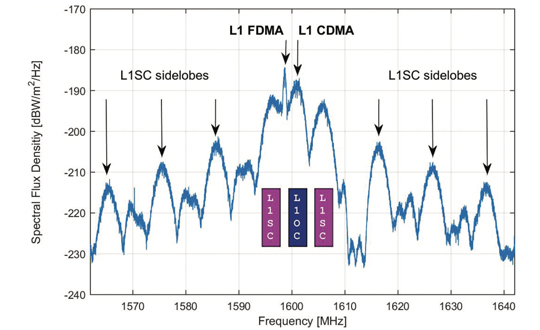
Figure 1. GLONASS K2 spectrum of the L1 frequency band. The different components of the L1 CDMA signal are indicated by colored boxes. L1SC: secured signal. L1OC: open service signal. (All figures provided by the authors)
Frequency spectra of R803, including these new signals, are shown in Figures 1 and 2. They were measured with the 30 m high-gain antenna of the German Space Operations Center (GSOC) in Weilheim, Germany, on Jan. 17, 2024. The largest and sharpest peak in the L1 band at 1,598.625 MHz originates from the 0.5 MHz binary phase-shift keying (BPSK) FDMA signal. The center peak of the L1 CDMA signal is located at 1,600.995 MHz. It is related to the L1 open service signal consisting of a data component (L1OCd) and a pilot component (L1OCp). L1OCd and L1OCp are combined by time-division multiplexing. The peaks that are ±5 MHz away from the L1 CDMA center frequency are introduced by the binary offset carrier (BOC) modulation of the secured L1SC signal. Prominent L1SC side lobes are visible ±15, ±25 and ±35 MHz offset from the center frequency. A quadrature phase-shift keying (QPSK) modulation is used to combine the L1OC and L1SC signals. The local minimum between 1,610 MHz and 1,614 MHz is caused by a notch filter onboard the satellite to protect radio astronomical observations of the Hydroxyl spectral line at 1,612 MHz.
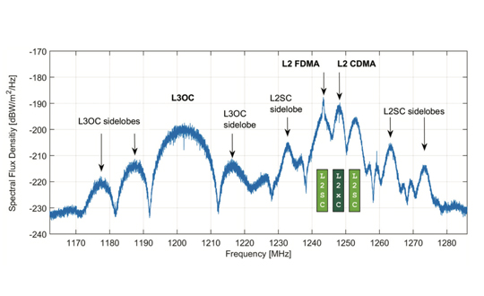
Figure 2. GLONASS K2 spectrum of the L2 and L3 frequency bands. The different components of the L2 CDMA signal are indicated by colored boxes. L2SC: secured signal. L2xC stands for the time multiplexed L2OCp and L2 CSI signal. (All figures provided by the authors)
The L2 CDMA signal is composed of a signal for service information (L2 CSI) and the pilot open service navigation signal (L2OCp). As for L1, these two signals are time-division multiplexed and combined with the secured L2SC signal by QPSK. The left main lobe of the L2SC signals coincides with the L2 FDMA center frequency of 1,243.375 MHz. Both, the L2 CSI, as well as the L2OCp signal, contribute to the peak at the L2 CDMA center frequency at 1,248.06 MHz. The L3 CDMA signal is composed of 10 MHz BPSK data (L3OCd) and pilot (L3OCp) components resulting in a broad peak at 1,202.025 MHz.
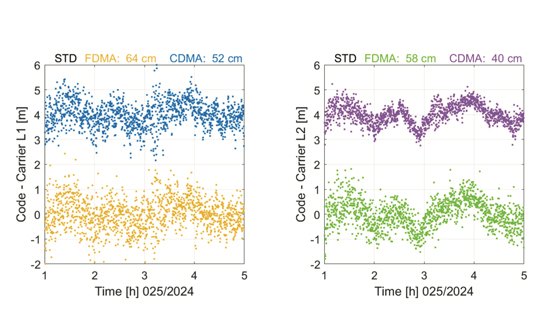
FDMA and CDMA signals of GLONASS R803 were tracked with a JAVAD TRE_3S receiver with a prototype firmware located at GSOC in Oberpfaffenhofen, Germany. Figure 3 shows the differences between pseudo range and carrier phase observations for the FDMA and CDMA signals in the L1 and L2 frequency bands. Long-term ionospheric effects were removed by a second-order polynomial. Thus, remaining effects include short-term ionospheric variations, multipath, and observation noise. The standard deviation of the code–carrier combination is, in general, at the half-meter level. Due to their advanced design, the CDMA signals show an improved performance by 18% for L1 and even 31% for L2 compared to the legacy FDMA signals.
Figure 3. Code – carrier for GLONASS R803 FDMA and CDMA signals: L1 (left) and L2 (right). A second order polynomial has been removed and the CDMA signals are shifted by 4 m. (All figures provided by the authors)
Further launches of L1 and L2 CDMA-capable GLONASS K2 satellites are planned for the upcoming years. A constellation of at least 12 satellites is expected for 2030. To guarantee backwards compatibility, these satellites will also transmit the L1 and L2 FDMA signals. Further improvements in positioning accuracy are expected due to improved satellite clocks and inter-satellite laser ranging.
Russian Space Systems (2016), GLONASS Interface Control Document: Code Division Multiple Access Open Service Navigation Signal in L1 frequency band. Russian Rocket and Space Engineering and Information Systems Corporation, Joint Stock Company.
Russian Space Systems (2016), GLONASS Interface Control Document: Code Division Multiple Access Open Service Navigation Signal in L2 frequency band. Russian Rocket and Space Engineering and Information Systems Corporation, Joint Stock Company.
Manufacturers
GNSS data used in this article were collected with a JAVAD TRE_3S receiver. The spectral overviews were captured with a Rohde & Schwarz FSQ26 signal analyzer.
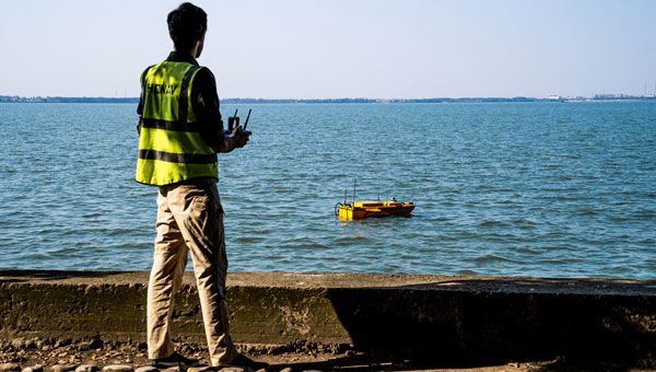
The Icelandic Road and Coastal Administration (IRCA) has commissioned the Dutch UAV manufacturer Acecore to map the extent and aftermath of the Eldvörp-Svartsengi volcanic system eruption using its high-end UAV solutions. Grindavík, a fishing village on the Reykjanes Peninsula in southwestern Iceland, has only recently welcomed residents home following a series of earthquakes. However, the area is still not completely at ease, with the latest reports saying that a nearby magma chamber could again erupt near the village.
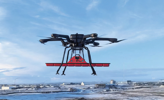
Acecore’s new hybrid drone model. (Photo: Acecore)
“Acecore drones are particularly suitable for use under tough circumstances,” said Jorrit Linders, founder and CEO of Acecore, on the Dutch public-service radio station NPO Radio 1. “The drones can operate in severe weather conditions, such as wind force 7 or 8, temperatures well below zero and hail and snow showers. This is due to their robust frame, their strong design and the right components. The robust construction is produced entirely in the Netherlands. This, combined with a continuous flight time of 2.5 hours, is essential for projects such as the volcanic eruption in Iceland.”
Acecore has been mapping in the region near Grindavík for four weeks as of March 2024. The surveys were done not without challenges and risks, as they involved operating in areas that had not yet been declared safe. The high workload and poor weather conditions forced the on-site team to rotate every five to six days. Linders was able to train both Acecore employees and pilots working for The Icelandic authorities on how to properly conduct aerial surveys to collect the relevant data effectively.
Lava flowing down the main road toward Grindavík. (Photo: Acecore)
Acecore developed and deployed a hybrid version of its Noa UAV, which already was used by the Icelandic authorities. The gas-electric platform was able to achieve flight times of 132 minutes with the Radarteam Cobra ground penetrating radar (GPR) of 5.2kg. The Noa Hybrid UAV has liquid heat management for its gasoline boxer engine, making it highly capable of dealing with Icelandic temperatures of up to -12°C. It uses a dual antenna and dual-band GNSS high-precision receiver to accurately measure yaw using GPS, so as not to be affected by electromagnetic interference from power lines and metal structures while mapping the village.
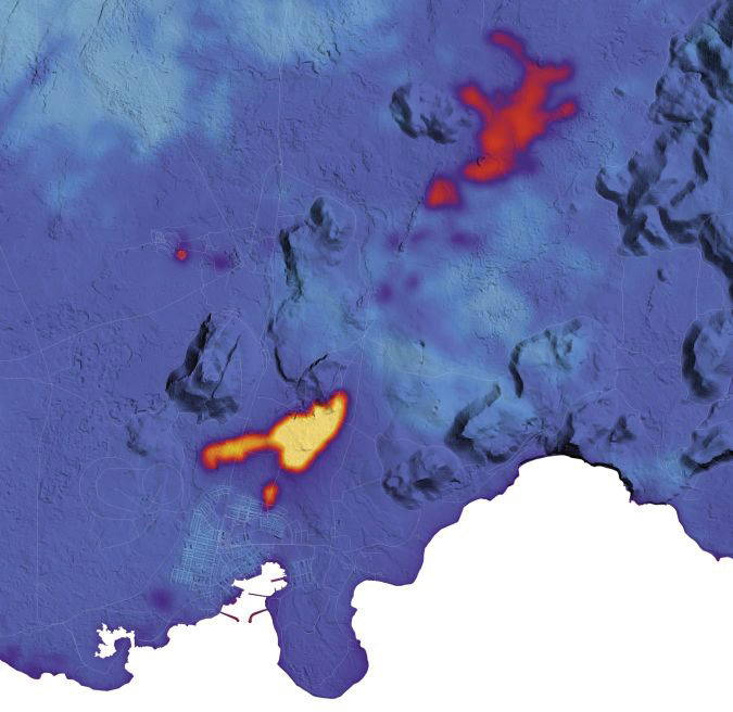
This map indicates the location and extent of recent activity using data acquired on January 16, 2024, by the TIRS-2 (Thermal Infrared Sensor 2) on the Landsat 9 satellite. The data is overlaid on a digital elevation model of the area. (Photo: NASA Earth Observatory/Lauren Dauphin, contains Landsat data from the USGS)
The UAV flights take off from fixed locations to perform their automated missions: scanning the affected area to collect all data needed by the Icelandic authorities. This involves data generated by a GPR sensor mounted under the UAV.
“We take a kind of X-ray of the ground as the basis for accurately mapping the subsidence and cracks,” explained Linders. “This then allows the Icelandic scientists to do a careful analysis of the area.” The GPR technology allows cracks to be scanned and underground fissures and shifts to be identified so scientists can predict where more eruptions are likely to occur and assess the safety of the location.”
The GPR technology allows cracks to be scanned and underground fissures and shifts to be identified so scientists can predict where more eruptions are likely to occur and assess the safety of the location.
The ongoing efforts in Iceland are a testament to Acecore Technologies’ dedication to pushing the boundaries of what is possible with UAVs. As they continue to map the area around Grindavik, their expertise and technology are not just tools for assessment but also a sign of hope for a community looking toward recovery. There is more work to be done, said Acecore’s Youri van Helden, “We haven’t put our snow boots in storage yet.”
K1000ULE in flight. (Photo: Kraus Hamdani Aerospace)
There was a lot of press noise in December 2023 about DOD’s Replicator program– which has been interpreted as a project to field thousands of U.S. UAVs to counter a perceived weakness in the face of China’s options for waging UAV war. Then there was a move by the Replicator program office to better explain its approach. It was reported as having at least four concurrent elements:
Encourage U.S. industry to conceive and implement ways to overcome the new aspects of conducting war and possibly use more UAVs more often.
Let China know that the United States is already on the move to not only keep up with but exceed Chinese capabilities.
Overhaul the extremely burdensome and slow existing DOD procurement machine to make large, rapid acquisitions.
Invigorate DOD military services to quickly adapt to find ways to use UAVs in multiple offensive and defensive roles.
Presumably, lessons learned in Ukraine — where both sides have been throwing both improvised and specially designed explosive drones at each other — and U.S. Red Sea encounters with Houthi rebels — have helped to frame some of Replicator’s objectives.
Anyone who has labored through a DOD request for proposal (RFP), RFP response, competitive re-bid and maybe even more competitive re-rebid that potentially led to months of questions and waiting leading to an ultimate reward or disappointment can imagine what hoops the procuring agency had to jump through. They can also imagine the time that elapsed from the definition of a requirement to a written firm procurement specification, and approval of a procurement package.
Never mind the allocation of procurement staff, establishing a budget and then processing of possibly multiple responses – this is a complex, arduous and time-consuming task for both industry and the procurement agencies. With help from the Defense Innovation Unit (DIU), it is anticipated that acquiring and fielding thousands of commercially available autonomous drones will now go quicker.
Imagine the inertia needed to change the way that military services use the materiel they’ve acquired and how difficult it might be to change what is bought and how it is used at the very front end of a war effort. When the opposition chucks many, small, inexpensive, airborne bombs at you and you do not have an immediate answer other than a limited number of multi-million-dollar interceptor missiles, it can be very painful. Matching drones with drones is essential.
Replicator was initially envisaged as a $1 billion program over two years to counter this and other problems for the warfighter.
On March 23, Congress finally passed the FY 24 $825 billion defense spending bill — almost six months late — which contained $200 million for Replicator, and DOD began to scramble to find an additional $300 million for the program’s first year. It should work out as there is money currently unspent from the FY23 budget that DOD has already requested Congress to re-allocate, and there is only a little more than six months left for this fiscal year anyway.
It is rumored that AeroVironment, with its Switchblade 600 semi-autonomous, one-way Kamikaze UAV, may benefit from an early Replicator procurement. With an anti-armor charge, Switchblade weighs about 50 lb and can fly for 24 miles and up to 40 minutes before engaging its target, allowing adequate time for manual intervention.
The U.S. Navy has selected a solar-powered UAV from a California start-up because it is the best demonstrated commercially available option for their Marine Corps scouting group.
The K1000ULE from KHAero in Emeryville, California is a long-range reconnaissance UAV.
With 24-hour flight endurance, extremely quiet and virtually radar-undetectable, the UAV provides the Marines with a suitable scouting tool – almost a launch-and-forget facility for day and night, most weather recon activities. It is also a relatively low workload for a team of only three to five personnel to transport and operate.
With vertical take-off and landing capabilities, the K1000ULE is ideal for covert autonomous operations from unprepared areas that a small squad might secure. The mission equipage includes full-motion video with target identification and classification and a secure communications systems.
With anti-jam, anti-spoofing multi-constellation GNSS, the vehicle can operate reliably in most signal-denied areas. It finds and automatically uses thermal columns to soar up to 20,000 ft and loiter undetected. It is capable of beyond visual line of sight (BVLOS) flight, can carry ADS-B for airborne collision avoidance and can be operated in swarms by a single operator when required – quite some UAV!
The Kratos XQ-58A Valkyrie Wingman UAV was developed to work with and on-behalf of high-end airborne assets, such as the F-22 and F-35, and is termed an ‘attributable’ adjunct to these ~$90 million fighter/ground-attack aircraft. Autonomous, driven by AI, and stealthy, the jet-powered UAV carries General Aviation electronics, along with other military communications. It is said to cost in the $5 to 10 million range — which makes it somewhat disposable if it is sent into a “tight or risky” location from which its fighter escort should hold back.
With a 3,000 miles range, 45,000 ft ceiling and carrying capacity of up to 1,800 lb of under-wing armaments, the aircraft can be controlled from an accompanying aircraft as a “Loyal Wingman,” or from the ground and be dispatched to carry out an autonomous, independent mission, requiring approval by a person to release weapons.
The XQ-58A was recently flown with two U.S. Marine Corps F-35 fighter jets at Eglin Air Force Base, Florida to demonstrate the capability for electronic attack and to fly alongside these fifth-generation high-end aircraft. The UAV autonomously detected, classified, and positioned multiple simulated targets during the exercise and provided target-tracking information to the F-35s.
The “Loyal Wingman” concept is still being developed and there are other companies, including Boeing Australia, flying competing prototype UAVs.
So, a more mil-spec tone to this month’s UAV updates, nevertheless a short recap of recent interesting unmanned, autonomous aircraft developments.
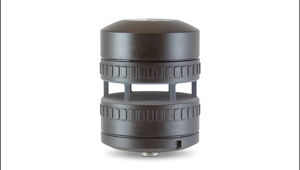
Inertial Labs has integrated the FT Technologies FT743-D-SM Acoustic Resonance air speed sensor into its inertial navigation systems (INS).
This integration aims to improve the accuracy of horizontal air speed estimation for multi-rotor UAVs, even in GNSS-denied environments. The FT743-D-SM airspeed sensor is a digital anemometer-based solution that can estimate airspeed incoming from any direction using acoustic resonance technology, which is immune to vibration and external acoustic noise. The airspeed magnitude and direction allow the INS to estimate horizontal air speed in the longitudinal and lateral axes.
The INS receives aiding data from the dual-axis airspeed sensor and experiences significantly less position drift compared to a dead reckoning alternative in GNSS-denied environments, the company said. The system can be used in mission-critical roles in multiple military or defense applications, as well as in civilian applications such as wind energy, marine navigation, UAVs and dynamic positioning systems.
An exclusive interview with Michael Gavart, CTO of M3 Systems.
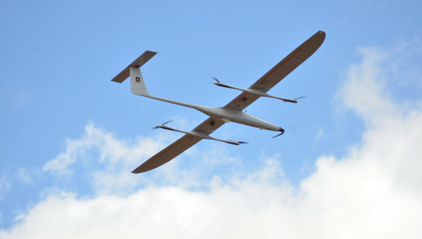
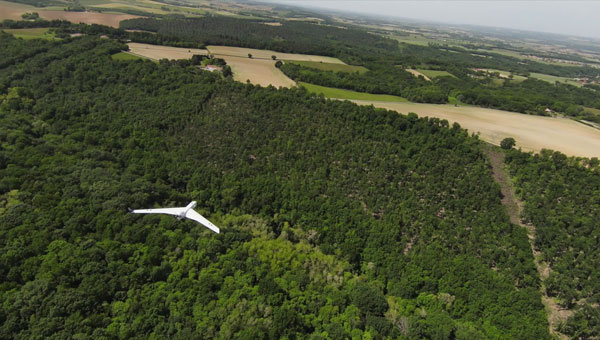
The Boreal UAV ready for departure on a maritime mission scheduled to last several hours. (Image: M3 Systems)
What is your role?
I am responsible for all the technical developments on the UAV.
Please describe it.
It’s fixed wing. It has a 4 m wingspan, a maximum takeoff weight of 25 kg, a carrying capacity of up to 7 kg and up to eight hours of flying time. What is special about this UAV is its size and the size of the payload bay, which is large enough to hold different kinds of payloads.
Do you have different versions?
We have a surveillance version, called BOREAL ISR, that has been used for several projects. Another use case for this UAV is to embed scientific payloads. For example, we had several campaigns for meteorology in partnership with Météo-France in the Indian Ocean to study cyclones and another in the Caribbean Sea to study tropical convection. We did several large scientific campaigns with Météo-France.
Most of the payloads we integrate are for scientific testing. Some of them are for cartography in the visible or infrared domain and other kinds of payloads involve radio frequency testing. Among them, we have, of course, GNSS.
The project we conducted in 2023 was a demonstration campaign for the operational use of this surveillance UAV. The campaign occurred from July to November 2023. It consisted of 20 five-hour flights, three of which were at night. In total during that campaign, the UAV flew more than 100 hours for about 8,000 km and captured data from about 20,000 sq km. This made it possible to identify hundreds of boats fishing illegally. In some cases, the country’s navy intervened and the UAV took live video of the operation to help analyze the scene.
The UAV also flew many operations over the tropical forest, some of them at night, which made it possible to identify some recent mining activities in sites that had already been destroyed some months before.
Another subject was forest fires. During one flight, we identified more than 20 forest fires and the firefighters were able to prioritize where to intervene to fight the fires.
What about flights beyond visual line of sight (BVLOS)?
The radio link enables operators to fly the UAV from up to 100 km from the ground control station, provided that we remain in radio line of sight (RLOS) conditions. Additionally, the UAV has a satellite communication system to fly beyond RLOS in some cases. For some scientific missions, the UAV was flown beyond RLOS conditions using satellite communications, and we could fly up to 250 km from the ground control station.
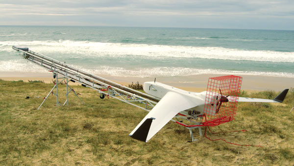
The Boreal UAV is currently deployed for various kinds of terrestrial applications. (Image: M3 Systems)
When was this UAV first available? What is the market for it?
The first big campaign occurred in 2019, for scientific meteorology over the Indian Ocean. The BOREAL drone LAB, a scientific meteorology drone, was ready to operate in 2014.
A second product, (maritime and terrestrial surveillance use cases) was developed and ready to operate in 2021.
Are you selling large numbers of this UAV or only for some special missions?
Several of them have been sold to laboratories for science. From now on, we sell hours of flights as a service on the ISR product. Each drone is used for specific missions (surveillance in particular).
You rent it out instead of selling it?
We sold UAVs to laboratories and now we sell hours of flights as a service. We don’t rent the product. We have a drone fleet that allows us to conduct several missions throughout the year.
How does all this fit in with M3 Systems’ other products and application areas?
GNSS development requires testing radio frequencies in flight. Our UAV is very useful for testing GNSS payloads. We also have a project to provide payloads for satellites. It is an intermediate step for testing these payloads in the air. The BOREAL drone also leverages the group’s expertise in ATM/UTM, making its integration into the airspace seamless.
What GNSS receiver is on the UAV? Also, what correction networks does it use?
The drone embeds a standard GNSS receiver and uses it for its own navigation needs without corrections service. However, through the PASSPORT project the objective was to demonstrate the added value of OSNMA encryption in the Galileo signal, particularly its anti-spoofing capabilities. To assess this, we needed to conduct a spoofing attack on receivers with the OSNMA functions. We used a Septentrio Polar X 5 receiver. Due to safety concerns, this could not be performed on the drone during flight. Instead, we recorded the IQ signal onboard the drone during the flight campaign and later replayed it in the lab for the receiver. During the replay, we introduced spoofing while OSNMA was disabled on the receiver and showed that spoofing was easily achieved. When enabling the OSNMA service on the receiver, spoofing was still possible but the authentication key was not received, indicating that the signal was not trustworthy.
An exclusive interview with Brandon Malatest, co-founder and COO of Per Vices
What is your title and role?
I’m one of the founders of Per Vices. My friend and I started the company a long, long time ago. I’m a physicist. I attended the University of Waterloo, graduated with an honors degree in physics, and have been working with Per Vices for more than ten years. My role has shifted from doing the actual engineering work to running all the other elements of the company, because as we continue to grow, we can’t be doing everything and that was the logical break. So, I definitely have a technical background, but I’m not the one who’s designing the products anymore.
When was the company founded?
In 2006. Our first commercial product was in 2012. We specialize in designing high performance software-defined radios. These are full transceivers that are used across a very wide range of markets: spectrum monitoring, electronic warfare, MRI, radar, test and measurement markets, communications, radio links — you name it and we’ve done some work in that space. The whole idea behind software-defined radios is that they are very flexible systems. So, with the same hardware platform, you can change the software or firmware, and have it used for a completely different application.
Wonderful. By the way, I grew up among physicists. My father was a physicist for 60 years, the last 35 of which at Brookhaven National Laboratory on Long Island. My paternal grandmother was one of the first women in Europe to get a Ph.D. in physics and math and Enrico Fermi was one of her thesis advisors.
Why is SDR important for autonomous systems?
There are eight major points that I’d like to hit on.
Flexibility. Software-defined radios are reconfigurable, which means that the same hardware platform can be used for many different communication protocols, across different radio bands with varying bandwidth. That makes them very flexible for interfacing with other types of systems. So, in terms of the autonomous systems, there are a number of different wireless devices that need to be interoperable.
SDRs are very flexible radio platforms. They’re designed to have very wide operating frequencies with varying bandwidths so as to replace what used to be done in hardware through dedicated DSP chips, replacing dedicated hardware with a software-based architecture.
From a flexibility standpoint, that means that software-defined radios usually use some type some type of DSP mechanism, like a field programmable gate array (FPGA). That allows the SDR itself to process all types of different signals across varying frequencies and manipulate them in different ways. Anything that’s wireless is basically converting an analog signal to a digital signal and then performing some action on that digital signal. SDRs do that in a different way. They still have the hardware that’s used for tuning, but on the software side the decoding and processing happens. In a traditional FM radio, you have everything done in hardware: it has a dedicated tuning block, a dedicated DSP that does the demodulation, and it spits out the audio. So, the same way that computers, way back in the day, were designed and built from the ground up with one sole purpose — whether it be word processing or running complex trigonometry.
But now, if you look at the utility of computers, it is the fact that you can run different software applications on them. So, the same idea is with SDR. Traditional radio devices were built from the ground up for a single application. Now, SDRs are like a modern-day computer, where you can do basically anything within that tuning frequency. Also, just like with a computer, you change the software and use it for different applications.
Flexibility is definitely one of the most important elements. It allows the user or the system integrator to have an SDR that can adapt to different communication standards and frequency bands. This flexibility is crucial for autonomous systems operating in dynamic environments, where communication requirements may change. So, if you’re suddenly needing to change from operating at 2.4 GHz to operating at 5 GHz due to spectrum congestion or something along those lines, an SDR can do that with the same hardware platform.
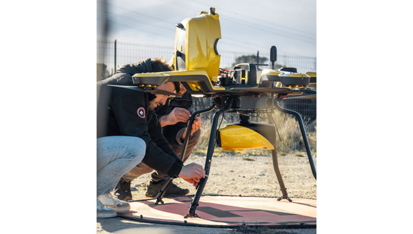
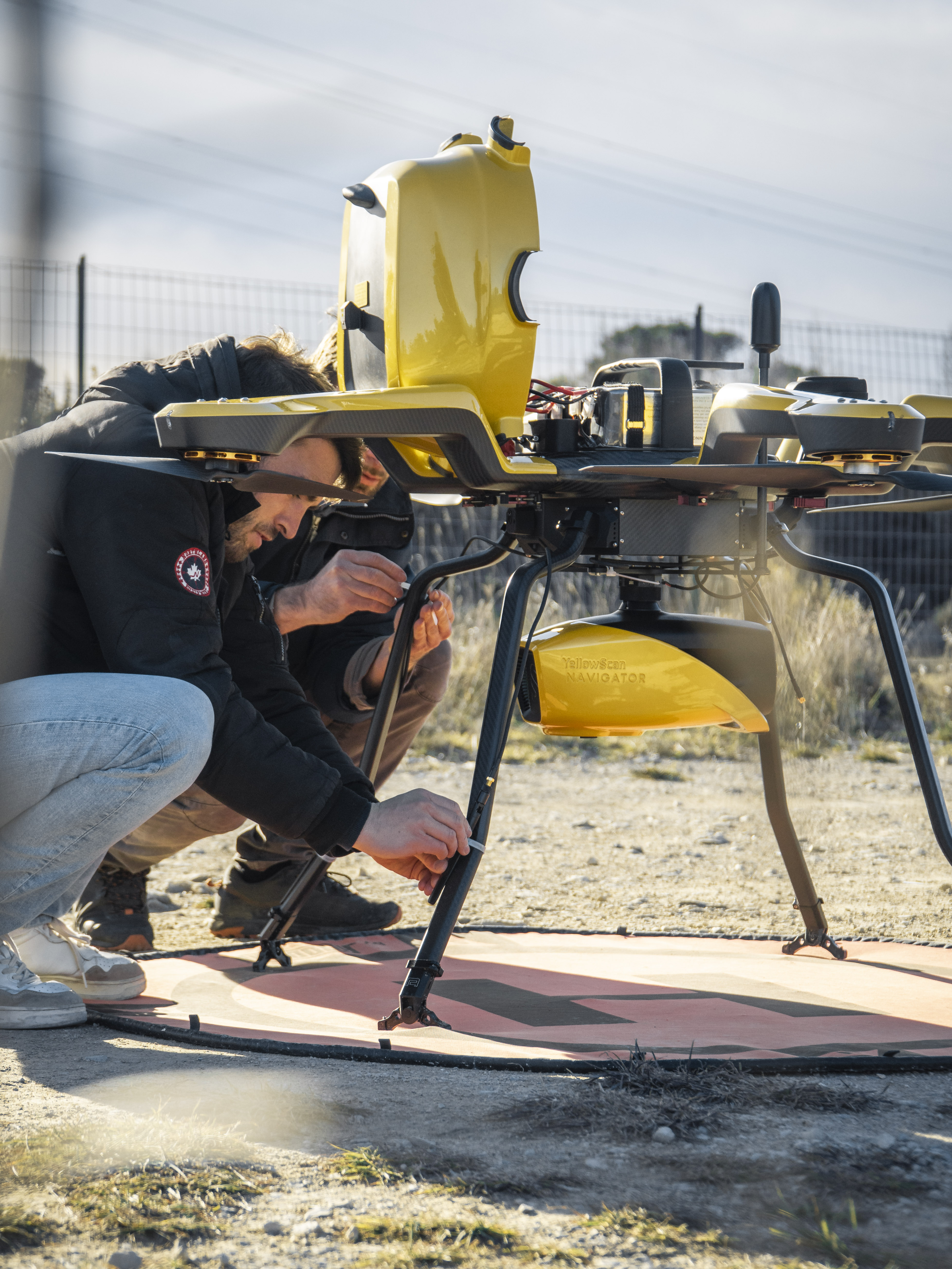
YellowScan’s bathymetric lidar product, the Navigator, mounted on the Noa from Acecore. This full waveform lidar system ensures continuity between underwater points and the surrounding terrain.(Image: YellowScan)
Adaptive communication. Because SDRs tune to various frequency bands and then all the decoding is done in software, they can support different communication standards with the same hardware platform. That enables autonomous systems to communicate effectively with various entities in the environment, such as sensors and additional equipment.
Spectrum awareness. We can call it smart SDRs, or SDRs where you can integrate with AI or you can do your own pre-programming on it. You can monitor different parts of the spectrum to see which is the least congested, so that you can have a clear frequency band of operation to communicate or to use that information for passing data to and from sensors or a command and control system or anything.
Going back to the hardware component, the FPGA onboard acts as a digital signal processing unit. So, SDRs have those onboard DSP units — usually, FPGAs — and that allows for such things as signal modulation and demodulation filtering, waveform generation. All this can be done in real time. It also allows for all the sensor data to be processed very effectively and quickly, with significantly reduced latencies.
Reduced hardware complexity. This relates to putting it all together. When you have the DSP unit and the flexible hardware platform, you don’t really need anything else. So, you can use that SDR to minimize the complexity associated with the overall system. When you’re using multiple disparate technologies, it does become challenging to make sure that they’re all integrated well with one another and work well together. With SDRs, you can really simplify that, that hardware complexity. Then, because SDRs are programmable and customizable, they can be used all the way from prototyping to production. By changing different software or firmware elements associated with the SDR, you can have it operate in different ways. So, if you want to prototype a different communication band that may work better for some environments, you can do that very easily without needing to re-spin new hardware upon new hardware upon new hardware, which gets to be costly and time-consuming.
Remote monitoring and control. SDRs can be set for what we’ll call static operation, where they will perform only one task, to prevent tampering. You can also set them to be updated over the air or through some type of network. So, again, the flexibility is quite significant and it’ll allow you to mitigate different challenges where some of the systems might not be able to be controlled or interfaced regularly from a hardware perspective. That can all be encrypted.
How does your module interface with autonomous platforms?
The analog connection — to external amplifiers or filters, if you need to have very clean use of a particular part of the spectrum — is via SMA connections, which are pretty standard in the industry. On the digital side, there are two different ports. One is an out-of-band communication interface. That’s just a 1 GB Ethernet port that is very common across the entire industry and is used for configuring the SDR. Again, that’s out of band, so you’re not causing any interference with the actual operation. The other one is the digital interface for sending data to and from the system. That can be done over a 10 G interface, a 40 G interface or a 100 G interface, depending on the platform, how much bandwidth you need, etc.
What is your market at this point?
We don’t discuss our customers specifically, because often they are either very large commercial entities that don’t like to have their names disclosed or they are defense prime contractors that don’t want their names to be disclosed either. So, I can’t really get into customer specifics. What I can say, however, is that our SDRs have been deployed in support of many applications, across such systems as radars, early warning systems, MRIs, signals intelligence, spectrum monitoring, low latency wireless links, and test and measurement. There’s definitely been interest in having our systems deployed for a variety of spectrum monitoring applications on UAVs or other autonomous systems where dynamic spectrum control is important.
That’s exactly where our high-performance products fit the bill, because they have a very wide tuning range — from near DC up to 18 GHz, and it offers up to 16 radio chains, where you can monitor every different part of the spectrum continuously.
Are your systems deployed primarily on land, sea, or air platforms?
Primarily on land and air vehicles. Our system is not miniaturized for robots. When you get into sea, it does become a little bit more challenging.
What about small UAVs?
It depends on how small you’re talking about. Often, those small UAVs will use a card, as opposed to an entire system. So, it’ll be a special PCB, that performs just one dedicated function. For some of the UAVs that demand the highest performance, they usually can support a payload of one of our SDRs. They’re not small, but they definitely can support the size, weight and power of one of our higher end SDRs, which are 19” 3U form factor rack-mountable solutions.
What are a couple of use cases or scenarios for autonomous systems?
Interoperability would probably be one of the biggest that keeps creeping up.
Swarms?
Yes. Basically, the ability for the different elements within a system to communicate with one another. The idea would be having some sort of AI or machine learning applied to autonomous systems, which is the future. The problem right now with it is that many of the autonomous systems utilize different communication protocols. That makes it very challenging to have a single set of controls to interface with them.
For us, one of the use cases would be for SDR to be the intermediary. So, capturing the digital data from each of those different frequencies and combining them into one source for that machine learning or AI to utilize. Imagine that you had sensors that were being used for short range radar, long range radar, communications, etc. You will be across the L band, the C band, the 2.8 GHz band, the 5.8 GHz band. You will be across several different protocols. Not all those systems will play well with one another. So, where we fit in is communicating with all of those disparate devices and converting all that data into a digital domain for additional processing to take place.
Another scenario is what we see a lot in our customers who are doing command and control for various tactical systems and want a single platform on their side to interface with all these separate RF devices.
CHCNAV’s Apache USV, made of macromolecule polyester carbon fiber and Kevlar fiber-glass, can be carried by a single person. (Image: CHCNAV)
Bridges are essential components of our transportation infrastructure, facilitating seamless travel and connecting communities. The construction and maintenance of a bridge is an ongoing process, influenced by a variety of natural factors, including topography, geology, meteorology and hydrology. To protect the foundations and ensure the structural integrity of bridges, it is critical to continuously monitor bridge piers with a focus on providing consistent data support. For this project, the acquisition of 3D point cloud data of the riverbed surrounding a bridge is essential for the long-term safety monitoring of its abutments.
The Challenge of Traditional Surveying Method
Traditionally, bridge pier surveys are conducted using manned boats equipped with multibeam sonar — a method that, while mature, faces several challenges:
1. Significant safety hazards. Survey areas are prone to tidal changes, high winds, waves, and traffic from passing vessels, which can often create dangerous working conditions. Stone ridges along the riverbanks, potentially hidden during high tide, pose additional risks to manned boats surveying near bridge piers.
2. Low operational efficiency. After a typhoon, the timeline for surveying is tight. However, setting up and calibrating multibeam sonar equipment on manned boats is time-consuming. Operations in shallow areas, such as riverbanks and near central river sandbars, are limited to short periods of low tide, requiring strict adherence to schedules.
3. Poor data quality. Multibeam surveying requires overlaps of more than 20%. Accurate route keeping by manned boats, critical to multibeam surveying, is often compromised by environmental conditions and operator experience, resulting in poor data quality. In addition, GNSS signal reception under bridges is poor, affecting positioning accuracy and thus the integrity and efficiency of data collection.
4. High operational costs. The lack of specialized underwater topographic survey vessels requires the rental of traditional manned boats, which increases project costs.
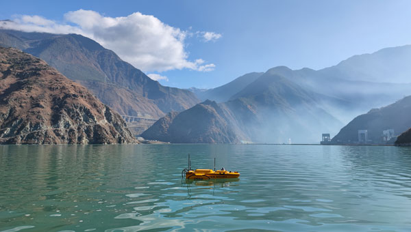
A USV can operate where it would be dangerous or inefficient for a manned boat. (Image: CHCNAV)
The CHCNAV Solution: Efficient Autonomous Surveying
To overcome these obstacles, one bridge project team implemented an innovative solution: the use of the Apache 6 unmanned surface vessel (USV) coupled with a NORBIT multibeam echosounder and an iLiDAR 3D laser scanner. This integration results in a system that is not only lightweight, compact, and easy to install and operate, but also portable and energy efficient.
The Apache 6 USV, with its all-carbon fiber hull weighing only 15 kg, combines lightness with durability. Its modular design simplifies logistics and transportation, while its ability to withstand offshore conditions and automatically follow pre-determined routes enhances operational efficiency. The system synchronizes surface and underwater data, with beams capable of scanning shallow flats and channel slopes. The echosounder and iLiDAR share position, heading and attitude data to optimize cost efficiency.
The iLiDAR 3D laser scanner features an ultra-lightweight design, with the main unit weighing less than 3 kg. Its high level of integration, requiring only a single cable for full-surface data access, and compatibility with leading multi-beam data acquisition and processing software underscore its utility.
Advantages of Using USVs
Compared to traditional manned boat surveys, the Apache 6 USV’s integration of surface and underwater sensors offers several advantages, including high integration, compact size, safe unmanned operation and lower operating costs. In addition to ensuring the safety of personnel and bridge structures, it increases survey efficiency in complex environments. Using this autonomous survey system, two project engineers were able to create a high-resolution 3D point cloud model of the riverbed scour around the bridge piers at a low operational cost. This dataset is invaluable for ongoing safety monitoring of the bridge piers, facilitating proactive maintenance and ensuring the long-term stability and reliability of this critical transportation infrastructure.
Marking the lines of a soccer field in Vejle, Denmark using a TinyLineMaker Pro X. (Photo. Unicore)
Robotic technology is increasingly integrated into daily life, including applications such as delivery vehicles, automated lawn mowers and line painting robots. Among the critical factors shaping the navigation capabilities of these robotic machines, precise positioning and heading are paramount. Leveraging Unicore’s high-precision GNSS real-time kinematics (RTK) module, TinyMobileRobots, a Danish company, has developed advanced autonomous systems that excel in navigating complex environments.
RTK technology, which greatly compensates for errors in GNSS satellite signals, enables real-time positioning accuracy within 1 cm to
2 cm. The RTK algorithm in Unicore’s UM960 multi-constellation, multi-frequency GNSS module gives it high reliability, precision and fix rate.
Sports fields grounds maintenance teams at schools, parks, housing developments and other locations often need to refresh line markings, which is a very labor-intensive and challenging process. In search of a more rapid and efficient solution, the team marking the lines of a soccer field in Vejle, Denmark, opted for TinyMobileRobots’ autonomous system. This system is becoming popular among groundskeeping teams due to its ability to queue multiple pitches for sequential marking without recalibration, maximizing productivity. It also alerts users when it is running low on paint and estimates its remaining time and distance. The enhanced capacity afforded by the robot’s efficiency also allowed the team to explore new service offerings, such as providing line marking services to other organizations.
The TinyLineMaker Pro X estimates when it will run low on paint and alerts users. (Image: Unicore)
For outdoor robotic applications, GNSS technology’s levels of accuracy range from sub-meter positioning to decimeter and centimeter levels in real time, depending on the specific application. When integrated with complementary sensors such as inertial navigation systems (INS), vision, and radar, robotic navigation can be effectively realized across diverse and complex environments.
Several technologies — ranging from very mature to nascent — are converging to make autonomous vehicles and devices more useful, efficient, and reliable than ever. They include real-time kinematic (RTK) GNSS, inertial navigation systems (INS), cameras, and radar for navigation; cameras, lidar scanners, multibeam echosounders, and a variety of other sensors for data collection; software-defined radios (SDRs) for secure communications; and artificial intelligence (AI) to plan routes, coordinate the movements of multiple autonomous vehicles and devices (including “swarms” of UAVs), and analyze the data collected.
Read this cover story, featuring case studies from Unicore and CHCNAV, interviews with executives at Per Vices and M3 Systems, and images from Frontier Precision and YellowScan.
Iridium STL is being deployed by L3Harris to protect critical FAA data center infrastructure. (Photo: Iridium)
Iridium Communications has entered a five-year agreement with L3 Harris. Under the agreement, Iridium will provide its satellite time and location (STL) service to more than three dozen L3Harris-operated communications network backbone nodes and a similar number of Federal Aviation Administration (FAA) facilities throughout the United States.
L3Harris, responsible for operating a private network for the FAA, provides voice, data and video communications for the National Airspace System operations and mission support functions. Given the critical nature of timing synchronization within the L3Harris communications network, particularly for supporting various critical infrastructure applications, the Iridium STL service plays a pivotal role in the overall network timing architecture by eliminating dependencies on GPS as the primary timing source.
The solution for L3Harris includes compact devices provided by Adtran’s Oscilloquartz division, which are designed to receive Iridium STL signals. These devices seamlessly integrate into the network and meet nationwide network timing synchronization requirements.
In April 2024, Iridium acquired Satelles, a secure satellite-based time and location service provider.
Current state of the art multi-frequency GNSS receivers operate by receiving L1 first and then L5. L5-first is a viable answer to the call for more resilience in GNSS as is being discussed in government and technical circles to protect vital national infrastructure. It is suggested as part of “Toughening Category 4: Signal Alternatives” to protect, toughen and augment (PTA) the current GNSS systems described by Brad Parkinson’s article in the March 2022 issue of GPS World.
Paul McBurney
The need arises from attacks directed by bad actors on a large scale, such as electronic warfare, and on a more humane scale, by bad actors such as self-jammers and spoofers. On top of that, normal interference can cause desensitization and denial of service on GNSS receivers from myriad terrestrial and satellite communications.
The PTA plan presents the Denial Radius Reduction Ratio (DRRR) figure of merit and shows that a J/S increase of 15 dB produces a DRRR of 0.18. Whereas a receiver without this additional 15 dB of J/S could be denied fixing out to 1 km from a given transmitter, a receiver with an additional 15 dB J/S would be denied out to only 180 m from the same transmitter.
The improvement in terms of area is proportional to radius squared. The article identifies that the J/S capability is different among GNSS signals and the best performance is obtained with L5, mainly because it has the highest chipping rate. L1C has a code length of 10,230 chips, the same as L5, but it is spread over 10 msec and has the same chipping rate as L1 C/A.
There are currently 72 L5 signals between GPS, Galileo, BeiDou and QZSS transmitting the same physical layer features of 10.23 MHz chipping rate, 1 kHz overlay codes and higher transmit power compared to nearly all L1 signals with a 1.023 MHz chipping rate and lower transmit power. The combination of these features at L5 is close to achieving this 15 dB performance level over L1.
Unlike current hybrid receivers, L5-first survives L1 jamming. (Photo: Carkhe / iStock / Getty Images Plus / Getty Images)
One might conclude that the current start of the art of a receiver with both frequencies (aka, a hybrid L1+L5) has this resilience. However, the market does not currently offer the ability to directly acquire L5 signals overall use cases of GNSS assistance without first acquiring signals at L1. This means they can only achieve this resilience when the interference is encountered after acquiring and fixing at L1. As soon as the L1 is lost and the position and time uncertainty grow beyond the receiver’s capacity to autonomously search for L5 signals, the receiver is denied service at the interference level tolerable at L1. If you cut the receiver into L1 and L5 pieces, only the L1 side is capable of fixing autonomously. As noted by Dennis Akos et al. (“Testing COTS GNSS Receivers Using Only a Subset of Supported Signals,” ION JNC 2023), “support for several signals/frequencies provides integrity and robustness.” Specifically, “under jamming scenarios, signal diversity can allow a receiver to still generate an accurate position solution.”
Current receivers are not able to acquire L5 for reasons related to history, cost and power consumption. Historically, the promise of L5 accuracy was so attractive that it was added to legacy chipsets based on L1 even when it was only partially deployed. It was impractical at that time to require L5 acquisition when there were fewer L5 satellites than at L1. Cost and power are related to the fact that L1 receivers’ acquisition methods are sized to acquire the L1, E1, B1 and G1 signals. Memory and compute capacities, including the digital clock speed, are sized for slower chipping rates and hence shorter code lengths. At this performance level, conventional time domain correlation is adequate. Some receivers deploy frequency domain methods at L1 and achieve a lower cost and power than time domain methods with similar capacity. However, the L5 acquisition complexity with time domain correlation is 100 times more than L1 as its complexity increases with N2, meaning the cost and power to acquire L5 is out of reach. While using a time domain acquisition engine to acquire L5 may be possible for strong signals when the code and frequency search space is constrained for those signals, directly acquiring L5 with conventional methods would have serious shortcomings in many use cases.
Interestingly, the signal designers across all GNSS systems have cleverly designed the L5 signals so they can be easily acquired after acquiring their counterparts on L1. The L5 primary and secondary code is predictable based on learning the L1 primary code and navigation data bit phase. E5a and B2a primary and secondary codes can be predicted by learning the well-designed E1/B1 primary and secondary code phases that have the same total period: the combination of the 4 msec code lengths synchronous with 25 bits of secondary code are in phase with the E5a 100 msec overlay code. After an L1 fix with fine time, L5 can similarly be directly acquired easily with limited searching.
“Seen & Heard” is a monthly feature of GPS World magazine, traveling the world to capture interesting and unusual news stories involving the GNSS/PNT industry.
A child reported missing in Robbinsville, N.J., was found in less than 10 minutes using a UAV equipped with a thermal camera, WPVI reported.
On the night of January 17, Robbinsville Police received a call reporting a missing child last seen running into a heavily wooded area. Officers dispatched the department’s UAV equipped with thermal imaging cameras, which allowed officers to quickly locate the missing boy through thick vegetation after dark. The child was unharmed, according to the report.
Photo: Maxar Technologies
Fire strikes Chile
Maxar Technologies has released satellite images showing the widespread damage caused by raging wildfires in Chile’s Valparaíso region. The fires have killed more than 122 people. The images show entire neighborhoods destroyed east of the resort town of Viña del Mar yet do not show active wildfires. The fires reportedly surged in the Valparaíso region, fueled by winds and an intense heatwave that has seen temperatures of around 40° C.
The UK government has introduced regulations establishing a 400 m UAV “no-fly zone” around prison facilities. The announcement addresses the escalating use of UAVs by criminals attempting to transport illicit items — including phones, drugs and weapons — into prisons.
The initiative is a response to the increase in the number of UAVs detected or sighted within prison grounds, which more than doubled between 2019 and 2021, according to a press statement from the UK government. The implementation of “no-fly zones” aims to enhance law enforcement’s ability to catch organized criminals in the act. Additionally, these measures are designed to prevent illegal aerial filming of prisons.
Photo: Bim / E+ / Getty Images
Back to the fields
GNSS jamming by the Israeli Defense Forces (IDF) has forced retired farmers in the Israeli settlement Mevo Hama to return to the fields. In an interview with CTech, local farmer Rami Laner shared that the younger equipment operators do not know how to operate the modern tractors for spraying or sowing tasks without the aid of their GNSS-based autonomous systems. With the IDF intentionally jamming and spoofing GNSS signals, civilians in the area are in search of alternative PNT systems to protect communities and maintain workflows.