“Seen & Heard” is a monthly feature of GPS World magazine, traveling the world to capture interesting and unusual news stories involving the GNSS/PNT industry.
By using location data and a username from a Lime rental scooter, police have identified a man caught on video scootering around a Denver, Colorado, neighborhood loading up on stolen goods from surrounding homes, reported 9 News. Police obtained a search warrant for the scooter’s location data and account information. The suspect appears to have used his real name when renting the scooter to conduct the burglaries. 9 News is not naming the man identified as the scooter user as he hasn’t been arrested or charged. However, a background check on his name revealed he’s currently wanted on two theft cases that occurred in 2022, also in Denver.
Doordashing goes wrong
Image: ProjectB/E+/Getty Images
A DoorDash driver followed his navigation system into a wooded area and then into a body of water while attempting to deliver an order to a residential neighborhood in Middleton, Massachusetts, reported the Daily Caller. After following the navigation system straight into water, the driver called police. The Middleton Police Department is now charging the DoorDash driver for “negligent operation of a motor vehicle” and has put in a request to suspend the driver’s license.
Researchers at the Jiangxi Nanfengmian National Nature Reserve in China are utilizing BeiDou during bird banding to monitor their migration period from September to October. Bird banding involves attaching customized tags to birds’ legs or wings to track their movements and patterns. Out of 614 birds, 36 are being equipped with specially designed positioning devices that will continuously transmit data for researchers to analyze migration routes, stopping places, and migration time, according to a nature reserve official.
More than 20 airline and corporate jets flying over Iran overnight on October 1, were targeted by spoofed GPS signals. The spoofed signals were sent from the ground, infiltrated the navigation systems of the jets, and steered them off course, reported The Times of India. According to the Ops Group, which runs a flight data intelligence crowdsourcing website, a majority of the GPS spoofing occurred in airway UM688 in Iran’s airspace. In response, the U.S. Federal Aviation Administration issued this warning to airlines: “Iraq/Azerbaijan — GPS jamming and spoofing poses safety risk.”
Originally developed for navigation and timing applications, signals from global navigation satellite systems (GNSS) are now commonly used for geophysical remote sensing applications, including observation of Earth’s surface and atmosphere using near sea-level ground stations as well as mountaintop, airborne and spaceborne platforms. GNSS reflectometry (abbreviated GNSS-R), which is the technique of using reflected signals to measure properties of Earth’s surface, has been a growing area of research and application for GNSS remote sensing. Notably, the Cyclone Global Navigation Satellite System (CYGNSS) satellite mission produces delay-Doppler maps (DDMs) that are used to monitor ocean surface wind speeds during hurricanes. Meanwhile, terrestrial and airborne GNSS-R has been used to monitor soil moisture, snow depth and vegetation growth. One area of increasing interest is precision reflectometry using signal carrier-phase measurements. The first attempt to perform precision (phase) altimetry over sea ice using GPS reflectometry measurements from the low-Earth orbiting TechDemoSat-1 was reported by researchers in 2017. Subsequently, researchers demonstrated the use of reflections collected by a Spire satellite to perform altimetry over Hudson Bay and the Java Sea and how reflections off ice in the polar regions can be used to measure ionospheric total electron content over the polar caps. While these demonstrations of GNSS-R for precision carrier-phase-based reflectometry are promising, more work needs to be done to characterize when carrier-based altimetry is feasible and what challenges it faces.
To study the challenges associated with processing reflected and low-elevation-angle radio occultation signals, the University of Colorado (CU) Boulder Satellite Navigation and Sensing (SeNSe) Laboratory has deployed a GNSS data collection site on top of Mount Haleakalā on the island of Maui, Hawaii. Recent collection campaigns aim to use this site as a testbed for GNSS-R algorithms that utilize multi-frequency and multi-polarization measurements. Previously, we carried out delay map processing for left-hand circular (LHC) and right-hand circular (RHC) polarizations for L1 and L2 GPS signals. Those results validate the open-loop processing methodology and provide an initial assessment of the data quality. We observed that the received reflected signals show deep and rapid fading in amplitude. In the work reported in this article, we extend our assessment to triple-frequency GPS (L1CA, L2C, L5Q) signals and document our methodology for extraction of the signal carrier phase. Our initial results indicate that coherent signal phase extraction is challenging, and may not be feasible for this particular experiment setup. We discuss ways in which the experiment may be improved for the purpose of obtaining coherent ocean surface reflections in the future.
EXPERIMENT BACKGROUND
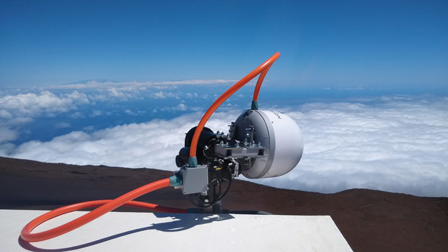
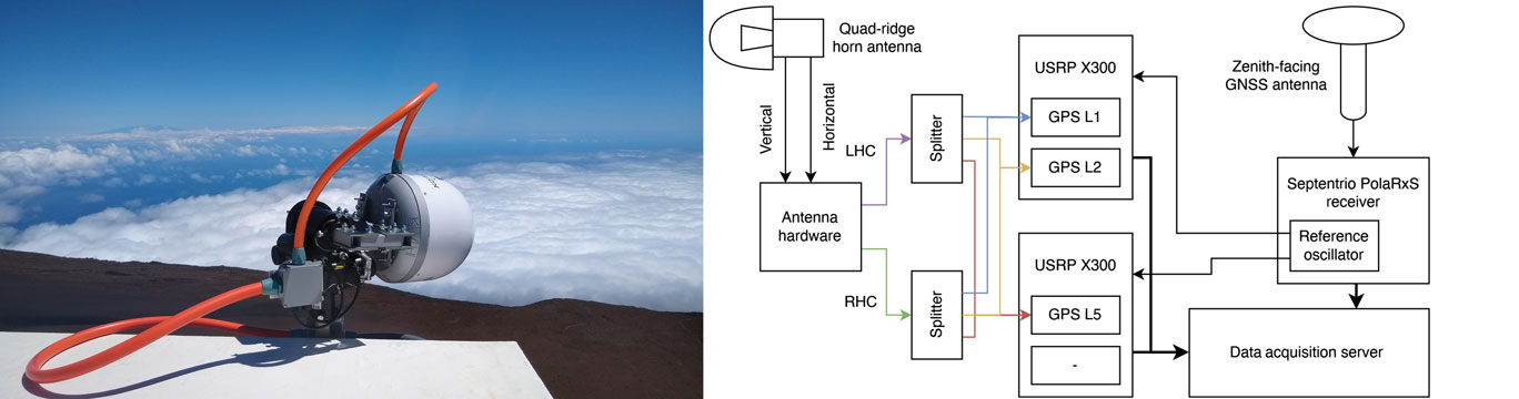
The current form of the CU SeNSe Lab Mount Haleakalā GNSS experiment was deployed in June 2020. It consists of a side-facing dual-polarization horn antenna, which is shown in the left panel of FIGURE 1, along with a zenith-facing reference antenna. The horizontally- and vertically-polarized wideband signals from the horn antenna are fed into front-end hardware and are combined using 90-degree phase combiners to form LHC and RHC polarized signals, which are then recorded by a set of Ettus Universal Software Radio Peripherals (USRPs). Meanwhile, the signal from the reference antenna is sent to a Septentrio PolaRxS receiver. The right panel in Figure 1 illustrates the system setup. Note that the Septentrio onboard oven-controlled crystal oscillator is used to drive the USRPs. This allows us to use the Septentrio outputs to estimate the receiver clock variations and use them in the receiver clock component of our open-loop models, which we discuss below.
Figure 1: The side-facing horn antenna in its radome enclosure (left panel) and the hardware block diagram of the data collection system (right panel). (All figures provided by the authors)
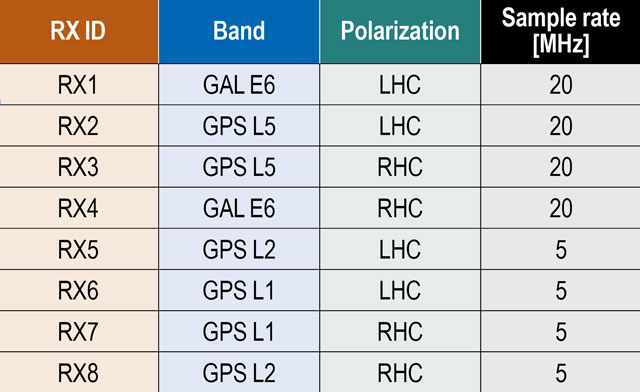
Each USRP can record up to four signals at two different mixdown frequencies, allowing for recording of both the RHC and LHC polarized signals on up to four different bands. The first USRP records the L1 and L2 bands with center frequencies at 1575.42 and 1227.6 MHz, respectively, at a bandwidth of 5 MHz. The second USRP records the L5 and E6/B3 bands at center frequencies of 1176.45 and 1271.25 MHz and at a 20 MHz bandwidth. TABLE 1 lists the IDs for each receive channel along with its corresponding band, polarization and sampling rate. Note that the recorded signals covering the E6 band also capture BeiDou B3 signals, but we restrict our analysis to GPS L1, L2 and L5 signals in this article. The samples from these USRPs are written to disk along with the Septentrio Binary Format (SBF) output of the PolaRxS receiver.
Table 1: Receiver IDs with corresponding band and polarization.
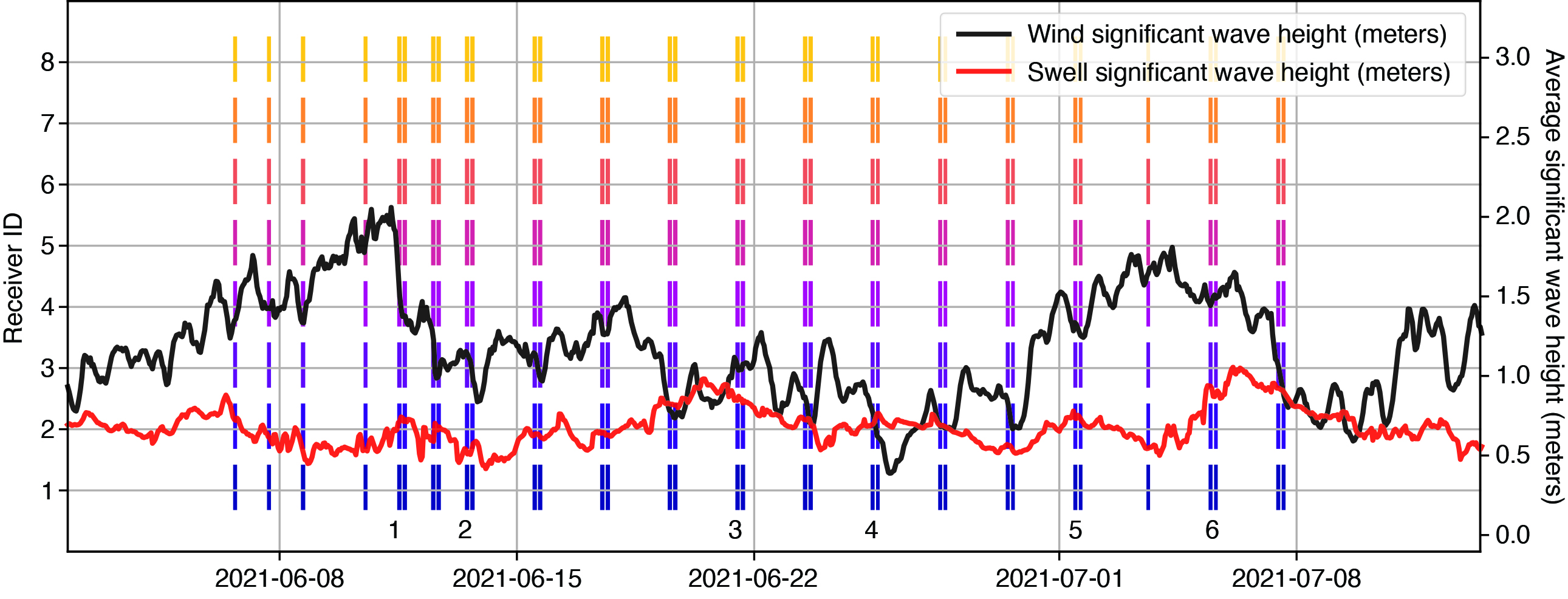
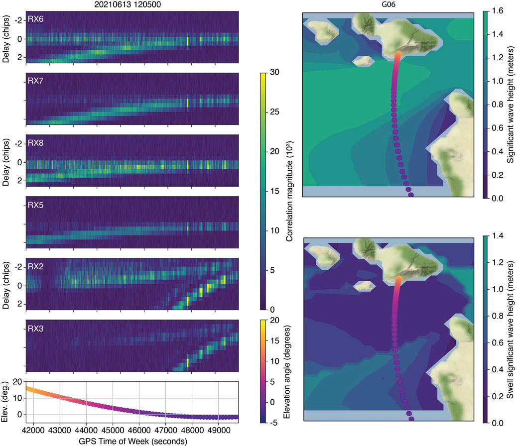
Starting in June 2021, periodic collections were taken for around one hour at a time, which is about the amount of time it takes for a GPS satellite to pass from an elevation angle of 0 degrees to one of more than 20 degrees. The collection times were adjusted to target the passes of satellites whose specular reflection point passed within the azimuthal range of the horn antenna, which faces roughly to the south and has a beam width of around 60 degrees. FIGURE 2 summarizes the available datasets from the first month of collections. The right-most panels of FIGURE 3 show examples of the specular track for GPS PRN 6 as it sets over the horizon on June 13, 2022, at around 12:00-13:00 UT. This is the pass on which we focus in this work, since PRN 6 transmits the L1CA, L2C and L5 signals and consistently had a specular point in our region of interest.
Figure 2: Available data during the first month of collections. The average significant wave height in the region south of Haleakalā is also plotted. Numbers near the bottom indicate the datasets analyzed for this article.
METHODOLOGY
Our processing method for open-loop tracking of the reflected GNSS signals is based on our previous work in which we produced DDMs and delay maps of the signal-to-noise ratio (SNR) measurements for multiple signal frequencies and received polarizations.
Pseudorange Model. We start by generating a model of the pseudorange for both the direct and reflected signal. The model only needs to be accurate down to the chip level, since we correlate across several chips of delay for the received signals. Setting a somewhat arbitrary accuracy requirement of 0.5 chips (equivalent to a delay of around 150 meters for L1CA/L2C or 15 meters for L5 signals), allows us to ignore path delays from the ionosphere and troposphere, which should only account for up to several meters of delay. The model has three terms that we estimate relative to GPS System Time (GPST): the receiver clock error, the satellite transmitter clock error and the geometric range. We use a surveyed position of the horn antenna along with International GNSS Service precise orbit and clock products for the transmitter clock error and positions. These allow us to compute the transmitter clock error and path delay for the direct signal. The reflected signal path delay can be found by computing the specular reflection point on the WGS84 ellipsoid and adding the distances from the transmitter to the specular point and the specular point to the receiver. The remaining term to estimate is the receiver clock error. Recall that our USRPs are driven by the Septentrio internal oscillator. Therefore, the clock error in Septentrio measurements is associated with variations in the reference oscillator for the USRPs. We utilize a geodetic detrending technique to estimate these clock variations and apply them to our pseudorange model. To construct the full receiver clock error, we estimate the time-alignment of the samples near the beginning of the collections to GPST by tracking one minute of a strong, mid-elevation-angle satellite and decoding its timing information. This provides us with an estimate of GPST at the start of the file, which we can use to construct a full estimate of the GPST at any sample in the file. Also, given our pseudorange model, we can find the received code phase and the Doppler frequency.
Figure 3: Example of delay maps from GPS PRN 6. The panels to the left show delay maps for the L1CA, L2C and L5 signals, both RHC and LHC polarizations. The bottom panel shows the corresponding elevation angle over the duration of the pass. The maps to the right show the specular point location during the pass, along with a contour of the WW3 model for significant wave height and swell-significant wave height.
Signal Correlation. Using the established code phase and Doppler models, we generate correlations for both reflected and direct signals. We correlate a reference signal over each 1-millisecond interval, and for sanity-checking purposes, we compute correlations over ± 3 chips at 0.5 chip spacing. This results in in-phase and quadrature (I/Q) correlation outputs every 1 millisecond. The left panels in Figure 3 show examples of the processed reflected signals for RHC and LHC polarization L1CA, L2C and L5Q signals from PRN 6 on June 13, 2021, at 12:00-13:00 UT. Note that as the satellite sets, at around 4 degrees elevation angle, the reflected signals merge with the stronger direct signal on the L1 and L2 signals. This happens later on L5 due to its higher bandwidth. We use the 0.0 chip bin to obtain I/Q outputs for carrier-phase processing for L1 and L2. For L5, we use the 0.0, -0.5, or -1.0 chip bin to account for model mismatch toward the end of the file.
Signal Fading and the WW3 Ocean Model. An eventual goal of the Haleakalā reflectometry experiment is to compare the characteristics of processed reflected signals with the ocean surface parameters near the specular point and glistening zone. To this end, we have incorporated data from the Hawaii regional WaveWatcher 3 (WW3) model. The model outputs information about wave height, direction and period due to both wind and swell, and has a resolution of around 5 kilometers. The data from this model is available in NetCDF format from several web services. The right panels of Figure 3 show contours of the wind- and swell-significant wave height in the South Haleakalā region. Meanwhile, note that the reflected signals (left panels) show high variability in the received power throughout the duration of the collection. While we hoped to be able to immediately observe a correlation between these wave parameters and the power fluctuations, it is clear that we need additional processing to tease out such a signal, and the changing satellite geometry will likely make this difficult to observe and validate. Even still, our results at the end of this article will show that there is likely some correlation between fading and wind parameters, though to what extent is unknown. Finally, note that the LHC polarizations (RX6, RX8, RX2) show much stronger reflected signals than the RHC polarizations. Since we are interested in processing the phase for the reflected signals, we report exclusively on the use of the LHC polarization signals in the rest of this article.
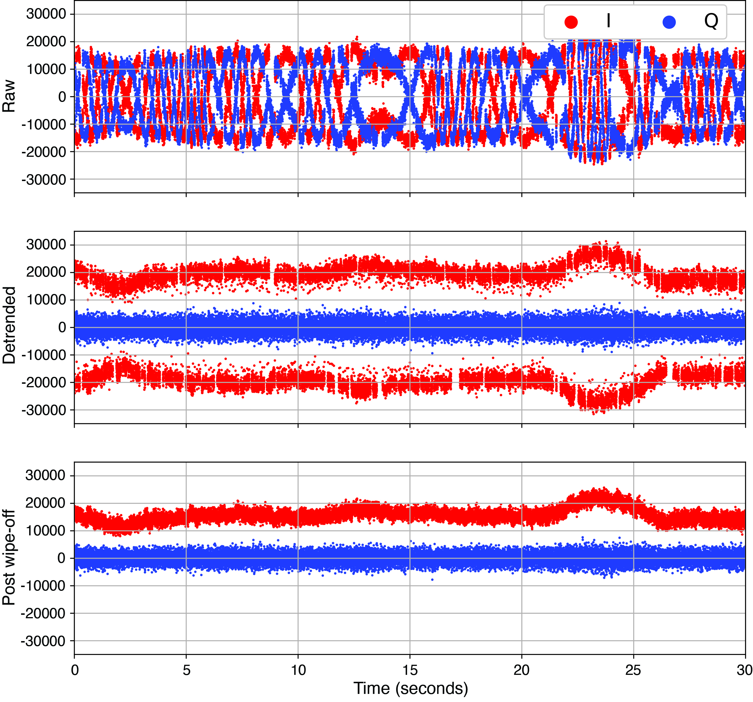
Carrier-Phase Processing. Once the correlations are performed, we take the I/Q correlations for both direct and reflected signals and process them to retrieve the cleaned reflected signal phase. The first series of steps in this process involve processing the direct signal to determine navigation / overlay symbol alignment and to estimate any residual phase fluctuations, which are mostly due to unmodeled receiver clock fluctuations. FIGURE 4 illustrates this process for the L1CA signal. The raw I/Q correlations are shown in the top panel. To these we apply a Costas phase-lock loop (PLL) to track the residual phase fluctuations without being sensitive to navigation / overlay symbol transitions. Next, we remove these residual phase fluctuations to obtain the detrended I/Q values.
Figure 4: The I/Q data cleaning process for the L1CA direct signal.
As shown in the second panel, these quadrature components of the detrended I/Q values are centered at zero while the in-phase component now shows the data bits / overlay symbols. We use the detrended I/Q values to estimate the navigation bit sequence on the L1CA and L2C signals. Likewise, we estimate the alignment of the Neumann-Hoffmann overlay sequence for the L5 signal. Finally, we wipe off the estimated data bits or overlay sequence to verify the procedure. The results of wiping off the estimated navigation bits for the L1CA signal are shown in the third panel of Figure 4.
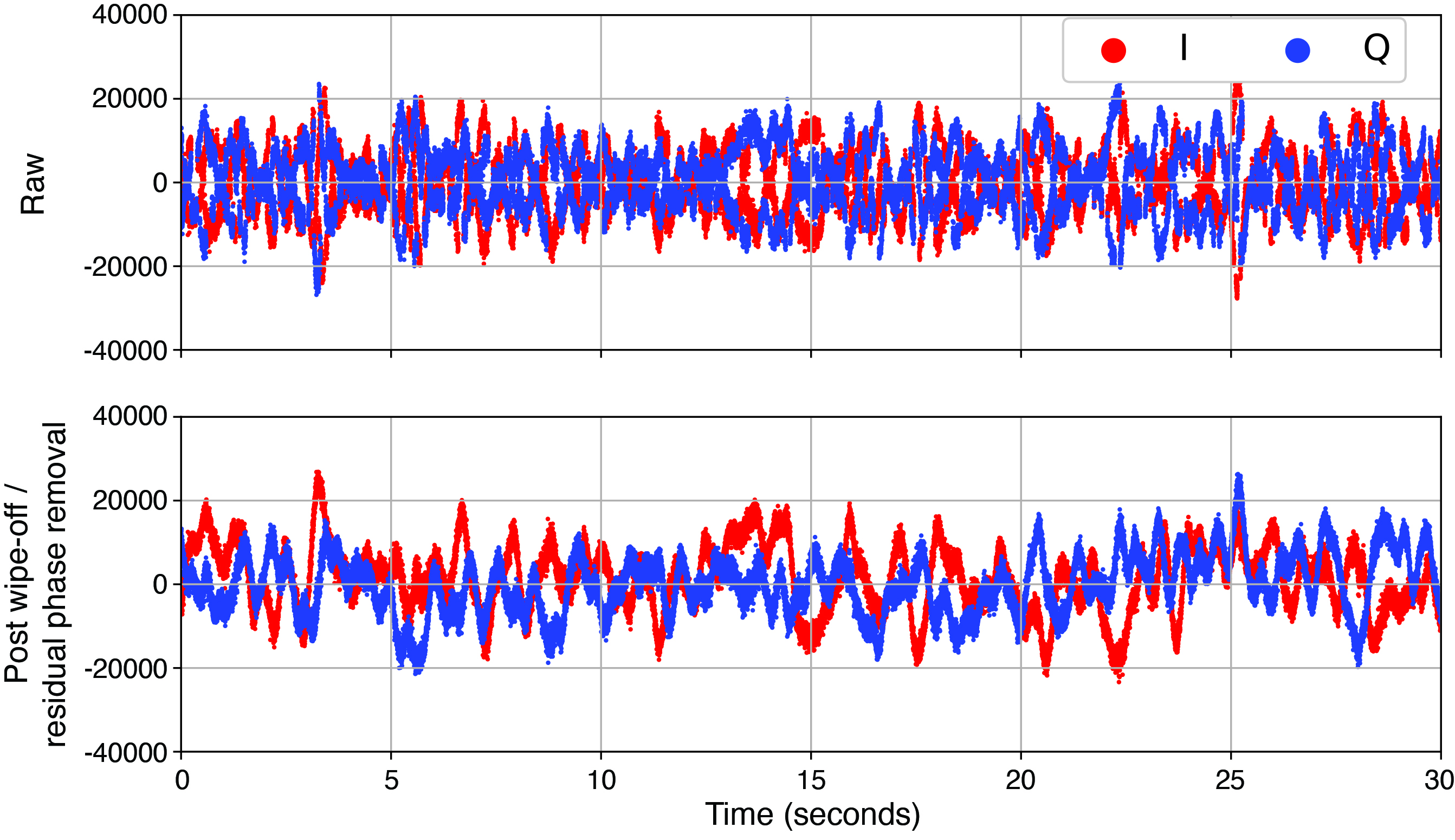
Having obtained the residual phase fluctuations and navigation / overlay symbols for the direct signal, we next apply these to clean up the reflected signal. Specifically, we remove residual phase fluctuations from the raw reflected signal I/Q values and then wipe off the corresponding navigation bits or overlay code. FIGURE 5 shows an example of the reflected I/Q data before and after this procedure. The navigation bits are clearly removed, but the reflected signal still shows fairly significant fluctuations in the cleaned I/Q values. It is from these values that we hope to extract the residual reflected signal phase.
Figure 5: The reflected signal raw I/Q (top) and the I/Q after detrending and wiping off navigation bits for the L1CA signal.
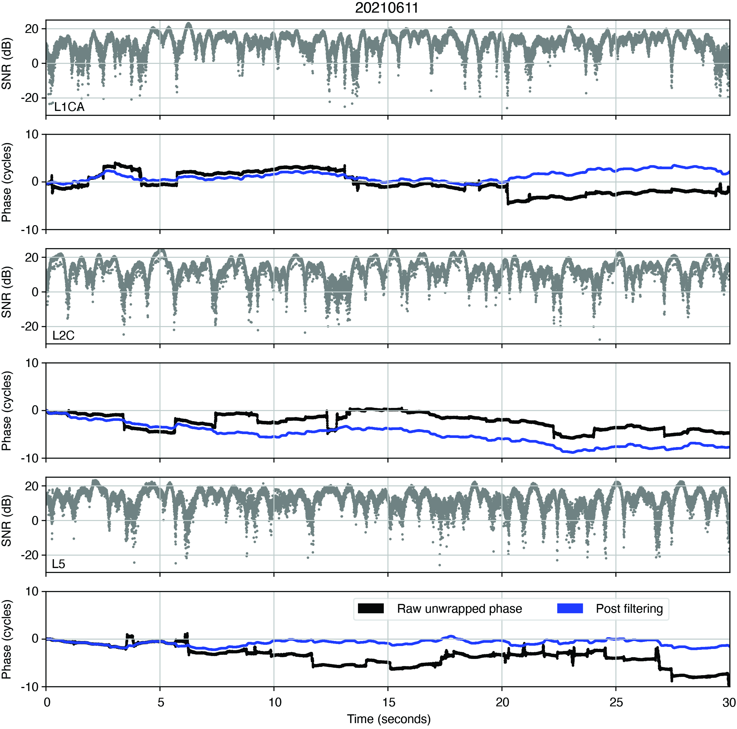
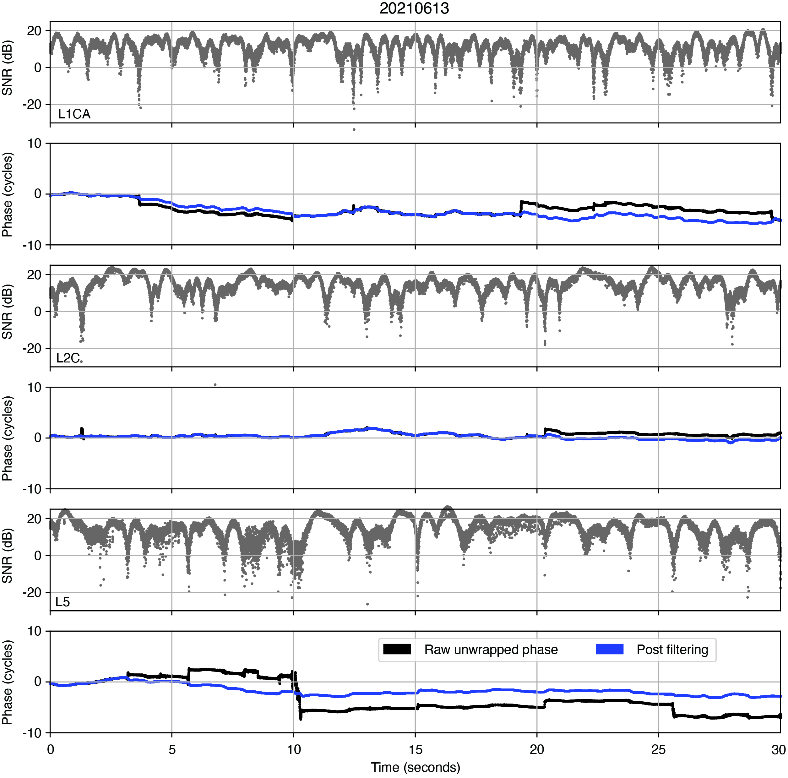
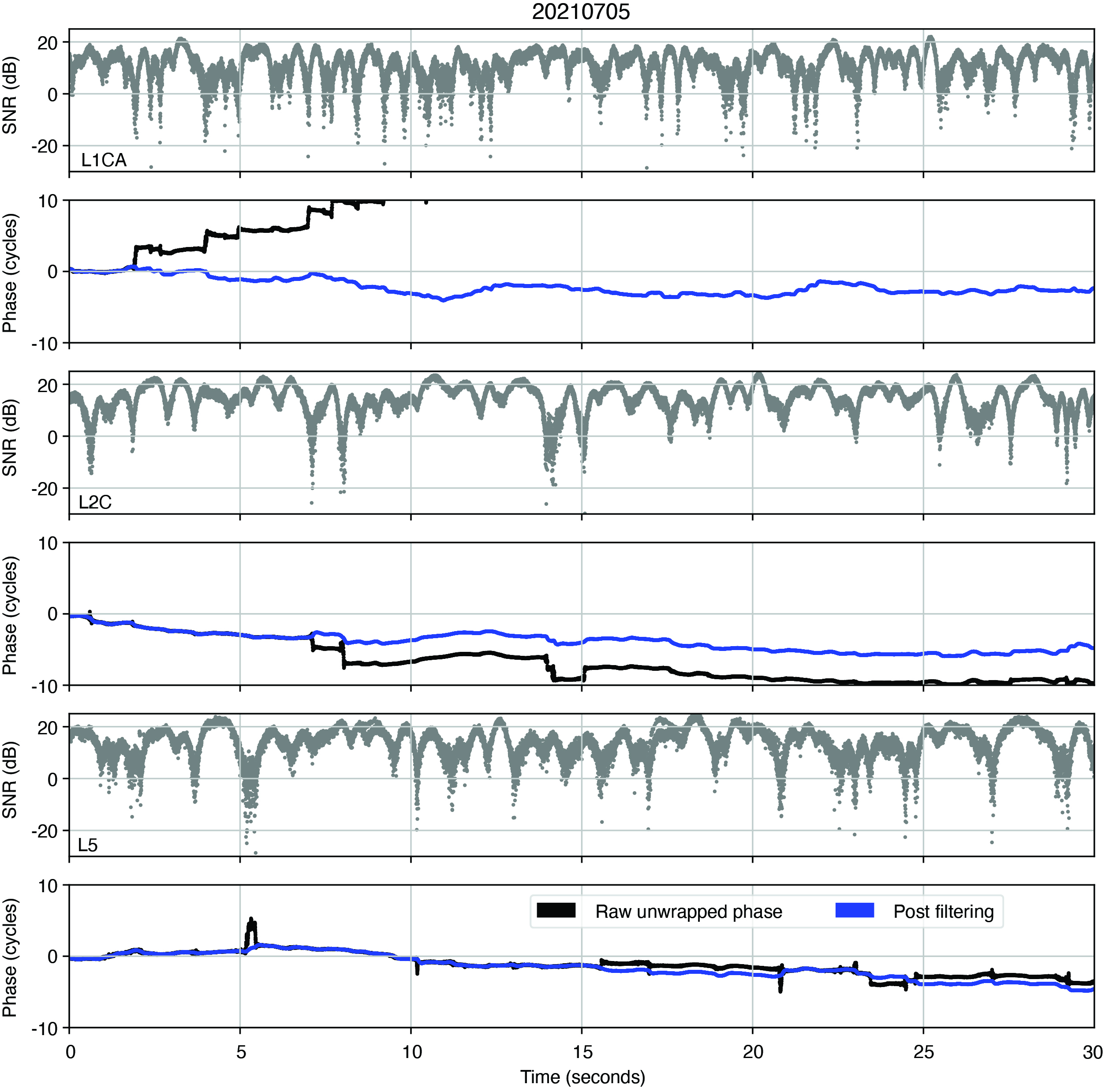
Under coherent conditions, the phase of the clean reflected I/Q data should contain only the unmodeled effects, including any signature of ocean surface height variation. However, the effect of multipath due to the rough ocean surface causes fluctuations in the received signal amplitude and phase, and can additionally cause cycle slips when we unwrap the phase. To filter out these cycle slips, we apply our simultaneous cycle slip and noise filtering (SCANF) method, which is essentially just a Kalman filter PLL with an additional step that tries to estimate and remove cycle slips. The figures in the next section show the results of applying this entire procedure to the reflected signals. The black and blue lines show the phase before and after applying SCANF. The reflected signal I/Q SNR is also included for reference. Note how the jumps in the black line coincide with SNR fades, and the blue line effectively recreates the phase trend of the black line without these jumps. This is good qualitative evidence that the SCANF algorithm was effective.
RESULTS
FIGURES 6, 7, 8, 9, 10, and 11 show the reflected signal SNR and phase for GPS PRN 6 on 6 different days. Note that these days correspond to the marked days in Figure 2, from which we observe that the wind-significant wave height is relatively high on days 1, 5, and 6, moderate on days 2 and 3, and relatively low on day 4. We noticed that the SNR fluctuations on days 1, 5, and 6 are comparatively more frequent than on other days, which we believe may be a signature of the ocean surface conditions. A more detailed analysis of this result is a topic for our future work.
Figure 6: Reflected signal residual phase before (blue) and after (black) applying the SCANF filtering for the June 11, 2021 dataset. Amplitude and phase are shown in alternating panels for L1CA, L2C and L5 respectively.Figure 7: Phase processing results for June 13, 2021.
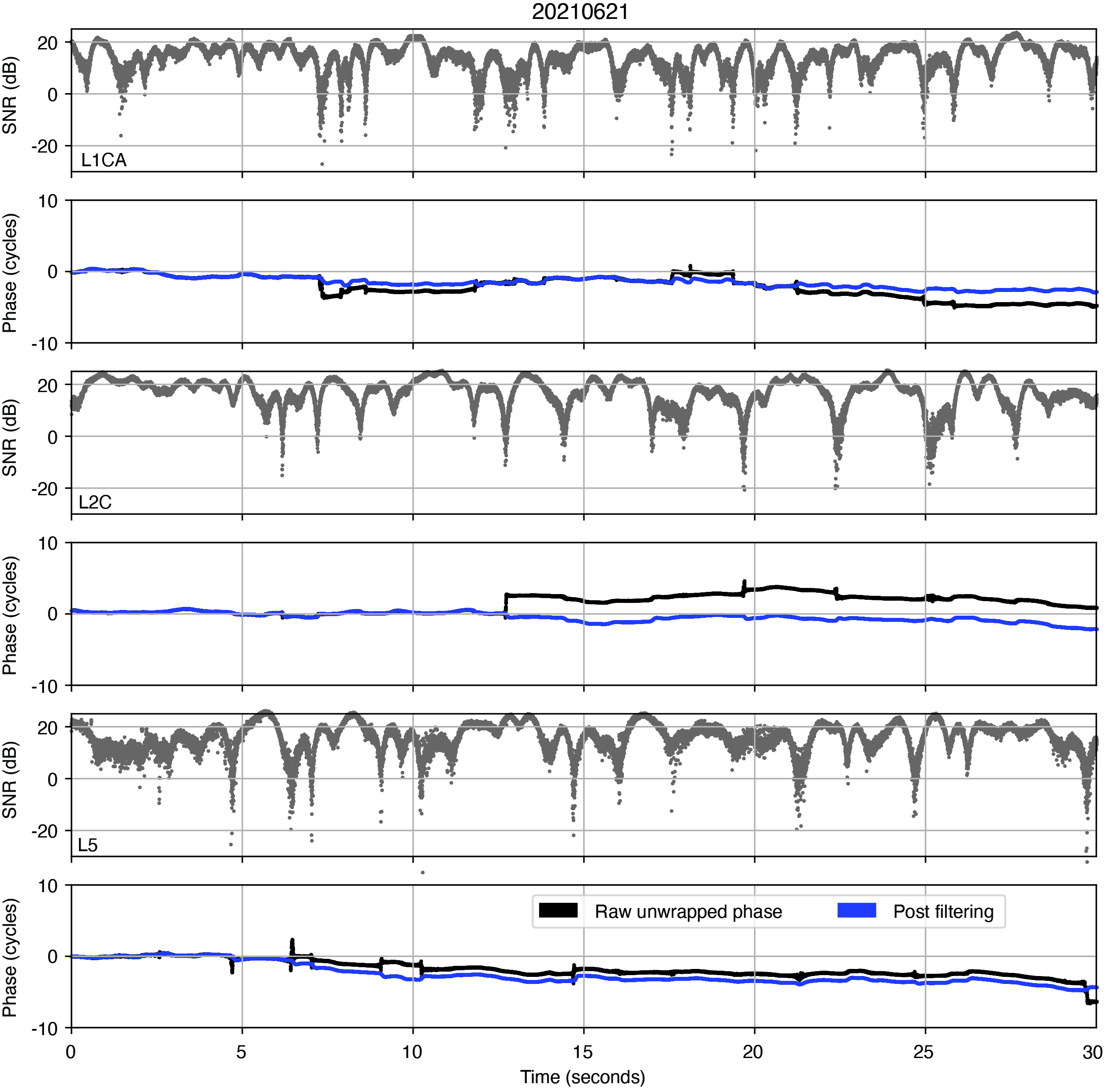
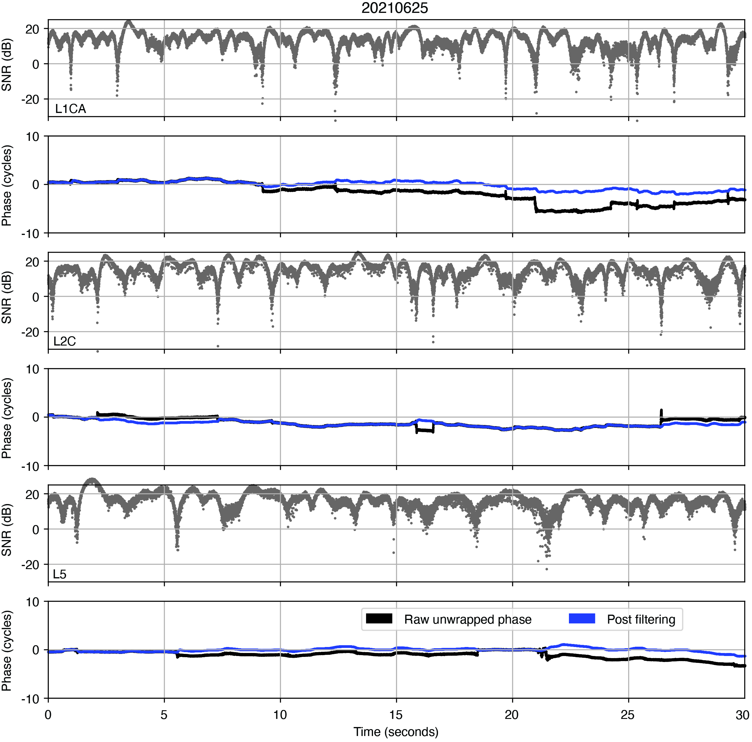
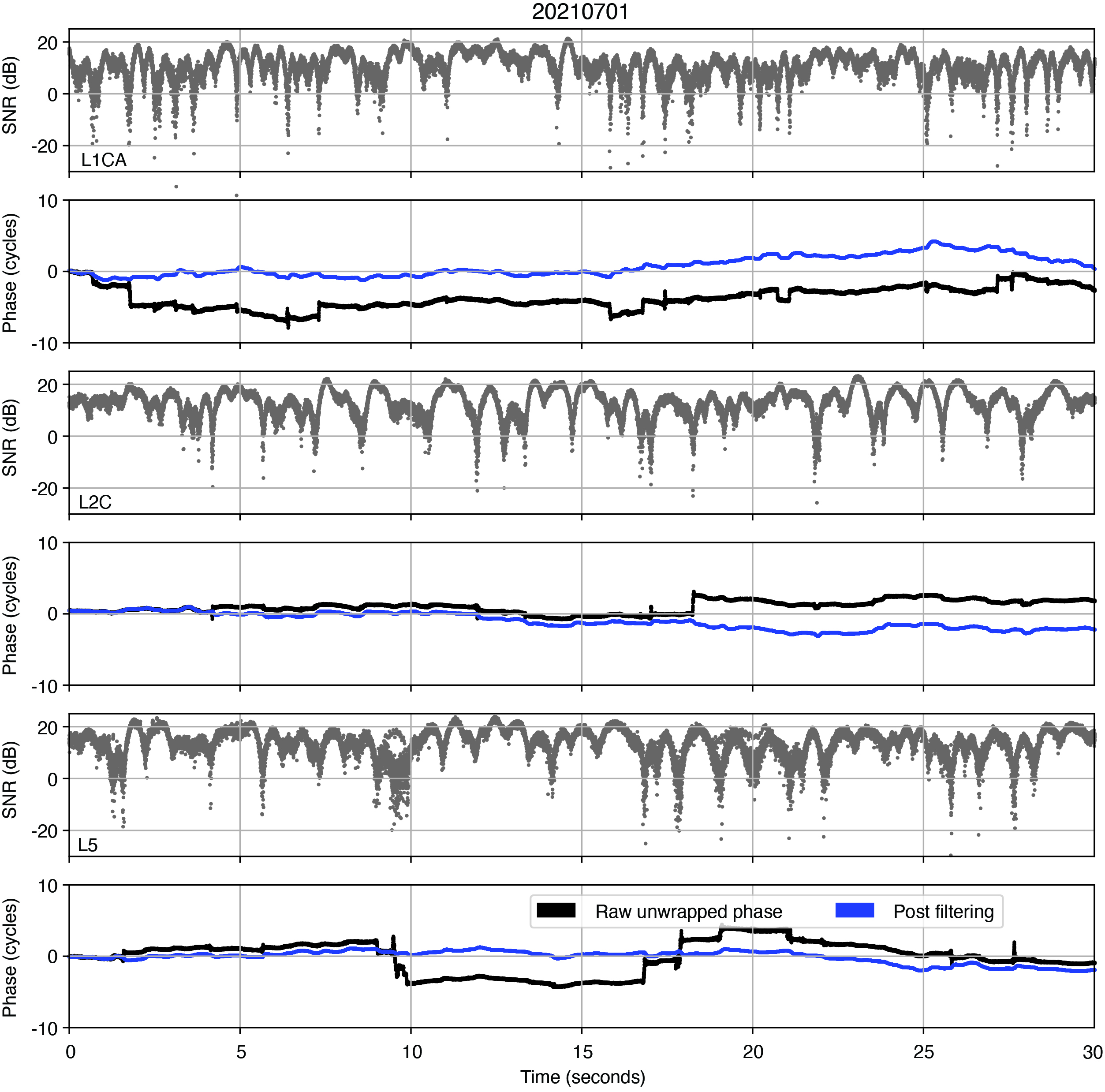
Overall, we observe that the phase trend is not consistent across the three signals (L1CA, L2C, L5) for any of the days. With all the multipath signatures in the cleaned reflected signal, it was uncertain whether the extracted phase will be useful for applications such as ocean surface altimetry, and these qualitative results suggest that they probably will not be. However, season and hours of the day that were processed for our work discussed in this article are very limited. It is possible that processing more data will shed further insight onto whether the reflected signal phase is usable in this experiment.
Figure 8 Phase processing results for June 21, 2021.Figure 9: Phase processing results for June 25, 2021.
ACKNOWLEDGMENTS
The Haleakalā data collection system has been established with support from the University of Hawaii Institute of Astronomy, and the Air Force Research Laboratory. The authors appreciate the assistance from Michael Maberry, Rob Ratkowski, Daniel O’Gara, Craig Foreman, Frank van Graas and Neeraj Pujara. This research is funded by a subaward from the National Oceanic and Atmospheric Administration through the University Corporation for Atmospheric Research to CU Boulder and with partial funding support from the NASA Commercial Smallsat Data Acquisition program.
This article is based on the paper “Initial Carrier Phase Processing for the Haleakala Mountaintop GNSS-R Experiment” presented at ION ITM 2023, the 2023 International Technical Meeting of the Institute of Navigation, Long Beach, California, Jan. 23–26, 2023.
Figure 10: Phase processing results for July 1, 2021.Figure 11: Phase processing results for July 5, 2021.
BRIAN BREITSCH is a postdoctoral fellow at the University of Colorado (CU) Boulder, where he received his Ph.D. in aerospace engineering sciences. JADE MORTON is a professor in the Ann and H.J. Smead Department of Aerospace Engineering Sciences and the director of the Colorado Center for Astrodynamics Research at CU Boulder.
A roundup of recent products in the GNSS and inertial positioning industry from the November 2023 issue of GPS World magazine.
SURVEYING & MAPPING
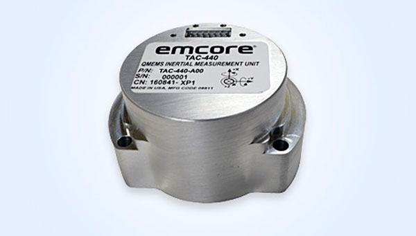
MEMS IMU Suitable for rugged environments
The TAC-440 MEMS inertial measurement unit (IMU) is designed for demanding, mission-critical, rugged environments in a wide variety of defense, commercial, industrial, and marine applications. The TAC-440 features 1°/hr gyro bias and 1 mg accelerometer bias stability with 0.05°/√hr angle random walk over a wide temperature range. The solid-state quartz sensors and hermetically sealed IMU construction provide reliable MTBF and storage life, EMCORE stated. The TAC-440 supports four data message synchronization methods with either input synchronization pulse capability or an output time of validity capability. The user can choose whether the synchronization pulse is internally generated and output as a time of validity of the output data or whether the TAC-440 software will identify the synchronization pulse input and synchronize the output data to the input pulse. EMCORE Corporation, emcore.com
RTK GNSS Tablet A rugged device designed for geospatial and mapping operations in the field
The LT800H offers users robust outdoor performance, data security and centimeter-level accuracy for a variety of applications, including construction, environmental surveying and any industry in which Android tablets are used. Featuring a high-performance 1,408-channel GPS, GLONASS, Galileo and BeiDou module and a tracking GNSS helix antenna, the LT800H RTK Android tablet offers centimeter-to-decimeter positioning accuracy in challenging environments. It also comes equipped with a 4G modem to simplify connectivity to GNSS RTK network corrections. The technology also offers an eight-hour battery life, allowing users to collect data in the field uninterrupted. CHC Navigation, chcnav.com
PPK Software For land surveying, hydrography, airborne surveys, construction, and applications that require precise positioning
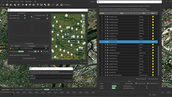
The Qinertia 4 contains an enhanced geodesy engine that has an extensive selection of preconfigured coordinate reference systems (CRS) and transformations, making it a suitable solution for applications that use diverse geodetic data. To tackle the challenges of variable ionospheric activity, Qinertia 4 features an Ionoshield post-processed kinematic (PPK) mode. This feature compensates for ionospheric conditions and baseline distances, enabling users to perform PPK even for long baselines and/or harsh ionospheric conditions. This ensures surveyors can achieve centimeter accuracy even in regions with unpredictable ionospheric disturbances. Another addition to the Qinertia 4 is an extended network support for continuously operating reference stations (CORS). This feature gives users access to a network of 5,000 SmartNet CORS for reliable GNSS data processing. These base stations add to the network of base stations directly available in Qinertia, bringing the total to more than 10,000 bases in 164 countries.
For data that cannot be processed using PPK, Qinertia 4 offers an alternative solution with its tightly coupled precise point positioning algorithm. This new processing mode, available for all users with active Qinertia maintenance, provides post-processing anywhere in the world without a base station, with a horizontal accuracy of 4 cm and a vertical accuracy of 8 cm. SBG Systems, sbg-systems.com
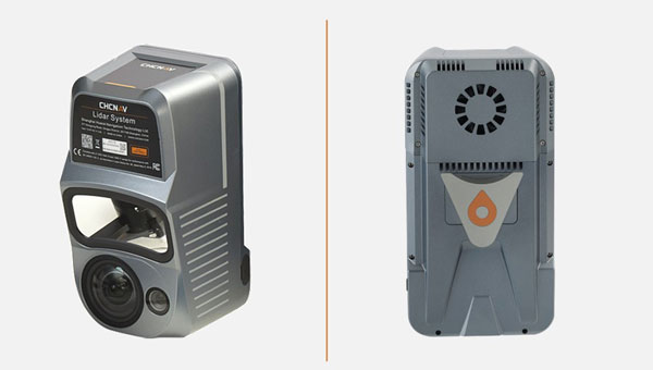
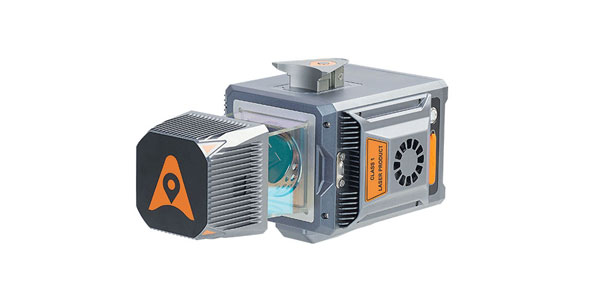
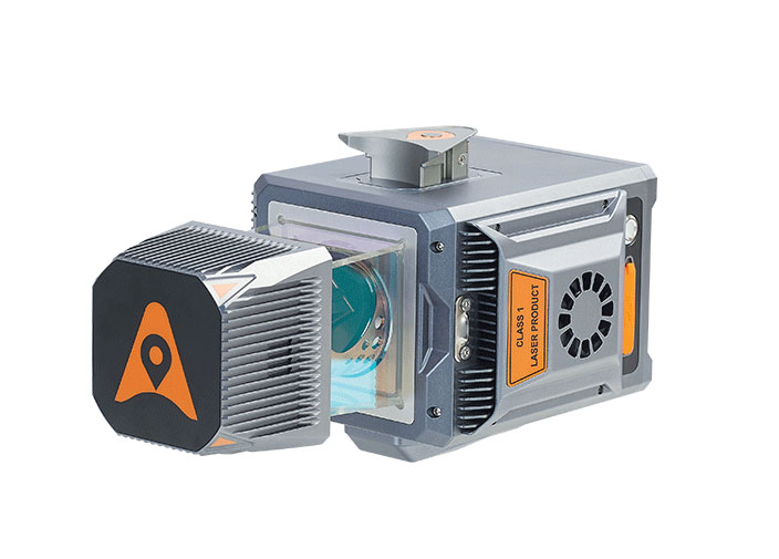
Airborne Lidar + RGB System Designed to enhance the details of aerial mapping operations
The AlphaAir 10 (AA10) features a high-precision navigation algorithm that provides 5 mm repeated range accuracy and achieves absolute precision in the 2 cm to 5 cm range, even in complex environments. The AA10 is capable of long-range measurements of up to 800 m, rapid scanning at 500,000 points per second, and features a continuously rotating mirror that enables scanning speeds of 250 scans per second. The AA10 enables the creation of mesh models by generating high-quality point clouds. It is powered by a 45 MP orthographic internal camera that provides high-resolution image mapping textures for 3D model reconstruction with realistic point cloud colorization. The AA10 also supports automated reality capture and real-time data visualization accessible directly from the UAV controller. The AA10 lidar system is lightweight and compact, weighing 1.55 kg, and provides a 30 min operating time when integrated with UAVs such as the DJI M350. The system is also IP64-rated. CHC Navigation, chcnav.com
GNSS Receiver Designed for survey projects
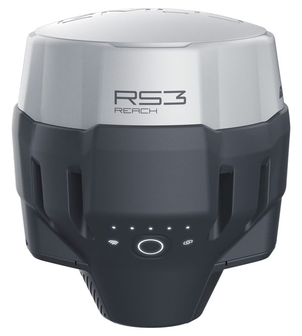
The Reach RS3 is a GNSS receiver that features inertial measurement unit (IMU) tilt compensation and a dual-band radio for enhanced compatibility with third-party receivers. The Reach RS3 enables users to survey at large tilt angles while maintaining survey-grade accuracy. The multi-band receiver works both as a base and a rover and comes factory calibrated. The receiver offers versatile options to get corrections from continuously operating reference stations (CORS), another Reach device, or a third-party base, so users can mix and match real-time-kinematic (RTK) receivers in a fleet. Its NTRIP connectivity enables corrections from CORS, NTRIP service, or a GNSS receiver using Emlid NTRIP Caster. When connected over NTRIP, Reach works on a baseline of more than 60 km in RTK and 100 km in post-processed kinematic. Emlid, emlid.com
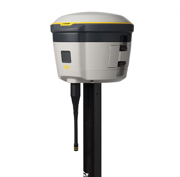
GNSS Receiver Includes Trimble ProPoint and delivers survey precision and productivity in the field
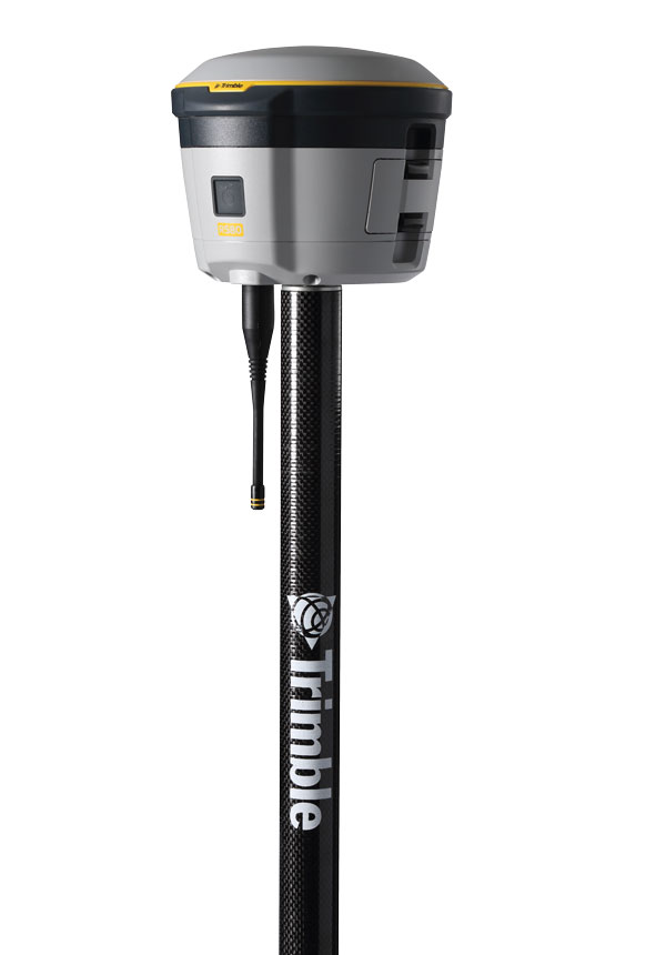
The R580 GNSS receiver enables professionals in surveying, mapping and GIS, civil construction, and utilities to capture centimeter-level positioning. With the Trimble ProPoint GNSS engine embedded, users can measure points in challenging environments, such as under tree canopy or near buildings, while EVEREST Plus technology can identify and remove unwanted multipath signals for improved accuracy and data confidence. Using the Maxwell 7 chipset technology, the receiver provides fast processing, anti-spoofing capability and the ability to track all available GNSS constellations. The R580 supports Trimble RTX correction services for RTK-level precision without the use of a local base station or VRS network wherever correction sources are available. The receiver can be paired with all current mobile devices on a variety of operating systems and platforms —from a Trimble handheld or controller to a modern smartphone or tablet. It can also be mounted on a pole, vehicle or backpack. Trimble, trimble.com
OEM
GNSS Module Supports L1/L5 GNSS bands from multiple constellations, including NavIC
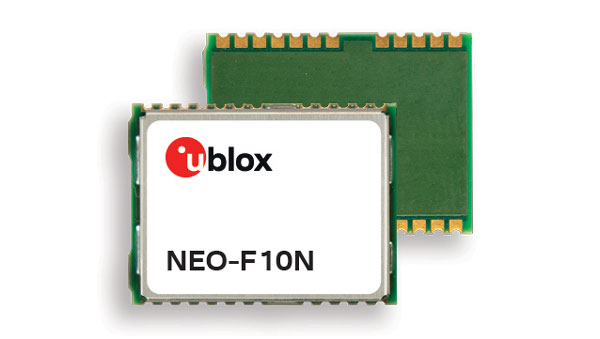
The NEO-F10N positioning module is based on the u-blox NEO form factor and is equipped with u-blox F10 dual-band GNSS technology. The NEO-F10N supports L1/L5 GNSS bands from multiple constellations — including NavIC — to provide meter-level position accuracy in urban areas. Its firmware is upgradeable and configurable to support several applications such as the vehicle telematics and micromobility markets or industrial applications requiring meter-level position accuracy. The NEO-F10N improves position accuracy in urban environments with its enhanced resilience against multipath interference. By leveraging signals from both the L1 and L5 bands, this module achieves better accuracy than using the L1 band alone. Users currently employing receivers based on modules such as the u-blox NEO-M8 and NEO-M9, can migrate to the new NEO-F10N generation. The module enhances accuracy, reduces power consumption, and offers an alternative solution to users who do not want to deploy dead reckoning set-ups. u-blox,u-blox.com
Multi-Band GNSS Antenna Designed to enhance meter-level positioning solutions
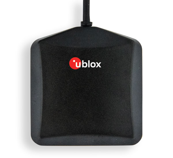
The ANN-MB5 is a multi-band (L1/L5/E5a/B2a) GNSS antenna that is optimized for the u-blox F10 platform and enables precise, reliable, and robust positioning, even in challenging environments. The antenna features concurrent reception of multiple navigation systems, including NavIC. The ANN-MB5 has a compact design with a magnetic base. u-blox, u-blox.com
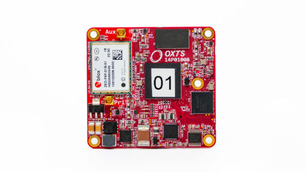
INS A product for mobile mapping, autonomy, and more
The xRED3000 inertial navigation system (INS) offers quad-constellation GNSS support for multiple applications. The INS weighs 20 g, making it suitable for aerial payloads. At 53.6 mm x 50.6 mm x 9.5 mm in size, it can be incorporated without drastically changing a user’s design. When in a GNSS-denied area, the xRED3000 provides a position accuracy of 0.5 m even after 60 seconds. It features gx/ix tight-coupling algorithms, which improve accuracy in urban canyons and speed up real-time kinematic reacquisition after temporary GNSS outages. The xRED3000 features lidar inertial odometry, which takes data from lidar in post-processing to reduce inertial measurement unit drift and improve accuracy in areas with poor or no GNSS signal. Additionally, embedded NTRIP makes it easier to get GNSS corrections. OxTS, oxts.com
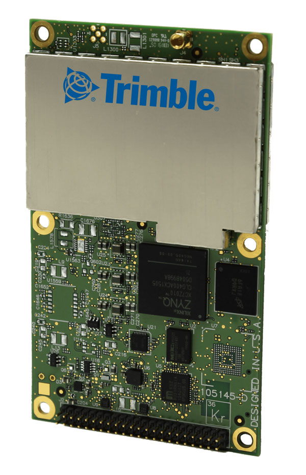
Triple Frequency GNSS Receiver Complete with a compact design for mobile applications
The BD990 supports triple frequency for the GPS, GLONASS, BeiDou and Galileo constellations. The receiver offers quick and reliable real-time kinematic (RTK) initializations for centimeter positioning. It features Trimble Maxwell 7 technology, which provides 336 tracking channels, Trimble Everest Plus multipath mitigation, and advanced RF spectrum monitoring and analysis. With the option of utilizing OmniSTAR or RTX services, the BD990 delivers varying levels of performance down to centimeter-level without the use of a base station. The BD992 also supports dual antenna GNSS heading while the BD992-INS supports position and orientation at high update rates. Trimble, oemgnss.trimble.com
MACHINE CONTROL
Automated Steering System Designed for precision agriculture applications
The SAgro150 automated steering system aims to provide farmers with an easy way to get started with auto-steering. With full-constellation tracking capability, the SAgro150 realizes ±2.5 cm auto-steering accuracy to maximize land use and yield while saving resources such as water and fertilizer. When compared to the first-generation SAgro100 system, the SAgro150 auto-steering system uses a single-antenna solution instead of a dual-antenna solution. It also features simpler integration options, only requiring a strong magnetic chuck to securely attach the antenna to the top of the tractor for satellite signal tracking. The new system also adopts dual gyroscope mode, enhancing the heading data reliability and compatibility with different tractors. The new system aids in applications such as rotary tillage, ridging, sowing and harvesting in straight line, curve, U-turn and more. SingularXYZ, singularxyz.com
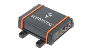
Positioning and Heading Receiver Designed for multiple applications
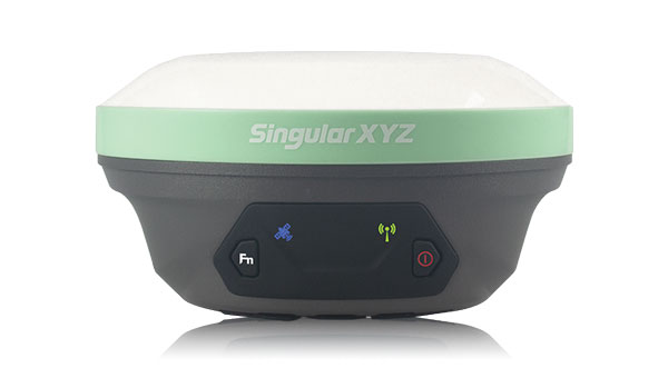
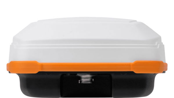
AsteRx SB3 Pro+ is a housed multi-frequency GNSS receiver that uses triple-band GNSS technology for reliable centimeter-level real-time kinematic (RTK) positioning and sub-degree heading. With flexibility to be used as a rover or a base station, AsteRx SB3 Pro+ also has an ultra-high update rate and logging functionality. Enclosed in a ruggedized IP68 housing, the device is suitable for harsh environments. The AsteRx SB3 Pro+ has a high update rate and low latency for fast moving vehicles or machine parts. Septentrio, septentrio.com
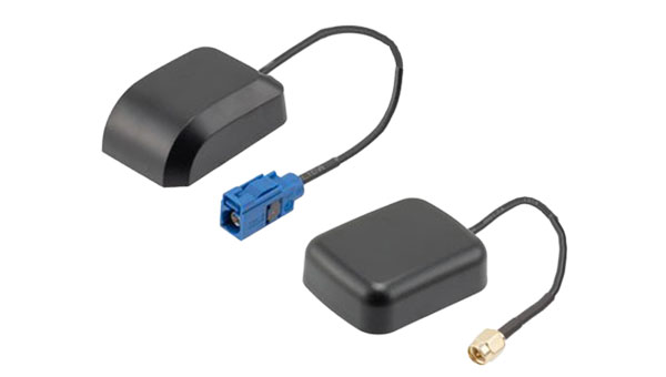
GPS Antennas Offers enhanced navigation and tracking for automotive applications
The KP Performance vehicle GPS antennas come equipped with a gain of 28 dB to capture weak signals, even in the most challenging environments. The antennas also feature high out-of-band rejection. By minimizing signal interference and multipath effects, the antennas provide good signal quality and stability. The features of the antennas enable more precise navigation and enhanced user experiences for personal vehicles, commercial fleets, or autonomous systems. The antennas have a IPX6- or IP66-rated waterproof and dustproof design for reliable operation in harsh conditions. KP Performance, kpperformance.com
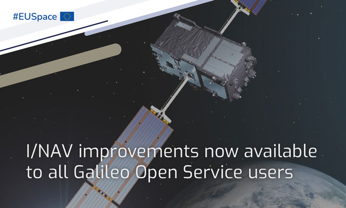
I/NAV improvements for all Galileo Open Service users is a part of the new Galileo services portfolio. (Image: EUSPA)
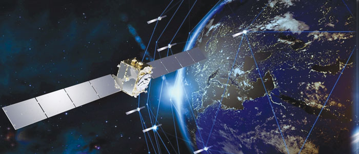
In 2023, Galileo continues to provide the world’s most precise satellite navigation information, to more than four billion users worldwide. Galileo services have expanded with many new capabilities that are unique with respect to other GNSS.
EUSPA and ESA continue to enjoy an effective collaboration on the many development, deployment and evolution activities of the Galileo Program, each according to its responsibilities for service provision and system development with the European Commission acting as the program manager.
Stable service performance
The service delivery operations, and the maintenance of the operational systems, are managed by EUSPA, who supervises several contracts that carry-out the day-to-day activities from dedicated control and monitoring centers throughout Europe. The Galileo timing, navigation and SAR/Galileo services provided in 2023 have been delivered with excellent performances that continue to exceed the formal declarations for minimum performance levels (MPL), both in terms of absolute accuracy and overall service availability.
Expansion of service portfolio
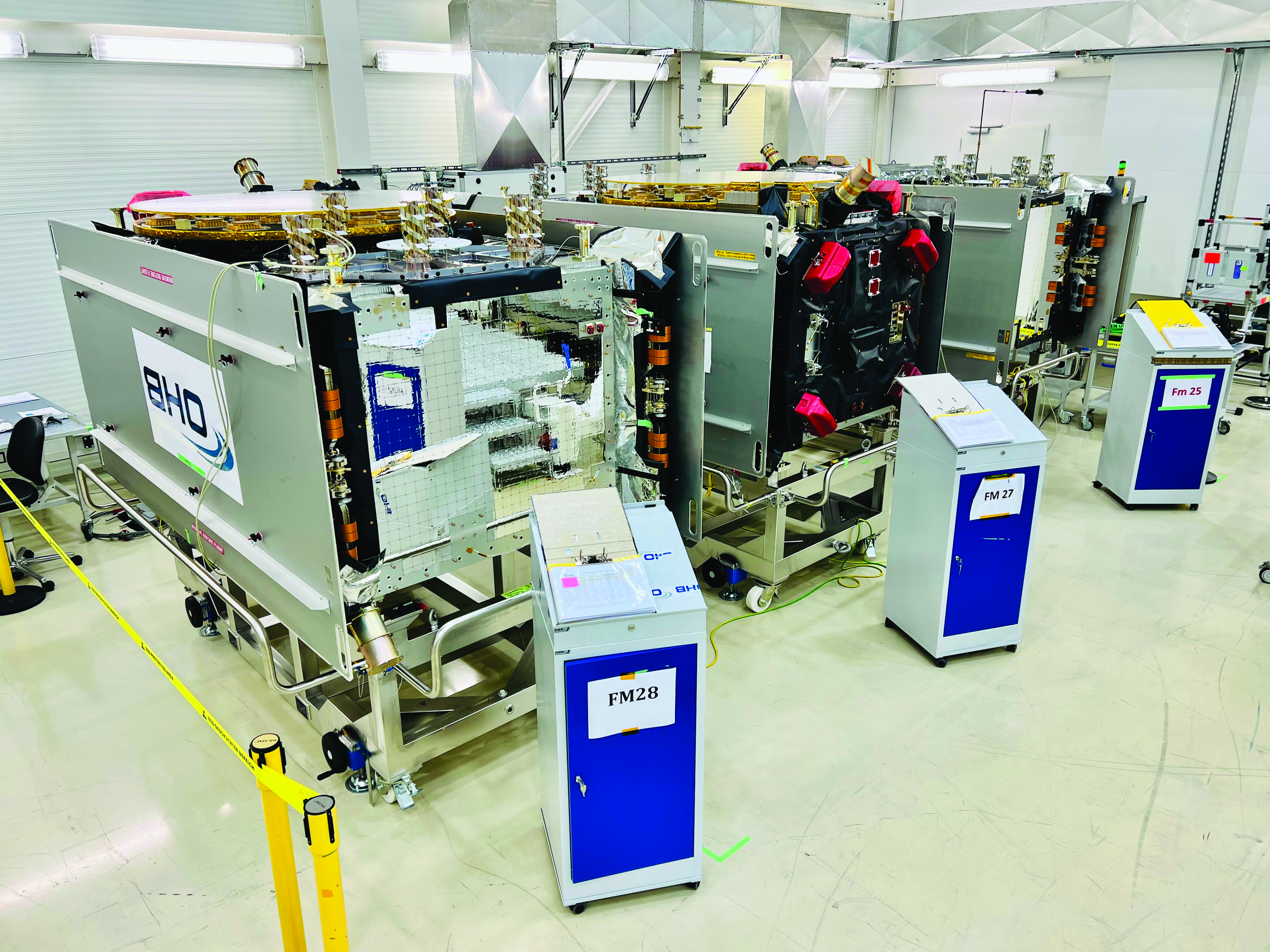
Galileo FOC batch three satellites in storage at OHB Systems. (Image: ESA)
The service provision teams have been able to focus on improvements to, and expansion of, the Galileo service portfolio.
OS and I/NAV improvement
Galileo Open Service (OS) users can already benefit from an improved navigation message, being broadcast by the Galileo constellation since mid-2023, which considerably boosts their performance in terms of robustness and time to first fix.
An update of the Galileo OS service definition document (SDD) is planned for the end of this year. This fourth issue of the OS SDD will bring to the users new MPLs (e.g., ranging rate accuracy and ranging accuracy at high percentiles) and improvements of existing MPLs, such as the timeliness of certain notice advisories to Galileo users. This updated OS SDD will also introduce the OS extended operation mode, which is characterized by a gradually degrading ranging accuracy with respect to the nominal operational mode, including outages of the Galileo ground segment, thus increasing the robustness of the OS.
High Accuracy Service
As of the HAS initial service declaration on January 24, Galileo became the first GNSS constellation ever to enable a decimetre-level accuracy, free of charge on a 24/7 basis over most parts of the globe in nominal conditions. The HAS corrections are transmitted directly via the Galileo signal in space (E6-B) and through the internet with the corresponding performance levels systematically met since the declaration. All documentation available here.
OS-NMA
The OS Navigation Message Authentication (OSNMA) will be a free and open access service allowing the users to confirm that received Galileo navigation data has not been modified and originates from the Galileo system, thus increasing the likelihood of detecting spoofing attacks at the data level and significantly contributing to the security of the solution. The OSNMA public observation phase is currently ongoing (gsc-europa.eu/support-to-developers/osnma-public-observation-test-phase). As part of that, the final OSNMA signal in space (SiS) interface control document (ICD) was published in December 2022, while the broadcast of a compliant SiS together with test certificates for the public key infrastructure started in August, marking the start of the OSNMA initial operational capability. The OSNMA initial service declaration will be achieved after the completion of the service validation activities and is targeted for early 2024.
Safety of life
The Galileo contribution to safety of life services (GoSoL) will cover the provision of Galileo signals and of service guarantees to enable the implementation of horizontal ARAIM service supporting aviation users. The service roadmap is currently under definition with a stepwise approach that will include the broadcast of a test ISM before the operational service is provided.
SAR
SAR/Galileo provides accurate, timely, and reliable distress alert data to help rescue authorities assist in distress situations (forward link service). It also acknowledges the receipt of the distress forward link alert to the beacon in distress via the Galileo navigation SiS (return link service). SAR/Galileo is a geographically distributed system, which was extended with a fourth European MEOLUT installed in La Reunion, in operation since November 2022.
The combination of SAR/Galileo space and ground assets provides excellent performance levels with a mean location accuracy of less than 800 m and a return link delivery latency of less than 1 min, which assisted in the rescue of approximately 1,400 people within EU territories in 2022.
Utilizing the return link service capabilities brings new innovations that further contribute to the global emergency space operations as Galileo moves forward to the implementation phase of the emergency warning satellite service (EWSS). The EWSS will provide national civil protection authorities with a satellite broadcasting capability to broadcast on-demand authenticated alerts to a precise target area and its population directly to any device capable of processing Galileo signals.
Reference documents for each of the above services can be found at the EUSPA European GNSS Service Center website, including technical notes, interface control documents and service declaration documents.
Image: European Space Agency (ESA)
Full operational capability infrastructure development toward completion
Space segment
The production of the third batch of Galileo FOC satellites, by the satellite manufacturer OHB Systems, has been completed for an overall amount of 12 satellites. The acceptance review for the last couple of spacecraft took place in June.
This amounts to an overall production by OHB Systems of 34 Galileo FOC Satellites (14 satellites in batch one, eight satellites in batch two and 12 satellites in batch three) of which 24 are in orbit. The remaining 10 satellites are in storage waiting for the next launch opportunity in 2024.
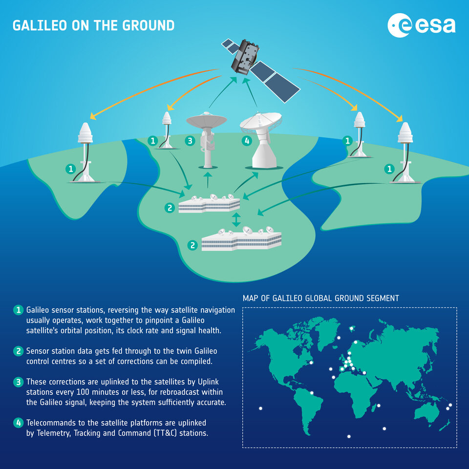
Ground segment
G2SB1 engineering model payload testing at ESA ESTEC. (Image: ESA)
The ground segment is going through a major upgrade with the roll-out of the new System Build 2.0 infrastructure in support of public regulated service IOC and open service FOC.
The new version of the ground mission segment developed by Thales Alenia Space France will be oriented to increase service robustness and resilience, besides high performance. It will provide virtualized hardware and software infrastructure at the Galileo Control Centers, triple receiver chain redundancy in the sensor stations’ remote sites and two additional sites located in Wallis (Pacific Ocean) and Bonaire (Caribbean Sea) to increase global coverage with 15 sites overall. A new mission monitoring capability has been implemented for the operators using the SAFE/Agile methodology. Furthermore, a system extended contingency mode will be implemented to cope with outages lasting up to seven days with smooth navigation performance degradation.
A new version of the Galileo Security Facility will be deployed at the Galileo Security Monitoring Centers offering an evolution of the public regulated service (PRS) capabilities through new enhanced SiS access control. Furthermore, a new state of the art cyber security monitoring system will be implemented.
The System Build 2.0 infrastructure qualification was completed by ESA in July. Migration in operation is based on an innovative concept consisting of a replica of the operational chains to ensure seamless transition from the current system in operation to the newly deployed one. The completion of the migration into operations is planned for the beginning of 2024, with the schedule being continuously monitored at the program level.
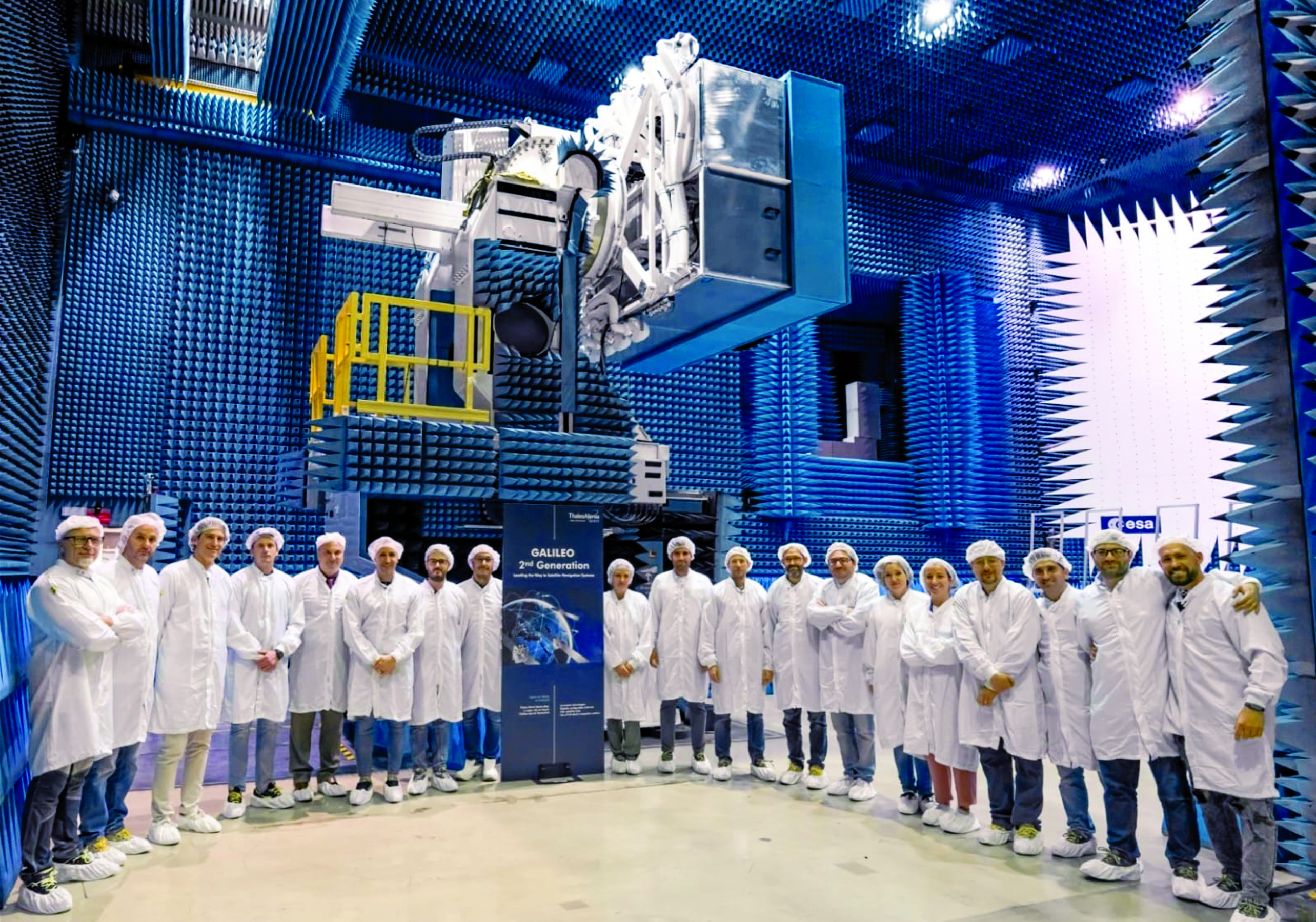
Galileo Second Generation: a constellation of state-of-the-art procurements. (Image: ESA)
An upgrade of the ground control segment in charge of command and control of the constellation is under qualification by the industrial consortium led by GMV. It will provide additional flexibility to allow for deployment in between launches and to address resolution of hardware and software obsolescence, including cyber security, operability improvements and a security monitoring overlay. Furthermore, it will upgrade the Telemetry Tracking and Control (TTC) station in Redu, Belgium, and deploy an additional station in Fucino, Italy, co-located with the Galileo Control Center, bringing to nine the overall number of TTC stations.
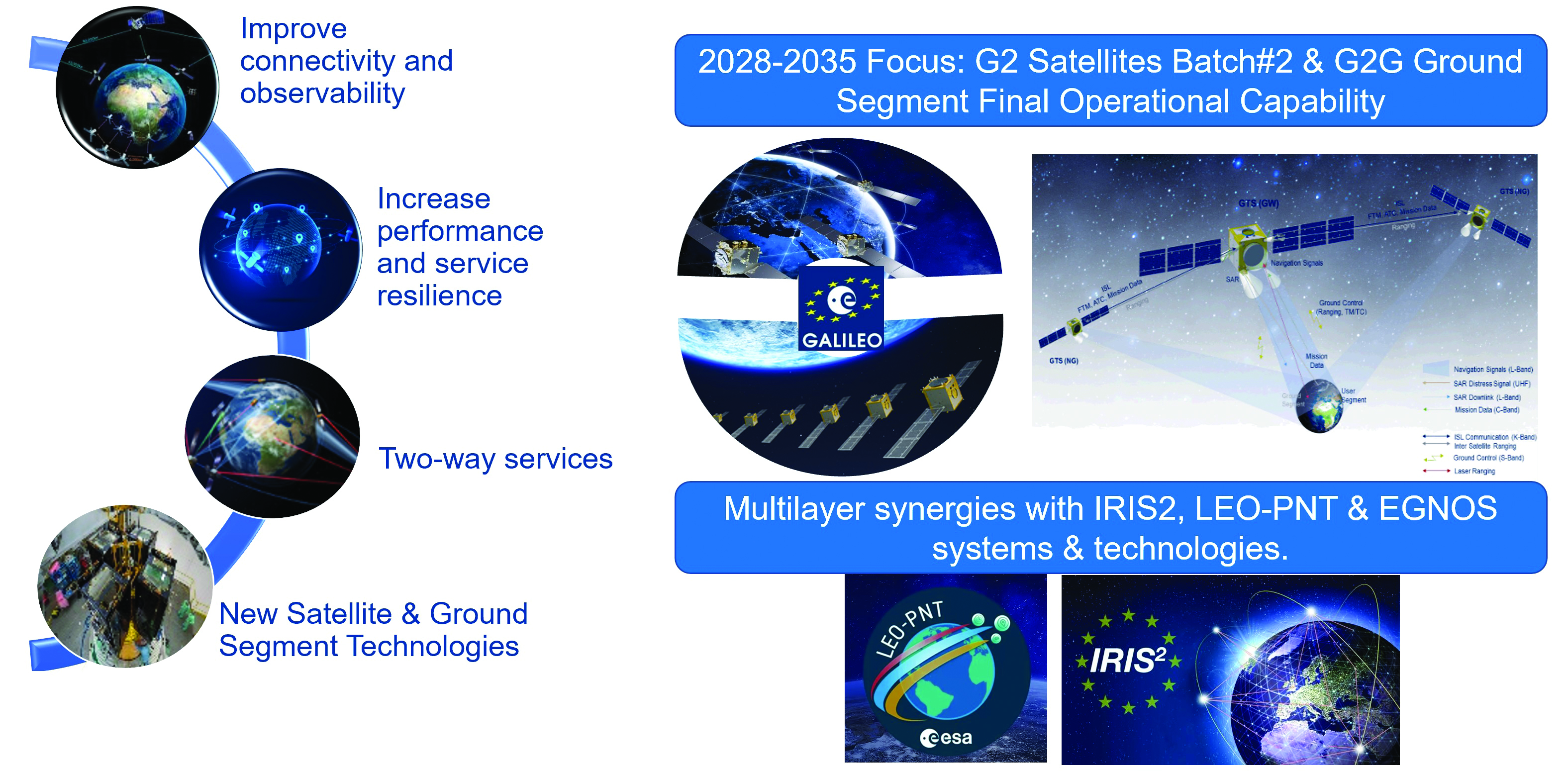
Second generation fast forward
Galileo’s second generation (G2G) will introduce many innovative technologies to offer unprecedented precision, robustness, and flexibility.
For the development of G2G activities 2023 was a key year, with the development of the first batch of G2 satellites, the start of all contracts for in-orbit validation of the ground segment and system test beds and the preparation of the initial operational capability (IOC) design, through the consolidation of the mission/service roadmaps with the EC, EUSPA, and the delegates from EU member states.
This year, Europe has taken the necessary steps to unchain the development of key GNSS features, which will exponentially enhance GNSS accuracy for the worldwide communities in the future:
New and improved services.
Unique flexibility of ground and space systems to enable 12-18 months service time to market, without the need for constellation replenishment.
Upgraded robustness of key infrastructure items.
State of the art GNSS technology leading to centimeter-level precision.
New GNSS signals, including extended data capacity for added value services.
And of course, as a key factor, a full backward compatibility with Galileo First Generation and other GNSS systems.
G2G: Incremental steps for enhanced capabilities over the next decade
The ESA completed the G2G system preliminary design review in July, focused on three key incremental phases of the G2G:
G2G In-Orbit Validation (G2GIOV): specification, design and validation activities for the sake of ensuring the full development of the first batch of G2G satellites and all the associated infrastructure for launch and early orbit phase, in-orbit testing, in-orbit validation, initial enhancement of Galileo services and addition of new Galileo service components.
G2G Initial Operational Capability (G2GIOC): design and specifications required for the complementary procurements that will ensure new Galileo services, as enabled by G2G infrastructure, including both the second batch of G2G satellites and the G2G ground segment.
G2G Full Operational Capability (G2GFOC): Identification of key technological enablers and additional capabilities required for final G2G implementation, including the bridge to future synergies with other EU and ESA programs.
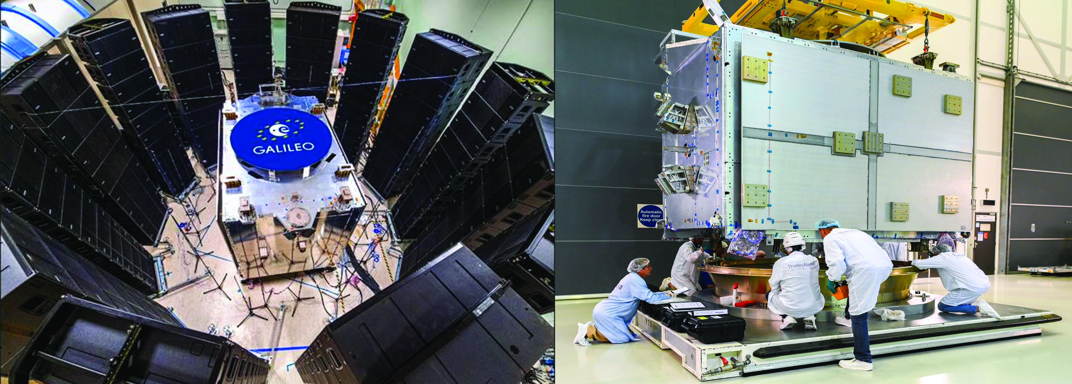
G2G in-orbit validation infrastructure – satellite hardware under validation
G2SB1 acoustic testing in Rome and structural model arrival at ESA ESTEC. (Image: ESA)
The two parallel contracts with Thales Alenia Space and Airbus to develop and manufacture each of six G2G batch one satellites (G2SB1A and B) achieved key milestones this year.
On the G2SB1 satellite A side, the prime contractor tested engineering model payloads and structural models at its premises and delivered them to ESA’s Technology Center (ESTEC). The validation of the new G2G payload capabilities and the key mechanical, vibration and acoustical testing milestones have been achieved.
These satellites will provide the following key innovations: reconfigurable fully digital navigation payload; point-to-point connection between satellites by inter-satellite-link for command and control, and ranging functionalities; electric propulsion for orbit-raising capabilities; advanced jamming and spoofing protection mechanisms; on-board authentication capabilities; increased ground-to-space data rate; and improved time reference (number of clocks and advanced clock monitoring functions).
Key mechanical and launch-related tests on the structural models stacked configurations were performed in the last quarter of this year, in order to simulate the launcher environment and satellite separation dynamics.
On the G2SB1 satellite B and the PHM and RAFS clock manufacturing sides, activities are ongoing as planned, with key HW infrastructure developed and tested in the respective Industrial Primes premises.
This included as key events in 2023 the full testing of the satellite advanced engineering model antenna and the creation of a satellite atomic clock farm in industry premises to produce the more than 70 atomic clocks required for the 12 G2 batch one satellites.
The next steps for these contracts are the completion of the equipment and satellite CDRs, expected in the coming months, in order to engage (starting at the end of 2024) with the critical system compatibility test campaigns of the G2G IOV ground segment infrastructure and system engineering test beds under development.
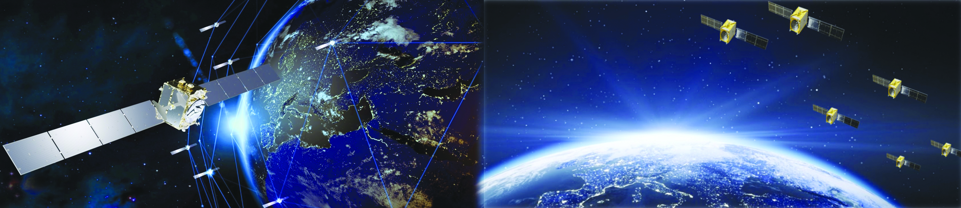
Galileo Second Generation batch one satellites. (Image: ESA)
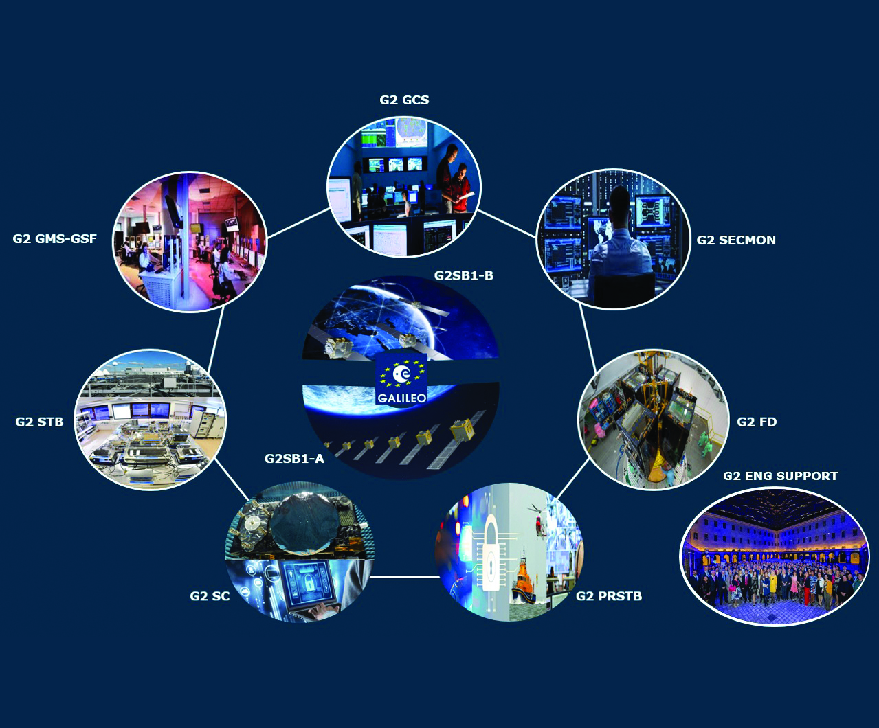
G2G in-orbit validation infrastructure – ground segment and test beds in full development
The key system engineering, ground segment and test beds infrastructure procurements were all awarded during the first semester of 2023, giving EC/EUSPA/ESA and the industrial teams a brief moment of respite and celebration.
Following a competition process that encompassed about 12 months of detailed technical, management and legal interactions, 11 industrial prime contractors were selected for a set of contracts engaging about $1 billion euros of public sector investment:
Four contracts for system engineering, signal and performance, system validation and security and PRS activities.
Four contracts for ground segment in-orbit validation infrastructure.
Three contracts for system test bed activities plus a series of technological developments in the receivers and constellation simulation side.
Once completed in the years to come, these infrastructure developments will ensure not only the launch and early orbit phasing and in-orbit validation of the novel G2G satellite’s capabilities, but also enable the provision to all world users of enhanced Galileo services.
G2G satellites stacked configuration for launcher simulated test at ESA ESTEC. (Image: ESA)
G2G initial and final operational capability moving ahead
In line with the outcomes of the system preliminary design review, two new lines of GNSS improvements are well underway at program level.
In the area of G2G initial operational capability (IOC), which will provide new G2G initial services, an extensive preparatory work has been performed by EUSPA in order to derive the mission needs (as defined by the EC and its Member States), into a set of service evolution roadmaps for the more than one dozen Galileo services.
This work has been supported by ESA dossiers providing incremental implementation of these services, in a continuous improvement ramp-up process, which guarantees backward compatibility and seamless enhancement.
The relevant procurements that will enable, in combination with the in-orbit validation infrastructure, the provision of these services are currently under consolidation:
G2G IOC ground segment, with an initial version to be procured in 2024.
G2G satellites batch two, which is expected to start its competitive procurement procedure in the second part of the EU’s 2021-2028 multi-financial framework.
In addition, work is well advanced in the definition of the key technological developments and system trade-offs that will be analyzed for inclusion in the G2G final operational capability (FOC), expected early in the 2030s.
Critical technologies being analyzed include optical inter-satellite links, advanced governmental payloads, new ground segment and signal technologies and in-space constellation monitoring, among others. ESA expects to complete the preparation of the system-critical design review by the end of 2024 or early 2025 and to submit it for in-depth review by the EC, EUSPA and European member states stakeholders.
Conclusions
Galileo keeps providing continuous and stable services to users with new enhanced capabilities offering high accuracy, authentication and faster time to first fix. The space and ground infrastructure development for the first generation is progressing toward public regulated service IOC and open service FOC.
In parallel, for G2G, hardware production of the new satellites is well under way and the ground segment development has started to maintain Galileo competitive with the other GNSS.
We continue to strive toward achieving the vision defined at the end of the previous decade: “If you can imagine a novel satellite navigation service, we will implement it in 12-18 months.”
Warning sirens about the vulnerabilities of GPS to jamming, spoofing, solar activity and other disruptions have been blaring for many years. Now the U.S. Department of Transportation (DOT), which represents other federal civil departments and agencies on all GPS-related matters within the federal government, might finally be moving from study to action. On September 12, at the annual meeting of the Civil GPS Service Interface Committee held in conjunction with ION GNSS+ in Denver, Robert Hampshire, DOT’s Deputy Assistant Secretary for Research and Technology and Chief Science Officer, announced the release of DOT’s Complementary Positioning Navigation and Timing Action Plan. It aims to drive CPNT adoption across the United States transportation system and within other critical infrastructure areas. You can read more here and download the planhere.
Which GPS vulnerabilities does DOT aim to address and how quickly can it “drive adoption” of CPNT? Attempting to answer these questions requires pushing through a dense thicket of bureaucratic jargon. I asked Karen Van Dyke, Director for Positioning, Navigation, and Timing (PNT) and Spectrum Management in Hampshire’s office four questions. What follows are excerpts from her answers. You can read her full response here.
What is your office’s charter within the federal government to advance the development and deployment of complementary PNT?
Her office’s efforts, Van Dyke told me, “support federal policy governing PNT programs and activities for national and homeland security, civil, commercial, and scientific purposes. These include Executive Order 13905, Strengthening National Resilience Through Responsible Use of Positioning, Navigation, and Timing Services (EO 13905) and Space Policy Directive 7, The United States Space-Based Positioning, Navigation, and Timing Policy (SPD-7).”
Which GPS vulnerabilities and at what scale is this plan addressing?
The action plan, Van Dyke told me, “addresses disruption, denial, and manipulation of GPS for critical infrastructure sectors” on “both a widespread and local scale.”
How and when will this action plan move the federal government’s posture on CPNT from study to action?
Van Dyke cited field demonstrations conducted in 2020 by the Volpe Center of candidate PNT technologies that could offer complementary service in the event of GPS disruptions and a 2021 report to Congress that distilled the PNT resiliency recommendations. DOT, she said, should develop “system requirements for PNT functions that support safety-critical services” and “standards, test procedures, and monitoring capabilities to ensure that PNT services, and the equipage that utilize them, meet the necessary levels of safety and resilience”.
How does DOT intend to engage PNT stakeholders?
Van Dyke pointed to a PNT Industry roundtable that DOT held in August 2022 that included representatives from CPNT technology vendors and critical infrastructure sectors and “informed the development” of the action plan. She also pointed out that on September 11, DOT issued a request for information “as one of the steps to drive adoption” of CPNT services “to augment GPS for the nation’s transportation system, and through the executive branch interagency process, for other critical infrastructure sectors.”
An exclusive interview with Stef van der Loo, market access manager, Septentrio. For more exclusive interviews from this cover story, click here.
What are your key markets and how does this port project fit in?
We have many markets, of course, but we have a big focus on machine automation, mainly for large industrial machinery. Think of agriculture and construction. Port logistics is a newcomer in a sense. In the last 20 years, there’s been a lot of testing with GPS receivers in terminals, but not as much as in construction because the two environments are very different. In a container terminal or port, everything is interconnected and, therefore, complex.
You can equip an excavator with a 3D system and import this data into a building information modeling (BIM) system, but sometimes data is missing and the system breaks. If that happens in logistics the whole chain breaks and you’re stuck. Lately, GNSS has become more popular, especially when coupled with inertial navigation, because the technology has become more capable of delivering centimeter-level accuracy even in challenging environments where the line-of-sight to GNSS satellites may be partially blocked by containers or structures.
So, GNSS is becoming more of a fit for the logistics market.
What have been the drivers of higher accuracy in the past 20 years?
The terminal operators want to increase their throughput of containers. Automation will not always speed up the handling of containers, because autonomous vehicles might move slower than those operated by experienced human operators.
In logistics they started looking at positioning to deal with the loss of containers. Every year, every terminal stacks a certain number of containers, but not all the information about them is given to the terminal operating system (TOS) automatically. If you keep on stacking but with missing data every container on top of a missed one will be wrong, so you fill your system with wrong data. Sometimes, operators must search for misplaced containers, which may require stopping operations and deploying additional personnel. Additionally, it is not very safe to go into these yards. This is one reason why ports began to deploy positioning systems. However, ten years ago, with meter accuracy, they were failing all the time. Now, improvements in the technology have enabled GNSS to become fit for the challenge.
Nowadays, in terminals, you see many non-GNSS positioning systems, such as radar systems, to steer cranes and position containers. We’re replacing many of these systems. There are also transponders in the roads, for vehicle traffic management and for area guided vehicles (AGVs), which are fully autonomous and need centimeter-precision everywhere. GNSS does not work everywhere. You always have some disruptions or gaps in coverage. However, the newer inertial systems can compensate for short GNSS outages so that you get reliable centimeter accuracy. Additionally, the cranes are increasingly automated. Gantry cranes, for example, are on rubber tires but constrained in their movements. Reach stackers, forklifts, and terminal tractors, on the other hand, have free movement. These vehicles are typically equipped with the GNSS or INS systems for traffic management or container and cargo positioning.
The next step would be to move to semi- or fully-autonomous vehicles, of course. GNSS is not enough for that; autonomous technology needs to have different sensors. It’s extremely difficult to prove and to test a new system in a terminal, because it’s an uninterrupted chain of interconnection between the sea, the stacking of the containers, and ground transportation. You cannot just go in with an autonomous forklift or an autonomous reachstacker and try out something. However, you can only prove it when you do it in that chain. Otherwise, it’s a standalone kind of test. So, that’s the biggest obstacle.
Don’t containers have a barcode you can scan or a serial number you can see with a camera?
Yes, they do. The problem is not so much the number on the container but its virtual number in the terminal’s layout. Let’s say that you put container A on square C1. What if you deviate half a meter and TOS puts it automatically in the system in C2 instead? That’s often where mistakes occur. So, you can have OCR scanners and easily scan the code on the container. The problem is where you place the container.
What about the virtual image of all the container stacks?
Yes, the digital twin, like in construction. However, in construction you don’t need the infrastructure. You don’t need to install a radar in a certain place, calibrate it, enter it in the maps, et cetera. That’s more the survey part of construction. The biggest win is when you can equip a vehicle with a standalone system. It needs RTK, but it is standalone for the port. You don’t need large infrastructure, you don’t need to drill holes every two meters to place transponders in the roads in the whole area, perhaps just a small part. That saves them a lot of investments and maintenance.
In terminals, you can use GNSS or INS systems for vehicle traffic management, autonomous vehicles and tasks, or to get the position of a container. For example, when a reach stacker reaches into a stack and locks a container in place, it’s crucial to have a very reliable centimeter-level position. Errors grow as the data is processed from the control systems to the TOS. To know for certain the position of a container when it was placed in a stack errors must not exceed half a meter. Therefore, the reliability and accuracy of the GNSS/INS is crucial for container positioning.
Many AGVs carrying containers still work with road transponders. But if we can assist with our GNSS and INS products, they may be able to make a hybrid form of terminal. In perhaps 80% to 90% of the terminal, GNSS/INS works fine because you have a relatively clear view of the sky.
We already play a big role with Kalmar. They are replacing all legacy positioning systems, which are often heavy on the infrastructure side. So, they’re stuck in their layout, they are not flexible anymore. To handle the positioning of the containers, they preferably do not use any fixed infrastructure. That’s one of the drivers within their SmartPort automation service. So, it’s for flexibility, for traffic management, automation and to position the containers.
The autonomous side is a whole other category. There are many semi-autonomous terminals and they’re partly closed, so nobody can enter them. There you need to do everything fully autonomously, of course, because there are no people inside. Here, too, the Septentrio systems play a role, similar to that of other autonomous vehicle markets. Yet the autonomous terminal evolution is still in its early days. The non-container logistics might take a leap here. We have an increasing number of customers who are developing or retrofitting autonomous logistics vehicles such as the terminal tractors, reach stackers and forklifts mentioned before, specifically for yards and factory plants.
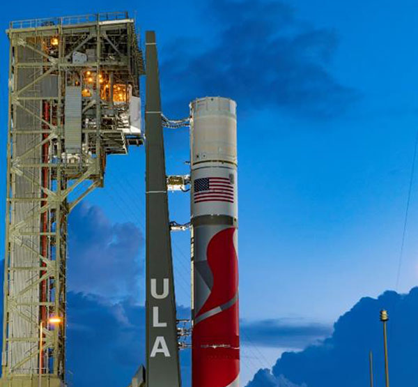
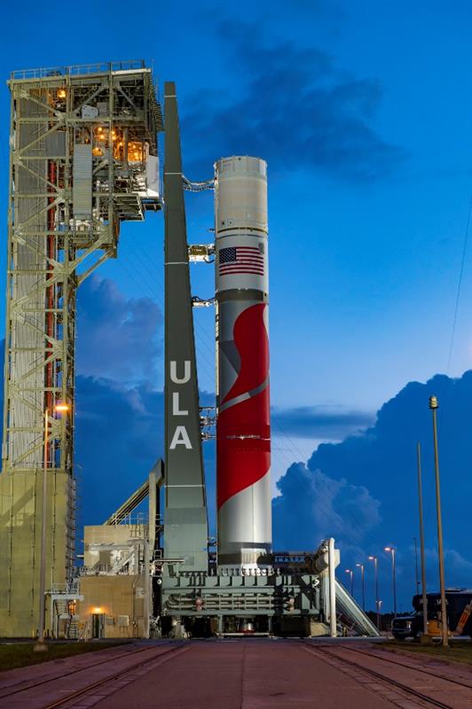
The ULA Vulcan Centaur launch vehicle. (Image: ULA)
The United States Space Force’s Space Systems Command (SSC) has assigned 21 launch service mission assignments for the National Security Space Launch (NSSL) Phase 2 Launch Service Procurement contract. This is the fifth and final order year in the Phase 2 contract.
United Launch Alliance (ULA) received 11 mission assignments and SpaceX received 10. These missions are scheduled to launch over the next two to three years and focus on a variety of mission areas.
The 11 missions assigned to ULA are: GPS III-9, NROL-73, NROL-56, STP-5, SILENTBARKER 2/NROL-118, GPS IIIF-1, NROL-100, USSF-95, NROL-109, SDA T2TL-B and USSF-25.
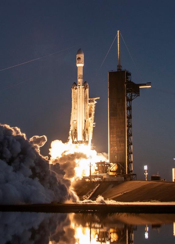
The 10 missions assigned to SpaceX are: SDA T1TL-F, SDA T1TR-A, USSF-57, NROL-77, SDA T1TR-E, GPS III-10, USSF-75, SDA T2TL-A, SDA T2TL-C and USSF-70.
NROL-77, NROL-73, NROL-56, NROL-109, and NROL-100 are missions being conducted in partnership with the National Reconnaissance Office (NRO).
T1TL-F is the last mission of six Space Development Agency (SDA) Tranche 1 Transport Layer launches. T2TL-A, T2TL-B and T2TL-C are the first three Tranche 2 Transport Layer launches. SDA’s Transport Layer aims to provide assured, resilient, low-latency military data and connectivity worldwide to the full range of warfighter platforms.
T1TR-A and T1TR-E are the last two SDA Tranche 1 Tracking Layer launches. The Tracking Layer aims to provide global indications, warning, tracking and targeting of advanced missile threats, including hypersonic missile systems.
The GPS III-9 and GPS III-10 missions are the final projected GPS III missions. The GPS IIIF-1 is the first launch of the follow-on GPS III satellites. GPS Block IIIF introduces several improvements and novel capabilities compared to previous GPS satellite blocks.
SpaceX’s Falcon Heavy launch vehicle. (Image: SpaceX)
USSF-57 will launch the first of three next generation overhead persistent infrared GEO satellites. These satellites will deliver survivable, resilient missile warning, tracking, and defense in a highly contested and congested space domain.
SILENTBARKER 2/NROL-118 is a joint NRO and SSC Space Domain Awareness mission to meet U.S. Department of Defense (DOD) and intelligence community space protection needs.
USSF-25 will launch the Defense Advanced Research Projects Agency’s Demonstration Rocket for Agile Cislunar Operations (DRACO). The goal of the DRACO program is to demonstrate nuclear thermal rocket in orbit.
USSF-95 will be the first launch of a missile track custody (MTC) prototype satellite. The MTC prototype effort will evaluate the ability of various next generation overhead persistent infrared sensor designs to meet missile tracking requirements.
STP-5 is the latest mission in support of SSC’s Space Test Program (STP). The STP performs mission design, payload-to-bus integration, space vehicle-to-launch vehicle integration, and on-orbit operations for science and technology payloads that exhibit potential military utility. STP-5 will launch two satellites in support of the DOD’s Strategic Capabilities Office.
“Seen & Heard” is a monthly feature of GPS World magazine, traveling the world to capture interesting and unusual news stories involving the GNSS/PNT industry.
Researchers in Alaska tracked the migration patterns of olive-sided flycatcher birds by attaching tracking devices to them to discover why their population is declining. The songbirds travel more than 15,000 miles every year to South America and then back to Alaska. To survive the long trips, they require safe locations to rest during their journeys. The researchers believe the stopover sites may provide an answer to the declining population. During the five-year study, the researchers deployed 95 devices and recovered only 17. The data pointed to 13 stopover sites between Washington and Peru as well as their wintering areas in South America.
Crime ring members caught
Image: hdagli/E+/Getty Images
Members of an organized crime ring in the Florida Keys who are accused of stealing more than $2.5 million in boating navigation devices have been arrested, reported Local 10.com and Fox 4. Eleven men have been accused of targeting multiple marinas throughout Florida and stealing navigation devices from boats, specifically Garmin devices. For example, a Garmin 8612 H16 Model can be sold for more than $5,000. Ten suspects are in custody and are facing more than 122 charges.
A new study published in Science used tracking devices on 43 animal species during the 2020 COVID-19 lockdowns to find that wild animals emerged from their natural habitats and ventured closer to the roads and cities that were empty. The study used several methods to analyze tracking data. Researchers examined how much animals moved on an hourly basis and during a 10-day period. Across species and countries, on average, hour-to-hour movement was 12% lower in the spring of 2020 compared to the same period in 2019. With the end of lockdowns, human activity returned to normal, and animals had to adapt again. The results of the study demonstrate how humans can change their own behavior to lessen their impact on animals.
Navigation meets creativity
Image: @vikas_ruparelia on Twitter
A man from Bengaluru, India, Vikas Ruparelia, used the Strava navigation app to trace the country of India to celebrate its Independence Day. Ruparelia started and ended his journey at the Mahatma Gandhi statue near Orion Mall in Rajajinagar, India. He covered more than 73 km on foot in 17 hours. The Strava app enables users to track their running and hiking routes as well as join challenges. The route Ruparelia took was designed by another user of the app.
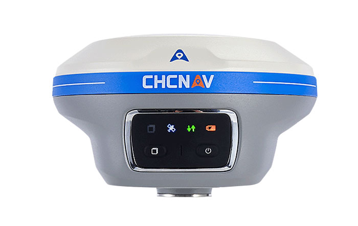
CHC Navigation (CHCNAV) has released the i89, a compact IMU-RTK GNSS receiver with visual surveying and 3D modeling capabilities. In addition to GNSS surveying, the i89 offers augmented reality surveying to capture accurate 3D coordinates where signals are obstructed or access is limited.
The i89 combines CHCNAV’s iStar2.0 software and a 1408 channel GNSS system-on-a-chip (SoC) module for full constellation tracking. According to the company, its advanced algorithms improve data quality by 20%, offering RTK accuracy and reliability even in low latitude regions with high ionospheric interference.
Based on video photogrammetry, the i89 dynamically extracts accurate 3D coordinates from real-world video. Coupled with its IMU, it is designed to improve photogrammetry efficiency and accuracy. It complements UAV surveys by resolving typical distortions from UAV-mounted cameras.
The i89 offers 16.5 hours of battery life, weighing only 750g and is IP68-rated to withstand a 2m pole drop. Its visual navigation and staking capabilities aim to simplify field operations and ensure optimal productivity for surveyors in a wide range of everyday surveying tasks.
GNSS is like opium. Highly addictive, pleasing to the user, but laced with peril when you’re hooked. GPS World readers are well aware of the vulnerabilities, and probably aware of the serious concerns governmental bodies have about our reliance upon it. Here, we consider not so much how it can fail as what the impact of failure is on society, and what mitigations exist to minimize those impacts.
Impact on society
The most commonly cited causes of GNSS failure are jamming (unintentional and intentional) and spoofing. Less well appreciated are solar weather, satellite system errors, receiver system errors and, most importantly, cybersecurity-related errors. Any of these can cause a significant disruption to how society functions today.
The U.S. Department of Homeland Security identified that 15 out of the 18 Critical National Infrastructure sectors were vulnerable to GNSS failure: communications, emergency services, information technology, banking and finance, healthcare and public health, energy (electric, oil and gas), nuclear, dams, chemical, critical manufacturing, defense industrial base, postal and shipping, transportation, government facilities, and commercial facilities.
The threat is real and present. Conflicted areas are routinely jammed and spoofed. Even in peace, GNSS is fragile. In the past year, GNSS interference led to a runway at DFW airport being closed, a 33-hour GNSS outage in the Denver metro area, and even a recent Melbourne Formula One race had to be stopped for 40 minutes due to GNSS data problems.
Mitigations
In most cases, no alternate references are in place, and without them, it is difficult to know that the GNSS data being received is wrong. The ship Stena Impero, for example, was seized by Iran for being in its territorial waters. It is thought to have been victim to spoofing that led it there, but proving it is difficult.
Alternate references exist at low cost, but they generally divide “PNT” into “PN” and “T”, and whether on land, at sea or in the air. On land, most requirements are related to “T” because most applications, such as broadcast facilities and data centers, don’t move, and even when they do, there are enough landmarks available to at least make a sanity check. At sea and in the air, by contrast, motion is the reason we are there, there are few landmarks to confirm location, hence “PN” dominates.
For “T”, armageddon clocks can provide holdover for brief interruptions. However, they must be sufficiently tested to ensure that they succeed. In the Denver incident, radio systems had rubidium clocks for backup, but they drifted too far during the outage to be useable, whereas cellular networks, with alternate terrestrial timing sources, continued to work. Terrestrial time distribution systems over existing IP infrastructure, which Hoptroff supplies, work well globally, but are restricted to land-based time synchronization applications.
For “PN” and “T”, in air, sea and land, low-Earth orbit satellite services such as Satelles, Starlink and OneWeb provide global solutions. Their signals are much stronger than GNSS and therefore are much harder to jam or spoof, but they remain susceptible to interferences such as space weather, which destroyed 40 Starlink satellites on launch last year. However, as the Denver incident shows, until you test the solution, you never really know what might go wrong. eLoran terrestrial wireless solutions are very effective but limited in reach to within a few thousand miles of terrestrial transmitters. Such systems are being installed in South Korea and Saudi Arabia due to their proximity to hostile neighbors. They are likely to be installed in North America and Europe within the next decade.
What all these solutions have in common is that, while they are not expensive, they are not free, and are only available under license. Sovereign GNSS providers have, to date, provided PNT signals at no cost to the consumer. It must be accepted in the new landscape, not just that PNT is no longer free, but also that the supplier can choose its customers. Sovereign GNSS access could be restricted at the whim of a president. Private services are already selective — Starlink chose to provide the Ukraine with service during the current conflict, but it has no obligation to continue to do so.
Get on with the risk register
One of the biggest problems with preparing alternatives to GNSS is that the risk is ignored until it has started to have an impact on business and society. This can be addressed by ensuring that resilient PNT is on corporate and institutional risk registers. It is starting to happen now that governments have started to raise concerns. However, we have a way to go before inclusion on risk registers is a foregone conclusion.
This year marks 50 years since the U.S. Department of Defense approved the design for GPS and first funded the program. It is also the 30-year anniversary of an important milestone – initial operational capability of GPS. Please don’t let its longevity fool you into thinking it is past its prime! GPS is, and will remain, one of the most innovative systems ever designed, funded and operated by the U.S. government.
Today, GPS represents a highly successful public and private partnership, one in which diverse stakeholders continue to coordinate through fora such as the National Executive Committee for PNT and its Advisory Board. and the Civil GPS Service Interface Committee. How did this system become a military, public safety, critical infrastructure, and economic success? The world-class GPS community is made up of the teams and individuals who design, develop and operate these critical technologies as well as the people and organizations that benefit from its applications. From pioneers, scientists, engineers, and Guardians to civil servants, lawmakers, and entrepreneurs, the GPS community has transformed, is transforming, and will continue to transform lives across the globe, and soon, the moon.
GPS World highlighted the important roles played by many early GPS pioneers in a two-part series aptly titled, “Heroes” in the May and June 2010 issues. It has also covered Dr. Gladys West, who is one of the most consequential mathematicians and programmers to contribute to the global success of GPS. Her geodetic models helped refine our understanding of Earth’s shape, which proved fundamental to the success of GPS and its myriad applications. In 2021, the Trimble Foundation established the Dr. Gladys West Scholarship Program. Virginia State University (her alma mater!), North Carolina A&T State University, and Florida International University award four-year scholarships to one student per year to honor Dr. West’s achievements as a woman of science and a woman of color.
A celebration of GPS must also recognize our lawmakers — the people who authorize and appropriate funding for GPS and its augmentation programs. Nearly every U.S. federal department and agency uses these systems to fulfill their missions on behalf of the American people. They also leverage their technical, programmatic, operational, and experiential expertise to ensure that GPS and its augmentation systems remain the best in the world. This work is possible thanks to congressional committees, members of Congress, and staff. The Senate Appropriations and House Appropriations committees, the Senate Armed Services and House Armed Services committees, the Senate Commerce, Science and Transportation and the House Energy and Commerce committees, the GPS Caucus and many more members of Congress, provide critical oversight and funding. Their support ensures that GPS continues to bring $1.7 trillion and counting in economic benefits to the U.S. economy, creating hundreds of thousands of jobs while enhancing national security, public safety and critical infrastructure.
The future is bright for GPS manufacturers and those developing new applications. To realize their success, projects funded by the Infrastructure and Investment Jobs Act and the Inflation Reduction Act will depend on GPS to continue to deliver signals that are accurate, have integrity, and are available and continuous in nature. The next enterprising GPS entrepreneur is waiting in the wings
Thanks to a network of determined individuals, GPS-driven technologies — used to support precision agriculture, safe transportation, synchronized global banking, cutting-edge emergency response, elite and amateur sports, and more — are transforming our lives, creating jobs, and promoting growth across the economy.
GPSIA joins other members of the GPS community by celebrating 50 years of GPS and looks forward to the innovations and applications that will shape the next 50 years and beyond.
A roundup of recent products in the GNSS and inertial positioning industry from the October 2023 issue of GPS World magazine.
SURVEYING & MAPPING
GNSS Receiver For GIS and survey professionals
The R2 GNSS system is a compact, durable, and flexible GNSS receiver that collects highly accurate data in a wide range of geospatial applications with submeter to centimeter positioning accuracy. The R2 can track the full range of GNSS satellite constellations and augmentation systems, and also comes with an integrated Trimble Maxwell 6 chip and 220 channels. Users can achieve higher accuracy in real-time with the ability to choose correction sources from traditional real-time kinematic, VRS networks, to Trimble RTX correction services delivered by both satellite and internet/cellular. The R2 can provide improvements to position availability and accuracy when heavy overhead cover, such as tree canopy and buildings, obstruct satellite signals. The receiver is also IP65-rated, making it suitable for rugged environments. Trimble Geospatial, geospatial.trimble.com
Scanning and Mapping Solution Designed for accuracy-focused remote sensing applications
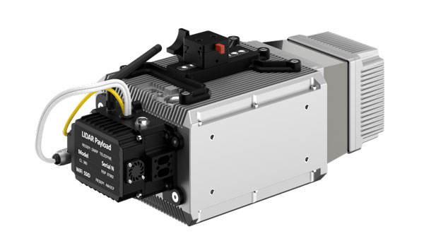
The Resepi Teledyne Optech CL-360-HD has a powerful four-return laser and increased range of up to 750 m, making it ideal for mobile mapping, forestry and crack detection in critical infrastructure areas such as airport runways. Resepi is a sensor-fusion platform designed for accuracy-focused remote sensing applications. Resepi utilizes a high-performance INS and a high-accuracy dual antenna GNSS receiver, integrated with a Linux-based processing core and data-logging software. The platform also provides a Wi-Fi interface, optional imaging module, and external cellular modem for RTCM corrections. Resepi can be operated by a single hardware button or from a wirelessly connected device via a simple web interface. Resepi, equipped with Teledyne’s CL-360HD lidar, offers various laser scan speeds and frequencies, allowing users to tweak the settings to match their individual needs. Inertial Labs, inertiallabs.com
GNSS Receiver Series Available in three different models for various applications
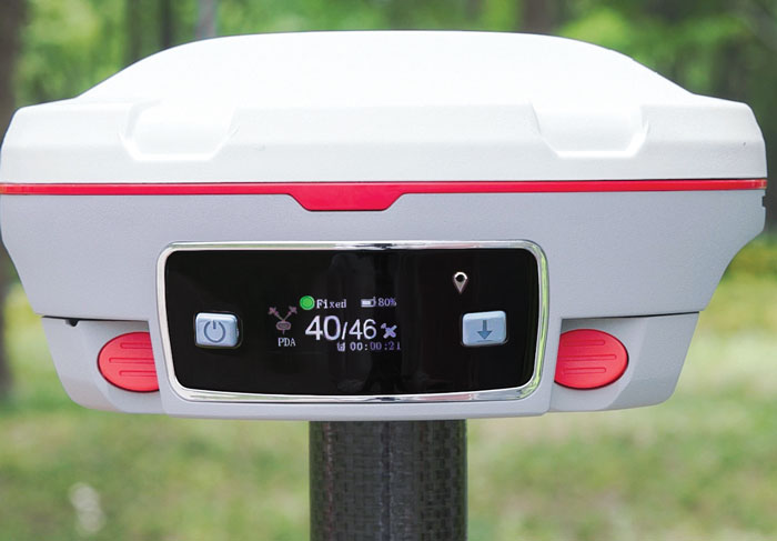
The Xtraordinary X1-series GNSS receivers include X1 and X1 Lite and X1 Pro. The X1-series adopts Linux OS, which improves the stability of the system and the synergistic compatibility of each module. This series of GNSS receivers features improvements to satellite tracking, the inertial measurement unit (IMU), battery life, and more. Optimized with a new generation of IMU module, users can easily initialize the IMU in 5-sec and start tilt measurements up to 60°. The X1-series GNSS receivers supports both 4G/radio correction data transmission and can reach up to 15 km range in enhanced internal UHF mode, 20 km range in external mode, and more than 50 km via internal GSM or PDA CORS mode. SingularXYZ, singularxyz.com
GNSS Smart Antenna For agricultural, marine, GIS, mapping and other applications
The A631 combines the Athena GNSS engine and Atlas L-band correction technologies with a new web user interface (WebUI). Optional features include 16 GB of internal storage, Bluetooth and Wi-Fi. The compact antenna is designed for rugged environments and meets IP67 requirements. With multiple operating modes, A631 can be used as an RTK base station or rover. The device is supported by the Atlas Portal, which empowers users to update firmware and enable functionality, including Atlas subscriptions for accuracies from meter to sub-decimeter levels. A631 also supports BaseLink and SmartLink modes. SmartLink allows users to directly connect AtlasLink as an extension to any existing system that has industry-standard connectivity options. BaseLink automatically sets up AtlasLink as a permanent reference station, delivering corrections to any other GNSS receiver being used for positioning. Hemisphere GNSS, hemispheregnss.com
GNSS Receiver For land surveying, GIS, and construction applications
The Mars Pro combines GNSS, inertial measurement unit (IMU), and laser technologies. When set to laser mode, the Mars Pro can carry out measurements by selecting a signal-friendly spot within a 10-m radius, which aids in measuring hard-to-reach, signal-obstructed, and hazardous areas. With its millimeter-level laser distance meter integrated on its rear, the Mars Pro facilitates the utilization of the laser mode in scenarios involving surveying and stakeout. The integrated IMU sensor offers 60° tilt compensation, which remains functional even when operating in laser mode, allowing for uncompromised efficiency and accuracy. Equipped with the latest K8 platform, it boasts full-constellation support, offering 1,668 tracking channels and more than 60 satellite tracking capabilities across all existing and planned constellations — GPS, GLONASS, Galileo, BDS, QZSS and IRNSS. The Mars Pro offers support for precise point positioning (PPP) service, enabling rapid fixing within seconds. Its dynamic OLED color screen is sunlight readable and offers real-time visualization of essential data — satellite count, fixed state, on-off state, power, and more. It is compatible with mainstream brands and multiple protocols, such as Transparent, TT450S, SATEL, Trimtakl3, CHC and South. ComNav Technology, comnavtech.com
Lidar System For mobile mapping applications
The AlphaUni 20 lidar system (AU20) features advanced multi-target capabilities that support up to 16 target echoes for vegetation penetration. The AU20 captures ground surfaces with extreme precision, producing accurate digital elevation models and digital surface models in challenging environments. The lidar system has an accuracy of 2 cm to 5 cm. It has a lightweight, compact design that weighs 2.82 kg in its airborne configuration and a total of only 10.7 kg with its car mount kit, including a Ladybug5+. Its flexible multi-platform design allows users to install it on manned or unmanned aircraft for aerial scanning, integrate it into a variety of land vehicles, and even use it as a backpack-mounted system for mapping narrow areas. CHC Navigation, chcnav.com
Gyroscope An advanced performance, tactical-grade MEMS gyroscope solution
Developed for use in particularly harsh environments, the TAG-304 gyroscopes can withstand extreme shock and vibrations in accordance with MIL-STD-810 standards. Additionally, TAG-304 gyroscopes are fully digitized (RS-422 interface), include built-in test (BIT) functionalities, and have no moving parts. TAG-304 is an advanced performance, tactical-grade MEMS gyroscope, of which size, power consumption, reliability and performance are ideal for accomplishing complex tasks requiring accurate stabilization of assorted platforms. Very low latency (group delay), small size, 4K Hz data rate, 1K Hz bandwidth, and low noise make TAG-304 gyroscopes a suitable solution for miniature electro-optical systems, gimbals, line-of-sight, and pan and tilt platforms stabilization and pointing applications. Inertial Labs, inertiallabs.com
IMU For GNSS-challenged environments
The ANELLO IMU+ provides robust and reliable autonomous navigation and positioning in GNSS-denied or GNSS-compromised environments. Powered by optical gyroscope technology, the ANELLO IMU+ delivers high precision and reliability in demanding conditions, including shock, vibration, electromagnetic interference and temperature. The ANELLO IMU+ is suitable for autonomous applications in the construction, robotics, mining, trucking and defense industries.The device delivers long-term dead reckoning in high-temperature and high-vibration environments.The ANELLO IMU+ features unaided heading drift of < 0.5°/hr, dual high-speed CAN FD interfaces, and dual RS-232 interfaces; has ASIL-D ready, automotive-qualified CPU and OS; and is IP68 waterproof, resistant to dust, salt spray and chemicals. ANELLO Photonics, anellophotonics.com
Flying Laser Scanner Captures colorized 3D point clouds for producing 3D models, drawings, and visualizations
BLK2FLY is a fully integrated lidar UAV laser scanner with advanced obstacle avoidance for reality capture from the air. It can scan inaccessible areas such as rooftops, facades and large building interiors. BLK2FLY autonomously captures interior and exterior dimensions and features of buildings with a few taps on a tablet. Users can select an area within the map on their tablet and the BLK2FLY will create its own flight path to scan it quickly and safely. Users can send the BLK2FLY to scan a new area by tapping anywhere on the 3D view in the app. The BLK2FLY also can be piloted manually with virtual joysticks on a user’s tablet.
BLK2FLY can scan interiors of large arenas, stadiums, facilities, plants, and even obscured or confined outdoor areas with its Indoor Mode, which allows the BLK2FLY to get closer to objects with reduced flight speed and to fly within confined spaces without access to GNSS. With advanced obstacle avoidance and increased visual SLAM capabilities, the BLK2FLY’s Indoor Mode makes scanning inside fast and versatile. Leica Geosystems, leica-geosystems.com
MOBILE
Smart Antenna Suitable for multiple applications
The HCS885XF/HCS885EXF smart helical GNSS antenna is suitable for UAV, land survey devices, automotive positioning, and other precise positioning/heading applications. The HCS885XF/HCS885EXF combines the performance and light weight of the Tallysman dual-band (GPS/QZSS L1/L5, GLONASS G1/G3, Galileo E1/E5a/b, BeiDou B1/B2/B2a) HC885SXF antenna with the low power consumption and GNSS augmentation capabilities of the u-blox NEO-F9P GNSS receiver. HCS885XF/HCS885EXF employs L5 signals (1160-1217 MHz), which transmit stronger signal power and a higher bandwidth chipping rate than L2 signals, thereby offering high performance when challenged with strong multipath signals. It also employs Tallysman’s eXtended Filtering system, which mitigates near-band and out-of-band interference, such as LTE signals and their harmonics and the planned Ligado service in North America, enabling operation in the most challenging deployments. The HCS885XF/HCS885EXF integrated receiver can simultaneously monitor four constellations, support base/rover RTK configurations (<1 cm), and use u-blox PointPerfect PPP-RTK augmented services over a terrestrial control network (3-6 cm). A moving-base precise heading configuration is available with base/rover antenna pairs. Tallysman Wireless, tallysman.com
Antenna Multi-constellation antenna for precision agriculture and semi-autonomous or autonomous applications
The TS122 EUAA provides centimeter-level accuracy in highly variable terrain and challenging GNSS-obstructed environments with ± 10 cm P2P accuracy and STANDALONE technology. The TS122 EUAA smart antenna receives dual-frequency multiple constellation signals from GPS, GLONASS, Galileo and BeiDou, with output position information up to 10 Hz. The antenna is capable of correcting deviations caused by a vehicle’s roll and pitch while working on uneven groups or slopes. Harxon, harxon.com