In universities across the world, theory lays the foundation, but in the field, realism builds true expertise.
For students studying GNSS engineering, textbooks and simulations alone are no longer enough. Tomorrow’s engineers need to use the same applications and work with the same complex environments that professionals face in the real world. This means using tools that generate actual RF signals, not just software abstractions — tools that recreate urban canyons, interference, jamming, spoofing and satellite dynamics with precision.
Safran has established the Minerva Academic Partnership Program, an initiative that brings its Skydel GNSS Simulation Engine to qualified educational institutions worldwide.
A Modern, Software-Defined Approach to GNSS Simulation
At the heart of this initiative is the Skydel simulation engine, a software-defined GNSS simulator. Built to leverage commercially available off-the-shelf (COTS) hardware, Skydel eliminates the need for proprietary hardware. It delivers the full spectrum of satellite constellations — as well as LEO ones — and frequency bands. By integrating Skydel in their projects, researchers now have the tools to pursue ambitious ideas with confidence, such as:
■ Designing and testing custom signals or constellations not yet in existence
■ Simulating real-world scenarios that can include both environmental and man-made interference
■ Integrating and testing additional sensors and platforms through open-source plug-ins and hardware-in-the-loop setups
■ Conducting rigorous resiliency testing against jamming and spoofing in a controlled, repeatable environment without real-world risk
■ Building their own simulator with existing hardware components around Skydel
Empowering the Next Generation of PNT Innovators
Through the Minerva program, Safran provides full-feature Skydel licenses for faculty and student use, creating an environment where learning and innovation thrive. This initiative not only eliminates the barrier to entry but also fosters collaboration between academia and industry –— fueling a new wave of GNSS advancements.
A Global Initiative
Today, Minerva includes more than 80 member institutions and boasts a growing portfolio of peer-reviewed publications and conference presentations.
“This momentum highlights the real-world impact of the program and its role in driving local research excellence and fostering a vibrant, collaborative international GNSS community,” said Pierre-Marie Leveel, program director of PNT simulation at Safran Electronics & Defense. “Safran Electronics & Defense’s Minerva program is more than just a software — it’s a mission to democratize GNSS simulation and nurture the next generation of PNT researchers. As innovation becomes more critical to national sovereignty, transportation, and space exploration, empowering students and researchers has never been more vital.”
Elevating GNSS Simulation
The evolution of Safran Electronics & Defense’s GNSS simulators — across both software and hardware — has been shaped by the growing demands of users and the broader market.
“The demand for multi-vehicle and multi-antenna scenarios has never been higher, and the same can be said for interference simulation,” said Pierre-Marie Le Veel, program director of PNT Simulation at Safran Electronics & Defense.
To address these challenges, Safran’s GSG-7 and GSG-8 Gen2 simulators are engineered to handle a range of applications, from basic to advanced GNSS jamming and spoofing resiliency testing.
The GSG-7 simulator is designed for location-aware applications and systems that depend on navigation or timing. With high-end performance — featuring a 1,000 Hz simulation iteration rate, high dynamics, real-time synchronization, and all-in-view satellite signal simulation — the GSG-7 is well-suited for development and integration projects that demand high performance and extensive constellation licensing. It supports multi-constellation and multi-frequency GNSS simulations and can be configured to operate with all current and upcoming GNSS signals.
Meanwhile, the GSG-8 Gen2 is the latest iteration of Safran’s GSG-8 model, offering flexible simulation capabilities for any device that relies on GNSS signals. Built on Safran’s Skydel-based simulation platform, the GSG-8 Gen2 helps users model scenarios.
Powered by high-end GPUs, the GSG-8 Gen2 offers reliable and precise GNSS signal testing. It can simulate thousands of signals, run multiple instances at once, and introduce jamming and spoofing to evaluate system resilience. The turnkey system features a redesigned chassis for greater connectivity, including six front-facing, high-quality RF outputs, a combined output covering the full GNSS bandwidth, and the same high-end simulation iteration rate as the GSG-7. This allows users to quickly get up and running with complex simulation requirements.
“The market is also demanding realism,” Le Veel said.
All Safran simulators are powered by the Skydel Simulation Engine, which is updated quarterly. Each release introduces new features, signals, and enhancements, enabling more authentic simulations and offering the flexibility to create virtually any GNSS testing scenario.
Staying Ahead of Market Changes and Signal Threats
The recent increase in signal interference threats has driven the demand for enhanced positioning, navigation and timing (PNT) resilience, leading to the broader use of both conducted and over-the-air (OTA) testing. The anticipated deregulation of controlled reception pattern antenna (CRPA) technology also is expected to open the door for civilian markets to perform testing.
“Throughout the past few years, Safran Electronics & Defense has massively revamped our approach to the Wavefront platform and now offers the GSG-Wavefront for those testing CRPA antennas against jamming and spoofing threats,” Veel said.
The ability to safeguard GNSS networks from jamming and spoofing attacks has never been more vital. Achieving this level of resilience calls for a GNSS simulator that can generate dedicated RF signals for evaluating the effectiveness of CRPA architectures.
Safran’s GSG-Wavefront, featuring a shared local oscillator (LO) design, stands out as a field-proven, off-the-shelf solution for CRPA receiver testing. It has a customizable platform that offers upgradable options powered by Skydel — the company’s GNSS simulation engine.
Le Veel added, “We are working hard to keep up with demand in both the defense and civilian markets.”
In addition, Le Veel noted that Safran’s GSG-Anechoic is attracting attention from users who work with anechoic chambers, thanks to its multiple, independent RF outputs, automatic antenna mapping, and built-in calibration features for delay and power loss.
Safran Electronics & Defense supports a wide array of users in both the civilian and defense sectors, spanning aerospace, critical infrastructure and transportation. In recent years, however, the company has seen its fastest growth in the New Space market. Safran’s simulators are used in a range of cutting-edge applications, including satellite navigation, low-Earth orbit (LEO) constellations, and rocket launch and landing systems.
“We are proud that the flexible tools and features we have included in Skydel are being used in these incredibly robust applications,” La Veel said.
A challenge for most GNSS simulation suppliers is ensuring compatibility and coherence with a wide range of GNSS receivers. La Veel shared that Safran Electronics & Defense is in a unique position, as it also designs and manufactures its own receivers, such as the newly released Skylight.
“Additional challenges can arise when developing new signals or constellations, such as the newest LEO ones, said La Veel. “Our close partnerships with both Xona Space Systems and TrustPoint have allowed us to overcome these challenges.”
A single GSG-8 Gen2 simulator from Safran Electronics & Defense can generate more than 2,000 signals without the need for additional hardware. This capability is essential when modeling legacy signals, multipath effects, jamming and spoofing scenarios, or even LEO-constellations.
Safran simulators support all legacy signals, including GPS, Galileo, BeiDou, GLONASS, NavIC, QZSS and SBAS, across all bands and security features such as M-code, PRS and Galileo OSNMA. The systems also offer compatibility with emerging LEO constellations, including Xona’s PULSAR X1 and X5, as well as TrustPoint. Custom Signals and Custom Constellation features offer users the flexibility to create entirely new signals and satellite constellations, or to modify existing configurations.
“It is de rigueur these days for companies to claim or incorporate AI into their solutions. In addition to using AI for tropospheric modeling based on real-world data, Safran Electronics & Defense has also taken a different approach to using AI in GNSS simulation,” Le Veel said.
He added that the company’s upcoming demonstration at ION GNSS+ 2025 will reveal Skydel AI, a new tool designed to make scenario creation and parameter setting as simple as writing an email. “The amount of people who can easily now test their prototypes, products or systems will dramatically increase as the steep curve to learn GNSS simulation is flattened.”
Markus Irsigler, Sebastian Kehl-Waas, Carsten Stöber, Jürgen Dampf, Rohde & Schwarz GmbH & Co. KG
GNSS jamming and spoofing pose a significant threat to global security, as satellite-based navigation and timing systems are utilized in various application fields, including critical infrastructure, transportation, military operations and communication networks. These intentional interferences disrupt signals or deceive GNSS receivers, leading to navigation errors, loss of situational awareness and potential safety hazards.
Local, low-power jamming is often used to deliberately prevent GNSS-capable devices from recording their positions and being tracked. Such jamming devices, known as personal privacy devices (PPDs), are typically used to prevent fleet monitoring, concealing personal travel, or evading toll systems. Although mostly illegal, PPDs are fairly widespread and can pose a significant threat to GNSS availability, at least on a local scale.
On the other hand, larger-scale incidents are observed very frequently. Regional jamming often occurs in conflict zones to protect military assets or disrupt enemy operations. Jamming has also been reported near critical infrastructure. Spoofing is typically less frequent than jamming, but it poses a more concerning integrity threat when incorrect PVT data is used for navigation. Well-documented events include the (in)famous 2017 incident affecting ships in the Black Sea, where a spoofed GNSS signal led vessels to report incorrect positions. Jamming and spoofing also play an important role in the Ukraine conflict, where it is used to disrupt enemy drones, guided munitions, and navigation. Such events clearly highlight the vulnerability of GNSS-dependent systems and the need for robust mitigation techniques and strategies.
Against this background, testing how GNSS devices react to such threats has become more and more important, especially if they feature dedicated jamming detection and mitigation techniques. In such cases, the main test objective is to verify that these detection and mitigation techniques work as expected and that the GNSS receiver reacts properly and as expected in response to such attacks.
Categorization of GNSS Threats
Although jamming and spoofing can be considered the most critical threats, GNSS signals can be degraded in various other ways. Signal degradation effects can occur anywhere along the path from the GNSS satellite to the user. They can be caused by the transmitting satellite itself, usually in the form of hardware malfunctions, typically referred to as “evil waveforms.” They can also occur along the signal path in the form of ionospheric and tropospheric errors or scintillation effects, or they can be a result of the conditions in the vicinity of the GNSS user. This includes jamming, spoofing, RF interference caused by other signals, as well as signal obscuration and multipath caused by buildings or trees.
“Evil waveforms” can pose a significant threat to GNSS signal integrity, leading to large positioning errors. However, the occurrence of this effect is very rare and therefore not specifically considered in this article. There are also some atmospheric effects that have the potential to significantly degrade the quality of GNSS signals. Especially ionospheric and tropospheric scintillation due to temporal, fast-changing atmospheric conditions can cause rapid amplitude and phase variations, leading to reduced C/N0 or even loss of lock. Again, this does usually not happen every day and is therefore not discussed in detail below either.
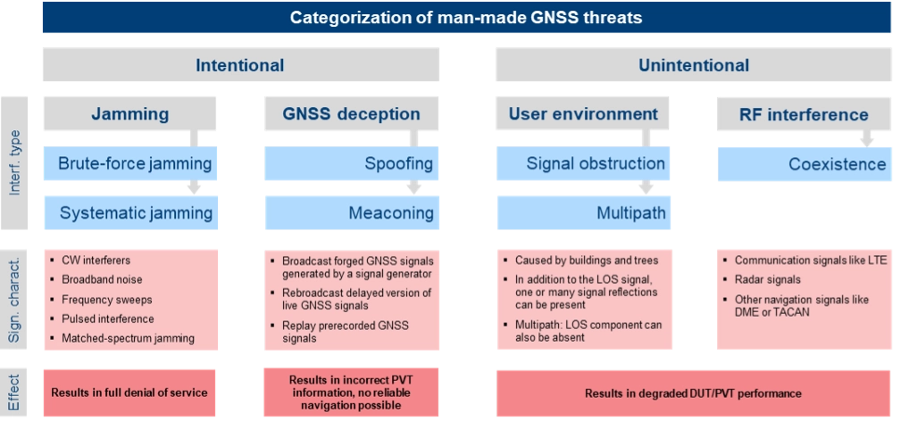
The most critical and common GNSS threats originate from interference signals that occur in the vicinity of a user receiver. Unlike system-inherent threats that originate from GNSS satellites or atmospheric conditions, these threats can be termed as “man-made” and categorized as shown in Figure 1.
Figure 1. Categorization of man-made GNSS threats. Credit: All figures provided by authors.
Jamming can be divided into two types of attacks. Brute-force jamming aims at completely blocking GNSS reception for a receiver by deliberately emitting interference signals like CW interferers, broadband noise or frequency sweeps with very high-power levels. As a result, the carrier-to-noise values will drop below the receiver’s acquisition and/or tracking threshold, and GNSS signals cannot be processed anymore. In contrast to such a simple jamming attack, where the attacker needs to have only basic knowledge about the GNSS signals (e.g. center frequencies and signal bandwidths), systematic jamming is a much more sophisticated attack, which can be further divided into
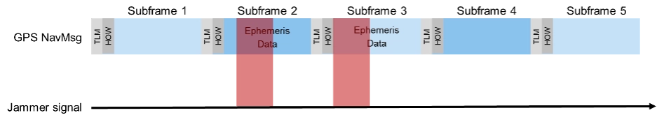
• Intelligent or smart jamming. The objective is to jam only a specific part of the navigation message (e.g. the ephemeris data section), so that the navigation message can never be fully decoded and the receiver will never be able to perform a position fix. All other parts of the navigation message remain unaffected, allowing signal tracking to continue for the receiver. Figure 2 illustrates this attack on the GPS L1 C/A signal.
Figure 2. An intelligent jamming attack performed on a GPS L1 C/A signal.
Smart jamming is much more complicated to implement for an attacker as the jammer must only be active during specific time intervals; this requires that the jammer is somehow synchronized with GNSS/Coordinated Universal Time. Moreover, the attack requires knowledge of the navigation message structure and what information the receiver needs to compute a position. Nevertheless, if done correctly, the attack is rather difficult to detect [1].
• Matched spectrum jamming. The objective is to generate a GNSS-like jammer signal with the same spectral characteristics as the real GNSS signals but without any valuable navigation information (i.e. the navigation message is missing). Matched-spectrum jamming is not straightforward, and to be effective, an attacker must replicate the GNSS signals for multiple visible satellites simultaneously, considering signal characteristics such as pseudo-random noise codes and, ideally, their correct Doppler shifts. In contrast to jamming, GNSS deception techniques aim to force the receiver to compute an incorrect PVT solution, compromising the integrity of GNSS-based navigation. The two basic methods are:
• Meaconing. This rather simple approach is based on rebroadcasting a delayed version of live GNSS signals. This can be realized by using a commercial GNSS repeater. Alternatively, previously recorded actual GNSS signals can be replayed.
• Spoofing. This includes generation and broadcast of forged GNSS signals. This is typically done using a GNSS simulator, but specialized, modified GNSS receivers combined with a transmitting unit can also be used. The simulated signals need to be self-consistent, i.e. a GNSS receiver must be able to compute a PVT solution based on the simulated constellation. Spoofing attacks can be rather simple, e.g. broadcasting high power signals that represent a different location than those of the receiver under attack. The aim is to force the receiver into a reacquisition process, tracking and processing only the fake GNSS signals. More sophisticated spoofing attacks are possible [2], but not discussed in this article.
Additionally, the PVT performance of a GNSS receiver can also be degraded by objects in the vicinity of a GNSS user, causing signal obstruction and reflections from buildings, trees, or the ground. Multipath can cause significant ranging and positioning errors. Multipath effects can hardly be avoided and must be seen as a permanent threat to GNSS signal quality.
Finally, other existing signals and services can interfere with GNSS, either because there is a frequency overlap (in-band interference) or harmonics from other signals fall into the GNSS bands (out-of-band interference). As an example, the upper part of the DME/TACAN band overlaps with a significant portion the GNSS L5 band. The effect of this type of interference on GNSS receiver performance can be analyzed by performing coexistence tests.
RX-Internal Detection and Mitigation Methods
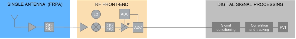
At least some of the threats discussed above can be detected and/or mitigated by the GNSS receiver. The capability of a GNSS receiver to detect and apply countermeasures to threats such as multipath, jamming or spoofing depends on the receiver’s availability of specific features and its basic architecture. Figure 3 shows the basic building blocks of a typical GNSS receiver with a single, fixed reception pattern antenna (FRPA).
Figure 3. Basic architecture of a FRPA receiver
The three basic building blocks are the antenna, the RF front-end and the digital signal processing section. The antenna is responsible for receiving the weak GNSS signals as well as for successive amplifying and band-limiting. It typically features a low noise amplifier (LNA) and a band-pass filter. The signals are then fed to the receiver front-end where the signals are amplified, down-converted to an intermediate frequency and converted to the digital domain. Part of this process is the automatic gain control (AGC) loop; the AGC acts as a variable amplifier, adjusting the power of the incoming signal and keep it constant over time. The sampled and quantized stream of IQ data is then fed to the digital signal processing section, where signal conditioning, acquisition and tracking, and PVT solution computations take place.
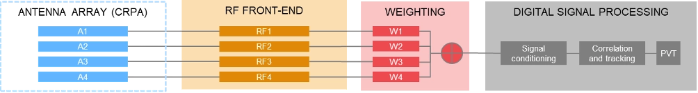
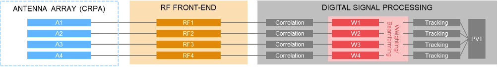
In contrast to using a single antenna with a fixed antenna pattern, some receivers use an adaptive antenna array, also referred to as controlled reception pattern antenna (CRPA). The idea is to weigh the signals received by each element according to dedicated optimization criteria. Typical optimization criteria are to minimize the signal’s output power towards a dedicated direction (“null-steering”), or to maximize the signal to interference or signal to noise ratio (“beamforming”). The underlying receiver architecture is more complex as signal weighting mechanisms must be added to the signal processing chain. These can be integrated before the digital processing block (“pre-correlation”) or implemented as an additional processing step between the correlation and tracking stages in the digital signal processing section (“post-correlation”). Both approaches are very effective in mitigating jamming and spoofing attacks, as they can either form a null in the direction of a strong jammer/spoofer or form beams towards the wanted signals from GNSS satellites, thereby de-weighting any unwanted signals coming from other directions.
Pre-correlation architecture of a 4-channel CRPA receiver
Post-correlation architecture of a 4-channel CRPA receiver
Within the processing chain of a GNSS receiver, there are different approaches and methods to detect and mitigate interfering signals, which are summarized in the following table:
AGC monitoring
●
●
Monitoring of the gain in the AGC loop. A sudden drop of the AGC gain can be an indication of an interfering signal; detection of high-power interferers; low-power spoofing attacks very difficult to detect
Spectrum monitoring
●
●
Detection of interferers and jammers above the noise floor; especially suited for detecting CW interferers. Not suited for the detection of matched-spectrum jammers, spoofers and meaconing attacks as their spectrum is typ. identical to the GNSS spectrum.
Frequency domain adaptive filtering
●
●
Dynamically identifies and suppresses unwanted frequency components (e.g., interference or multipath) by adjusting (notch) filter parameters.
Pulse blanking
●
●
Pulse blanking is a time-domain interference detection and mitigation technique used in GNSS receivers to detect and suppress short-duration, high-power pulses, typically caused by pulse jammers or Radar transmitters. Monitors the incoming signal power in short time windows and “ignores” this signal part in case certain power level thresholds are exceeded. Effective to mitigate pulsed jammers, not suited for multipath mitigation or anti-spoofing measures.
C/N0 monitoring
●
●
Monitoring over time and/or comparison against theoretical max. value; detection of all types of interferers; low-power spoofing attacks very difficult to detect
Time jump detection
●
●
Time jumps (backwards or forwards) are clear indications for meaconing or spoofing attacks.
PVT monitoring, incl. RAIM
●
●
Example: The computed position can be constantly compared against a known reference position. Not possible to distinguish between jamming/spoofing or other environmental effects like multipath. This also includes receiver-autonomous integrity monitoring (RAIM) schemes, that can be considered as a special form of PVT monitoring.
Doppler monitoring
●
●
Compare Doppler against theoretical/geometrical values; monitored Doppler profiles may show irregularities in case of an attack. Difficult to be separated from environmental or atmospheric effects.
CMC monitoring
●
●
„Code minus Carrier“ observable shows irregularities and increased noise in case of an attack. Difficult to be separated from environmental or atmospheric effects.
Signal Quality Monitoring (SQM)
●
●
Sampling of the correlation function using a few correlators; can detect distortions of the correlation function resulting from multipath, jamming or spoofing attacks.
Massive multi-correlator monitoring
●
●
Continuous, high resolution observation of the code/Doppler space. Can be done during signal acquisition and tracking. Can detect multipath, jamming, meaconing and spoofing attacks.
Derived Test Requirements
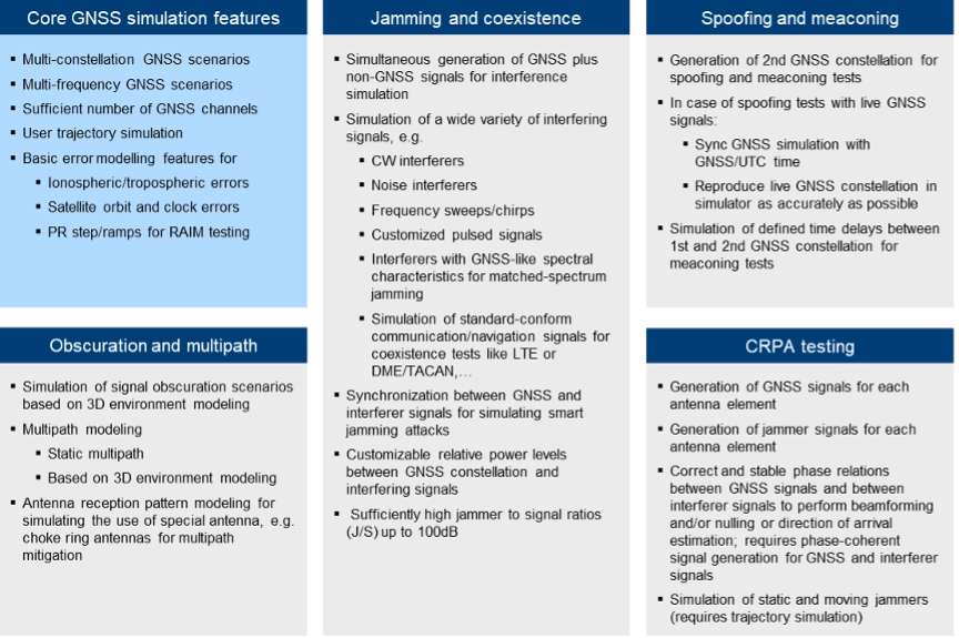
Based on the typical threat signal and attack characteristics, as well as the receiver-internal detection and mitigation methods discussed above, the test and simulation requirements listed in the table below can be derived. In addition to the requirements related to threat simulations (grey background), the table also contains “base requirements” for the simulation of realistic GNSS scenarios (blue background):
Testing: Methods, Setups and Challenges
The test methods, strategies and setups used depend on the architecture of the GNSS receiver being tested, the receiver features that need to be evaluated and the specific testing objectives.
A first categorization can be made by examining the origin of the GNSS signals being used for testing. The signals may come from real GNSS satellites and be used instantly and on-site (live GNSS testing) or recorded, stored, and played back in the lab (record/replay). Alternatively, testing can be done entirely in a lab environment using GNSS simulators. There are also hybrid test methods that will be discussed later in this article. In comparison to using real GNSS signals – either via live testing or the record/replay approach – using GNSS simulators in a lab environment offers significant benefits.
Simulation vs. Live GNSS Testing. One major drawback of using live signals is that the system conditions are often unknown at a given point in time, and – most importantly – they change over time. The locations of the satellites — and thus the geometric conditions — change as the satellites move along their orbits. Errors, such as atmospheric effects, are also time- and location-dependent. One of the most unpredictable error influences is multipath. The magnitude of multipath errors depends on a variety of different parameters, including the number of reflections, the distance between the reflection points and the antenna or the strength of the reflected signal. The latter is determined by the material properties of the reflecting surface. Both the geometric conditions and the material properties of the reflectors change or may change over time – the geometric conditions due to the permanent motion of the satellites and the reflector properties due to meteorological influences like rain, dew, or snow.
As a result, when using live signals, one must expect that the conditions change permanently and unpredictably and will never be the same for two distinct points in time. It is therefore very unlikely that two successive test runs can be performed under identical conditions. Repeatable testing, which is one of the most important test requirements, is impossible when using live GNSS signals.
Well-defined and controlled simulation conditions can only be ensured by using a GNSS simulator. A simulator typically offers fully customizable and repeatable scenarios (i.e., one and the same test scenario) that can be repeated as often as needed, producing the same signals with the same characteristics. Moreover, a simulator is often a more cost-effective and efficient solution, whereas using live signals would be time-consuming, complex, expensive or even impractical (e.g. test of airborne and spaceborne receivers).
The following discussion of typical test setups therefore focuses on the use of signal generators for GNSS testing. In terms of test scenarios, the focus will be on jamming, spoofing and coexistence testing. Testing against multipath influences is not specifically discussed below.
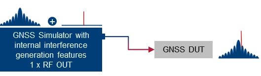
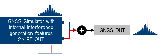
Basic simulator setups. The basic approach for testing against GNSS threats is to combine a “clean” reference GNSS simulation scenario with interfering signals and add the combined signals to the device under test (DUT). This basic concept can be implemented using two separate signal generators or an integrated solution that combines GNSS simulation and threat signal generation in a single instrument. Based on the architecture of the integrated solution (1 RF output vs. multiple RF outputs), GNSS and interfering signals are already combined internally, or GNSS and interfering signals can be fed to different RF outputs and combined with an external combiner before fed to the DUT.
Using two separate signal generators for GNSS threat testing. The interference generator (red) can either be a second GNSS simulator for generating spoofing signals or any other signal generator providing non-GNSS signals for jamming or coexistence tests.
Using a GNSS simulator with integrated interference generation capabilities. The signal generator features 1 RF outputs. GNSS and interfering signals are combined internally. An external combiner is not needed, but the dynamic range between GNSS and interferer (J/S) is usually limited.
Using a GNSS simulator with integrated interference generation capabilities. The signal generator features 2 RF outputs. GNSS and interfering signals fed to individual RF ports and combined externally. This requires an external combiner, but with the benefit that very high J/S ratios can be achieved.
Conducted testing vs. OTA testing. The basic setups introduced above only work if the receiver has dedicated and accessible input connectors to feed the antenna signal to the receiver’s front end. This is sometimes not the case, so that conducted testing is not possible and over-the-air (OTA) tests must be considered. A classic example of such DUTs is mobile phones, where no antenna connector is available, at least not without dismantling the device.
Testing such devices against interfering signals is still possible by using a shield box. The shield box has an RF input to feed in the combined GNSS and interfering signals. The signals are then retransmitted into the inside of the box and the DUT uses its integrated antenna to receive and process the signals coming from the GNSS simulator.
Using a GNSS simulator in combination with a shield box to test GNSS devices with integrated antennas.
OTA GNSS threat simulation using a shield box with 2 RF inputs and 2 transmit antennas. The GNSS signals and the interfering signals are fed separately (uncombined) into the shield box.
An alternative setup is to use a shield box with two RF inputs. In this case, the wanted signals and the interfering signals are not combined externally but are fed to the shield box via separate RF input connectors and transmitted to the GNSS DUT via separate transmit antennas.
Additional aspects and challenges must be considered when performing OTA tests using mobile phones as a GNSS DUT. This includes conducting a proper cold start, removing all preexisting navigation-related information from its memory, and disabling any other sensors that may contribute to computing the phone’s position, including any assisted GNSS services. This is typically not a concern for most standalone GNSS receivers that feature dedicated cold start procedures and usually have no other positioning sensors on board. On the other hand, initiating a real cold start for GNSS modules in mobile phones can be tricky. Just rebooting the phone does not necessarily work, and the availability of dedicated settings also depends on the phone’s operating system (e.g. iOS vs. Android).
Another challenge during OTA testing of mobile phones is how to assess and analyze the impact of any interfering signals on signal acquisition, tracking and positioning. This requires detailed analysis and monitoring features on the mobile phone, which are typically not a standard feature of the phone’s operating system. Specialized GNSS monitoring apps can be used instead. To get access to the data during the test, special screen mirroring apps can be installed on the mobile phone.
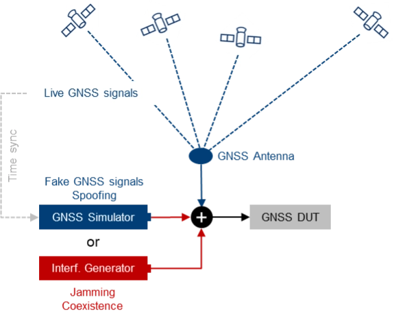
Testing with live signals. GNSS tests may also be performed in combination with live GNSS signals using already existing field infrastructure such as GNSS receivers installed at mobile base stations. A typical use case is to add one or several jamming/spoofing signals, or even an entire (stronger) “spoofing constellation” to an existing “live GNSS constellation” and test how the GNSS receiver reacts to such an attack. The typical test setup is illustrated in Figure 4.
Photo: Figure 4. The receiver’s response to interference is evaluated by introducing jamming or spoofing signals, alongside normal satellite signals using existing field infrastructure. This setup is often used to assess reactions to attacks.
This approach may be a good alternative to simulating everything with a GNSS simulator, as much more HW, i.e., more GNSS channels and more RF paths, are required with a simulator-internal approach. On the other hand, there are also some challenges associated with this test method, e.g., the signal generators, which need to be operated in a field environment. Moreover, for more sophisticated spoofing attacks, a prerequisite is the capability to time-synchronize the GNSS simulation with the live GNSS constellation.
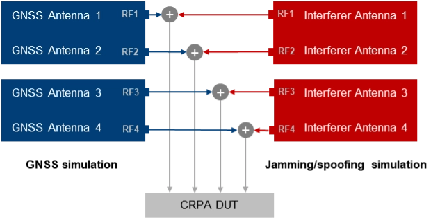
CRPA testing. For testing GNSS receivers with multiple antenna inputs, particularly CRPA systems, several RF sources/paths need to be combined and synchronized. The following illustration shows a possible setup for testing a 4-channel CRPA receiver against jamming or spoofing attacks. It is based on the 2-path architecture introduced above. It consists of two signal generators for generating GNSS signals for each antenna (left part of the setup) and two signal generators for generating the jammer/spoofer signals (right part of the setup). GNSS and interfering signals are combined per antenna element and fed to the RF inputs of the CRPA receiver under test.
For CRPA testing, generating phase-coherent signals is a must, i.e., it must be ensured that the phase relations between the GNSS signals and between the interfering signals represent the actual geometrical conditions and, above all, remain consistent throughout the simulation. To achieve this, a common LO signal needs to be used for generating the GNSS and interferer signals in all signal paths.
Another challenge is related to calibration. To correctly simulate the directions of the satellite signals and the interference signals, the test system must be calibrated at the RF interface to the DUT with respect to amplitude, phase and propagation time. This means that the amplitude, phase and propagation time differences between the individual RF paths, resulting for example from cables orRF components, must be compensated.
Rohde & Schwarz Solution
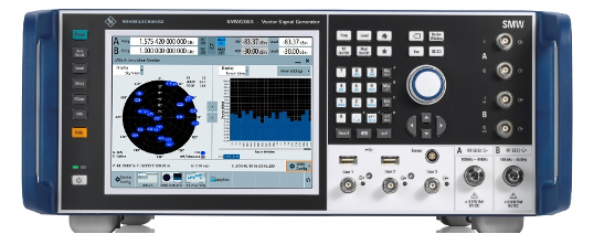
With GNSS test solutions from Rohde & Schwarz, all the relevant requirements for testing GNSS receivers against GNSS threats can be addressed. Available test solutions range from simple, single-channel, waveform-based signal generation with limited simulation time up to multi-frequency, multi-constellation GNSS simulators with 2 RF outputs, hundreds of GNSS channels and internal threat simulation capabilities, including non-GNSS signals for jamming and coexistence tests. For these advanced GNSS tests, the R&SSMW200A high-end vector signal generator is the ideal choice. It can be equipped with a multitude of GNSS options and feature sets.
Photo: Testing against GNSS threats with the R&S SMW200A
Jammer simulation. There are several ways to generate jamming and coexistence signals with Rohde & Schwarz signal generators in general and especially with the R&SSMW200A. Simple interference signals like noise or a CW interferer can be generated by using an optional integrated noise generator. For coexistence testing, the instrument can be equipped with signal generation capabilities for various standard-conforming communication signals, such as LTE. Customized interferer signals in the form of waveform files can be created by external software tools like MATLAB or Python and replayed by the instrument.
Customized jamming signal as well as entire jamming and coexistence scenarios can also be created using the R&SPulse Sequencer. The software allows to generate typical simple GNSS jamming signals like CW interferer, frequency sweeps, or pulsed interferers, but also complex jamming scenarios with consideration of moving interference sources and moving GNSS receivers, user-defined antenna patterns and scans. Depending on the signal characteristics, the jammer and receiver positions and the antenna arrangement, the software calculates the correct amplitude, phase angle and signal propagation times for the jamming signals.
Further reading
[1] Curran, James T. et. al. (2017): A look at the Threat of Systematic Jamming of GNSS, InsideGNSS, September/October 2017
[2] Dovis, Fabio et. al. (2015): GNSS Interference Threats and Countermeasures, GNSS Technology and Application Series, Artech House, 2015
Advanced Navigation is moving forward with plans to establish international positioning, navigation and timing (PNT) Centers of Excellence, with the UK location selection process currently underway.
The company is evaluating potential sites based on access to technical talent, logistics capabilities and proximity to major international airports. The final UK center location will be announced in late 2025, with additional global centers confirmed in early 2026.
Over the past year, Advanced Navigation has doubled its workforce and significantly expanded manufacturing capacity to address surging defense sector demand. The international COE network represents the next phase of the company’s growth strategy, positioning it to double its team again within 12 months.
“In an era of increasing complexity and contested environments, the ability to navigate with absolute certainty is becoming the world’s most critical strategic asset,” the company stated.
Building Supply Chain Resilience
To complement its Australian operations and establish robust onshore supply chains meeting local standards and security requirements, Advanced Navigation plans to partner with regional specialists in critical PNT sensing technologies, including:
Inertial sensing (optical gyroscopes and MEMS)
Vision-based sensing
Lidar and radar sensing
Acoustic Doppler velocity log sensing
The company emphasizes that navigation’s future depends on integrating diverse, adaptable sensor suites rather than relying on single technologies. Through its multi-sensor approach centered on inertial systems, the company aims to deliver resilience even in severe GPS-contested environments.
The expansion will accelerate innovation cycles, strengthen quality assurance and create opportunities for partners and research institutions across America and Europe to collaborate on breakthrough technologies.
Strengthening NATO Capabilities
The strategic expansion directly addresses NATO forces’ evolving operational needs. By establishing presence within U.S. and European industrial landscapes, Advanced Navigation aims to bolster critical infrastructure resilience while creating collaboration opportunities and jobs.
Beyond scaling production, the centers will focus on enabling seamless interoperability across NATO’s land, sea and air platforms, reducing integration time and costs for member nations. The COE network positions the company to power the next generation of autonomous systems and alternative PNT solutions worldwide.
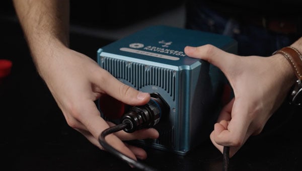
Advanced Navigation said the Boreas D90 FOG INS represents the type of technology that will be developed and manufactured at these new facilities.
UAV Navigation-Grupo Oesía has collaborated with Septentrio, a division of Hexagon, to enhance navigation resilience for unmanned aircraft systems. The partnership focuses on ensuring compatibility between UAV Navigation’s guidance, navigation and control systems and Septentrio’s GNSS receivers.
The collaboration integrates Septentrio’s high-precision real-time kinematic (RTK) capabilities with AIM+ anti-jamming and anti-spoofing technology. The anti-spoofing protection utilizes the Galileo Open Service Navigation Message Authentication (OSNMA) service alongside Septentrio’s proprietary algorithms to defend against signal interference and manipulation.
UAV Navigation’s flight control system now automatically detects when a Septentrio OSNMA-enabled receiver is connected and prioritizes its data within the navigation logic. This integration demonstrates the interoperability capabilities of the Spanish company’s systems while providing enhanced protection against GNSS jamming and spoofing threats.
Both companies seek to advance secure, reliable and high-precision navigation solutions for unmanned systems operating in challenging electromagnetic environments. The integration aims to maintain navigation accuracy and mission effectiveness when traditional GNSS signals face interference or manipulation.
Rohde & Schwarz has demonstrated its latest advancements in counter-drone technology at CUAS Expo 2025 at Thorney Island. The display featured an integrated system that included the ARDRONIS Wi-Fi detection solution and ARDRONIS Locate Advanced localization solution, along with the newly released ARDRONIS Effect configured as a multiband jammer.
At the event, Rohde & Schwarz showcased how its comprehensive counter-drone system detects, identifies and neutralizes rogue drones regardless of their operating frequency. The demonstration showed the system’s ability to manage non-cooperative and non-compliant devices operating outside established regulations.
ARDRONIS Effect in the Multiband Jammer configuration was a key highlight, demonstrating its unique wideband architecture which enables it to simultaneously jam multiple frequency bands, providing unparalleled protection against a diverse range of drone threats. Unlike traditional jamming solutions, ARDRONIS Effect in the Multiband Jammer configuration doesn’t rely on pre-defined frequencies, making it highly effective against drones operating on unconventional or rapidly changing frequencies.
ARDRONIS Locate Advanced complemented the jammer by providing precise drone detection and localization, allowing attendees to witness the system’s ability to quickly identify the location of drones and enable informed response decisions. The integrated system delivered a comprehensive view of situational awareness and robust protection capabilities.
Rohde & Schwarz said it received interest from attendees at CUAS Expo 2025 and had conversations about customer requirements. The company is following up with agencies and CUAS system integrators to discuss potential deployments of the ARDRONIS system.
“Discussions with attendees underscored the growing concern surrounding non-compliant drone activity and the need for adaptable, wideband solutions like ours,” said Christopher Mantle, business development manager for UK Land EW and Communications at Rohde & Schwarz.
GNSS spoofing has become a regular occurrence with the potential for severe consequences when precise and reliable positioning is critical. Legacy GNSS signals are the primary target for bad actors, as most precise positioning relies on these signals, and it’s constantly getting easier and cheaper for people to fake the message. To combat this, Trimble has introduced Trimble RTX-NMA (Navigation Message Authentication), the first solution on the market to mitigate spoofing attacks on the GPS and BeiDou satellite constellations. Trimble RTX-NMA leverages the Trimble RTX correction service and enhances the security and integrity of GNSS navigation messages for all Trimble ProPoint receivers. Used in conjunction with Galileo OSNMA, users now have three constellations protected from spoofing attacks.
Trimble RTX-NMA seeks to detect both fake GNSS signals and faulty ephemeris data through real-time authentication that ensures navigation messages from multiple RTX reference station receivers are genuine and trustworthy. It also encompasses faulty ephemeris detection, preventing unreliable data from being included in the correction stream. Enhanced security through advanced cryptographic techniques like AES encryption, and stream authentication, take it a step further. Trimble RTX-NMA is also compatible with various Trimble GNSS receivers using firmware version 6.40 or greater, making it a versatile solution for a wide range of applications without a subscription. With these features, Trimble RTX-NMA offers increased reliability, enhanced security, and improved integrity — an added layer of defense against potential threats such as spoofing.
As reliance on GNSS continues to grow, ensuring the security and integrity of navigation data becomes paramount. Trimble RTX-NMA represents a significant step forward in addressing these challenges, offering a robust and effective solution for enhancing GNSS security.
The Estonian news portal Delfi reports that a covert Russian military installation in the Królewiec region, just east of Poland’s border, is believed to be responsible for GPS interference affecting the Baltic states and the Gulf of Finland.
According to confidential sources, the facility’s primary mission is to monitor satellites and NATO communications, with the goal of undermining allied intelligence operations. Documents obtained by Delfi indicate that the base, located in Pioniersk, is part of Russia’s “Tobol” electronic warfare network.
The Tobol system is described as a network of surveillance, defense and command sites designed both to shield Russian satellite communications and navigation systems from NATO attacks and to disrupt NATO intelligence. The Królewiec facility, which focuses on satellite monitoring, was officially established in 2009 by the Russian Ministry of Defence. Similar installations are located across Russia, including near Moscow, Penza, Cheboksary and in Ulan-Ude, Siberia.
The Finnish newspaper Ilta-Sanomat, reports that Russia has been developing navigation jamming technology since the 1980s, initially as a counter to GPS-guided weapons. Those capabilities have since expanded in response to Western military equipment supplied to Ukraine.
Since the start of Russia’s full-scale invasion of Ukraine in 2022, incidents of GPS interference have increased in countries bordering Russia. Aviation and maritime navigation have been particularly affected, with pilots and ship crews reporting inaccurate or lost positioning data.
NAL Research, SGM Technology AS and Tschudi Shipping Company have formed a strategic collaboration to develop a new line of navigation and tracking products designed for the commercial shipping industry, using Iridium’s low-Earth orbit (LEO) satellite network.
This joint effort comes amid a rising need for reliable asset tracking and secure navigation tools in high-risk maritime regions, where threats to GNSS signals — such as jamming, spoofing and other forms of interference — are increasing on a global scale. Maritime authorities in some areas have reported a 350% increase in vessels affected by such disruptions in the past six months, according to NorthStandard. The technological interference has caused real-world consequences, including shipping collisions, operational delays, financial setbacks for global trade, and safety risks for crews at sea.
“As a fifth-generation shipping company, we’ve witnessed the evolution of maritime navigation, but never before have we faced technological threats such as GPS jamming and spoofing,” said Felix Tschudi, chairman of Tschudi Group. “These disruptions pose a serious risk to vessel safety, crew welfare, and the reliability of global trade routes. The industry must act collectively to address these vulnerabilities to protect maritime personnel and assets.”
The partnership’s initial focus is on integrating NAL Research’s decades-long expertise in assured positioning, navigation, and timing (APNT), tracking, and connectivity with the Iridium PNT service. This service provides a resilient, fully authenticated L-band signal engineered to withstand spoofing and jamming. The venture is also drawing upon SGM’s more than 15 years of experience in maritime technology and Tschudi Shipping Company’s international operations, bolstered by 140 years in commercial shipping and logistics. Together, their aim is to deliver high-reliability navigation solutions for environments where GNSS signals are compromised. Trials of the new solution are now underway.
“Protection against GPS vulnerabilities is no longer a nice-to-have, but a necessity to ensure operational success and asset safety,” said NAL Research President Robert Bills. “Through this collaborative effort, we are aiming to achieve complete global situational awareness and increase safety at sea for our commercial maritime customers, even in the most remote and challenging situations.”
“In today’s maritime landscape, the threat of GPS jamming and spoofing is no longer theoretical — it’s a growing reality. Ensuring navigational safety is critical, not just for protecting cargo and vessels, but for safeguarding the lives of seafarers who rely on precise and trustworthy systems every day,” said Steffen Grefsgård, CEO of SGM Technology AS.
As GNSS denial, jamming and spoofing threaten aviation safety, SandboxAQ and Acubed, the Silicon Valley innovation center for Airbus, have released real-world test results from a five-month, nationwide projectdesigned to test the accuracy of AQNav.
AQNav is an artificial intelligence-driven magnetic navigation (MagNav) system. AQNav uses advanced quantum magnometers to read Earth’s crustal magnetic anomalies, like a geoohysical fingerprint, then employs large quantitative models (LQMs) to filter out electromagnetic interference and precisely determine an aircraft’s position without relying on satellite signals.
These new results come from a nationwide initiative with Acubed’s Flight Lab to test the navigational accuracy of AQNav. Meeting the aviation industry’s Required Navigation Performance (RNP) standards is necessary for deploying the system on military, commercial and civilian aircraft.
AQNav’s performance was tested under various opertional scenarios and demonstrated advanced precision, accoding to SandboxAQ. The goal was to determine whether magnetic anomaly-aided navigation could broadly meet navigation requirements for commercial aircraft. AQNav’s capabilities exceeded the accuracy required for en route travel between airports — even on the program’s longest flight.
Accuracy
RNP Standard
Required Accuracy (meters)
% of Flight Time Met
RNP 0.3
550
64%
RNP 1
1,852
95%
RNP 2
3,704
100%
To demonstrate how the real-time capable system would operate in real-world conditions, flight data was collected, reprocessed, and streamed in real time to produce statistical insights, offering representative capability data for joint team evaluation.
Real-World Impact
SandboxAQ and Acubed focused on designing tests to mirror authentic, real-world aviation scenarios. For example:
Standard aircraft platform: AQNav was tested using publicly available magnetic maps aboard a standard Beechcraft Baron 58 – rather than a compensated geosurvey platform. This aircraft was modified only to accommodate the additional AQNav instrumentation – no extensive electromagnetic shielding or specialized noise isolation were used. All sensors were positioned inside the aircraft, powered by AQNav’s software to deliver a clean magnetic signal.
Use of apublicly available map. For all flights, AQNav researchers used the publicly available North American Magnetic Anomaly Map (NAMAM), which covers the U.S., Canada, parts of Mexico and surrounding oceanic regions.
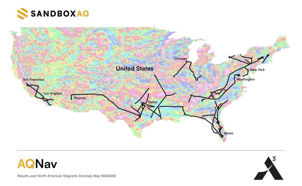
Unfiltered flight paths: Flight operations spanned diverse, operationally relevant routes between 200 airports across the entire continental U.S. (Fig. 1), without filtering based on magnetic anomaly strength, magnetic map quality, or favorable geomagnetic gradients. More than 150 hours of flight data was collected.
Diverse geophysical environments: Data was collected over a full range of conditions, from magnetically-rich mountains to sparsely featured plains, reflecting real-world geographies where aircraft might operate without GNSS.
True operational noise: Onboard, AQNav successfully filtered out the real-world interference generated by the aircraft, including electromagnetic, vibrational and other airframe-induced noise.
Fig. 1: Acubed Flights with AQNav (Credit: AQNav
Elijha Williams, AQNav’s technical engagement manager, said: “Our campaign was not about demonstrating proof of concept performance under ideal conditions, it was about proving AQNav’s viability under the noisy, messy, and unpredictable environments real pilots face every day.”
During test flights exceeding two hours, AQNav outperformed the Inertial Navigation System (INS) without GNSS 100% of the time. During a one-hour flight over the challenging mountainous and forested terrain of California, AQNav achieved its best-observed accuracy of less than 74 meters, or roughly two-thirds the length of an American football field.
Precision, Scale and Autonomy for the Future
This campaign marks a significant step toward widespread adoption of AQNav in aviation. By consistently maintaining accuracy in an uncontrolled, national testbed, SandboxAQ demonstrated AQNav’s operational robustness under real-world conditions.
Andrew Sosa Sosanya, a quantum navigation machine learning engineer at SandboxAQ, highlighted the impact of the data collected: “Thanks to Acubed, the U.S. Air Force, and other partners, we’ve accumulated a highly relevant MagNav dataset. This creates a flywheel effect—the more data we gather, the faster we can improve model accuracy across diverse mission profiles.”
AQNav is also undergoing testing with Boeing, a U.S.-allied air force, and as part of NATO’s 2025 DIANA cohort.
On June 13, following reports of Israeli airstrikes on Iran, interference rates in the Strait of Hormuz spiked. GPSJam.org, a service that tracks satellite signal interference, now reports medium-level disruption (between 2% and 10%) across the Gulf region. This is no isolated blip, but part of a pattern: electronic warfare is increasing in global hotspots. It’s also a warning.
Modern warfare is no longer about guns and bombs. Jamming, spoofing and using ever-more sophisticated cybertricks to disrupt GNSS are now regular tactics used to sow disorder. They are cheap, deniable, and often highly effective. But they also expose a dangerous weakness in how we navigate, communicate, and coordinate. If GPS is the backbone of global positioning, we are learning just how brittle it can be.
Strait of Hormuz Under Threat
The Strait of Hormuz is a narrow channel through which around one-fifth of the world’s oil passes, and here, ships are now at risk not only from pirates and mines, but from corrupted satellite signals. Spoofers can broadcast false GPS positions to nearby vessels. In recent years, we have seen ships appear to sail across runways, airports, and deserts, thanks to malicious signal interference. In aviation, spoofed or jammed GNSS signals have led to aircraft turning around mid-air or being diverted. These are real and growing threats.
As someone who has worked in naval intelligence and the defense industry for decades, I have seen how quickly technology evolves, and how slow we can be to protect our own systems. But there are solutions to the problem I’ve described. One is laser-based optical communications.
The Need for Resilient PNT
Laser communication is very difficult to jam or spoof. Unlike the low-power radio frequencies used by GPS, a laser beam is narrow, focused, and nearly impossible to intercept without being detected. And because lasercom is optical, not radio, it isn’t vulnerable to the same types of interference. That makes laser communication ideal for high-security communications and low latency support in contested environments.
Optical ground station networks, when paired with optical satellite links, also offer vastly higher data transfer capacity than conventional RF systems. Optical links can now carry 1,000 times more data than their RF counterparts. At a time when threats are growing quickly and data needs are exploding, that kind of capacity is essential.
This will make you wonder why lasercom isn’t more widely used. The answer is that only in recent years has it become mature and able to be deployed rapidly. Systems that once seemed exotic or experimental are now proven, reliable, and ready to scale. Many space agencies and defense organizations, including the US Department of Defense and NATO, are investing in them.
To be clear, optical comms will not replace GPS or radio. But they can supplement and support it, especially in high-risk areas where GNSS is under attack. Just as militaries don’t rely on one radar or one radio channel, governments shouldn’t rely on a single source of truth for navigation and timing.
Escalating Threats to Critical Infrastructure
When you depend on precise location data for everything from logistics to drone strikes to the safe passage of oil tankers, the idea that one bad actor with a spoofer can throw you off course is a real concern. When the threat can be made a reality without firing a shot, you can be sure it will be used more and more often.
Just as satellites offer a way to monitor subsea cable sabotage, they also offer a chance to future-proof our navigation and communication networks. The same technology that is being used to track ships and sense underwater disruptions can be adapted to create robust, high-speed, interference-proof backup channels. Governments that invest in this infrastructure now will be in a far stronger position to deter attacks, respond quickly, and maintain operational clarity when others cannot. We wish it were otherwise, but the world is becoming more dangerous, and attacks will accordingly become more common.
If the last year has taught us anything, it’s that infrastructure is no longer neutral. It’s considered a legitimate target, particularly by those whose aim is to create confusion and disorder. GNSS isn’t immune to this trend. In fact, because of it’s importance, it’s a prime target. We have to stop assuming that what worked in peacetime will work at a time of conflict. That, sadly, is the reality of this moment.
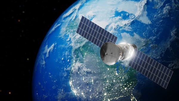
Xona Space Systems’ Pulsar-0 satellite, the company’s first production-class asset for a commercial navigation constellation, is now operational and undergoing in-orbit testing. Launched in March 2024 on SpaceX’s Transporter-10 mission, Pulsar-0 is designed to assess the performance of Xona’s Pulsar architecture, which aims to provide high-accuracy, resilient positioning, navigation and timing (PNT) services from low-Earth orbit (LEO).
According to Xona, Pulsar-0 is transmitting LEO-based PNT signals using a payload built to support signal authentication and increased resilience against interference — capabilities that have become more important as concerns about vulnerabilities in traditional GNSS systems grow. The system’s encrypted and authenticated signals are intended to mitigate risks from jamming and spoofing, and deliver stronger, more reliable service in environments where legacy GPS may be degraded.
Xona’s Pulsar constellation is being developed as a commercial complement to GNSS, offering centimeter-level accuracy and greater resistance to interference through modernized signal design and LEO deployment. The company reports that its initial signal waveforms are already being used by select government and commercial partners for prototyping and validation.
Pulsar-0’s technical objectives include:
High-precision GNSS corrections: Real-time correction data from LEO, targeting position accuracy within 10 cm.
Signal authentication: Cryptographically verifiable signals to reduce the risk of spoofing.
Jamming resistance: A signal strength up to 100 times greater than GPS, enhancing reliability in contested or congested radio frequency environments.
Stronger signals: Stronger signals designed to perform in obstructed locations, such as indoors or in dense urban areas.
The Pulsar-0 mission is primarily focused on validating Xona’s core technology and enabling live sky testing with early partners, paving the way for future launches and eventual commercial operations. The company aims to launch a constellation of hundreds of satellites to provide persistent, redundant PNT coverage for sectors including defense, logistics, mining and autonomous systems.
Further details on Pulsar-0’s performance are expected as data collection and testing continue throughout the year.
Thales, a European leader in resilient navigation, announced a €55 million ($63 million) investment to expand its industrial sites in Châtellerault and Valence, France. The investment, scheduled between 2025 and 2028, aims to address increasing demand for advanced navigation solutions in both civilian and military sectors and to reinforce the company’s sovereign industrial base.
The company is responding to rising threats such as GNSS jamming and spoofing by deploying a suite of resilient navigation technologies. These solutions combine precision, autonomy and security, which are critical for maintaining operational continuity in military missions and civil aviation. Thales integrates inertial navigation systems with GNSS signal reception, enabling reliable navigation even in contested environments. The TopAxyz inertial navigation system ensures autonomous capability, while the TopStar-M receiver and TopShield anti-jamming technology protect signal integrity. These advancements are supported by France’s Directorate General of Armaments under the OMEGA program for the modernization of GNSS equipment for the armed forces.
At the Châtellerault site, Thales plans to quadruple production capacity for inertial navigation systems by 2028. With six decades of expertise in laser gyroscopes, this facility is the only European supplier equipping civil aircraft and will expand its offerings for aircraft, land vehicles, ships and munitions. In Valence, mass production of TopStar-M receivers and TopShield systems is set to begin in 2026. The site will also introduce a new production line for inertial MEMS sensors, a technology that combines compact design with high performance, positioning Valence as a leader in France’s MEMS technology sector for defense. The launch will be accelerated with support from Tronics Microsystems for specialized industrial expertise.
Currently, more than 800 employees work at the two sites, with plans to hire 150 additional staff by 2028. The investment seeks to strengthen Thales’ regional presence and contribute to France’s position in the industry.