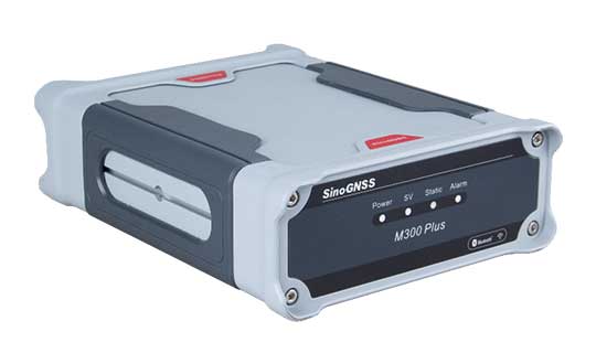
ComNav Technology has released the M300 Plus GNSS receiver to the international market.
The M300 Plus is designed to supplement the company’s M300 Pro, which is aimed at clients who need a more economical version for their CORS networks. The M300 Plus not only can be used as a CORS receiver, but is a good choice for monitoring projects and other applications.
With ComNav Technology’s new-generation GNSS engine, the M300 Plus can track all current and future constellations. By using a powerful, adaptive detecting and canceling technology, the M300Plus provides enhanced anti-jamming capability, which is critical for a reference station providing reliable GNSS data.
Photo: ComNav
The M300 Plus’ powerful built-in web server provides full remote control of the receiver configuration, status checking, firmware update and data download. It supports multiple independent data transfer through TCP/UDP/Ntrip protocol in RTCM, ComNav binary, NMEA and BINEX data formats, combined with Email Alert and FTP push, which improves the efficiency and profitability of businesses.
In addition to its standard Ethernet port for data transmitting, the M300 Plus GNSS receiver also fully implements a 4G module as an internet backup, which enhances the stability of data connections.
M300 Plus is now available through ComNav Technology authorized local distributors or ComNav Technology directly.
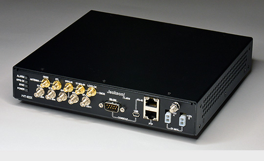
Jackson Labs Technologies (JTL) has launched the PNT-6220 Assured Reference — a product combining low-Earth-orbit (LEO) signals, GNSS, terrestrial, wireline and atomic clock services in one small solution, specifically designed for critical infrastructure applications.
The PNT-6220 reference seamlessly combines concurrent L1, L2, L3 and L5 GNSS reception with a custom JLT-designed LEO-based Satellite Time and Location (STL) timing receiver. It also includes terrestrial receivers and PTP/IEEE-1588 edge grandmaster (EGM) and PTP/IEEE-1588-slave capability.
The PNT-6220 provides assured PNT for critical infrastructure applications such as those described in the directives of Presidential Executive Order 13905.
It can serve as a timing reference for 5G equipment, an ePRTC-capable reference, or a high-performance disciplined reference that supports PTP/IEEE-1588, STL, RF distribution and multi-frequency GNSS capability.
The PNT-6220 will be able to select the most optimal UTC reference input automatically and auto-switchover among its numerous reference inputs if one or more of them are jammed or spoofed, as well as average several references for additional stability and accuracy.
If all external references are jammed, the unit can provide UTC timing from its internal holdover oscillator with options that have less than 100-ns drift over 24 hours. The unit is also capable of outputting a GPS RF distribution signal driven by the internal flywheel oscillator, which allows glue-less retrofitting of any GPS-based legacy user equipment to the state-of-the-art reference sources the PNT-6220 can receive by simply plugging into the legacy equipment GPS antenna input.
Available Options
Numerous options are available for the half-width 19-inch-wide rack-mount box.
GNSS Underground Coverage for Tunnels, Stations, Car Parks, Bus Stations and Airports in the U.K.
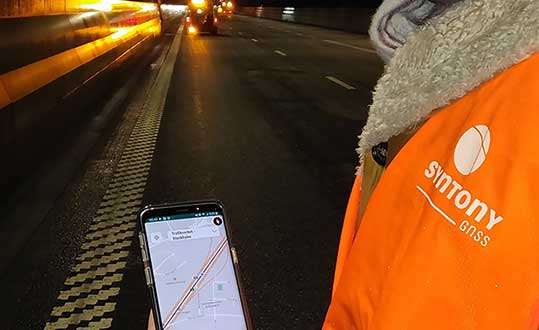
Syntony GNSS and Chronos Technology have formed a partnership to deliver underground GNSS positioning, navigation and timing (PNT) solutions for critical infrastructure applications in the United Kingdom.
Syntony GNSS is a leader and expert in the design and manufacture of GNSS systems, and Chronos Technology is a resilient GNSS system integrator.
GNSS coverage has become fundamental to many services from emergency services to asset tracking for example. Yet when entering an underground area such as a metro/subway, tunnel, car park, airport, or bus station for example, the GNSS signal is lost.
Syntony’s SubWAVE solution expands the GNSS coverage to underground areas, enabling the localization of any equipment with a standard GNSS chipset. Examples include standard smartphones and the TETRA Emergency Services Network handset used for security and services. Security and services applications include locating emergency calls, keeping track of staff, locating faults in tunnels, managing assets, locating trains and providing guidance.
A Syntony team member in a Swedish road tunnel during SubWAVE testing shows the positioning in an underground environment on a smartphone. (Photo: Syntony GNSS)
By emitting a perfect emulation of the “real” GNSS signal, SubWAVE offers underground operators, their staff, emergency services and the general public the benefit of full GNSS coverage in all underground areas for both operational and safety reasons.
One fundamental aspect is the user only needs a standard GNSS receiver (a smartphone or TETRA radio) — no new handsets, receivers or apps are required. The system operates by broadcasting synthetic location specific GNSS signals through existing or new leaky feeder cables in the tunnels.
Accuracy levels vary with leaky feeder and system complexity options; however, 2-meter accuracy is possible with a standard smartphone. The system is widely installed in the Stockholm metro and is in active trials throughout Europe and America.
“We are pleased to form a partnership with GNSS specialists Chronos,” said Joel Korsakissok, president of Syntony GNSS. “Their knowledge and experience, together with their dedicated installation, commissioning and support teams complement our sophisticated solutions.”
“Since its first general availability, one of the well-known shortcomings of the GPS system was lack of indoor or underground coverage,” said Charles Curry, managing director with Chronos. “Many have tried to solve this with various technologies over the years. Syntony’s innovative technology offers underground GNSS coverage for PNT applications. We are very excited by the possibilities and pleased to be partnering with them to offer their solution for critical infrastructure applications in the UK.”
In addition, Chronos will also supply Syntony’s sophisticated GNSS simulators used in the aerospace and defence industries for product testing.
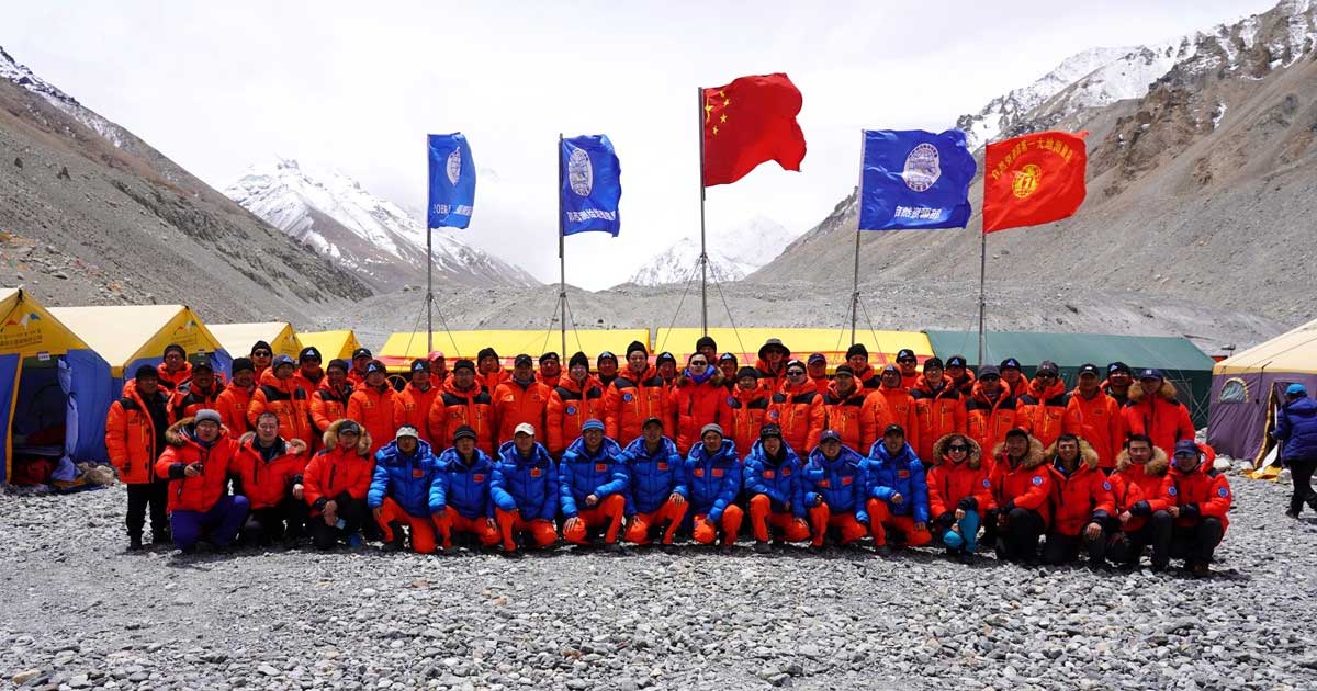
The survey team and sherpas reach the top of the world. (Photo: CHC Navigation)
China’s field work for new measurements of Mount Everest — the world’s, highest peak — are now complete. However, it will take two to three months for scientists to calculate and release its exact height, according to CHC Navigation, whose GNSS receiver was used.
The eight-member Chinese survey team reached the summit on May 27. The team erected a survey marker and installed a GNSS antenna on the snow-covered peak. The team also conducted a GNSS survey, snow depth measurement and gravity survey, said China’s Ministry of Natural Resources.
Scientists will use multiple traditional and modern measurement techniques to perform comprehensive calculations of the measurement data. After data analysis and processing, they will carry out theoretical studies and repeated verifications to determine the accurate height. Complex calculations are needed to eliminate errors caused by factors such as temperature, air pressure and the refractive environment.
CHC Navigation’s P5 geodetic GNSS receiver was successfully used by a Chinese team of surveyors to complete the 2020 Mount Everest Elevation Survey.
This is the first time that a team of Chinese surveyors has climbed the summit of Mount Everest, and it is also the first time that BeiDou-based Chinese GNSS receivers have been used to measure the height of Mount Everest, known in China as Mount Qomolangma.
China’s National Geodetic Survey Team and its Mountaineer’s Team used CHCNAV GNSS receivers. (Photo: CHC Navigation)
The Everest Project
To promote research on the Mount Everest elevation and to ensure the scientific character and accuracy of measurements, the Ministry of Natural Resources mobilized the Shaanxi Bureau of Topography and Geographic Information Mapping from the Chinese Academy of Topography and Mapping to plan and implement the measurements of the Mount Everest elevation. China’s National Geodetic Survey Team and its Mountaineer’s Team would undertake the arduous climb.
The plan set out the technical guidelines and required that the Everest Elevation Project be designed to achieve innovative and technological breakthroughs in several areas of research.
The first is to use the BeiDou satellite navigation system to perform GNSS measurements; the second is to use Chinese surveying and mapping equipment to complete the task.
Meeting Harsh Challenges
In October 2019, CHCNAV received a request from the Ministry of Natural Resources to provide GNSS equipment for the 2020 Everest Elevation Project. A dedicated team combining different departments, from R&D to manufacturing, was set up. The team elaborated the specific technical requirements from the National Survey engineers, in particular the difficulties and challenges related to the altitude of Everest.
Measuring the height of Mount Everest, especially the summit, is a challenge, not only for the limitation of the human body in such elevation environment, but also for the performance of the GNSS receiver itself.
At over 8,800 meters, the minimum temperature can reach -45°C and the atmospheric pressure is only 30 kPa (compared to the normal 101 kPa). All the surveying equipment used is exposed to both low temperature and low-pressure constraints.
In addition, the operation of the instruments must be as simple and reliable as possible in such an extreme environment. Surveyors wear thick winter clothing and lack oxygen, making every movement an extreme challenge. Finally, the measurement of the mountain peak must be completed at the first attempt, as re-measurement is impossible.
To meet these stringent requirements, CHCNAV has provided GNSS receivers that have passed the most rigorous environmental and reliability tests. The entire solution, from the GNSS receivers to the accessories, has been optimized to ensure mission success from the very beginning.
A wide temperature range of material — supporting an operating temperature range of –45°C to +85°C — were used, including redesigned lithium-ion batteries offering 12 hours of operation even at extremely low temperatures. Also used were antenna cables with a specific compound material to avoid any cracking or signal attenuation.
To ensure reliable operation of the receivers in a low-pressure environment, the GNSS receivers have built-in waterproof and breathable valves to maintain internal and external pressures. The low-pressure tests replicated a 25-kPa environment, corresponding to an altitude of 10,000 meters.
Additional ruggedized reinforcement prevented damage in the event of accidental receiver drop thanks to a robust design to keep the display and connectors safe. Following CHCNAV tests, third-party organizations were commissioned to perform environmental testing and reliability verification, including storage and operating at high/low temperatures, vibration, shock, rain, dust, humid heat, salt and fog.
From November 2019 to March 2020, CHCNAV’s GNSS equipment was supplied to the National Photoelectric Rangefinder Testing Center — under the requirements of the China Academy of Surveying and Mapping — for the most rigorous evaluation. As a result, the company’s GNSS receivers were selected to provide the peak altitude measurements of Everest in 2020.
The climb to the summit. (Photo: CHC Navigation)
Reaching the Summit
On April 5, 2020, at the Everest Elevation Survey Expedition Ceremony in Lhasa, CHCNAV officially donated GNSS equipment to the National Survey Team. Both product and technical training was provided to the team.
The 53 members of the first National Survey Team overcame the difficulties related to the environment, bad weather and the additional impact of COVID-19, and conducted a series of measurements on Mount Everest and surrounding areas such as level, gravity and GNSS.
Thirty of the 60 points of the GNSS control network were measured with CHCNAV GNSS receivers, including three of the seven Everest elevation intersection points.
On May 27, the CHCNAV GNSS receivers finally reached the summit and successfully completed the task.
The successful achievement of the Everest elevation measurement reflects the performance of the Chinese surveying and mapping industry, confirms BeiDou as a major part of the GNSS systems, and demonstrates the technical success of CHCNAV as a major player in the GNSS industry.
About CHC Navigation
Founded in 2003, CHC Navigation is a publicly listed company creating innovative GNSS navigation and positioning solutions. With a global presence across the world, distributors in more than 100 countries, and more than 1,300 employees, CHC Navigation is today recognized as one of the fastest-growing company in geomatics technologies.
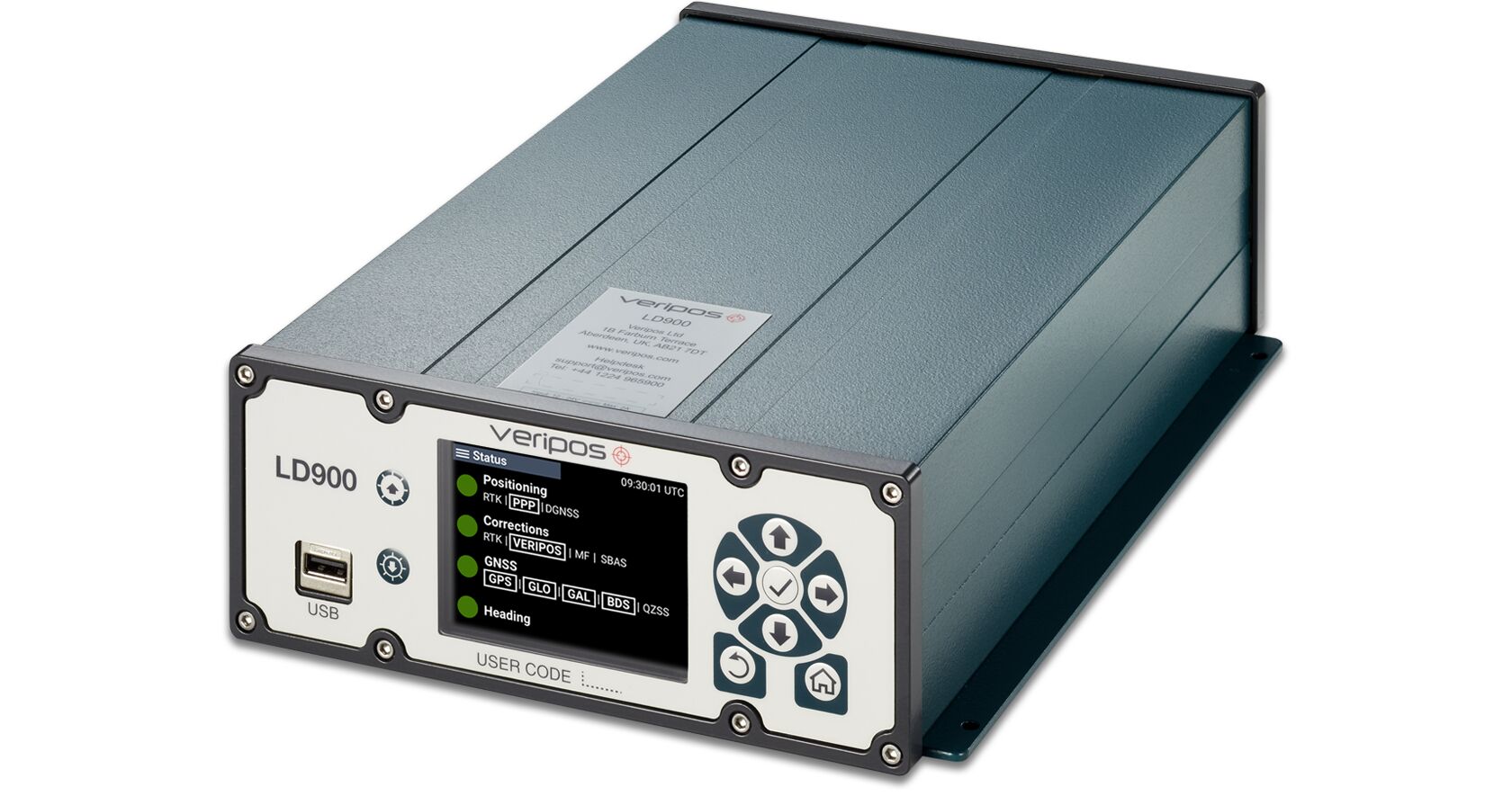
Veripos has released the LD900, a quad-band GNSS receiver capable of tracking GPS, GLONASS, BeiDou, Galileo and QZSS constellations to provide reliable and accurate positioning. Access to multiple GNSS signals allow for better satellite availability and reduce the impact of satellite masking or blockage, which can affect positioning.
LD900 also receives L-band signals on multiple channels, providing access to the worldwide independent correction links and services provided by Veripos. With correction data available simultaneously from up to three correction satellites, the impact of satellite masking can be minimized to ensure reliable reception of correction data. Using the independent L-band RF input on the LD900 allows the connection of a dedicated L-band antenna ensuring optimal reception of correction services, especially at high latitudes, the company said.
Veripos provides accurate and reliable positioning for all marine applications via their redundant positioning and multi-frequency precise point positioning (PPP) Apex and Ultra services.
The Apex5 correction service utilizes all GNSS constellations delivering 5cm positioning accuracy for use in the most demanding offshore applications. Real-time kinematic (RTK) corrections can be utilized by the LD900 for applications where this service is required.
The intuitive color display and navigation menu makes setup, configuration and system status monitoring simple. The display also helps troubleshoot issues with the LD900 allowing faults to be quickly diagnosed and resolved. The LD900 can also be configured remotely through the Veripos Quantum software.
Features and Benefits
Supports decimeter-level multi-constellation positioning with Veripos Apex and Ultra PPP correction services
Multi-channel L-band allows simultaneous tracking of 3 Veripos correction service satellites
Independent L-band RF input
Easy-to-use, intuitive, color display for simple configuration and monitoring
Advanced signal filtering mitigates the effects of interference from other transmitters
Optional ALIGN GNSS heading solution
Optional MSK Beacon receives corrections from IALA marine radio beacon network
Automatic 72-hour rolling data log for incident support
With the first GPS Block III satellite SVN 74 being set as healthy and active in January, GPS has reached another important milestone. Setting the vehicle healthy and active makes the satellite available for use by military and civilian GPS users around the world. GPS has been a hugely successful system, consistently exceeding its performance specification and providing users with levels of accuracy and availability that would have seemed astonishing only a few short years ago.
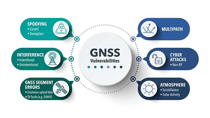
Despite these successes, the limitations of GPS and other GNSS have been highlighted by a catalog of real-world well-documented jamming and spoofing incidents, some of which have had serious impacts. With this increase of incidents, the military and commercial worlds have become increasingly aware of the vulnerabilities of sole reliance on GNSS. Interference with GNSS is a critical risk to not only business continuity, but to the safety of the world.
Image: Spirent Federal
Simply trusting the output from a GNSS receiver without question is no longer acceptable in safety- or liability-critical applications. The focus of many manufacturers and developers has been on assuring the integrity of reported GNSS PNT data.
Recently, more systems have begun using non-GNSS data sources to augment the GNSS solution. A GNSS receiver becomes one of the many sensors used in a system that combines their inputs to provide an assured, trustworthy source of precise positioning and timing data even when GNSS is disrupted. There are also active global initiatives in both commercial and military domains worldwide to seek and develop direct replacements for GNSS-based navigation and timing systems.These systems eliminate the use of GNSS completely and are termed “alternative navigation systems.”
Whether assured, augmented or alternative, these PNT systems need careful assessment. Their performance, robustness and resilience need to be measured in normal conditions and with interference.
Spirent is actively working to develop new, relevant test frameworks and designing the next generation of PNT test equipment that can easily integrate with and assess more than one technology. From inertial integrated with GPS to a number of alternative PNT systems that are being analyzed by the U.S. government, Spirent is working to unlock the maximum benefits of the next generation of PNT solutions.
Roger Hart, director of engineering, joined Spirent Federal in 2015. He has worked in development of spacecraft navigation systems, including GPS, for civil, NASA and defense applications since 1986. Guy Buesnel is Spirent’s specialist PNT Security Technologist covering the areas of PNT threats and mitigation.
This insight column from Septentrio explains the role of GNSS corrections in precise positioning. It explores the three most popular correction methods: RTK, PPP and PPP-RTK.
Let’s say you need reliable accurate global positioning in your technology. You do some research and decide to get yourself a multi-frequency GPS/GNSS receiver. You order an evaluation kit, but how to get your receiver to deliver the high accuracy that it promises?
GNSS receivers rely on external corrections to compensate for GNSS errors to achieve decimeter- or centimeter-level accuracy as fast as possible.
Correcting GNSS errors
GNSS-based positioning is calculated using a method that, by itself, is limited in accuracy due to several errors caused by GNSS satellites as well as the Earth’s atmosphere.
Even the advanced clocks on board GNSS satellites experience minute drifts that cause clock errors.
The movement of GNSS satellites is predicted as they orbit the Earth. These predictions are not perfect, which results in orbit errors.
Satellite equipment introduces small signal errors, which are modeled as satellite biases.
Atmospheric errors caused by distortions and delays are experienced by the signal as it passes through the Earth’s ionosphere (outer layer) and troposphere (layer near the Earth’s surface).
The local environment around the receiver as well as the receiver itself can introduce errors. For example, satellite signals can be reflected off buildings and tall structures (multipath).
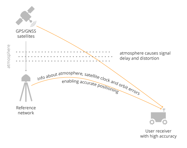
A GNSS receiver cannot correct satellite and atmospheric errors by itself; it relies on data provided by an external source. Clock and orbit errors are satellite-dependent, and so are the same around the world. Atmospheric errors, on the other hand, depend on the path the signal takes as it travels from the satellites to the user, differing depending on the receiver’s location.
To overcome both satellite and atmospheric errors, a reference station (also known as a base station) can be used. A reference station — a GNSS receiver installed at a fixed and precisely known location — estimates GNSS errors and sends them in the form of GNSS corrections to the user receiver. A reference network consists of interconnected reference receivers spread over a geographic area.
A user receiver gets data sent from a GNSS reference station to correct satellite and atmospheric errors. (Image: Septentrio)
Receiver-side errors can only be handled partially, by robust receiver technology and careful operation. Depending on which type of corrections are applied, it can take a few seconds to several minutes of initialization time for high accuracy to be achieved.
Types of corrections for high-accuracy positioning
Until recent years, RTK and PPP have been the established methods of providing GNSS corrections to user receivers. But the demand for high-accuracy positioning is on the rise, paving the way for new positioning techniques such as the hybrid PPP-RTK.
RTK: Highest level of accuracy. With the RTK (real-time kinematic) method, a user receiver gets correction data from a single base station or a local reference network. It then uses this data to eliminate most of the GNSS errors.
RTK is based on the principle that the base station and the user receiver are located close together (a maximum 40 kilometers or 25 miles apart) and therefore “see” the same errors. For example, since the ionospheric delays are similar for both the user and the reference station, they can be cancelled out of the solution, allowing higher accuracy.
While in the RTK method corrections are provided for a specific location, in the PPP and PPP-RTK methods, a correction model is broadcast to a larger area, but with slightly lower accuracy. To transmit this correction model, a message format called SSR (Space State Representation) can be used. There is some confusion in the industry about the term “SSR” since it is often associated with the newer PPP-RTK method. But be careful, since “SSR” is occasionally used as a buzzword to refer to traditional PPP services as well.
PPP: Globally accessible and accurate, but at a cost. Precise point positioning (PPP) corrections contain only the satellite clock and orbit errors. Since these errors are satellite specific, and thus independent of the user’s location, only a limited number of reference stations is needed around the world. Because atmospheric errors are not included in PPP corrections, only a lower accuracy level can be achieved with this method. Also, a longer initialization time is expected of up to 20-30 minutes, which may not be practical for some applications. PPP has been traditionally used in the maritime industry; today it has expanded to various land applications such as agriculture as a convenient way to get global GNSS corrections.
PPP-RTK: Best of both worlds? PPP-RTK (a.k.a. SSR) is the latest generation of GNSS correction services, combining near-RTK accuracy and quick initialization times with the broadcast nature of PPP. A reference network, with stations about every 150 kilometers (100 miles), collects GNSS data and calculates both satellite and atmospheric correction models.
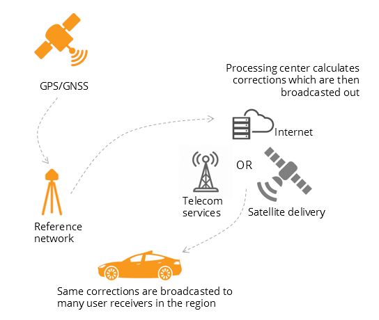
As explained above, atmospheric corrections are regional, and so a denser reference network is needed than for PPP. These corrections are then broadcast to subscribers in the area via internet, satellite or telecom services. Subscribed receivers use the broadcast correction model to deduce their location-specific corrections, resulting in sub-decimeter accuracy.
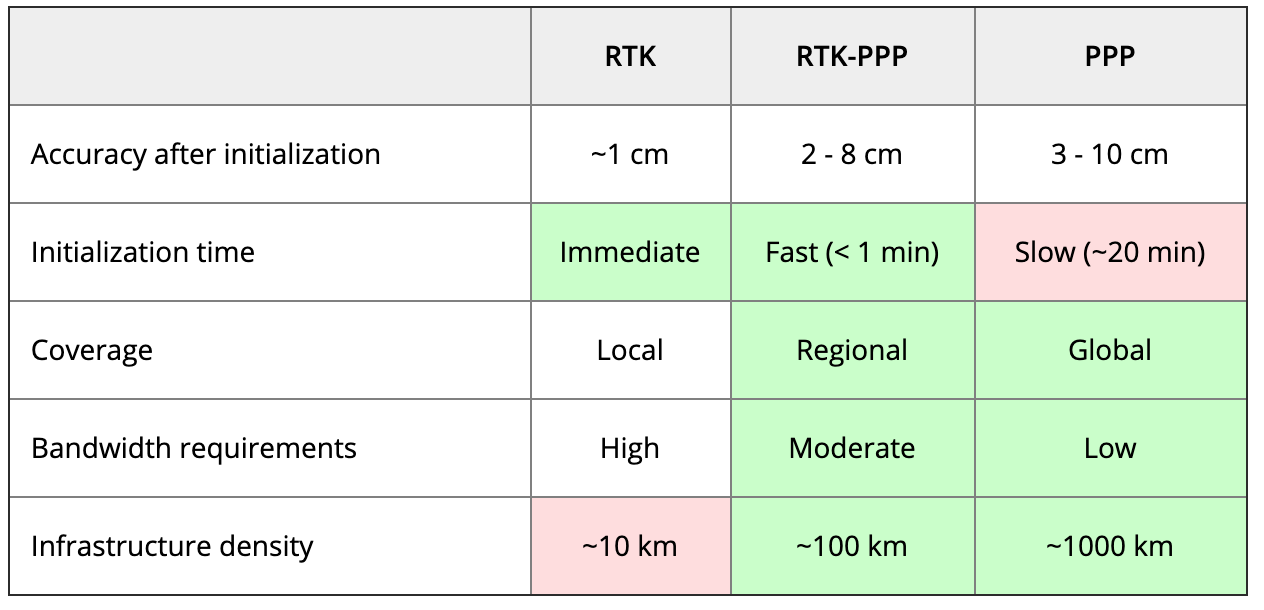
Comparing the three GNSS correction methods
The table below compares the three correction methods, highlighting their strengths and weaknesses.
Table: Septentrio
The infrastructure density and initialization time for all three methods vary with the different kinds of errors that are corrected. The broadcast nature of PPP-RTK and PPP, as well as the lighter infrastructure that they require, makes these methods scalable for mass-market applications.
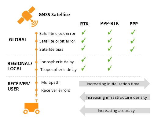
Types of errors that are corrected by each of the three methods. (Image: Septentrio)
Some GNSS receivers also incorporate advanced positioning algorithms to compensate for receiver-side issues such as multipath (for example, see Septentrio APME+), jamming and spoofing. This adds reliability and robustness to high-accuracy positioning.
Getting GNSS corrections
Modern industrial receivers often get their GNSS corrections via a subscription service, delivered via internet (using NTRIP protocol), satellite or 4G/5G. Today, there is a boom in the correction-service market driven by high-accuracy demands of the automotive industry, automation and smart consumer devices. Automotive suppliers and many other new players are deploying infrastructure to set up services for centimeter-level positioning around the globe.
User receivers often get their GNSS corrections via a subscription service delivered via internet, satellite or 4G/5G. (Image: Septentrio)
PPP and PPP-RTK corrections can even be transmitted directly by the GNSS satellites, as in the Japanese CLAS service from the QZSS constellation, or in the planned High-Accuracy Service (HAS) from Galileo. Depending on the network density and quality of the error modeling, different initialization times and accuracies can be achieved. This means that positioning quality can vary from one service provider to another.
Major telecom companies such as Deutsche Telekom as well as the Japanese Softbank and NTT are equipping their infrastructure with GNSS receivers to enable new corrections services. 3GPP, which provides specifications for mobile telephony including LTE, 4G and 5G, now covers broadcasting of GNSS satellite corrections in its mobile protocol. Since reference receivers are becoming part of critical infrastructure, such as telecom towers, it is essential that they have a high level of security to protect them from potential jamming or spoofing attacks (for example, Septentrio AIM+ technology).
Which corrections are right for me?
The right correction service for your technology will depend on your location and service area, your accuracy and reliability needs, as well as your budget. Because the corrections market keeps expanding, it is now more important than ever that integrators or GNSS manufacturers assist you in selecting the best correction method for your industrial application.
If you choose a GNSS receiver which does not “lock” you to a certain correction service, you will be free to choose a correction method which is most suitable for your application and its location. Such “non-locking” open-interface receivers also offer customers flexibility to switch to another more beneficial service in the future, as correction methods keep evolving.
Regulus Cyber, creator of what it calls “anti-virus” software to protect GPS navigation and timing across a wide range of applications, is collaborating with Harman, a connected-car company.
The software-based cybersecurity solution will be part of Harman Shield, the company’s risk-management offering for vehicle manufacturers and mobility companies.
“We are looking forward to joining forces with Harman, a Tier 1 supplier to the automotive industry, a trusted partner to more than 50 global vehicle manufacturers. Coming together with Harman is a great testament to the necessity of GPS protection measures in our industry,” said Yonatan Zur, CEO of Regulus Cyber.
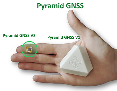
“We’re seeing our OEM customers expand into the digital and mobility spaces, offering added-value services to consumers by leveraging connectivity and mobile applications,” said Asaf Atzmon, vice president and general manager, Automotive Cybersecurity at Harman. “Through Harman Shield, we offer full visibility, analytics and risk management capabilities into cyber threats, and Regulus Pyramid GNSS solution complements our offering with another layer of protection against GPS hacking. We’re excited about the possibilities of this new collaboration with Regulus.”
The Regulus Pyramid GNSS is a software solution that uses machine learning to detect spoofing and defend any GNSS receiver, device or chipset against it — ensuring the security and reliability that are essential to safe and accurate navigation. GPS spoofing attacks are becoming more common and are often difficult to detect and protect against.
Pyramid GNSS uses a combination of patented algorithms, developed over years of spoofing experiments to protect against attacks at the firmware, operating system, or application level. This deal is further proof of the market demand for resilient navigation and positioning at a time when GPS hacking is a growing concern.
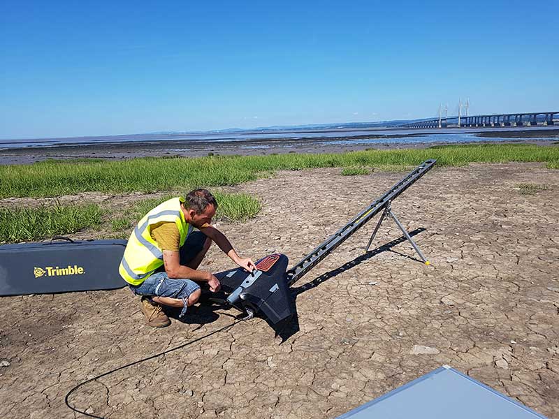
Prepping for flight: Andreas Garbe, AgSurvey, sets up the UX5 HP for a topographic survey at Severn Beach, a village in South Gloucestershire. (Photo: Trimble)
Based in Bristol, AG Surveys has been collecting topographic beach surveys around the country as part of England’s Environment Agency’s coastal monitoring campaign.
In the first integrated approach of its kind in the program, AG Surveys uses the Trimble UX5 unmanned aerial system (UAS) equipped with a Trimble/Applanix GNSS receiver along with photogrammetry software. The UAS-based system has not only confirmed its viability for coastal monitoring, it has been bringing new business opportunities ashore since 2017.
For each beach, AG Surveys must provide one baseline survey based on a 5-meter grid with a height accuracy of 3 centimeters. Also required is a series of profile line surveys. Profile surveys follow pre-defined lines set every 50 meters from the back of the beach to the low tide line, with GNSS measurements taken within 10 centimeters of each side of the line.
Crews typically cover 3 square kilometers a day, flying four to five Delair drone flights at an altitude between 100–120 meters, at speeds of 80 kph and a lateral overlap of 80%. To ensure the reliability and accuracy of the UAS data, they use a minimum of 10 ground control points (GCPs) for each flight block and measure each target’s position with a GNSS receiver.
Once flights are complete, the team imports into Trimble Business Center (TBC) the flight and GNSS data and the base station survey data. Using both on-board GNSS positioning data and the ground control data, they process precise, short baselines between the base station and each photo point. All images are then integrated into Trimble’s Inpho UASMaster software to create a dense point cloud and a seamless orthophoto of the entire area of interest. (UASMaster is now integrated into the TBC Aerial Photogrammetry Module). If needed, they can also use UASMaster to produce a seamless, georeferenced orthophoto directly from the point cloud.
The mysterious and fascinating Kame of Isbister is situated in Shetland’s north mainland near the North Roe. The location has been studied several times, including by the Extreme Archaeology TV series in 2003. The uninhabited grassland continues to attract explorers because of a series of secret structures.
Those structures are hidden on the sea-faced slope and can’t be seen from the land nearby. One theory posits that it’s an eremitical monastery settlement. The late Pictish/early Medieval site is hard to access — and that’s where drones coupled with GNSS receivers helped explorers.
Because the site is hard to access, the team decided to use the DJI Phantom 4 RTK SUA (drone and base) with two flights. One flight captured both the Kame and a piece of the mainland for context, with a ground sample distance (GSD) of 2.4 centimeters/pixel (cm/px). The second flight was on a shorter GSD of 1.9 cm/px to capture detailed pictures of the cape and structures.
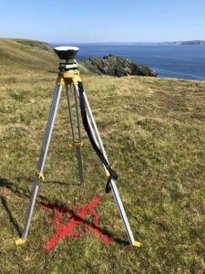
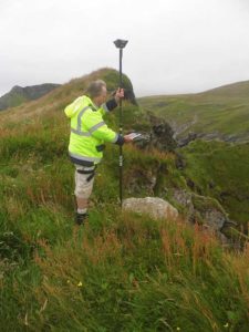
Before the survey, the team used the Emlid Reach RS+ real-time kinematic (RTK) receiver to identify and establish the base mark for the drone on the mainland nearby.
Photo: Emlid
The Reach RS+ collects ground control points. (Photo: Emlid)
Ground control point locations. (Image: Emlid)
The base mark was then post-processed using data from the OS Net reference station in Lerwick. Considering the long baseline (52 kilometers), it took the team four hours to observe the mark with Reach RS+. Later, when the archaeologists managed to climb the headland, the RTK receiver collected several noticeable control points.
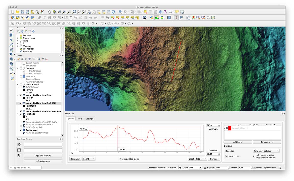
Creating the 3D model. During both flights, the drone’s base was sending corrections in RTK mode. In post-processing, horizontal accuracy of the processed map initially was within 10 cm with vertical at 15 cm. After adding the control points gathered with the RTK receiver, the error was reduced to 6.5 cm, significantly increasing the accuracy of the model.
The team performed the GIS processing in QGIS 3.4 LTR.
Screenshot: Emlid
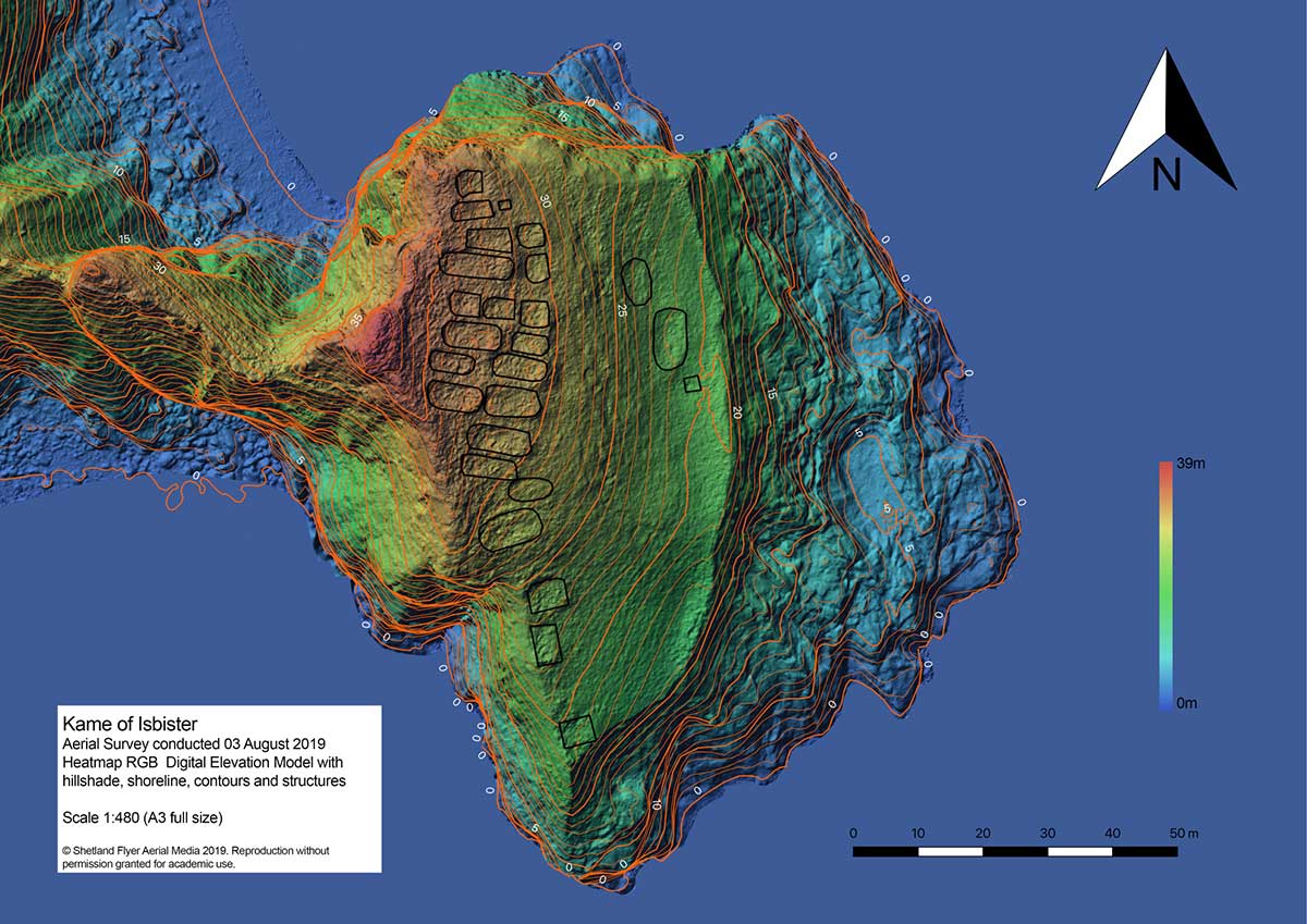
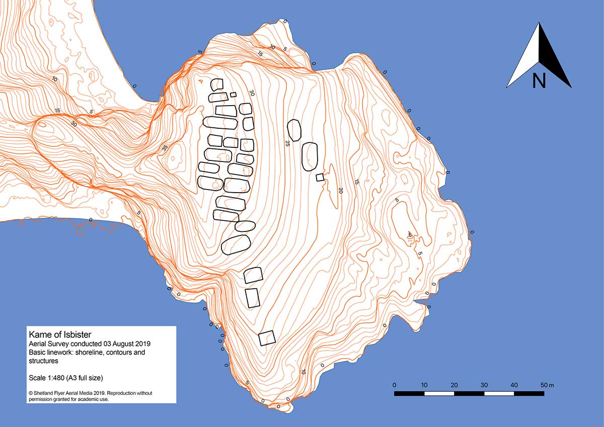
Despite the long grass, they managed to distinguish each structure out of the orthomosaic using the 32-bit floating point raster digital elevation model (DEM). The team created a basic map with structures and contours, a hillshade version and a heat map.
With proper preparation and setup, a GNSS RTK receiver with a drone can gather enough high-accuracy data to create accurate models and maps of an archaeological site — even if it’s hard to reach.
Shoreline contours and structures. (Image: Emlid)Shoreline contours and structures with hillshade. (Image: Emlid)3D model: The heatmap of the Kame of Isbister shows elevations and the archaeological site. (Image: Emlid)
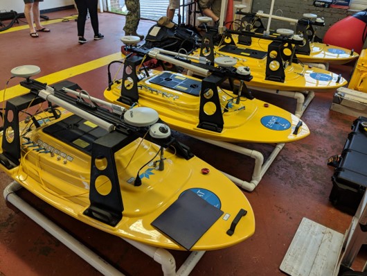
Teledyne Marine has released the Z-Boat 1800-T unmanned survey vessel, equipped with Trimble’s high-precision GNSS heading receiver and compatible with Trimble Marine Construction (TMC) software.
The Z-Boat 1800-T enables marine construction and dredging projects to run efficiently and be monitored in real time anywhere in the world.
The Z-Boat 1800-T, designed and manufactured by Teledyne Oceanscience, is a high-resolution shallow water hydrographic unmanned survey vehicle with the newly released Odom Hydrographic Echotrac E20 Singlebeam Echosounder and dual antenna Trimble BX992 GNSS heading receiver. Each sensor is integrated into a compact, portable and cost-effective package.
The combination of Trimble’s high-precision heading and positioning/guidance paired with Teledyne’s accurate/precise sonars allow for data collection under harsh conditions. Both sensors can be removed and mounted on other watercraft and barges to maximize data-collection capabilities.
The data is remotely viewable in real time, giving the operator full control and confidence. The boat’s small footprint allows access to areas that are too small, confined or unsafe for larger vessels.
Photo: Teledyne Marine
“Teledyne Marine and Trimble continue to create a paradigm shift for marine construction by providing real-time vision, guidance and survey across a project’s complete construction lifecycle — improving safety, eliminating or reducing work redoes, and helping to complete projects faster and under budget. This system provides as-building updates or what we call ‘eyes below the water,’” said Ted Germann, Teledyne Marine’s vice president of Emerging Markets.
“Trimble’s experience in GNSS guidance systems, and Teledyne’s leadership in shallow-water hydrographic surveying provides an ideal solution for marine construction contractors and surveyors,” said Kevin Garcia, general manager of Trimble Civil Specialty Solutions. “The Teledyne Z-Boat 1800T release means that near-shore construction workflows now have a quick mobilization tool to identify sub-surface obstructions, provide ad hoc inspections and increase site safety. This feature-loaded solution makes the unmanned surveying vessel affordable for all sizes of customers.”