Hexagon has successfully completed acquisition of Inertial Sense, strengthening its assured positioning, navigation, and timing (PNT) portfolio with tactical-grade GNSS+INS technology.
The acquisition reinforces Hexagon’s long-term commitment to innovation in high-performance navigation technologies. Inertial Sense strengthens Hexagon’s positioning portfolio and further enhances its assured PNT capabilities.
Headquartered in Provo, Utah, Inertial Sense will continue supplying inertial navigation solutions and will be integrated into Hexagon’s Aerospace & Defence Division.
“Inertial Sense brings exceptional GNSS+INS innovation that advances our assured PNT roadmap and expands resilient positioning capabilities in GPS-challenged environments,” said Stig Pedersen, president, Aerospace & Defence Division, Hexagon. “Their compact, cost-effective solutions meaningfully enhance our ability to serve aerospace and defence applications.”
Inertial Sense is a provider of high-performance navigation solutions, with more than 30,000 inertial systems deployed worldwide across defense and commercial applications.
Inertial Sense was founded in 2013 by Walt Johnson, who started Inertial Sense 10 years ago to make precision navigation lightweight and affordable so that it could be deployed anywhere and accessible to any business. This includes the rapidly emerging industries of drones, mobile robotics, aerospace and defense, autonomous vehicles, and automated manufacturing, all of which would require scalable and affordable navigation solutions.
Quantum technologies may offer a solution to GPS jamming and spoofing, according to the University of Chicago. Already, prototypes are being tested of a suite of sensor-based techniques that do not rely on satellite signals.
GPS jamming and spoofing have emerged as growing threats in recent years, according to the Chicago Quantum Exchange, based at the university. In 2024 alone, more than 1,000 commercial flights per day were affected by GPS spoofing, especially while flying through regions like the Middle East and Eastern Europe.
During these incidents, in-flight instruments show pilots that their aircraft is flying higher or lower than they truly are or that they are miles off their actual location. In maritime settings, spoofed GPS signals have even caused ships to veer off course or run aground. These are not isolated glitches but the result of deliberate electronic warfare tactics.
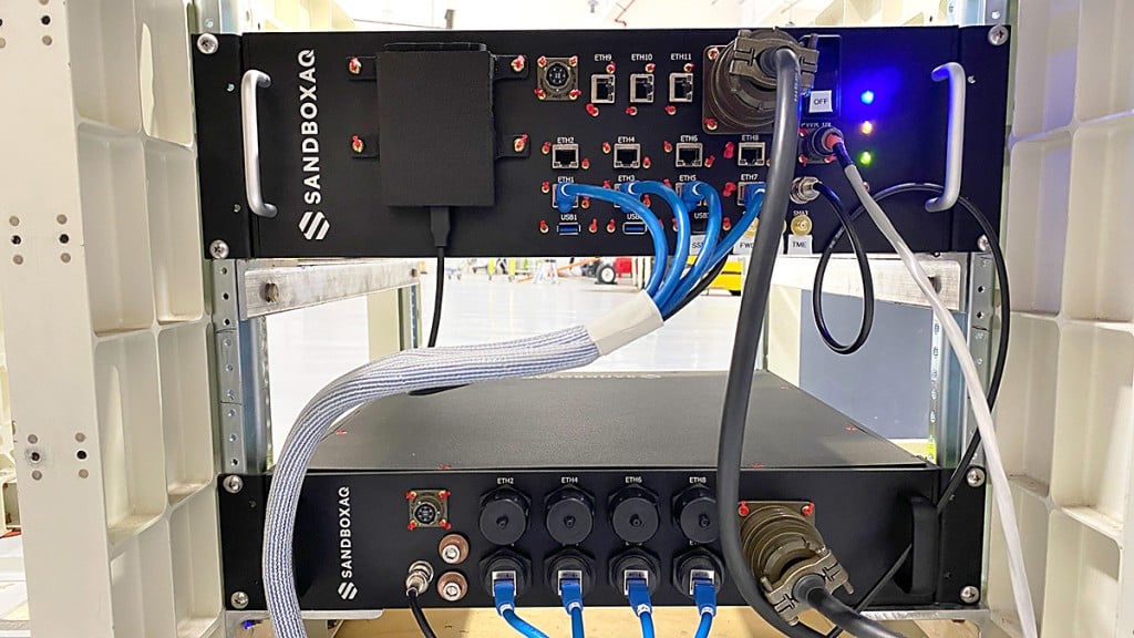
Corporate partners of the Chicago Quantum Exchange, including Boeing, Infleqtion and SandboxAQ, are among those developing applications. The CQE is a hub that connects leading universities, national labs, and industry partners to advance quantum technology.
“Governments and the commercial industry are in dire need of this technology,” said Ken Devine, senior product manager for quantum navigation at SandboxAQ. “The geopolitical issues happening across the world, and the ramp up in both jamming and spoofing — Russia, Ukraine, the Middle East, Israel, Iran — everyone’s getting super disruptive, and that’s not going to go away anytime soon. Everyone is saying, ‘We basically need this yesterday.’”
In May 2023, SandboxAQ completed the first of many flight tests for the United States Air Force and its commercial aviation partners, including two major Air Force exercises that year.
In 2024, Boeing completed the world’s first recorded flight using multiple quantum navigation systems, testing the ability of these sensors to navigate across the central U.S. for four hours without GPS.
The Boeing test incorporated two different technologies. The first is a magnetic field-based navigation system called AQNav from SandboxAQ, It uses map matching, though the map that they use is of the Earth’s crustal magnetic field rather than terrain. Infleqtion is investigating both techniques. The second is an inertial navigation system from quantum sensing technology company AOSense.
Jay Lowell, principal senior technical fellow at Boeing, said it was vital to consider “whether and how” the different technologies could be used together. “Maybe that means a tradeoff of performance between sensors in moments where one struggles and the other’s strong,” Lowell said. “Fundamentally, it means we just need to understand whether their combined data is better than either one alone.”
Detecting tiny changes
Inertial navigation depends on accelerometers and gyroscopes — which respectively measure acceleration and rotation — to measure movement. An inertial sensor tracks how an object moves from a known starting point by recording changes in its speed and direction.
While basic accelerometers are common in smartphones and fitness trackers, quantum inertial sensors can detect changes in motion down to the femtometer — less than the width of an atom — making them extraordinarily precise. Inertial sensors have applications in space-based technology, since they do not need maps or fixed points to navigate.
Infleqtion recently completed commercial flight trials of inertial-based quantum navigation in the United Kingdom and plans to conduct tests in the U.S. as well. Infleqtion’s Chicago office is also developing an AI-powered tool called SAPIENT that won first place in the U.S. Army’s xTechScalable competition.
“[SAPIENT] is focusing on the software side, taking the outputs of multiple kinds of sensors and stitching them all together with AI to provide a more robust navigation signal,” said Pranav Gokhale, general manager of computing at Infleqtion. “There is a big gap between an inertial measurement unit and a full inertial navigation system, so we’re using AI to fill that gap.”
Alternatively, magnetic navigation, or MagNav, works much like terrain-following radar, comparing real-time sensor data to a known map to pinpoint location.
But instead of elevation, the aircraft senses subtle magnetic fluctuations in the Earth’s crust — variations caused by geology, mineral deposits and even human infrastructure — and compares its measurements to a corresponding map of that field.
Scientists believe that birds can use their ability to sense the Earth’s magnetic field to navigate in a similar way. Magnetic field maps of the globe are frequently done for mineral, oil and gas surveys, as small anomalies in the field can indicate resources underground. But there are areas where high-resolution maps can be hard to come by.
“Map quality in the region you’re going to is definitely a factor that gets plugged into how well magnetic navigation can perform,” Devine said.
He identified a list of other key variables, such as the type of aircraft being used, plus its altitude and speed, as additional points of consideration for MagNav technology. At the same time, he said the importance of these tools is likely to grow as electronic warfare strategies become even more entrenched.
“We’ve validated that we can do real-time navigation with this technology,” Devine said. “And that’s huge, because the need for it is only going to increase.”
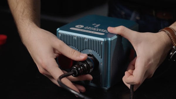
Advanced Navigation is moving forward with plans to establish international positioning, navigation and timing (PNT) Centers of Excellence, with the UK location selection process currently underway.
The company is evaluating potential sites based on access to technical talent, logistics capabilities and proximity to major international airports. The final UK center location will be announced in late 2025, with additional global centers confirmed in early 2026.
Over the past year, Advanced Navigation has doubled its workforce and significantly expanded manufacturing capacity to address surging defense sector demand. The international COE network represents the next phase of the company’s growth strategy, positioning it to double its team again within 12 months.
“In an era of increasing complexity and contested environments, the ability to navigate with absolute certainty is becoming the world’s most critical strategic asset,” the company stated.
Building Supply Chain Resilience
To complement its Australian operations and establish robust onshore supply chains meeting local standards and security requirements, Advanced Navigation plans to partner with regional specialists in critical PNT sensing technologies, including:
Inertial sensing (optical gyroscopes and MEMS)
Vision-based sensing
Lidar and radar sensing
Acoustic Doppler velocity log sensing
The company emphasizes that navigation’s future depends on integrating diverse, adaptable sensor suites rather than relying on single technologies. Through its multi-sensor approach centered on inertial systems, the company aims to deliver resilience even in severe GPS-contested environments.
The expansion will accelerate innovation cycles, strengthen quality assurance and create opportunities for partners and research institutions across America and Europe to collaborate on breakthrough technologies.
Strengthening NATO Capabilities
The strategic expansion directly addresses NATO forces’ evolving operational needs. By establishing presence within U.S. and European industrial landscapes, Advanced Navigation aims to bolster critical infrastructure resilience while creating collaboration opportunities and jobs.
Beyond scaling production, the centers will focus on enabling seamless interoperability across NATO’s land, sea and air platforms, reducing integration time and costs for member nations. The COE network positions the company to power the next generation of autonomous systems and alternative PNT solutions worldwide.
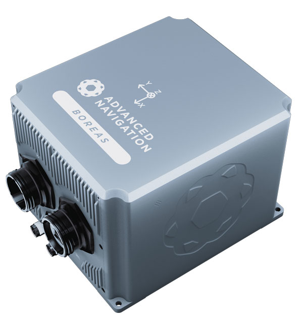
Advanced Navigation said the Boreas D90 FOG INS represents the type of technology that will be developed and manufactured at these new facilities.
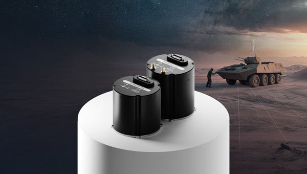
Advanced Navigation has released the Boreas 50 series, marking the company’s smallest fiber-optic gyroscope (FOG) inertial navigation system (INS).
The new product line consists of two devices, the A50 attitude and heading reference system and the D50 strategic-grade INS. Both units feature north-seeking gyrocompasses designed to determine true north without relying on GPS signals or magnetic references.
The 50 series weighs 910 g and incorporates Advanced Navigation’s sensor fusion technology, which processes data from multiple sensors to maintain accuracy during GPS outages or interference. The system can detect Earth’s rotation to establish directional orientation within minutes of activation.
An optional Electronic Counter-Countermeasure capability is available for the D50, designed to detect and counter GPS jamming and spoofing attempts. The feature targets operations in contested electromagnetic environments where adversaries may attempt to disrupt satellite-based navigation.
“The modern battlefield is no longer defined by only physical boundaries, but by electromagnetic dominance,” said Maximilian Doemling, head of product at Advanced Navigation. “Assuming navigation will ‘just work’ is a mission-critical oversight.”
Performance Specifications
The system achieves heading accuracy of 0.5° secant latitude through gyrocompassing, with roll and pitch accuracy of 0.03°. Positional accuracy reaches 0.01 m circular error probable at 50% confidence level when GPS is available.
The devices meet military standards for shock and vibration testing, addressing requirements for platforms operating in harsh environments. The compact form factor enables integration into space and weight-constrained systems.
Defense applications for the 50 series span multiple domains. Military pointing platforms, including radar systems, can use the technology for target tracking and identification while mobile or stationary. The system’s rapid stabilization capabilities support accurate targeting despite motion and environmental interference.
The Boreas 50 series is Advanced Navigation’s most compact FOG INS. (Credit: Advanced Navigation)
Counter-unmanned aircraft system platforms benefit from the precise heading and stabilization features when tracking aerial threats. The north-seeking gyrocompass enables rapid target acquisition and tracking in dynamic operational environments.
Maritime vessels operating under GPS-denied conditions can maintain navigation capabilities and threat identification through the system’s independent positioning features. The technology aims to preserve tactical advantages when satellite signals are unavailable.
Intelligence, surveillance and reconnaissance platforms, along with unmanned aircraft systems, can address navigation failures and targeting errors caused by electronic warfare and sensor drift. The compact design accommodates both new and legacy aircraft integration requirements.
Ground vehicles, whether autonomous or crewed, gain protection against electronic interference that could compromise navigation and situational awareness. The anti-jamming and anti-spoofing capabilities maintain consistent positioning data during operations.
Advanced Navigation‘s defense division consists of military veterans who collaborate with system integrators, program offices and end-users to develop tailored solutions. The company plans to double its defense team size within the year.
The firm’s vertically integrated manufacturing approach aims to reduce production lead times compared to industry standards. Products carry a three-year warranty, and the 50 series provides a direct upgrade path for users of the company’s existing Spatial FOG Dual system.
The technology represents ongoing development in assured positioning, navigation and timing systems as military operations increasingly face electronic warfare threats targeting GPS-dependent systems.
A roundup of recent products in the GNSS and inertial positioning industry from the June 2023 issue of GPS World magazine.
SURVEYING
Survey Software Georeference raw lidar data
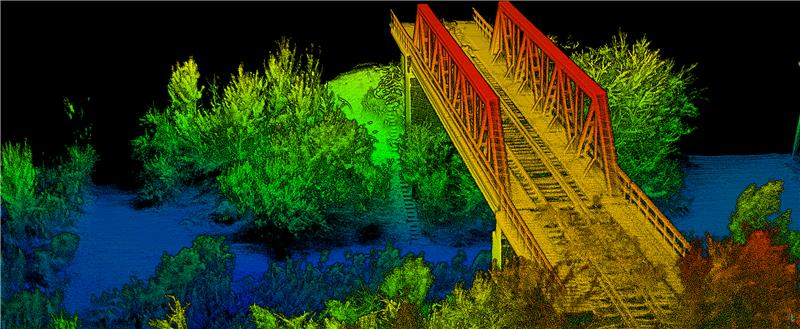
Georeferencer 2.5 featuring anyNAV software is suitable for survey applications. Users of Georeferencer 2.5 with the anyNAV feature enabled can boresight payloads and georeference lidar data using the user’s navigation data. The anyNAV software enables lidar surveyors to create accurate point clouds quickly. Georeferencer 2.5 now takes navigation data from third-party inertial navigation systems, which enables users to use that data to georeference raw lidar data from multiple sensor families. The resulting data can then be viewed in many point cloud viewer software packages. OxTS, oxts.com
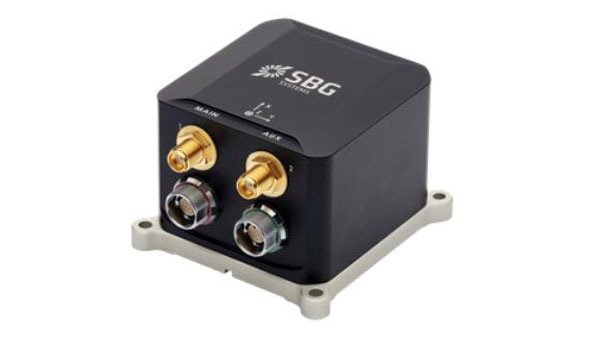
Inertial Navigation Solution Designed to deliver accuracy in challenging environments
Ekinox Micro combines a high-performance MEMS tactical inertial sensor with a quad-constellation, dual-antenna GNSS receiver, making it suitable for mission-critical applications. The device includes pre-configured motion profiles for land, air and marine applications, enabling the sensor and algorithms to be tuned for maximum performance in any condition. The device is designed for ease of use and integration, with simple connectors, a web configuration interface, datalogger, Ethernet connectivity, a PTP server, a REST API for configuration, and multiple input and output formats. Ekinox Micro is compatible with real-time kinematic (RTK) solutions and based on a tactical 0.8°/h class inertial measurement unit calibrated across the entire operating temperature range. It features accuracy roll/pitch of 0.015°, accuracy heading of 0.035°, and accuracy position of 1.2 m without any corrections or 1 cm in RTK. The device also meets the MIL-STD-461, MIL-STD-1275, and MIL-STD-810 standards. SBG Systems, sbg-systems.com
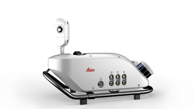
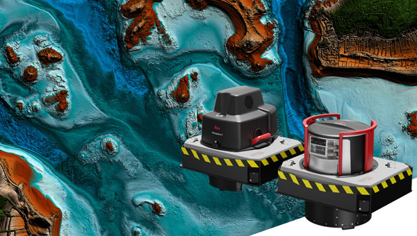
Lidar Sensor High-performance airborne bathymetric solution for deep water surveying
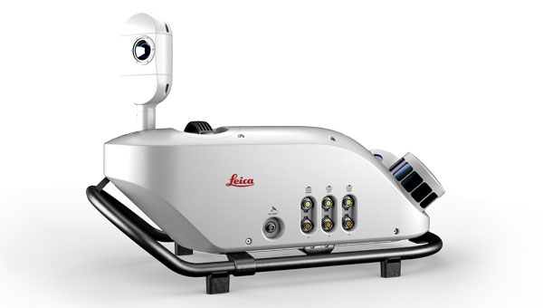
The HawkEye-5 increases survey efficiency by up to 25% compared to previous generations. The technology expands the capabilities of the Chiroptera-5 bathymetric lidar system, enhancing the productivity of applications such as nautical charting, environmental monitoring, and maritime surveillance in deep waters. The technology is designed to fit the Leica PAV100 gyro-stabilized mount, which isolates the sensor from unwanted aircraft movements — resulting in consistent data density and more efficient area coverage. The HawkEye-5 combined with the Chiroptera-5 features three lidar sensors, one four-band camera, and a QC camera to collect data from the seabed to land. Leica Geosystems, leica-geosystems.com
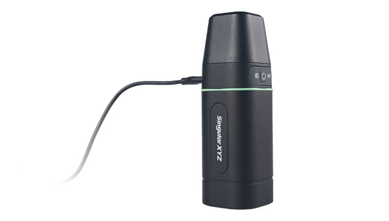
GNSS Receiver Complete with network RTK rover
The Sfaira One GNSS receiver is small and centimeter accurate. It provides users with an entry-level network real time kinematic (RTK) rover. Sfaira One is equipped with a GNSS module with 1,408 channels for GPS, BDS, GLONASS, Galileo and QZSS tracking — providing centimeter positioning in harsh environments. It also features advanced RTK and an anti-interference algorithm. The GNSS receiver connects via Bluetooth and can be configured to conduct surveying tasks on a smartphone. Additionally, Sfaira One supports SingularPad and SingularSurv software and is also compatible with mainstream field survey or GIS software. Sfaira One is IP65 dustproof and waterproof, which makes the receiver suitable for all weather conditions. It has a 4,800 mAh battery life with 16 hours working time and type-C interface that can be charged on-the-go with a power bank. SingularXYZ, singularxyz.com
MAPPING
Mobile Mapping Solution Built for large-scale infrastructure measurement and digital twin creation
The Pegasus TRK100 is small and light, making it easy to mount on any vehicle. The mobile mapping system features the same modular hardware approach that enables users to add more cameras to expand the range of use cases. With its advanced mapping capabilities, the Pegasus TRK100 enables GIS professionals to visualize and understand the location of assets to help make the right decisions, improve asset management, and support infrastructure building and maintenance. The Pegasus TRK100 combines artificial intelligence and a learning algorithm to enhance and optimize the clarity of points in post-processing for improved accuracy. The versatility of the Pegasus TRK100 suits a variety of applications in diverse industries, including telecommunications, utilities and road maintenance. Leica Geosystems, leica-geosystems.com
OEM
Photo:
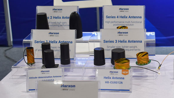
Helix Antenna Series Suitable for unmanned system applications
HX-CUX012A is designed with an extremely low profile, making it suitable for integration into UAVs, surveying and monitoring devices. It reduces the overall weight of applications, enables multipath mitigation and more. HX-CUX005A is a solution for integrated helix antenna applications. It is designed with the integration of a GNSS antenna and Bluetooth/Wi-Fi antenna, enabling communication and navigation without mutual interference. HX-CH7609A is a low profile and small size housed helix antenna. It has comprehensive GNSS support including GPS, GLONASS, Galileo, BeiDou, as well as L-band correction services. HX-CH7609A features centimeter phase center repeatability and high gain at a low elevation. With signal filtering and multipath rejection, it provides reliable and stable GNSS signals. HX-CHX600A is a high-performance helix antenna that receives GPS, Galileo, BeiDou, GLONASS, as well as L-band signals. With 4.2 dBi high gain, it provides suitable tracking performance at a low elevation angle. Its low noise figure design reduces transmission interference and improves signal quality. Harxon, en.harxon.com
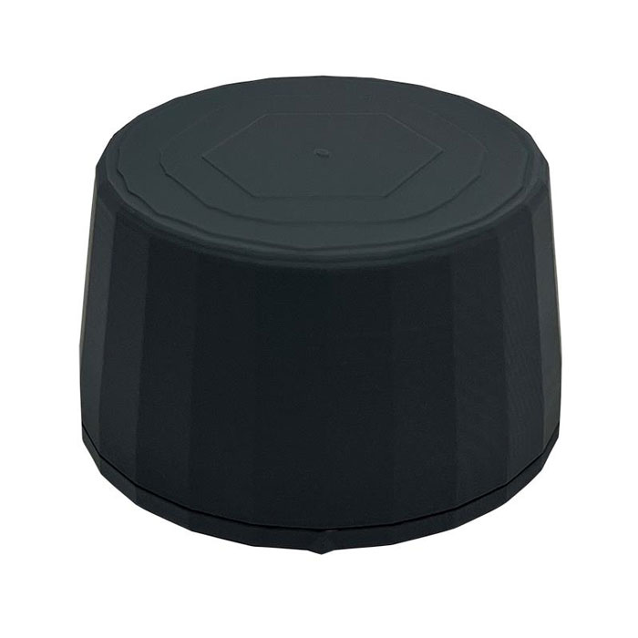
Helical Antenna Suitable for UAV applications
The HC990XF helical antenna is designed for precise positioning, covering the GPS/QZSS L1/L2/L5, QZSS L6, GLONASS G1/G2/G3, Galileo E1/E5a/E5b/E6, BeiDou B1/B2a/B2b/B3, and NavIC L5 frequency bands. This includes the satellite-based augmentation system (SBAS) available in the region of operation as well as L-band correction services. The HC990XF has a base diameter of 64 mm, is 37 mm tall and weighs 45 g. Its precision-tuned helical element provides full GNSS band coverage, suitable gain and axial ratio, and a tight phase center. The antenna base has an SMA (male) connector, three screw holes for secure attachment and an O-ring to waterproof the antenna connector. The HC990XF helical design does not require a ground plane, making it a suitable antenna for UAV applications. Tallysman Wireless, tallysman.com
Inertial Module For automotive uses
The ASM330LHB automotive-qualified MEMS inertial-sensing module provides accurate measurements for a wide variety of vehicle functions. With the dedicated software provided, ASM330LHB also addresses functional-safety applications up to ASIL B1. ASM330LHB contains a 3-axis digital accelerometer and 3-axis digital gyroscope that provides a six-channel synchronized output. The module’s high-accuracy inertial measurements are used to improve the precise positioning of a vehicle. The accelerometer and gyroscope maintain high stability over time and temperature, and have very low noise for an overall bias instability of 3°/hour. Specified over the extended temperature range, -40°C to 105°C, the ASM330LHB has multiple operating modes that let designers optimize the data-update rate and power consumption.
ASM330LHB can support advanced driver assistance systems or vehicle-to-everything communication, as well as help stabilize sensing systems such as radar, lidar and visual cameras, and assist semi-automated driving applications up to L2+. Additionally, ASM330LHB can be used to enable a variety of functionalities in the body of a vehicle. ASM330LHB was developed with the automotive functional-safety standard ISO 26262 — the ASIL B compatible software library has been certified independently by TÜV SÜD. By implementing dedicated safety mechanisms, including data integrity and accuracy, the library ensures compliance with ASIL B automotive systems.
With the companion software engine, the ASM330LHB supports the growing adoption of automotive systems that require safety integrity up to level B. The combination of two ASM330LHB sensor modules for fail-safe redundancy delivers resilient contextual data for driver-assistance applications such as lane centering, emergency braking, cruise assistance and semi-automated driving. ASM330LHB is AEC-Q100 qualified and in production now in a 2.5 mm x 3.0 mm 14-lead VFLGA package. STMicroelectronics, st.com
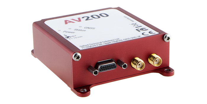
INS Built for automation applications
The AV200 is designed to give precise location data. It includes quad-constellation, dual-antenna, real-time kinematic (RTK) GNSS to provide users with position data as well as its temperature-calibrated, multi-core inertial measurement unit. These technologies give the AV200 position accuracy within 0.05 m, heading accuracy of 0.2°, and velocity accuracy of 0.2 km/h. The AV200 is built using the same technology that is commonly used for NCAP test validation, which has become the preferred technology for OEMs globally to test vehicles in both test-track and real-world scenarios. OxTS, oxts.com
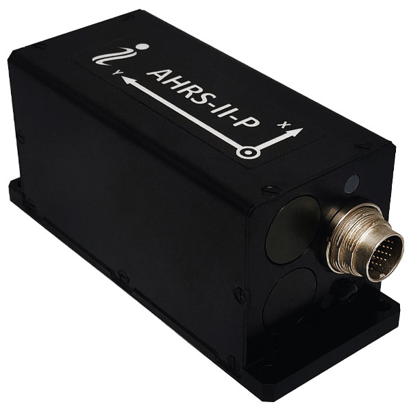
Reference System For attitude and heading
AHRS-II-P is an enhanced, high-performance strapdown system that determines absolute orientation (heading, pitch and roll) for any mounted device. The AHRS-II-P can determine orientation for both motionless and dynamic applications. The AHRS-II-P contains a tactical-grade inertial measurement unit (IMU) consisting of three high-precision MEMS accelerometers, three advanced MEMS gyroscopes and a high-precision, gyro-compensated, embedded fluxgate compass. It also uses 8 mm fluxgate magnetometers. This device is suitable for a variety of devices such as UAVs, antennas, ships and robotic devices.
Inertial Labs, inertiallabs.com
GNSS Receiver For accurate positioning and heading
As a high-precision integrated GNSS positioning and heading receiver, the A200 can track all existing and planned constellations — including GPS, BSD, GLONASS, Galileo, QZSS and SBAS — providing high-precision positioning and heading data for users. A200 is designed specifically for precision agriculture, machine control, fleet management, robot and other industries. The A200 is equipped with a K823 GNSS module. It also features 1,226 channels. The A200’s third generation IMU delivers fast initialization and ensures the output of heading during temporary GNSS signal loss. The built-in data link has low power consumption and a long working range. It also can be upgraded to a super-long-range data link module. ComNav Technology, comnavtech.com
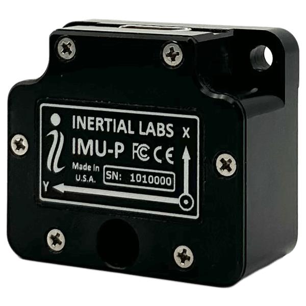
Inertial Labs has launched its inertial measurement unit-P (IMU-P). It is an advanced MEMS sensors-based, compact, self-contained strapdown, industrial- and tactical-grade inertial measurement system and digital tilt sensor that measures linear accelerations, angular rates and pitch-and-roll with three-axis, high-grade MEMS accelerometers and three-axis, tactical-grade MEMS gyroscopes.
Angular rates and accelerations are determined with high accuracy for both motionless and dynamic applications.
Like Inertial Labs IMU-FI-200C, the IMU-P is fully calibrated, temperature compensated, and mathematically aligned to an orthogonal coordinate system. IMU-P demonstrates less than 1 deg/hr gyroscopes and 0.005 mg accelerometers bias inrun stability with low noise and high reliability.
The IMU-P models collect data from an external source of GNSS to output full spectrum inertial navigation system data consisting of positions, attitude, velocity and time.
The IMU-P is suitable for applications such as antenna and line of sight stabilization systems, GPS-aided INS, UAV & AUV/ROV navigation and control and more.
A roundup of recent products in the GNSS and inertial positioning industry from the February 2023 issue of GPS World magazine.
SURVEYING & MAPPING
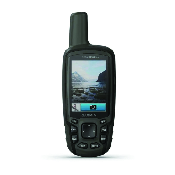
GPSMAP 64csx handheld GPS receiver (Image: Gamin)
Handheld GPS With navigation sensors and camera
The GPSMAP 64csx handheld GPS receiver comes with multi-GNSS support, TopoActive mapping, barometric altimeter, three-axis compass, and wireless connectivity via Bluetooth and ANT+ technology. It also has an 8 MP autofocus camera. The GPSMAP 64csx is built to withstand rugged terrain and is water-resistant. The highly sensitive receiver and quad helix antenna provide support from GPS, GLONASS and Galileo. Preloaded TopoActive maps include waterways, natural features, buildings and international boundaries. It is compatible with smartphones so users can receive email and text messages and share location data with others. Garmin, garmin.com
The Venus Laser RTK receiver comes with an inertial measurement unit. It can be used in its traditional mode with a range pole, or in laser mode without a pole, enabling GNSS surveying beyond typical limitations. In traditional mode, it has tilt compensation of up to 60° with an accuracy of 2.5 cm; in laser mode, it has the same tilt compensation but an accuracy of 5.5 cm. The receiver is powered by a SinoGNSS K8 high-precision module capable of up to 1,590 channels. It can survey using GPS, BDS-2, BDS-3, GLONASS, Galileo, QZSS and SBAS constellations. Other features include Bluetooth connectivity, more than 20 hours of battery life, and ruggedness (it is dust and waterproof and is designed to survive a two-meter drop). ComNav Technology Ltd., comnavtech.com
Leica iCON gps 160 (Image: Leica Geosystems)
Smart Antenna With features to increase productivity on the construction site
The Leica iCON gps 160 is a next-generation construction smart antenna designed to increase productivity in stakeout and measurement applications on the jobsite. It features a large color display with clear navigation for quick and easy setup without additional hardware. It is optionally available with an inertial measurement unit (IMU) for tilt-compensation functionality up to 20°. It seamlessly integrates with all Leica iCON construction instruments and controllers as well as the iCON field software for precise, real-time verification. Leica Geosystems, leica-geosystems.com
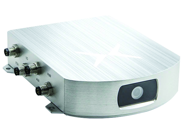
The Xsens Vision Navigator (Image: Movella)
GNSS inertial navigation Integrates position inputs from three high-accuracy sources
The Xsens Vision Navigator integrates position inputs from three high-accuracy sources including dual-antenna real-time kinematic (RTK) GNSS receivers; an inertial measurement unit (IMU) incorporating a three-axis accelerometer, a gyroscope and magnetometer; and a visual inertial odometry system. It can optionally accept input from an external wheel-speed sensor. The positioning sensor achieves centimeter-level accuracy when operating in GNSS mode with an RTK fix. When GNSS signals are not available, the product alone achieves accuracy of 2% of travel distance, or 0.75% when supplemented by wheel speed. Xsens Vision Navigator is suitable for outdoor positioning applications such as material handling equipment, commercial and specialist vehicles, last-mile delivery, inspection equipment and UAVs, agricultural equipment, mining equipment and utility robots. Movella, movella.com
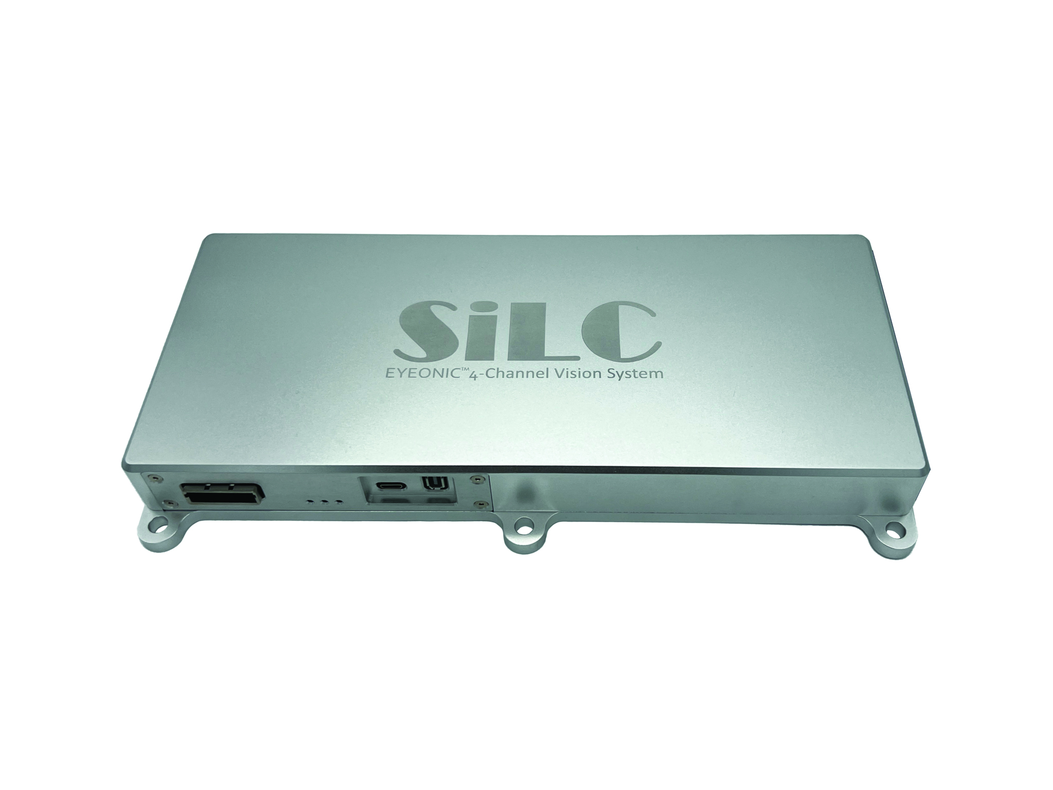
SILC Eyeonic Vision System (Image: SiLC)
Coherent Vision Solution Delivers high levels of vision perception
The Eyeonic Vision System is a frequency-modulated continuous wave lidar solution, which delivers high levels of vision perception to identify and avoid objects with low latency. At the core of the Eyeonic Vision System is a fully integrated silicon photonics chip. It provides more definition and precision than legacy lidar solutions, with roughly 10 milli-degree of angular resolution coupled with millimeter-level precision. These features enable this solution to measure the shape and distance of objects with high-precision and at a large distance. The system combines the Eyeonic Vision Sensor and a digital processing solution based on a powerful field-programmable gate array. The flexible architecture enables synchronization of multiple vision sensors for unlimited points per second.
SiLC, silc.com
OEM
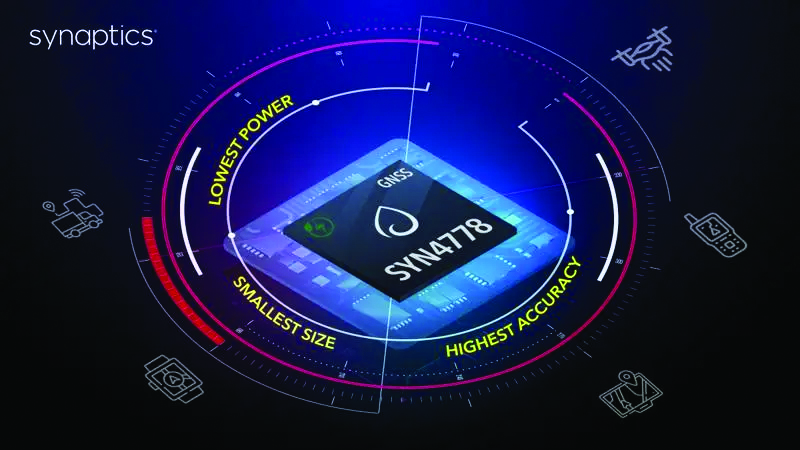
The SYN4778 (Image: Synaptics)
Integrated Circuit Designed for the internet of things
The SYN4778 is a small, low-power GNSS integrated circuit designed to extend battery life, reduce product size, and enhance performance of advanced location-based services for internet of things (IoT) devices — wearables, mobile accessories, asset trackers, UAVS and transportation devices. It includes advanced multipath interference mitigation using L5-band signals from GPS, Galileo, BeiDou, NAVIC, SBAS and QZSS. The chip also uses the L1 satellite band to reduce both the time to first fix, and the power consumed, improving the end-user experience and enabling product developers to add additional functionality and features to their IoT devices. Synaptics, synpatics.com
The Boreas D70 is a fiber-optic gyroscope (FOG) inertial navigation system (INS), part of the Boreas digital FOG series. The technology is suited to surveying, mapping and navigation across subsea, marine, land and air applications. It also could be adopted for vehicular applications, including autonomous vehicles and aircraft where weight and size are at a premium. The Boreas D70 combines closed-loop DFOG and accelerometer technologies with a dual-antenna real-time kinematic (RTK) GNSS receiver. These are coupled with an artificial-intelligence-based fusion algorithm to deliver accurate and precise navigation. Advanced Navigation, advancednavigation.com
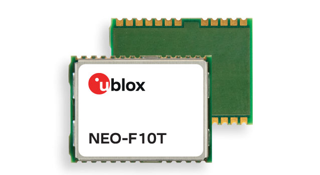
The u-blox NEO-F10T (Image: u-blox)
Timing Module Dual-band and secure for 5G communications
The u-blox NEO-F10T offers nanosecond-level timing accuracy, meeting the stringent timing requirements for 5G communications. It is compliant with the u-blox NEO form factor (12.2 mm x 16 mm), allowing space-constrained designs to be realized without the need to compromise on size. The NEO-F10T is the successor to the NEO-M8T module, providing an easy upgrade path to dual-band timing technology. This allows NEO-M8T users to access nanosecond-level timing accuracy and enhanced security. u-blox’s dual-band technology mitigates ionospheric errors and greatly reduces timing error, without the need for an external GNSS correction service. u-blox, u-blox.com
TRANSPORTATION
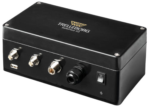
SafePilot P3 (Image: Trelleborg)
Maritime Systems Provides data on vessel positioning
The SafePilot P3 navigation system provides real-time data on vessel positioning and movement in tight waterways. It uses motion sensors and two GNSS antennas to measure the position and heading of vessels in three dimensions, minimizing time and difficulty associated with piloting procedures. SafePilot P3 has a backup battery to maintain functionality in the event of a power outage. This navigation system improves situational awareness while navigating waterways and ports globally, and also enhances communication between the captain, pilot, tug operators and canal personnel while vessels are transiting a canal and approaching a port.
Trelleborg, trelleborg.com
FusionEngine software (Image: Point One Navigation)
Positioning Engine Assures functional safety of ASIL-B
FusionEngine software, which is rated for automotive safety integrity level (ASIL), is now compatible with STMicroelectronics’ Teseo ASIL Precise Positioning GNSS chipset TeseoAPP. This assures functional safety of ASIL-B, a requirement for Level 3+ advanced driver assistance systems (ADAS). It can be integrated into several different host processors to enable high-level ADAS and autonomous driving systems. The combination of TeseoAPP’s receiver and the STA5365S external RF front-end provides dual-band measurement data for all visible GNSS satellites to the main host processor into which
FusionEngine is integrated. Point One Navigation, pointonenav.com
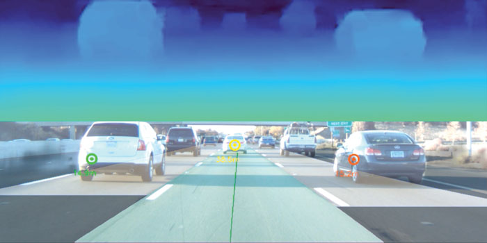
Ghost Autonomy Engine (Image: Ghost)
Autonomous driving software for level 4 driver assistance
The Ghost Autonomy Engine achieves the reliability required to bridge the gap between driver assistance capabilities L2 or L2+, and self-driving that does not rely on a human backup (L4). The software provides a stereo-vision neural network that delivers per-pixel depth in real time. It is capable of detecting and segmenting key features in a scene without needing to classify or recognize them. The physics-based perception system can handle the long tail of obstacles on the road, even those never seen before. Ghost, ghostautonomy.com
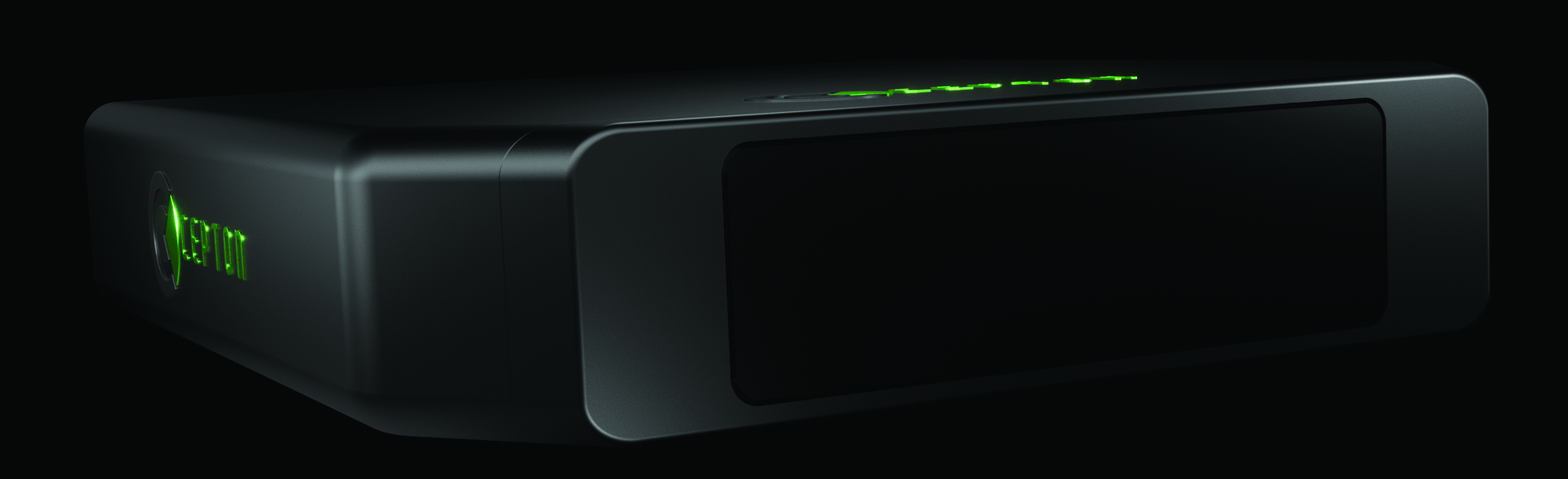
Vista-X120 Plus (Image: Cepton)
Lidar Provides 3D perception
The Vista-X120 Plus is a slim automotive lidar device for real-time adaptive 3D perception for advanced driver assistance. Its software-definable region of interest enables higher dynamic perception capabilities, while an adjustable central field of view with increased angular resolution improves accuracy in detection and classification of objects when driving. The region of interest is also configurable in real time in both horizontal and vertical directions. The Vista-X120 Plus is compact at 140 mm x 30 mm, improving OEM integration and placement options without disrupting vehicle appearance. Cepton, cepton.com
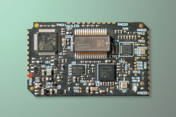
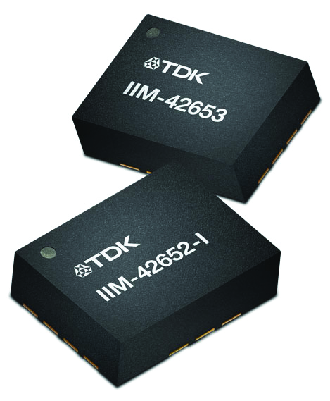
IIM-42653 and IIM-42652-I sensor platforms (Image: TDK Corporation)
Sensor Platforms Targets industrial and navigation applications
The IIM-42653 and IIM-42652-I sensor platforms consist of 6-axis IMUs, which target industrial and navigation applications requiring high force sensitive resistor (FSR) performance or inertial navigation software. The IIM-42653 platform — a robust, low-noise, low-power, 6-axis IMU — is capable of a gyro-programmable output of 4,000 dps and an accelerometer-programmable output of 32 g. These features make the IIM-42653 suitable for industrial-grade or high-end automated guided vehicles, automated mobile robots and unmanned aerial vehicles. The IIM-42652-I platform offers hardware authentication and can be integrated with TRACK dead-reckoning software from Trusted Positioning. TRACK filters GNSS multipath errors and provides a continuous navigation solution when GNSS signals are unavailable. TDK Corporation, invensense.tdk.com
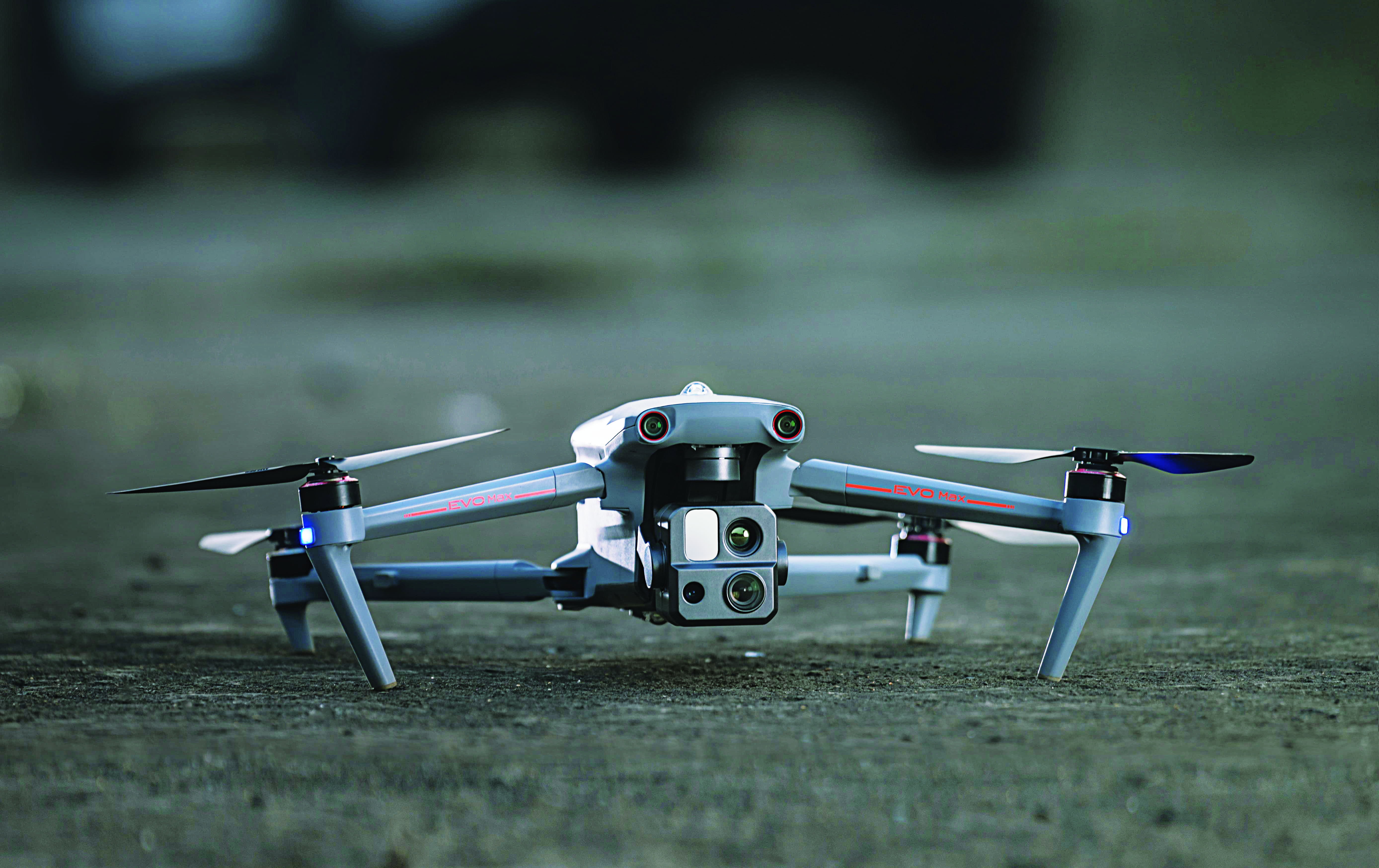
VO Max 4T (Image: Autel Robotics)
Flight Platform
For enterprise and professional applications
The EVO Max 4T autonomous flight platform provides omnidirectional obstacle avoidance and tri-anti-interference capability to ensure flight safety and stability in high-interference environments. It is equipped with three high-quality cameras including a 48 MP telephoto camera, a 50 MP wide-angle camera and an infrared camera. The platform has a range of navigation and data-acquisition functions, including 3D flight routes, PinPoint Mode, Team Work, Polygon Mission, Waypoint Mission and Oblique Photography. EVO NEST is a base for automatic take-off, landing, charging and mission planning for EVO series UAVs. It is designed for all-weather operation and can be easily transported. Autel Robotics, autelrobotics.com
Initial value of the contracts is expected to be more than $12 million
Emcore Corporation has been awarded new contracts for the Booster Rate Gyro (BoRG) and Tri-Axial Inertial Measurement Unit (TAIMU) programs for space launch vehicles resulting from its acquisition of the L3Harris Space and Navigation business.
The BoRG program award is a contract valued at more than $12 million for the production of IMUs used for flight stabilization of the booster stage of a multistage launch system. The TAIMU program award is a development contract for the design and qualification of IMUs deployed for navigation and flight control of the upper stage of a multistage launch system.
Pending successful demonstration of required capability and quality, Emcore expects to be awarded follow-on production contracts for TAIMU within the next 12 months.
“We are honored to supply our highest grade inertial navigation equipment for these critical space launch vehicle programs,” said Albert Lu, senior vice president and general manager, Aerospace and Defense for Emcore. ”We look to further our close partnership with L3Harris through successful on-time deliveries for both the BoRG and TAIMU programs,” Lu added.
The acquisition expands Emcore’s inertial navigation product portfolio with the addition of navigation-and strategic-grade gyro and inertial measurement unit products.
Emcore acquired all outstanding assets and liabilities of the L3Harris Space and Navigation business, including all L3Harris intellectual property rights primarily used in the Space and Navigation business, a 110,000-square-foot leased production facility in Budd Lake, New Jersey, and associated production equipment.
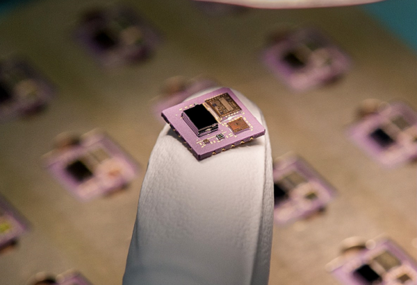
Safran Electronics & Defense is taking a major step forward in its inertial navigation strategy by grouping two subsidiaries, Safran Colibrys (Switzerland) and the recently acquired Sensonor (Norway,) under a single banner, Safran Sensing Technologies.
The similarities in expertise, market position, customers and technologies result in clear synergy between these two companies, which produce accelerometers, gyrometers and inertial measurement units (IMUs). The creation of Safran Sensing Technologies shows Safran’s commitment to developing its micro-sensor business through these two companies.
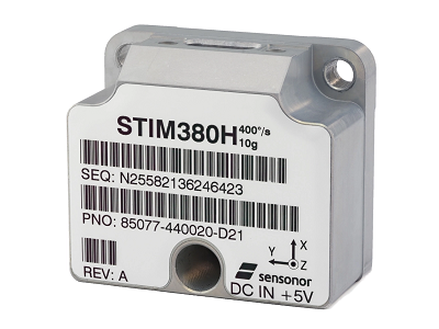
The STIM380H inertial measurement unit. (Photo: Sensonor)
The goal is to jointly offer a wider and comprehensive range of inertial technologies including vibrating sensors, optics and micro-electromechanical system (MEMS) for applications in aeronautics, defense, space and other industries.
The two subsidiaries have already delivered more than 20 million MEMS sensors to the aeronautics, defense, space, transport, mobility and industry sectors. For example, MEMS are used in the control accelerometers of automobile airbags, in high temperature accelerometers for guiding drill heads, and in seismic sensors measuring the structural health of buildings or civil engineering works. They are also used in IMUs for civil, military and space vehicles.
This change is part of a broader Safran Electronics & Defense strategy designed to strengthen the company’s position in the positioning, navigation and timing (PNT) market.
The two entities have been renamed Safran Sensing Technologies Norway AS and Safran Sensing Technologies Switzerland SA, respectively.
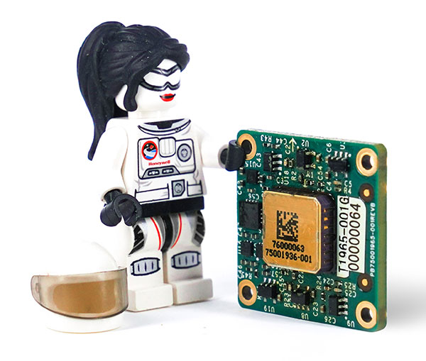
A LEGO Minifigure beside the MV60 shows its small size. (Photo: Honeywell)
Honeywell has unveiled a new accelerometer that delivers high performance and reliability in a small, rugged and low-cost package. The MV60 micro-electromechanical system (MEMS) accelerometer is designed for aerospace and defense, but also has potential uses in industrial and marine applications that require high-precision, navigation-grade accelerometers that are small, lightweight and require little power to operate.
The MV60 measures the acceleration experienced by an object during movement. These types of high-accuracy sensors are mainly used in inertial measurement units and navigation systems deployed on land, air and sea vehicles to measure velocity.
Additionally, inertial systems provide:
key orientation information for drilling operations
precision pointing and altitude determination for vehicles
platform stabilization
target location and surveying.
“The MV60 accelerometer is a technological breakthrough that leverages 50 years of Honeywell inertial sensor and MEMS experience to offer excellent reliability, ruggedness and performance,” said Matt Picchetti, vice president, Navigation and Sensors, Honeywell Aerospace. “Our customers in a wide range of markets will benefit from an accelerometer that is smaller, lighter and requires less power over similar offerings, and they won’t have to sacrifice performance.”
The highly reliable Honeywell MV60 accelerometer features a compact footprint of 1.2 square inches and has shock survivability of up to 5,000 g (g-force). It also offers bandwidth of greater than 300 Hz (hertz) — important for environmentally demanding missions.
The MV60 delivers accuracy and performance that previously had only been available in more expensive solutions. Now, customers have a more affordable, rugged, and small-scale offering suitable for the most demanding navigation applications.
Accelerometers are critical elements of navigation systems, and Honeywell provides a portfolio of precision accelerometers that deliver reliable performance at affordable prices to meet customer needs.
A U.S. Secretary of Defense once predicted that navigation would eventually be based on inertial devices that were set at the factory, and then always knew where they were forever after. Recently published research has reported on steps in that direction. However, according to navigation expert Brad Parkinson, the outlook is not as bright as some might think.
RNT Foundation President Dana A. Goward recently discussed the issue with him.
Goward: Dr. Parkinson, you are well known for your contributions as the chief architect of the Global Positioning System. But you have more than a passing familiarity with inertial systems also, is that right?
Parkinson: I do. Long before I was involved in radio navigation, I was the chief analyst for all the U.S. Air Force testing of inertial navigation systems. I earned my masters degree in Doc Draper’s Inertial Lab at MIT in 1961. I am a major advocate and defender of inertial systems. I also have in-depth understanding of their limitations.
Goward: Have you been following the recent media coverage about advances with inertial systems?
Parkinson: I enjoy reading about these advances in physics devices. At the same time, I am a little impatient with media articles that do not appreciate the differences between building a device that measures specific force (or senses rotation) and a working inertial navigation system.
Goward: What are some of the inherent limitations of these systems?
Parkinson: I find it interesting that some of the articles speculate they may be able to supplant GPS and other GNSS. There is no way an inertial navigation system, even with perfect gyros and force sensors, can provide its accurate position (say, better than 10 meters) after extended periods (hours to days). In fact, attaining better than 200 meters accuracy after a few hours will be very difficult in a moving vehicle.
Today, farmers require even greater accuracy from GPS. They routinely use GPS for row operations, with accuracies of a few centimeters. The economic value is indirectly measured by the farmer’s purchase of such equipment — the agriculture market for GPS equipment is well over a billion dollars a year. Thus, a general replacement for GPS must provide centimeter accuracies.
Goward: So, what is it about inertial systems that stands in the way of them becoming autonomous substitutes for GPS?
Parkinson: There are some very simple and fundamental reasons that inertial positioning systems cannot hope to deliver such capability.
First, force sensors are not accelerometers, because they cannot sense gravity. To find acceleration, one needs to add vector gravity to their outputs. But gravity, or g force, varies a lot at the micro-g levels, and the inaccuracies are fed to the double integration that produces position. Errors grow as time or time squared and, without outside reset, are essentially unbounded. The physics devices described in some of these articles are definitely instruments that Doc Draper described as “specific force sensors.”
What we loosely call g force, or just g, is actually the inverse of the reaction to maintain stationarity on Earth. G is defined to include the centrifugal force due to Earth’s rotation, which varies greatly as a function of latitude — the radius of the merry-go-round called Earth. Mountains and chasms affect the local g. Further, it is a vector quantity: its direction can change locally by many arc seconds. In other words, down does not generally point to Earth’s center. Gravity gradiometers might be of limited help, but they are very large and not made for dynamic environments.
In a nutshell, estimating acceleration requires calculating and adding gravity to the three-dimensional specific force sensor.
Second, to use these devices for extended navigation, coordinate frames would have to be defined and stable to milli-arc seconds. All instruments would have to have input axes and cross-axis sensitivity calibrated to corresponding levels. Generally, this problem is ignored in many lab projects.
Third, for inertial navigation sensors to work, they need to accurately know their initial position. Any initial velocity or position errors will grow as a function of time.
Fourth, the vertical position axis is inherently unstable and diverges exponentially.
Physicists have been enamored with instruments that can use atoms to sense specific force and rotation. While scientifically interesting, even if perfect they cannot overcome these challenges.
Goward: But there is still a role for inertial systems in navigation, isn’t there? How good are they, and what are some of the applications?
Parkinson: I suspect the best inertial systems of today (which are in nuclear submarines) can maintain an accuracy of about 0.1 nautical miles or about 200 meters for a few days. I am sure the real number is classified. These systems are very large, expensive and complicated. They rely on a very low acceleration environment and are periodically reset with GPS. Furthermore, they probably use gravity gradiometry to calculate the local variations in gravity to the first order. They do not calculate the vertical position, and use water density and knowledge of the local geoid to keep the vertical axis stable.
An aircraft with inertial can, to some extent, keep the vertical dimension errors bounded, provided it has knowledge from elsewhere of local sea-level barometer settings and by assuming adiabatic pressure variations.
I strongly support the inertial/GPS/directional antenna marriage for users who want assured PNT. Aviation is a good use case for this. Inexpensive inertial components (called micro-electromechanical systems, or MEMS) can improve the jamming resistance of the GPS receiver by 15 dB or more. This step alone can reduce the effective line-of-sight jammer denial area by more than 95%.
Goward: So, inertials can be a good part of the solution but are not necessarily the whole solution themselves.
Parkinson: Exactly. Despite what some media outlets might publish to lure in readers.
At the ION GNSS+ 2021 conference in St. Louis, Missouri, the annual meeting of the Satellite Division of the Institute of Navigation, Brad Parkinson bestowed Lakshay Narula with the division’s Bradford W. Parkinson Award for his Ph.D. thesis “Towards Secure & Robust PNT for Automated Systems” at the University of Texas at Austin. The award honors Parkinson, known as the “father of GPS,” for his leadership in establishing both GPS and the Satellite Division of the ION. Narula is now an applied scientist at Amazon Lab126 in Sunnyvale, California, where he researches robust navigation and state estimation methods for robots, from self-driving cars to aerospace applications. (Photo: ION)
How inertial systems and GNSS availability will help
By Kana Nagai, Matthew Spenko, Ron Henderson and Boris Pervan
Self-driving cars in urban environments can be problematic. The required multi-sensor automated systems will include GNSS, but buildings block and reflect GNSS signals, reducing system availability and accuracy. Researchers from the Illinois Institute of Technology report on how inertial navigation systems coupled with wheel-speed sensors and vehicle dynamic constraints can help.
Innovation Insights with Richard Langley
ARE WE THERE YET? This was a familiar refrain from the backseats of parents’ cars when traveling to a holiday destination or to grandparents when I was growing up. We didn’t have videos on a display attached to the seats in front of us or (who could imagine?) our own personal communication device on which we could call up games, movies or social media channels.
But I’m not talking about that complaint from our childhoods. I’m asking if we have arrived at the era of the self-driving car. The answer is yes and no. It all depends on what you mean by “self-driving.” We reviewed some of the technologies needed for self-driving or autonomous vehicles in this column in June 2019. And we indicated in the introduction to that column that vehicle autonomy has several levels. SAE International, formerly known as the Society of Automotive Engineers, has defined six levels of autonomy that can be briefly described as Level 0 – no automation; Level 1 – hands on/shared control; Level 2 – hands off; Level 3 – eyes off; Level 4 – mind off; and Level 5 – steering wheel optional.
Already, Level 1 automation is widely available in modern cars with adaptive cruise control, parking assistance, lane-keeping assistance and automatic emergency braking among the features being offered.
Level 2 automation, where the automated system takes full control of the vehicle’s acceleration, braking and steering, is available in some production models, although the “hands-off” designation is not to be taken literally — most motor vehicle laws require drivers to keep their hands on the steering wheel.
Between Level 2 and Level 3, we have conditional automation — the car can drive itself, but the driver must stay alert and be prepared to take over immediately.
Level 3 is high automation, where a computer fully drives the car at certain times on certain routes such as a highway; while the driver can perform other tasks such as reading a book, they must be prepared to take over operation of the vehicle within a few seconds if alerted by the automated system. While test campaigns are still ongoing, some jurisdictions permit Level 3 operation by ordinary drivers on some roads, and customers will soon be able to buy vehicles with this level of automation. Widespread use of
Level 4 and Level 5 automation is further off (some would say quite a way off) and remains in development. But famously, last year, Toyota operated Level 4 self-driving shuttle vehicles around the Tokyo 2020 Olympic Village.
A lot more work needs to be done before we will have arrived at the era of the fully self-driving car that will be able to travel on any road, anywhere in the world, all year around, in all weather conditions. In particular, self-driving cars in urban environments (as opposed to highway driving) can be problematic.
The required multi-sensor automated systems will include GNSS, but buildings block and reflect GNSS signals, reducing system availability and accuracy. In “Innovation” this month, researchers from the Illinois Institute of Technology report on how inertial navigation systems coupled with wheel-speed sensors and vehicle dynamic constraints can help.
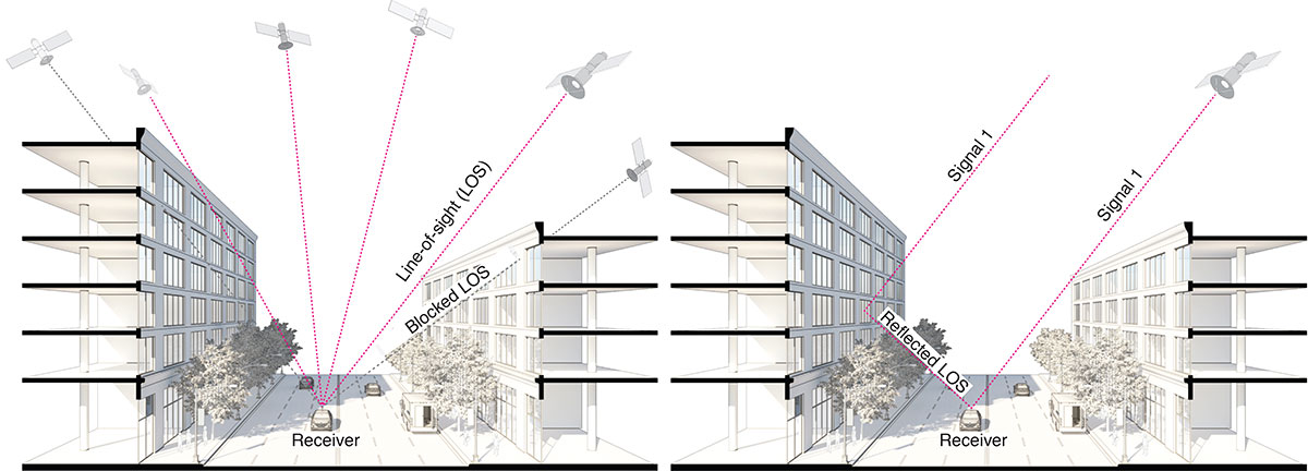
GNSS provides navigation services globally, but satellite visibility in urban areas is limited by high-rise buildings. This creates a mixture of GNSS available and denied environments (see FIGURE 1) — users do not generally know where the system can maintain sufficient levels of accuracy and integrity for a particular application. To begin to address the issue for self-driving cars, we evaluated GNSS-only availability in downtown Chicago.
FIGURE 1. The figure depicts three types of potential GNSS signal reception: direct LOS signals and blocked LOS signals (left) and reflected LOS signals (right). (Image: Authors)
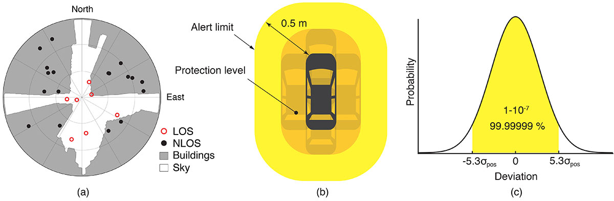
GNSS signal prediction in urban environments has been conducted in previous work. For example, the concept of “shadow matching” was developed to identify GNSS signal blockages in urban canyons. Overlaying sky plots on a hemispherical sky view can be used to distinguish between line-of-sight (LOS) and non-line-of-sight (NLOS) signals (see FIGURE 2a). Reflected rays can be predicted using Householder transformations to reveal potential multipath conditions. Satellites producing blocked or reflected (NLOS) signals should be excluded to maintain integrity.
FIGURE 2. (a) A hemispherical sky view in an urban environment. (b) Illustration of a protection level and an alert limit. To ensure integrity, the protection level must not exceed an alert limit. (c) The allowable probability of exceedance is assumed to be 10−7 in this work. (Image: Authors)
When the number of visible satellites is greater than three, GNSS can resolve vehicle position. However, even in cases where enough satellites are visible, the satellite geometries are generally weak because the dilution of precision (DOP) is adversely affected by the buildings partially blocking the sky. Horizontal positioning error must be bounded by a protection level computed by the vehicle. Then, for navigation to be deemed available, the protection level must not exceed a required alert limit (see FIGURE 2b). The maximum allowed probability of exceedance (see FIGURE 2c) and the alert limit can together be used to determine the maximum allowable position error standard deviation.
Even if the protection level is far below the alert limit in an open-sky environment, it will frequently exceed the alert limit once the vehicle enters a city. GNSS alone is generally not able to maintain availability, so integration with other sensors is needed. Tightly coupling inertial navigation systems (INS) with GNSS using the extended Kalman filter (EKF) provides better estimation in urban environments. The EKF algorithm also enables integration of wheel-speed sensors and vehicle dynamic constraints. These integrated navigation systems will improve availability, but it is still unclear how long such a system can be expected to maintain fault-free integrity in a congested city.
Focusing on the problem of self-driving cars in urban environments, we evaluate protection levels of navigation with practical integrated sensors: GNSS, INS, a wheel-speed sensor (WSS) and vehicle dynamic constraints (VDC). The goal is to develop the means by which we can determine locations where external ranging sources (such as lidar) are needed to maintain continuous navigation with fault-free integrity.
GNSS-ONLY AVAILABILITY
For GNSS availability evaluation, we assume an integrity requirement that the probability of exceeding a 0.5-meter alert limit must be lower than 10−7. The 0.5-meter alert limit therefore corresponds to approximately five times the position standard deviation, so the maximum allowable position error standard deviation is then approximately 0.1 meters. Accuracy at this level clearly requires differential GNSS carrier-phase measurements. We assume a nominal GNSS double difference (DD) carrier ranging error standard deviation of approximately 0.02 meters, and that carrier cycle ambiguities can be readily resolved in an open-sky environment prior to initiation of vehicle motion.
Given the assumptions made of the maximum allowable position error standard deviation and the GNSS ranging error standard deviation, the maximum allowable horizontal dilution of precision (HDOP) is about 5.
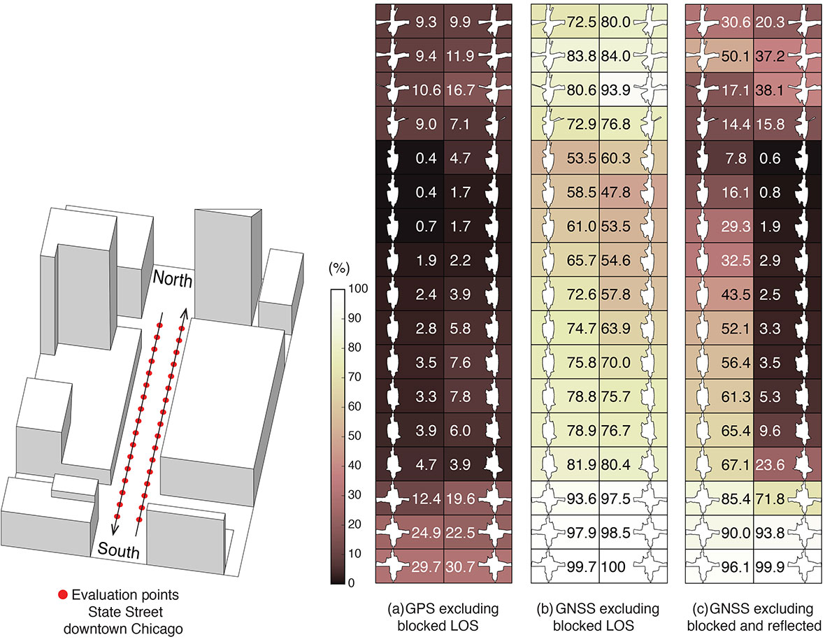
FIGURE 3 shows GPS and GNSS availability — the fraction of time the HDOP requirement is met over 24 hours — along a section of State Street in downtown Chicago. The availability results using GPS only and excluding only blocked LOS signals ranged from 0% to 9% along the block and 9% to 30% at the intersections (see FIGURE 3a). Using four full GNSS constellations (GPS, Galileo, GLONASS and BeiDou), availability ranged from 48% to 82% along the block and 72% to 100% at the intersections (see FIGURE 3b).
FIGURE 3. The percentage of GPS or GNSS availability in 3D-mapped downtown Chicago. We exclude satellites producing blocked LOS signals or both blocked and reflected LOS (NLOS) signals from the measurements. Each column expresses a lane of southbound or northbound travel. The availability is the percentage of total time when HDOP meets the self-driving car integrity requirements in 24 hours. (Image: Authors)
When we also excluded satellites producing reflected LOS signals that reach the vehicle, the availability dropped significantly at every point (see FIGURE 3c). We assert that FIGURE 3c expresses the reality of GNSS availability because building-reflected multipath signals degrade positioning accuracy and would affect integrity negatively. It’s obvious from these results that GNSS alone is insufficient to meet the autonomous driving requirements in an urban environment, and multi-sensor integrated navigation systems are needed to augment poor GNSS signal availability.
MULTI-SENSOR INTEGRATION
We begin by considering tightly coupled INS/GNSS integration using an EKF, and then integrate a realistic sensor suite including WSS and vehicle dynamic constraints that enforce resistance to lateral sliding and vertical movement. If it is known from another source that the vehicle is not moving (for example, it is in the parking gear), a static mode constraint (SMC) can also be applied.
INS/GNSS Integration. Tightly coupled INS/GNSS integration with an EKF uses the INS measurement to predict vehicle motion. The continuous process model uses a state vector having the position in the navigation frame, the velocity, the attitude, bias errors and cycle ambiguities, with the input vector having accelerometer-specific force measurement in the body frame and gyro-rotation-rate measurements. A white-noise vector drives the inertial measurement unit (IMU) states.
The GPS/GNSS measurement model includes the measurement vector having carrier and code phases, and the observation matrix containing LOS vectors and the vector of white receiver thermal noise.
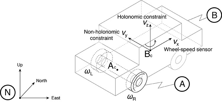
INS/GNSS/WSS/VDC Integration. For the vehicle in motion, we developed a model consisting of a WSS measurement in the along-track direction, a non-holonomic constraint resisting lateral sliding, and a holonomic constraint on vertical movement (see FIGURE 4).
The INS/GNSS/WSS/VDC integration using the EKF consists of the process model and the measurement models.
FIGURE 4. The measurement model consisting of the WSS measurement in the along-track direction (vx), non-holonomic constraint resisting lateral sliding (vy), and holonomic constraint on vertical movement (vz). N is the navigation frame, Ac is the rear-axle center point and Bc is the center point of the body-fixed frame. (Image: Authors)
INS/GNSS/SMC Integration. The static mode constraint provides zero-velocity measurements to the EKF measurement update to mitigate position error propagation. We use SMC only when it is known that the vehicle is not moving; for example, when the vehicle is in the parking gear.
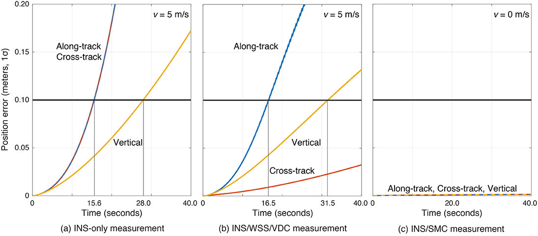
Error Propagation Analysis. We tested the time from perfect initialization to when position error exceeds 0.1 meters in GNSS-denied environments. FIGURE 5 shows the error growth in the along-track (x), the cross-track (y) and the vertical (z). The error specifications for a STIM300 tactical-grade IMU are used in this analysis. The standard deviation of the WSS measurement noise is assumed to be 0.05 meters per second, and the standard deviation of the movement constraint violations is 0.001 meters per second. The vehicle is moving at 5 meters per second except when we test the SMC.
The INS can coast 15.6 seconds before the position error standard deviation exceeds 0.1 meters in both the along-track and the cross-track directions (see FIGURE 5a). The INS/WSS/VDC can coast 16.5 seconds in the along-track direction, and significantly more than 40 seconds (the simulation duration) in the cross-track direction (see FIGURE 5b). In static mode, INS/SMC estimate errors do not grow with time in any direction, as expected (see FIGURE 5c). In GNSS-denied environments, the non-holonomic constraint suppresses the cross-track position error, but the WSS measurement hardly affects the along-track position error. The SMC works perfectly, but the usage is limited to when the vehicle is known to be stationary.
FIGURE 5. The vehicle position error growth vs. time in the along-track (x), cross-track (y) and vertical (z) directions. Each graph represents the navigation system introduced in the multi-sensor integration section. The vehicle is moving at 5 meters per second (a and b) or 0 meters per second (c). (Image: Authors)
SIMULATION SCENARIO
We imagine a future driverless-car mission scenario in which multi-sensor navigation systems are practicable. To minimize congestion in a city, autonomous vehicles will be held outside the urban core when not in use. In the clear open-sky environment, a vehicle in a parking lot completes GNSS initialization using the INS/GNSS/SMC system. Once requested for action, the vehicle departs for the city from the parking lot, and the motion of the vehicle improves alignment by the INS/GNSS system. Safe navigation can be ensured using the system to provide continuity under overpasses and bridges in the open-sky environment. Upon entering the urban core, navigation becomes more dependent on the INS/WSS/VDC system.
A reasonable numerical target for differential GNSS initialized position error is 0.02 meters, and for the INS alignment yaw angle error 0.1 degrees.
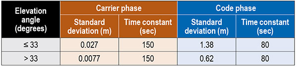
Local GNSS multipath errors from nearby vehicles will vary with the satellite elevation angle. Prior experimental results show that lower elevation-angle satellite signals (below 33 degrees) are much more likely to be impacted by multipath than higher ones (see TABLE 1).
Table 1. The nominal GNSS multipath error values in the simulation.
INITIALIZATION AND ALIGNMENT
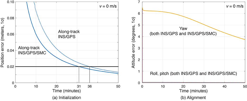
Initialization takes place in a parking lot with a clear sky view. A vehicle is in the parking gear, enabling SMC to be applied. FIGURE 6a shows a typical example: with INS/GPS/SMC, system initialization takes about 31 minutes, and with INS/GPS, about 36 minutes. Therefore, SMC does speed up GPS initialization, although the improvement is modest.
The yaw angle is not aligned during the initialization, but roll and pitch are immediately aligned (see FIGURE 6b). Earth’s gravity affects roll and pitch angle alignment but not yaw angle.
Yaw angle alignment cannot be performed when the vehicle is stationary or moving with constant velocity. Accelerated motion, either straight or turning, is required.
FIGURE 6. (a) Comparisons of initialization time between INS/GPS and INS/GPS/SMC in an open-sky environment. The INS/GPS/SMC system initializes rapidly. (b) Transitions of roll, pitch, yaw alignment during the initialization. Yaw angle alignment cannot be performed when the vehicle is stationary. (Image: Authors)
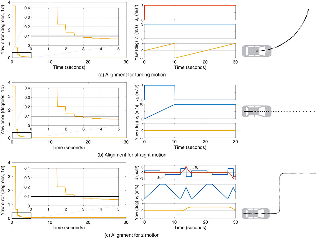
FIGURE 7 shows the behavior of the yaw angle error standard deviation using the INS/GPS system when centripetal (see FIGURE 7a) or tangential (see FIGURE 7b) acceleration is applied. The yaw angle can be aligned in a couple of seconds for either type of acceleration. To represent typical initial motions of self-driving cars, we model a parking-lot departure via a “Z”-shaped path. In this scenario, the yaw alignment error reaches 0.1 degrees within a couple of seconds (see FIGURE 7c).
FIGURE 7. The behavior of yaw angle error when centripetal (a) or tangential (b) acceleration is applied; (c) shows the behavior while following a z-shaped path. The yaw angle can be aligned in a couple of seconds in each case. (Image: Authors)
EVALUATION IN URBAN ENVIRONMENTS
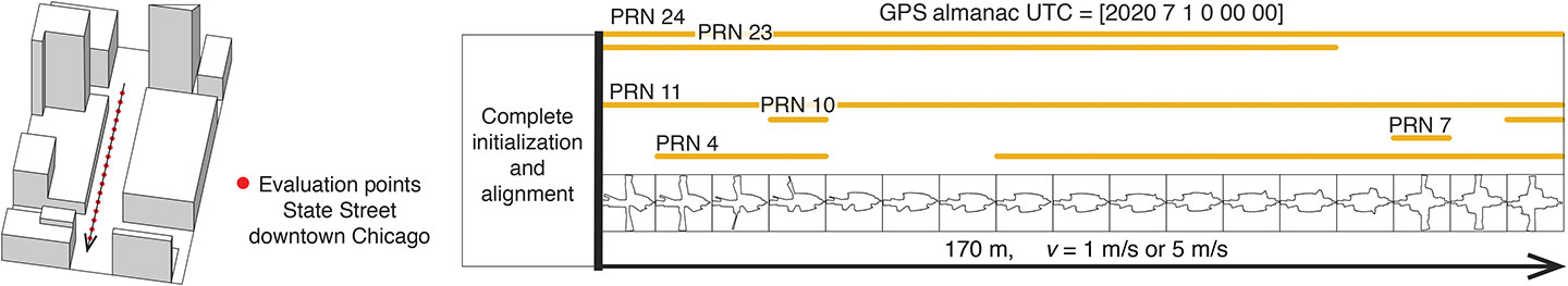
After initialization and alignment in the open-sky environment, we simulated the vehicle traveling into the urban core. The urban environment in our study is 3D-mapped State Street in Chicago, which runs north-south and transits from low-rise neighborhoods to central downtown. We selected one congested section surrounded by tall buildings and computed the position error standard deviation along the path. The evaluation points are at 10-meter intervals over a total distance of 170 meters. The yellow lines in FIGURE 8 denote the visible satellites, identified by their pseudorandom noise (PRN) code numbers, at each point. We assume for convenience that the INS/GPS system is initialized and aligned at the first evaluation point. In reality, we would expect a degraded initial condition because we are starting the simulation in an urban canyon.
FIGURE 8. Evaluation points and PRN numbers of visible satellites at each point. (Image: Authors)
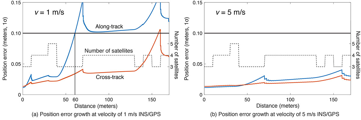
In the first simulation, the car equipped with the INS/GPS system moved either 1 or 5 meters per second. The y-axis in FIGURE 9 represents the position error standard deviation, and the x-axis represents the distance in meters. The dotted line expresses the number of visible satellites. The error when the vehicle velocity is 1 meter per second exceeded the maximum allowable position error standard deviation of 0.1 meter, at the distance of 60 meters. However, when the velocity was 5 meters per second, the maximum allowable position error standard deviation was never reached. It is also clear from the figures that error propagation is significantly affected by the number of visible satellites.
FIGURE 9. A comparison of position error growth between velocities of 1 meter per second and 5 meters per second. (Image: Authors)
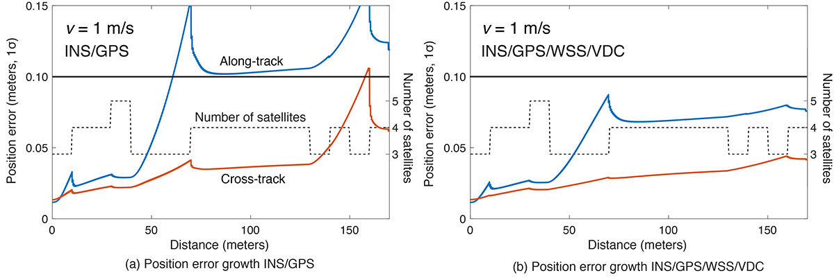
In the second simulation, we compared two different navigation systems, INS/GPS and INS/GPS/WSS/VDC. The vehicle moved at 1 meter per second in the same urban environment. The INS/GPS/WSS/VDC system does provide relief, but the error propagation is still clearly affected by the number of visible satellites (see FIGURE 10).
FIGURE 10. A comparison of position error growth between the INS/GPS and INS/GPS/WSS/VDC systems for a velocity of 1 meter per second. (Image: Authors)
In GNSS-challenged environments, INS error propagation is a function of time. When a vehicle moves faster, it clears the blockage area more quickly, reducing the impact of INS drift — a function of time, not distance. In contrast, GNSS error is completely determined by location. Because INS error propagation depends on how long the vehicle stays in an area of GNSS outage, protection levels for trips through the same area will be different if the vehicle is smoothly cruising or gets stuck in a traffic jam.
CONCLUSION
To gain a better understanding of how long and under what local conditions multi-sensor integrated navigation systems can maintain fault-free integrity, we evaluated navigation positioning errors in 3D-mapped downtown Chicago. The system we developed consists of sensors with which self-driving cars would reasonably be equipped: GNSS, INS, WSS and dynamic constraints. We showed that INS/GPS position errors along the path depend very strongly on the vehicle’s speed. When the system is augmented with WSS/VDC, position errors are suppressed, but the error propagation is still strongly influenced by the number of visible satellites.
ACKNOWLEDGMENTS
The research described in this article is supported by the National Science Foundation. Figure 1 was created by Alexis Arias of the Landscape Architecture + Urbanism Program at the Illinois Institute of Technology (IIT). The authors greatly appreciate the advice and help of Nilay Mistry from that program.
This article is based on the paper “Evaluating INS/GNSS Availability for Self-Driving Cars in Urban Environments” presented at ION ITM 2021, the virtual 2021 International Technical Meeting of The Institute of Navigation, Jan. 25–28, 2021.
KANA NAGAI is a Ph.D. candidate and research assistant in mechanical and aerospace engineering at IIT.
MATTHEW SPENKO is a professor of mechanical and aerospace engineering at IIT. He earned his M.S. and Ph.D. degrees in mechanical engineering from the Massachusetts Institute of Technology.
RON HENDERSON is a professor and director of the Landscape Architecture + Urbanism Program at IIT. He earned his Master of Landscape Architecture and Master of Architecture from the University of Pennsylvania.
BORIS PERVAN is a professor of mechanical and aerospace engineering at IIT. He earned his M.S. from the California Institute of Technology and Ph.D. from Stanford University.