Another GLONASS-M satellite was launched on June 17 from Plesetsk Cosmodrome.
A Fregat booster carried satellite GLONASS-M 59 to its designated orbit, the Russian Defense Ministry said in a statement on Sunday, as reported by Russian News Agency TASS.
“The Soyuz 2.1-b carrier rocket, launched at 00:46 Moscow time from the Plesetsk space center (Arkhangelsk Region), put the Russian GLONASS-M navigational satellite into the designated orbit at the scheduled time,” the statement read.
Ground-based facilities of the Titov Main Test and Space Systems Control Centre of the Russian Space Forces have assumed control of the satellite.
Telemetry communication with the spacecraft is stable and the onboard systems function normally.
By Sergey Karutin, GLONASS designer general; Nicolay Testoedov, Director General, SC Information Satellite Systems; and Andrey Tulin, Director General, SC Russian Space Systems
This year has marked the 35th anniversary of the first GLONASS launch. During these years, the world has made great strides through high tech, and now no modern society can progress without satellite-based navigation.
Today’s urban resident can hardly do without a smartphone planning his route through traffic, determining the paid parking site location or getting a reminder of parking session completion once he has left the parking lot.
The search for the nearest pharmacy, gas station, restaurant or any other point of interest is of vital necessity today. The growing dependence of modern society on navigation signals-in-space increases the responsibilities of GNSS providers. At the same time, users long for simplicity in getting quality services. That is why this year the GLONASS team is going to set up its most ambitious program: improving the quality of the GLONASS services at a user level.
The traditional GLONASS conception of signal-in-space accuracy is now being augmented by the user level performance estimation. Due to the fact that the signal propagation environment contributes a lot to the positioning error budget, it is obvious that users need information that would reduce the influence of signal propagation path on the positioning accuracy.
Glonass-M satellites currently form the core of the GLONASS constellation, and with six ground spares now in stock, they will continue to do so for at least the next eight years. Therefore, in 2018 the new edition of L1 and L2 FDMA Interface Control Documents are to be published which will include the ionospheric and tropospheric models recommended in the recently released GLONASS CDMA Signals ICDs.
Glonass-K2 satellite (artist’s rendering).
We plan to use the spare bits within the navigation superframe of FDMA signals to transmit ionospheric parameters described in the General Description of the GLObal NAvigation Satellite System with the Code Division Multiple Access Signals ICD.
Studies being performed demonstrate up to 70 percent reduction in impact of ionospheric refraction when using the adaptive model transmitted by the three parameters: the numerical factor for the peak TEC (Total Electron Content) of F2 ionosphere layer, the solar activity index and the daily geomagnetic activity index. In the new CDMA signal message, these parameters are initially provided.
To enable the unanimity of technologies for reducing the hydrostatic component of the tropospheric delay, which accounts for 80 percent of its value, the both FDMA and CDMA Signals ICDs will include the latitudinal tropospheric model based on the preliminary set tabular values.
The preliminary design review for the technical baseline of the fourth-generation Glonass-K2 satellite has been passed this year. The new cubic arrangement of the platform enables mitigation of unmodeled forces and transition of propellant tank to the satellite’s center of mass.
This provides for the relative position constancy for the satellite’s center of mass and the satellite’s antenna phase center during the satellite’s lifetime. This platform arrangement also accommodates the whole ensemble of navigation signals (both CDMA and FDMA) on the single phased-array antenna system.
Glonass-K2 is equipped with the new atomic frequency standard composed of the legacy quantum frequency standard based on the cesium beam tube and the passive hydrogen maser. The miniature PHM with the relative daily stability of 5×10-15 will be installed onboard the satellite to be launched in 2020.
Introduction of the new satellite will enable a new constellation sustainment strategy — through the both dual launches by Angara-A5 launcher from Vostochny and single launches by Soyuz from Plesetsk — to provide on-demand replenishment of the constellation.
By 2020, when we celebrate the 25th anniversary of GLONASS full operational capability, all the efforts mentioned above will offer new quality of services to GLONASS users prioritized as per their needs.
A review of the history of the GLONASS program, its current status and an overview of the plans for the immediate future of the satellite constellation, its navigation signals and the ground support network.
English versions of the GLONASS CDMA interface control documents are now available. See Further Reading.
Richard Langley
On Oct. 12, 1982, the Soviet Union launched the first GLONASS satellite. Whether in reaction to the development of GPS or simply to fulfill the requirement for a system with similar capabilities for its armed forces, the Soviet Union began the development of the Global’naya Navigatsionnaya Sputnikovaya Sistema or Global Navigation Satellite System in 1976 just three years after the start of the GPS program. The first test satellite, code-named Kosmos 1413, was accompanied by two dummy or ballast satellites with the same approximate mass since the Soviet Union was already planning to launch three GLONASS satellites at a time with its powerful rockets to save on launch costs.
But because of launch failures and the characteristically brief lives of the satellites, a further 70 satellites were launched before a fully populated constellation of 24 functioning satellites (providing full operational capability or FOC) was achieved in early 1996. Unfortunately, the full constellation was short-lived. Russia’s economic difficulties following the dismantling of the Soviet Union hurt GLONASS. Funds were not available, and by 2002 the constellation had dropped to as few as seven satellites, with only six available during maintenance operations! But Russia’s fortunes turned around, and with support from the Russian hierarchy, GLONASS was reborn. Longer-lived satellites were launched, as many as six per year, and slowly but surely a full constellation of 24 satellites returned. And on Dec. 8, 2011, FOC was again achieved and has been subsequently more or less maintained — the system has even operated sometimes with in-orbit spares.
While GLONASS-only and survey-grade dual-system GPS/GLONASS receivers have been around for more than a decade, manufacturers took notice of GLONASS’s rebirth and began producing chips and receivers with GLONASS capability for the consumer market. In 2011, Garmin released handheld receivers supporting both GPS and GLONASS. In the same year, various cell-phone manufacturers started offering GLONASS capability with their embedded positioning modules. The early GPS/GLONASS receivers paved the way for the multi-GNSS receivers we have today, with their capability to track not just GPS and GLONASS satellites but those of the European Galileo and Chinese BeiDou systems, as well as those of the Japanese Quasi-Zenith Satellite System (not to mention the satellites of the satellite-based augmentation systems).
I documented the development of GLONASS in this column back in July 1997, and a team of authors from the Joint Stock Company Russian Space Systems discussed the plans for modernizing GLONASS in an April 2011 article. An update is overdue. So, in this article, I will briefly review the history of the GLONASS program, discuss its current status, and overview the plans for the immediate future of the satellite constellation, its navigation signals and the ground support network.
EARLY YEARS, PRESENT DAY
During the Cold War, information about GLONASS was scarce. Apart from the general characteristics of the satellite orbits and the frequencies used for transmitting the navigation signals, the Ministry of Defence of the Soviet Union revealed little else. However, sleuthing by Professor Peter Daly and his students at the University of Leeds provided some details about the signals’ structure. With the advent of glasnost and perestroika, and the eventual demise of the Soviet Union, information about GLONASS became more readily available. Eventually, the Russians released the Interface Control Document (ICD). This document, similar in structure to the Navstar GPS Space Segment/Navigation User Interfaces ICD-GPS-200, describes the system, its components, and the structure of the signal and the navigation message intended for civil use. Its latest version was published in 2016, but so far this version is only publicly available in Russian.
Satellites and Signals. Six models of GLONASS satellites (also known as Uragan, Russian for Hurricane) have been launched so far. Russia (actually the former Soviet Union) launched the first 10 satellites, called Block I, between October 1982 and May 1985. It sent up six Block IIa satellites between May 1985 and September 1986 and 12 Block IIb satellites between Apri1 1987 and May 1988, of which six were lost because of launch-vehicle-related failures. The fourth model was the Block IIv (v is the English transliteration of the Russian alphabet’s third letter). By the end of 2005, the Russians had deployed 60 Block IIvs. Each subsequent satellite generation contained equipment enhancements and also achieved longer lifetimes.
A prototype GLONASS-M (for Modernized) satellite was launched on Dec. 1, 2001, along with two Block IIvs with the first two production GLONASS-M satellites included in the triplet launches of Dec. 10, 2003, and Dec. 26, 2004. Two GLONASS-M satellites were included in the triplet launch of Dec. 25, 2005. The new design offered many improvements, including better onboard electronics, a longer lifetime, an L2 civil signal, and an improved navigation message. Like earlier versions, the GLONASS-M spacecraft still used a pressurized, hermetically sealed cylinder for the electronics.
FIGURE 1. Image from Reshetnev Information Satellite Systems, manufacturer of the GLONASS satellites, celebrating the 35th anniversary of the launch of the first GLONASS satellite in 1982 (“35 years of service to the world”).
All GLONASS satellites launched since December 2005 have been GLONASS-M satellites with the exception of two GLONASS-K1 (sometimes referred to as just GLONASS-K) satellites, launched on Feb. 26, 2011, and Nov. 30, 2014. GLONASS-K1 satellites are markedly different from their predecessors. They are lighter, use an unpressurized housing (similar to that of GPS satellites), have improved clock stability and a longer, 10-year design life. They also include, for the first time, code-division-multiple-access (CDMA) signals on a third frequency accompanying the legacy frequency-division-multiple-access signals (I’ll discuss these shortly). All of the GLONASS satellites have been manufactured by the Joint Stock Company Reshetnev Information Satellite Systems, located in Zheleznogorsk near Krasnoyarsk in central Siberia, and named after Mikhail Fyodorovich Reshetnev, the founding general director and chief designer. The Reshetnev company was formerly known as the Scientific Production Association of Applied Mechanics (Nauchno Proizvodstvennoe Ob”edinenie Prikladnoi Mekaniki or NPO PM). The Roscosmos State Corporation for Space Activities (formerly the Federal Space Agency), commonly known as Roscosmos, is the governmental body responsible for GLONASS.
FIGURE 1 includes artist’s images of the initial GLONASS, GLONASS-M and GLONASS-K1 satellites.
GLONASS satellite orbits are arrayed in three planes, separated from one another in right ascension of ascending node by 120 degrees, with eight satellites in each plane. The satellites within a plane are equally spaced, separated in argument of latitude by 45 degrees. Satellites in adjoining planes are shifted in argument of latitude by 15 degrees. The satellites are placed into nominally circular orbits with a target inclination of 64.8 degrees and semimajor axis of approximately 25,510 kilometers, giving them an orbital period of about 675.8 minutes. These satellites have ground tracks that repeat every 17 orbits or eight sidereal days. The GLONASS orbit planes are numbered 1–3 and contain orbital slots 1–8, 9–16 and 17–24, respectively.
FIGURE 2 shows the status of the constellation on Oct. 17, 2017. The orbital slot number (also called almanac slot) and frequency channel (discussed below) are given in parentheses. The recently launched GLONASS 752 was set healthy on Oct. 16, 2017, resulting in a fully operational 24-satellite constellation. All of the satellites are standard GLONASS-M satellites except for GLONASS 755, which includes a transmitter for the new third frequency, and GLONASS 701K and 702K. These last two are GLONASS-K1 satellites, with 702K operational while 701K is undergoing flight tests. The “K” isn’t part of the official GLONASS number but has been added to avoid ambiguity. A GLONASS-M satellite launched on Dec. 10, 2003, was also called GLONASS 701. Similarly, the International GNSS Service (IGS) refers to GLONASS 701K and 702K as 801 and 802, respectively. IGS also designates GLONASS 751 as GLONASS 851 to prevent confusion with Kosmos 2080, a GLONASS-IIv satellite launched on May 19, 1990, and also called GLONASS 751. And it designates GLONASS 753 as GLONASS 853 to prevent confusion with Kosmos 2140, a GLONASS-IIv satellite launched on April 14, 1991, and also called GLONASS 751.
FIGURE 2. Status of GLONASS constellation on Oct. 17, 2017. A green square identifies the location of a healthy satellite and orange, a test satellite. Orbital slot numbers and frequency channels are given in parentheses.
The satellites have been traditionally launched three at a time by Proton boosters from the Baikonur Cosmodrome near Leninsk in Kazakhstan. However, starting with the launch of the first GLONASS-K1 satellite, several GLONASS satellites have been launched singly on Soyuz rockets from the Plesetsk Cosmodrome north of Moscow.
Unlike GPS and the other GNSSs, GLONASS uses FDMA rather than CDMA for its legacy signals. Originally, the system transmitted the signals within two bands: Ll, 1602.0–1615.5 MHz, and L2, 1246.0–1256.5 MHz, at frequencies spaced by 0.5625 MHz at L1 and by 0.4375 MHz at L2:
L1k = 1602. + 0.5625k (MHz)
L2k = 1246. + 0.4375k (MHz)
This arrangement provided 25 channels, so that each satellite in the full 24-satellite constellation could be assigned a unique frequency (with the remaining channel reserved for testing). Some of the GLONASS transmissions initially caused interference to radio astronomers, who study very weak natural radio emissions in the vicinity of the GLONASS frequencies. Radio astronomers use the frequency bands of 1610.6–1613.8 and 1660–1670 MHz to observe the spectral emissions from hydroxyl radical clouds in interstellar space, and the International Telecommunication Union (ITU) has afforded them primary user status for this spectrum space. Also, ITU has allocated the 1610–1626.5-MHz band to operators of low-Earth-orbiting mobile communications satellites. As a result, the GLONASS authorities decided to reduce the number of frequencies used by the satellites and shift the bands to slightly lower frequencies.
The system now uses only 14 primary frequency channels with k values ranging from –7 to +6, including two channels for testing purposes (currently –5 and –6). (The +7 channel has also been used in the past for testing purposes.) How can 24 satellites get by with only 14 channels? The solution is for antipodal satellites — satellites in the same orbit plane separated by 180 degrees in argument of latitude — to share the same channel. This approach is quite feasible because a user at any location on Earth will never simultaneously receive the signals from such a pair of satellites. The move to the new frequency assignments started in September 1993.
Like the legacy GPS signals, the GLONASS signals include two pseudorandom noise (PRN) ranging codes: ST (for Standartnaya Tochnost or Standard Precision) and VT (for Visokaya Tochnost or High Precision) similar to the GPS C/A- and P-codes, respectively (but at half the chipping rates), modulated onto the L1 and L2 carriers.
As with GPS, GLONASS transmits the high-precision code on both L1 and L2. But, unlike the GPS satellites, the GLONASS standard-precision code has also been transmitted on the L2 frequencies beginning with the GLONASS-M satellites. (A separate civil code, L2C, has been added to the GPS L2 signal transmitted by Block IIR-M and subsequent satellites.) The GLONASS ST code is 511 chips long with a rate of 511 kilochips per second, giving a repetition interval of 1 millisecond. The VT-code is 33,554,432 chips long with a rate of 5.11 megachips per second. The code sequence is truncated to give a repetition interval of 1 second. Unlike GPS satellites, all GLONASS satellites transmit the same codes. They derive signal timing and frequencies from one of the onboard atomic frequency standards (AFSs) operating at 5 MHz. The various GLONASS satellite series since Block II through to the GLONASS-M series have three cesium AFSs on each satellite. The transmitted signals are right-hand circularly polarized, like GPS signals, and have comparable signal strengths.
Navigation Message. Like GPS and the other GNSSs, the GLONASS signals also contain navigation messages providing satellite orbit, clock and other information. Separate 50-bits-per-second navigation messages are modulo-2 added to the ST- and VT-codes. The ST-code message includes satellite clock epoch and rate offsets from GLONASS System Time; the satellite ephemeris given in terms of the satellite position, velocity and acceleration vectors at a reference epoch; and additional information such as synchronization bits, data age, satellite health, offset of GLONASS System Time from Coordinated Universal Time (UTC) as maintained by the National Metrology Institute of the Russian Federation UTC(SU) as part of the State Time and Frequency Service, and almanacs (approximate ephemerides) of all other GLONASS satellites. Note that, unlike GPS System Time, for example, GLONASS System Time has no integer offset from UTC and so leap-second jumps are added to GLONASS System Time simultaneously with those added to UTC. Note, however, that GLONASS System Time is offset by a constant three hours to match Moscow Standard Time (MSK, an abbreviation for Moscow).
The full message lasts 2.5 minutes, and is continuously repeated between ephemeris updates (nominally once every 30 minutes), but the ephemeris and clock information is repeated every 30 seconds.
The GLONASS authorities have not published, at least publicly, details of the VT-code navigation message. It is known, however, that the full message takes 12 minutes and that the ephemeris and clock information are repeated every 10 seconds.
Geodetic System. GLONASS ephemerides are referenced to the Parametry Zemli 1990 (PZ-90 or, in English translation, Parameters of the Earth 1990, PE-90) geodetic system. PZ-90 replaced the Soviet Geodetic System 1985, SGS 85, used by GLONASS until 1993. PZ-90 is a terrestrial reference system with its coordinate frame defined in the same way as that of the International Terrestrial Reference Frame (ITRF). The initial realization of PZ-90 had an accuracy of one or two meters.
However, in an effort to bring the system closer to the ITRF (and GPS’s WGS 84 geodetic reference system), two updates to PZ-90 were carried out. The first update, resulting in PZ-90.02 (referring to 2002), was adopted for GLONASS operations on Sept. 20, 2007, and brought the frame of the broadcast orbits (and hence derived receiver coordinates) closer to ITRF and WGS 84. Another realization, PZ-90.11, adopted on Dec. 31, 2013, reportedly reduced the differences to the sub-centimeter level.
TABLE 1 lists the defining constants and parameters of PZ-90.
TABLE 1. Fundamental geodetic constants and some of the parameters of the PZ-90 geodetic system as used by GLONASS.
The new GLONASS-K satellites transmit additional signals. GLONASS-K1 transmit a CDMA signal on a new L3 frequency (1202.025 MHz), and GLONASS-K2, in addition, will feature CDMA signals on the L1 and L2 frequencies.
FIGURE 3. Circular reflector array on a GLONASS-K1 satellite, surrounding navigation signal inner antenna elements. Photo from Reshetnev Information Satellite Systems.
Control Segment. Similar to GPS and other GNSSs, GLONASS requires a network of ground stations for monitoring and maintaining the satellite constellation and for determining the orbits of the satellites and behavior of their operating AFSs. The tracking network uses stations only within the territory of the former Soviet Union, supplemented with satellite laser ranging stations to help with orbit determination since all GLONASS satellites contain laser reflectors (see FIGURE 3).
Having a non-global network of tracking stations for determining the satellite orbits and AFS behavior results in slightly degraded GLONASS signal-in-space range error (SISRE). Recently, a number of tracking stations overseas have been established in conjunction with the development of the Russian satellite-based augmentation system (SBAS), the System for Differential Correction and Monitoring (SDCM). SDCM will function in a similar fashion to the Wide Area Augmentation System or WAAS, the U.S. SBAS, and the other SBASs in operation. The addition to the tracking network of the overseas SDCM stations, which already includes stations in Antarctica and South America with more stations coming, could help improve SISRE. Roscosmos also uses a global network of IGS and other tracking stations to monitor the health of the GLONASS constellation (see FIGURE 4).
FIGURE 4. Roscosmos global GLONASS satellite health monitoring network with 22 reporting stations on Oct. 18, 2017, between 13:00 and 14:00 MSK.
Performance. SISRE has improved over the years and is currently at the level of about 1 to 2 meters. In part, this is due to the better performance of the on-board AFSs carried by the latest GLONASS-M satellites compared to the first GLONASS-M satellites. Their relative one-day stability has improved from 10-13 to 2.4 × 10⁻¹⁴. FIGURE 5 shows a time series of recent values of SISRE determined by the Information and Analysis Center for Positioning, Navigation and Timing. These error levels can result in pseudorange-based positioning errors using GLONASS broadcast orbits and clocks about a factor of two worse than those provided by GPS — although, at any given instant, positioning accuracy will also be impacted by atmospheric effects and multipath and these could dominate the signal-in-space errors.
FIGURE 5. GLONASS daily root-mean-square signal-in-space range error in meters as determined by the Information and Analysis Center for Positioning, Navigation and Timing.
Much higher positioning accuracies can be obtained using GLONASS orbits and clocks provided by the IGS and its participating analysis centers. This is particularly true if carrier-phase measurements are used instead of or as a supplement to pseudorange measurements. A combination of appropriately weighted GPS and GLONASS measurements has shown to be beneficial in terms of availability, accuracy and efficiency, especially for high-accuracy positioning carried out using the real-time kinematic or RTK approach. Furthermore, the precise point positioning (PPP) technique, based on real-time or post-processing of dual-frequency carrier-phase measurements with precise satellite ephemeris and clock data, has demonstrated that kinematic decimeter-level accuracy is possible using GLONASS data or GLONASS data in combination with GPS data. GLONASS-only static PPP solutions over 24 hours have achieved accuracies at the millimeter level.
Users. The initial uptake of GLONASS by both civil and military users in the former Soviet Union and subsequently in Russia, not to mention outside Russia, was minimal. Prototype GLONASS-only receivers were developed for the military, and foreign GPS/GLONASS receivers were developed by several manufacturers for scientific and other advanced applications. The IGS added a set of GLONASS-tracking receivers to its network in 1998 and has continuously increased the number of such receivers since then. However, consumer use of GLONASS both within and outside Russia has only recently taken off with the development of GLONASS-only and combined GPS/GLONASS chipsets. Such chipsets are now featured in many mobile phones and in handheld GNSS receiver and vehicle navigation units.
NEW AND IMPROVED
As previously mentioned, the GLONASS-K1 satellites include a CDMA signal accompanying the legacy FDMA signals on a new L3 frequency of 1202.025 MHz. The ranging-code chipping rate for the CDMA signal is 10.23 megachips per second with a period of 1 milliseconds. It is modulated onto the carrier using quadrature phase-shift keying (QPSK), with an in-phase data channel and a quadrature pilot channel. The set of possible ranging codes consists of 31 truncated Kasami sequences. (Kasami sequences, introduced by Tadao Kasami, a noted Japanese information theorist, are binary sequences of length 2m – 1 where m is an even integer. These sequences have good cross-correlation values approaching a theoretical lower bound. The Gold codes used in GPS are a special case of Kasami codes.) The full length of these sequences is 214 – 1 = 16,383 symbols, but the ranging code is truncated to a length of N = 10,230 with a period of 1 milliseconds.
The associated navigation message symbols are transmitted at a rate of 100 bits per second with half-rate convolution coding. The so-called navigation message superframe (2 minutes long) will consist of 8 navigation frames (NFs) for 24 regular satellites in the GLONASS first modernization stage and 10 NFs (lasting 2.5 minutes) for 30 satellites in the future. Each NF (15 seconds long) includes 5 strings (3 seconds each). Every NF has a full set of ephemerides for the current satellite and part of the system almanac for three satellites. The full system almanac is broadcast in one superframe.
The lighter, unpressurized K1 satellites feature two cesium and two rubidium AFSs. The relative daily stability of one of the rubidium AFSs on a K1 satellite is reported to be 4 ×10-14. As a result, the SISRE for this satellite is about 1 meter. Plans call for adding a CDMA signal to L2 on future versions of the K1 satellites, dubbed K1+ (see below).
GLONASS-K2 Satellites. These satellites will be heavier than the K1 and K1+ satellites with greater capabilities including a CDMA signal at the GPS/Galileo L1/E1 frequency. Reshetnev ISS will initially build two K2 satellites before going into mass production. It had been planned to transition to the K2 satellites much sooner, only launching the two K1 satellites now in orbit. But apparently plans changed because of the sanctions restricting the delivery of radiation-resistant electronic components from the West.
Now, Reshetnev ISS will build an additional nine GLONASS-K1 satellites. It’s not clear how many of these might be of the K1+ variety. The GLONASS-K1 satellites will now be transition satellites between the existing GLONASS-M satellites (including the half-dozen or so that have been manufactured and stored on the ground for future launch as needed) and the future GLONASS-K2 satellites.
One of the first K2 satellites will host a passive hydrogen maser (PHM) AFS. The PHM has been under development for about a decade, and multiyear ground tests displayed a reliability and one-day stability of 5 × 10-15. It is expected to contribute to future 0.3-meter SISRE.
According to a recent report, GLONASS-K2 satellites will begin flight tests in 2018, with mass production of GLONASS-K2 satellites to begin in the 2019–2020 time frame.
Improved Tracking Networks. The development of the SDCM and its associated tracking network has already been mentioned. The SDCM network stations are equipped with combined GPS/GLONASS dual-frequency receivers, hydrogen maser atomic clocks and direct communication links for real-time data transfer. As mentioned earlier, GLONASS authorities are looking at whether additionally using the SDCM stations for GLONASS orbit and clock determination would significantly enhance the accuracy of the broadcast data.
CONCLUSION
GPS, the oldest GNSS, is continuing to modernize and will soon launch the first Block III or GPS III satellite. Already, GPS Block IIR-M and Block IIF satellites are transmitting new signals. Galileo is fielding modern satellites right from the get go, and BeiDou is about to start launching the operational version of its BeiDou-3 satellites. GLONASS is not to be outdone. It has provided useful positioning, navigation and timing services since at least 1996. While at times the service level has dropped below acceptable levels, it is now a dependable system and, with announced improvements, will be a contender in the future world of multi-GNSS.
FURTHER READING
Official GLONASS Update
“GLONASS Programme Update” by I. Revnivykh presented at the 11th Meeting of the International Committee on Global Navigation Satellite Systems, Sochi, Russia, Nov. 6–11, 2016.
In-depth Description of GLONASS
“GLONASS” by S. Revnivykh, A. Bolkunov, A. Serdyukov and O. Montenbruck, Chapter 8 in Springer Handbook of Global Navigation Satellite Systems, edited by P.J.G. Teunissen and O. Montenbruck, published by Springer International Publishing AG, Cham, Switzerland, 2017.
“GLONASS: Developing Strategies for the Future” by Y. Urlichich, V. Subbotin, G. Stupak, V. Dvorkin, A. Povalyaev and S. Karutin in GPS World, Vol. 22, No. 4, April 2011, pp. 42–49.
“GLONASS: Review and Update” by R.B. Langley in GPS World, Vol. 8, No. 7, July 1997, pp. 46–50. Correction: GPS World, Vol. 8, No. 9, Sept. 1997, p. 71. Available on line:
“GLONASS Spacecraft” by N.L. Johnson in GPS World, Vol. 5, No 11, Nov. 1994, pp. 51–58.
Spurious signals in the Black Sea have repeatedly placed seagoing vessels, according to their navigation systems, on the site of an airport hundreds of miles from their true positions.
The incidents were reported in the August and October issues of this magazine, and in Mike Jones’ Defense PNT e-newsletter column for October. Experts initially concluded the problems probably indicated a spoofing attack in the area.
Satellite image of the Black Sea.
A reader of the Defense PNT e-newsletter commented, “We have been following this case for quite some time now. We track all merchant vessels worldwide on the basis of Automatic Identification System (AIS), 24/7. The AIS transponder uses the GPS receiver for its position report.”
Our correspondent is the director of a company that offers server- and web-based tools that can be incorporated in GIS and asset tracking and tracing systems.
“The ‘spoofing’ is still going on,” he continued. “Even today ships were placed on the airport runway. In total, over 600 vessels were placed on the runway since early June. Our preliminary conclusion is that the ‘spoofing’ is probably not done on purpose. The most likely cause of this spoofing is a GPS re-radiator transmitter located in the hanger close to the end of the runway. This device is used for testing GPS when planes are placed inside the hanger. So, line-of-sight interference?”
The comment drew the immediate interest of security consultants who continue their investigations.
Baltic Incidents. Meanwhile, the Washington Post reported that a disruption of Latvia’s cellular network and emergency-services hotline may have resulted from a test of Russia’s electronic-warfare capabilities.
A 16-hour outage in October occurred at the time of major Russian military exercises. If substantiated, this could reveal electronic-warfare assets with capacity to disrupt civilian communications remotely. Such a tool could severely hamper authorities’ ability to organize a quick civilian response in case of war.
“Because of maneuver warfare’s reliance on communication, Russia has invested heavily in electronic warfare systems which are capable of shutting down communications and signals across a broad spectrum,” stated a December 2016 publication by the U.S. Army’s Asymmetric Warfare Group. “The Russians layer these systems to shut down FM, SATCOM [satellite communication], cellular, GPS and other signals.”
We’ve heard a lot in the news recently about GPS spoofing, mostly centred on the story of ship spoofing in the Black Sea. Between June 22-24, a number of ships in the Black Sea reported anomalies with their GPS-derived position, and found themselves apparently located at an airport.
What happened is open to educated conjecture. In this column, I’ll briefly cover the history of spoofing, its basic techniques, some spoofing tests that we conducted, and then return to the infamous Black Sea incident.
As part of my day-to-day work in navigation warfare, I do a fair amount of work in defensive anti-spoofing. Naturally, in order to test anti-spoof technology, it is necessary to also perform spoofing. It’s a delicate subject and, as with any topic involving defense or national security or critical infrastructure, there’s a balance to strike between responsible disclosure, how much information is released into the public domain, and so on.
In this article, I will stick firmly to information available in the public domain, lest I be accused of proliferating the threat, but this still gives us enough material to tiptoe around the subject for the benefit of our readers. I could have included more details about the spoofing attacks, but was advised to hold some back — it makes governments nervous. You can read some of the background in an excellent article by Norwegian broadcaster NRK and a Resilient Navigation and Timing Foundation press release. Similar GPS anomalies still continue to occur at various locations.
Let’s start with basic spoofing background, and we’ll return to the Black Sea incident at the end of the article.
A brief history of spoofing
Spoofing isn’t a new threat — it’s been around for decades. But only in recent years has it received so much public attention. As with jamming and anti-jamming technology, and most other topics in the GPS domain, spoofing finds its roots back in the days of Cold War radar. In those times, it was often known as “deception jamming,” where you would transmit fake radar returns to paint an incorrect picture on your adversary’s radar screen.
When GPS came along, it was understood at the time that the C/A code would be vulnerable to spoofing. It’s an open code, so anyone is free to reproduce it. That is, after all, what a GPS simulator is: a GPS spoofer. We legitimately test our GPS receivers by fooling them with fake signals from a GPS simulator.
Of course, this is precisely why legacy GPS satellites also transmit the military P(Y)-code, and continue to do so. The P-code offers improved accuracy, and some other benefits, but more importantly, it is modulated with the W encryption sequence to give us the encrypted P(Y)-code. Ever since the anti-spoofing module was set to the “on” state, unless you have the key, you are unable to directly spoof the P(Y)-code. (You can still perform a meaconing attack, though, where you simply record the transmitted satellite signals and retransmit them again. Although this kind of attack can’t be used to impose a particular scenario on a GPS receiver, it might still cause havoc in unwary receivers).
So. in the early days it can be argued that the spoofing threat was solved. It wasn’t until GPS became ubiquitous in the commercial and civilian domain that spoofing really raised its head again. The fact that the vast majority of GPS receivers in the world relied solely on the unencrypted C/A code became a cause for concern — especially where those GPS receivers were essential to critical infrastructure.
The threat of GPS spoofing was discussed at many conferences and behind many closed doors and, although most people agreed that spoofing was a theoretical threat, some people argued that in reality it was “simply too hard” to conduct a realistic spoofing attack. And therefore we should not worry ourselves about it.
It wasn’t until a couple of high-profile demonstrations were carried out by the University of Texas Radionavigation Laboratory that spoofing became front-page news once again. In 2012, the lab staff carried out an exercise at White Sands Missile Range where a GPS-guided drone was spoofed from a distance. The drone was fooled into thinking its altitude was increasing, causing it to compensate by dropping straight down. Then in 2013, the same team demonstrated how an $80 million yacht could be steered off course by means of a spoofing attack.
These exercises publicly demonstrated that spoofing was indeed a real threat, and could be done. But many people still believed that it was very hard to build the complex equipment necessary to perform the attack, and thus spoofing was out of reach for most potential criminals or terrorists.
Fast forward another two or three years, to when a new mobile phone game appeared. Pokemon GO became the game craze of the moment, where players would travel around the country with their phones, getting points by collecting creatures in an augmented reality world. It didn’t take long for people to dream up new ways of earning points in the game, without having to go to the effort of traveling around the world.
What if you could make your phone think it was somewhere else, without ever having to leave your bedroom? And thus, bizarrely, it was a mobile phone game that brought GPS spoofing into the mainstream.
The rise of the low-cost software-defined radio (SDR) has enabled “spoofing for everyone.” Today, the tool of choice for the casual user is often the HackRF or bladeRF. Couple small SDRs that cost around $200 with open-source GPS simulation software, and you have a basic spoofer. Plenty of websites detail how to perform basic spoofing, and at hacker gatherings, people can present how they spoofed a drone. These may not be the most sophisticated setups, but it’s good enough to do the job in many cases. With a better setup, which I won’t describe here, it’s possible to achieve a much more realistic attack, which will fool even the most shrewd and wary GPS receivers.
Spoofing basics
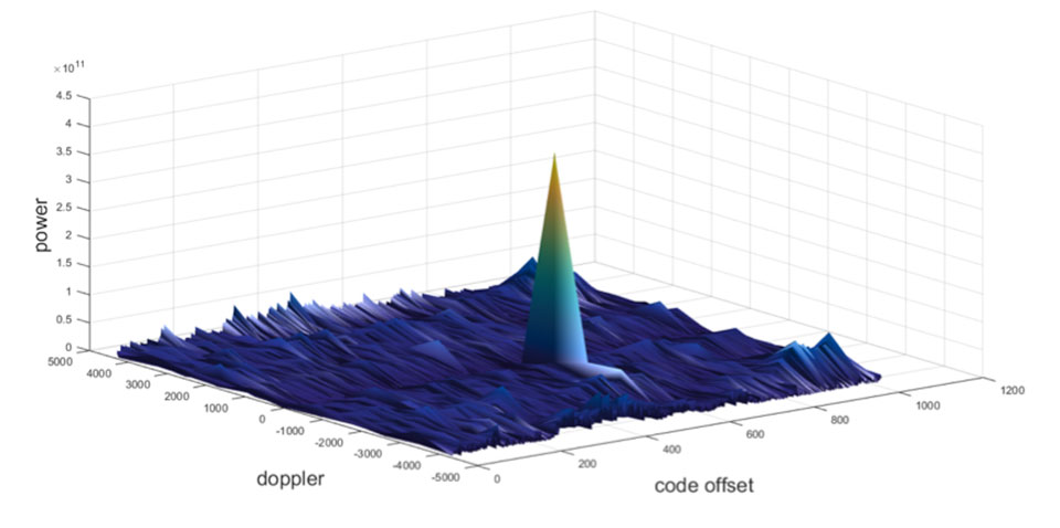
Let’s take a quick look at what it means to spoof GPS. A receiver searches for a satellite over a two-dimensional surface to find a correlation peak, and it must examine a range of Doppler frequencies and code offsets. An example is shown in Figure 1. Once the receiver finds the peak, the satellite is acquired, and it will then track the satellite as it moves and can demodulate the navigation data message.
When a spoofer comes along, it tries to recreate this peak. By doing so, and usually with little more power than the real satellites, the receiver will begin to track the spoofed signal. Once the spoofed signal is being tracked, the spoofer can begin to manipulate reality by slowly modifying the properties of the signal.
Figure 1. GPS correlation surface. (Image: Michael Jones)
A poor spoofer doesn’t always align itself very well with reality, which essentially creates a second peak on the correlation surface. But a gullible receiver can still be fooled by this, and may lock on to false peaks.
The reality of spoofing and anti-spoofing
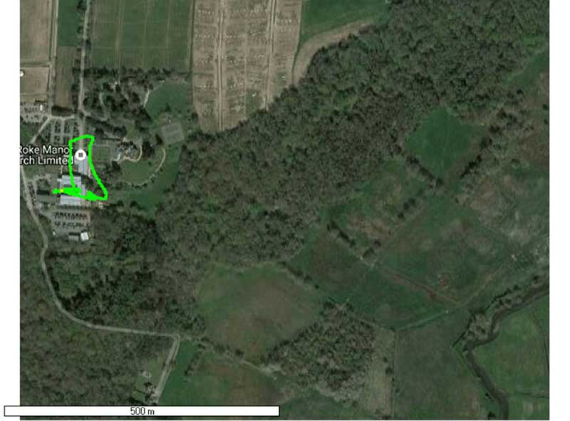
To understand the reality of spoofing and anti-spoofing, we carried out outdoor experiments at one of the Roke Manor trials areas (thanks go to my colleague Mike Wells for letting me use some of his results here).
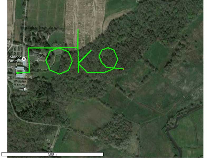
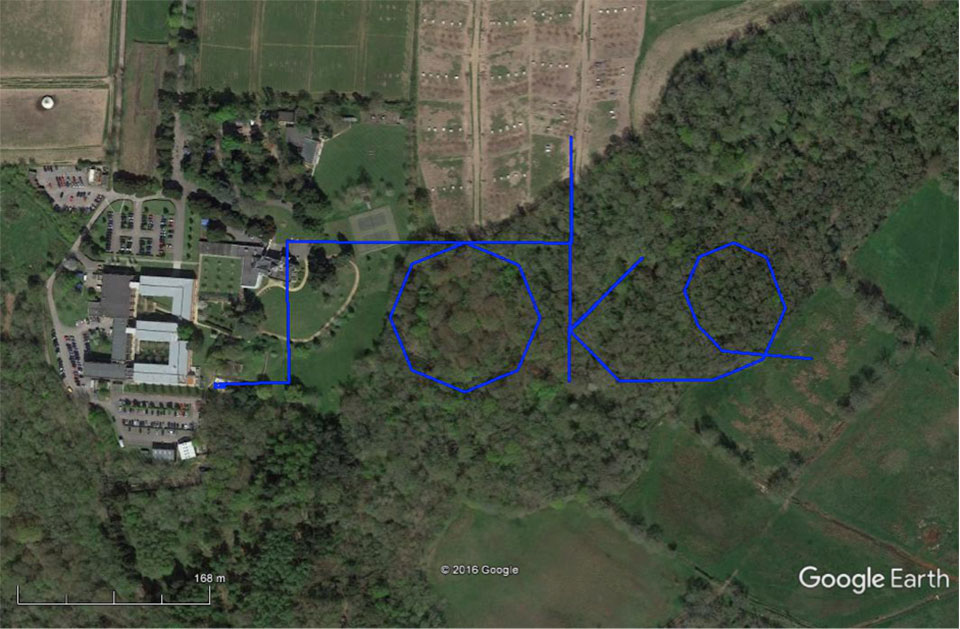
In the first experiment (Figure 2), we spoof a commercially available mass-market receiver. The receiver is outside, reporting its correct location at Roke Manor. When we commence the spoofing attack, we are able to take control of the receiver. Once captured, we can then make the receiver appear to follow an arbitrary course. Here we make it wander off into the forest, spelling the word “roke” as it goes.
Figure 2. Spoofed GPS receiver appears to follow a course, whilst in reality being stationary. (Image: Michael Jones)
In the next experiment (Figure 3), we place a conventional anti-jam antenna (a CRPA) on the receiver. What we observe, as you might expect, is that the basic CRPA offers no protection against the spoofing attack.
Figure 3. A GPS receiver is still successfully spoofed when protected by a conventional CRPA. (Image: Michael Jones)
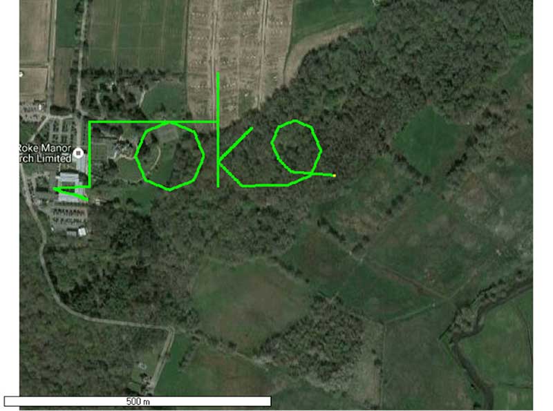
Now let’s make the experiment more interesting. We’ll move away from the basic commercial receiver, and replace it with a unit that contains not only a GPS receiver, but also a 3-axis accelerometer, 3-axis gyro, 3-axis magnetometer and a barometric sensor. An Extended Kalman Filter (EKF) performs an optimal fusion of the various sensors to yield the position solution.
The result, when we again try our spoofing attack, is shown in Figure 4. In short, the receiver is still successfully spoofed, despite the additional sensor inputs it offers.
Figure 4. A GPS receiver with integrated inertial sensors is still spoofed. (Image: Michael Jones)
Before everyone gets too depressed by the ease at which GNSS, and even GNSS fused with other sensors, can be spoofed, there are answers to this problem. Some decent, modern GNSS receivers contain a whole host of algorithms for detecting and ignoring spoof signals. The issue is that many legacy receivers are still in the field, and these can be extremely vulnerable indeed.
Another option is to use a more advanced CRPA, which offers anti-spoof capabilities. These adaptive antennas are able to correlate on the spoof signals, and then remove them based on direction of arrival. So, in our final experiment here, we use our commercial mass-market receiver again, and protect it with an anti-spoofing CRPA.
The result is shown in Figure 5. You can see that the receiver is briefly spoofed, and starts to wander off course. When the anti-spoof is enabled and kicks in, the position quickly drifts back to the true location and stays there. Good job.
Figure 5. With an anti-spoof CRPA, the GPS receiver detects the spoofer and quickly returns to its true location. (Image: Michael Jones)
Back to the Black Sea
Let’s finish by returning to the hot topic of the day. Did spoofing occur in the Black Sea back in June? Or was it a different form of interference? Could it have been a low-level jamming incident, causing the GPS receivers to report misleading information?
Without resorting to SIGINT (signals intelligence) data, and basing this discussion solely on public domain information and anecdotal evidence, I would say this was almost certainly a spoofing incident. A number of factors lead to this conclusion, and I’ll share some of them.
Firstly, it didn’t happen to one ship – it happened to over 20 separate vessels. So it wasn’t a malfunctioning GPS unit; it was an external incident of some kind.
Secondly, a large number of ships in the area reported identical or very close locations. This is a symptom of a large-scale spoofing attack. If it was a low-level jamming attack, then any misleading positions reported by vessels would typically have some randomness to them.
Thirdly, ships reported that their positions would periodically “jump” from the true location to the incorrect location. Again, this is very typical behavior in some spoofing experiments: For various reasons, GPS receivers may temporarily lose lock on a spoof set of satellites, and then reacquire the real ones, and vice versa. This causes the characteristic random flipping between two well-defined locations.
If we accept that a GPS spoofing attack did occur, it brings us to the million-dollar question.
Who did the spoofing, and why?
What I’ll do here is a bit of a lightweight analysis exercise using public information and basic physics, and you can formulate your own conclusions.
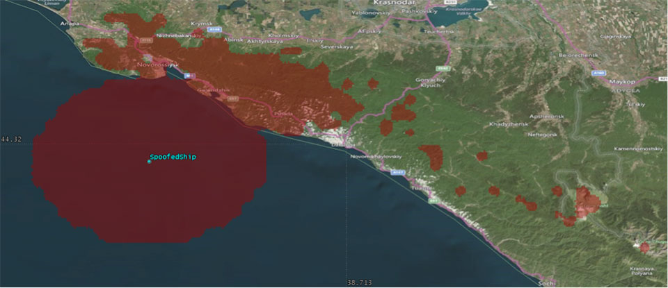
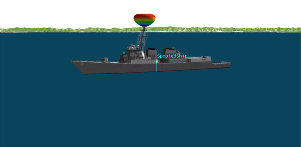
Let’s start by placing a ship, located in the Black Sea at 44°14.0’N 037°43.1E, which is the actual position of one of the reported spoofed vessels. For this example, I have placed a representative GPS antenna on the ship’s mast, with its antenna pattern shown.
Figure 6. Victim ship in the Black Sea, with GPS antenna pattern shown. (Image: Michael Jones)
To get a rough handle on the scenario, consider the possible propagation of the spoofing signal. As a first-order approximation, let’s assume a standard 4/3 Earth refraction model, with obstruction by terrain. That’s a reasonable assumption at this frequency: Any obscuration by terrain will block the spoof signal. Let’s also initially assume that our GPS antenna on the ship is mounted 38 meters above sea level, and our spoofing equipment is mounted on a mast 20 meters aboveground. From this information, we can plot a map of possible spoofer locations for this particular incident (Figure 7).
Figure 7. Possible spoofing source locations. (Image: Michael Jones)
The first thing we might conclude from this is that the spoofing indeed originates from Russian territory, close to the Black Sea coast. To spoof the ship from further afield would require a much higher antenna, or even an airborne antenna. Which, of course, is possible, but then we would also expect vessels over a much wider area to report interference.
To me, it’s fairly conclusive that spoof GPS signals are being transmitted from this area, to make GPS receivers in the area think they are at an airport. The final question is: “Why would someone do this?” To answer this question, we must resort to educated speculation. Why would you want to spoof GPS receivers into thinking they are at an airport?
There’s one explanation that fits very nicely: drone defense. Many drones, especially those operated by casual users, have geofencing rules that prevent flights over airports and other restricted areas. So, if you were trying to perform aerial surveillance of the Russian border, your drone may suddenly think it was over an airport, and take action accordingly. The action taken depends, of course, on how the drone is programmed, but often includes “land immediately” or “return to launch point.” Certainly some of the drones we operate will immediately attempt to land if they find themselves in restricted airspace.
So if your drones are falling into the sea, you now have one idea why.
In a technical report titled GPS Vulnerability released Sept. 15, the Alliance for Telecommunications Industry Standards (ATIS) renewed its call for an eLoran system to support telecom and other critical infrastructure in the United States.
As part of its “Recommendations to Assure Time for Telecom” the report says:
“An eLoran system (or equivalent) should be developed and implemented in the U.S. to provide a near-term alternative to GPS for the telecom system and other critical infrastructure. The physical and cyber security of eLoran transmission stations should be a consideration in their operation.”
ATIS termed its report “a major resource to help better understand and address a formidable telecommunications industry challenge: the vulnerabilities in the Global Positioning System (GPS).”
Requirements for precise time delivery have driven the industry toward the increased use of GPS and GPS-dependent technologies, it says. Yet this dependency has left the industry vulnerable to disruptions and manipulations of the GPS signal.
GPS Vulnerability (ATIS-0900005) provides insight into the sources of the most common problems with GPS and their impacts. The report also covers several mature proposed solutions that would satisfy telecommunications sector timing requirements.
“GPS disruptions have economic, financial and service impacts to carrier network operators, suppliers, cellular services as well as adjacent industries and government agencies that depend on a functioning wireless communications sector,” said ATIS President and CEO Susan Miller. “We believe that our report on this topic will contribute to solutions to help secure the delivery of time — a function critical to many sectors in our economy.”
Known vulnerabilities to deliver GPS time to a system include environmental phenomena, malicious interference and spoofing, incidental interference, adjacent band interference, poor antenna installations and rare but present GPS segment errors.
GPS Vulnerability discusses techniques to address these vulnerabilities as well as alternatives to GPS timing, with the goal of mitigating GPS vulnerabilities for the timing receivers used in the critical infrastructure.
Alternatives covered in the report include Navigational Message Authentication on modernized GPS civil signals, atomic clock time holdover, sync over fiber, eLoran, WWVB, terrestrial beacons and more.
Putin shows taste for spoofing
For several days in June, more than 20 ships reported problems with GPS reception in the Black Sea (see Expert Opinion column, August GPS World). Experts concluded the problems were probably the result of a spoofing attack in the area.
Norwegian journalist Henrik Lied of NRKbeta compared this with accounts of similar episodes near the Kremlin complex in Moscow, where tourists have reported their smartphones showing them at an airport outside the city.
Lied interviewed University of Texas professor Todd Humphreys about his theory that this is an effort to keep drones from flying in the area: “Several of us [researchers in GNSS] have concluded the Kremlin spoofing was likely trying to trigger UAV geo-fencing, which prevents UAVs from flying near airports,” Humphreys said.
A Moscow correspondent for the Norwegian Broadcasting Company reports that these GPS problems only tend to occur when President Vladimir Putin is in town.
Several of the ships spoofed in the Black Sea were sailing in the vicinity of the Russian premier’s Black Sea vacation home. Putin was actually in the area when the incidents occurred. This may indicate that Russian authorities are spoofing wherever the Russian president is located.
Humphreys said, “It’s long been assumed that Russia, China and other nations (including the U.S.) have the technology to carry out a spoofing attack. What’s surprising is Russia’s willingness to use it openly and somewhat indiscriminately. It does fit nicely into what has been called Russian disinformation technology.”
Dana Goward President, Resilient Navigation and Timing (RNT) Foundation
An apparent mass GPS spoofing attack in June involved more than 20 vessels in the Black Sea and suggests that Russia may be aggressively experimenting with signal disruption and spurious substitution.
“GPS equipment unable to obtain GPS signal intermittently since nearing coast of Novorossiysk, Russia. Now displays HDOP 0.8 accuracy within 100m, but given location is actually 25 nautical miles off…”
Subsequent dialog with the ship’s master and examination of various documents and screen grabs he furnished enabled navigation experts to conclude this was a fairly clear case of spoofing: sending false signals to cause a receiver to provide false information. Other vessels in the vicinity experienced the same problem.
The RNT Foundation has received numerous anecdotal reports of maritime problems with the automatic identification system (AIS), a tracking system used for collision avoidance on ships, and with GPS in Russian waters, though this is the first well-documented public account.
Russia has very advanced capabilities to disrupt GPS. More than 250,000 cell towers in Russia have been equipped with GPS jamming devices as a defense against attack by U.S. missiles. And there have been press reports of Russian GPS jamming in both Moscow and the Ukraine. In fact, Russia has boasted that its capabilities “make aircraft carriers useless.”
The U.S. director of National Intelligence issued a report on May 11 that states that Russia and other actors are focusing on improving their capability to jam U.S. satellite systems.
Assuming Russia is behind this, why would they do such a thing? Possibly to encourage use of GLONASS or their terrestrial loran system, Chayka, instead of GPS. Possibly for some security reason known only to them.
Whatever the reason, it reminds us of the vulnerability of GPS signals, and of the plethora of motives that “bad actors” — governmental or private criminal interests — may have to disrupt and deceive GNSS users.
And of the U.S. Coast Guard’s advice about GPS and all satnav: “Trust But Verify.”
Dana Goward is president of the Resilient Navigation and Timing Foundation. He is the proprietor at Maritime Governance LLC. In August 2013, he retired from the federal Senior Executive Service, having served as the maritime navigation authority for the United States. As director of Marine Transportation Systems for the U.S. Coast Guard, he led 12 different navigation-related business lines budgeted at more than $1.3 billion per year. He has represented the U.S. at IMO, IALA, the UN anti-piracy working group and other international forums. A licensed helicopter and fixed-wing pilot, he has also served as a navigator at sea and is a retired Coast Guard Captain.
On April 6, Russia commissioned a new GLONASS ground station in Managua, Nicaragua — its first in Central America.
The station was created under a Jan. 26, 2012, agreement between the two countries to cooperate in the exploration and use of outer space for peaceful purposes.
GLONASS consists of 24 satellites orbiting at a medium height of 19140 km in three planes with inclination of 64.8 degrees. Access to navigation signals of GLONASS is provided to consumers across the globe free of charge and without restriction.
The station in Nicaragua is part of a global network that will monitor performance of all GNSS — GLONASS, GPS, Galileo and BeiDou.
Monitoring stations help ensure interoperability of the GLONASS system with other navigation systems and improves accuracy and reliability. It will also contribute to a precise global coordinate system, which is a key element of many international scientific programs, such as a global Earth monitoring program implemented by the International Association of Geodesy.
The information received by the station will be used for the Nicaraguan side of the self-control characteristics of navigation systems, refinement of its national system of coordinates, as well as for high-precision navigation services in order to improve the efficiency of agriculture, used in construction, aviation, navigation and scientific research.
The opening ceremony of the station was attended by a delegation of the government space state corporation Roscosmos, headed by the general director Igor Komarov, Russian ambassador to Nicaragua Andrew Buda, representative of the president of Nicaragua Laureano Ortega, and other officials.
“Our cooperation with Russia shows the kind of results we can achieve together in a short time, when there is the political will and technical capacity,” Ortega said. “This station is very important for Nicaragua and Central America as a whole. The use of the data will enrich all areas of industry and science of Nicaragua. ”
“The history of our cooperation in space activities has wonderful traditions, but today what we are doing together is a serious new step, important for modern society,” Komarov said. “In Nicaragua, the ground station will start operating GLONASS global navigation system, which embodies the most advanced technologies in the creation of navigation systems that will significantly improve the navigation performance of work on a global scale. This is the first GLONASS station in Central America, and it starts to work in Managua, which indicates the level of understanding of Russia and Nicaragua. “
At the 13th Group on Earth Observation (GEO) Plenary Meeting, representatives from GEO’s 103 member governments and 106 participating organizations convened to launch a new look for the Global Earth Observation System of Systems (GEOSS) Portal. The meeting was held Nov. 9-10 in St. Petersburg, Russian Federation.
Participants also addressed how best to advance GEO initiatives linked to its sustainable development goals and, for the first time, to engage with the commercial sector through a plenary panel session.
“Open data not only maximizes tax payers’ money in government infrastructure, it promotes economic growth, education and capacity building.” said GEO Secretariat Director Barbara Ryan. “GEO brings all sides of the conversation together so that data is broadly and openly available, free to the user and can be used to create value-added products and services to benefit society.”
The plenary meeting was held for the first time in the Commonwealth of Independent States (CIS) region. New member governments announced at the plenary were Uruguay, United Arab Emirates and Mongolia. Among the new participating organizations approved in 2016 are the European Association of Remote Sensing Companies (EARSC); the Humanitarian OpenStreetMap Team (HOT); the Integrated Carbon Observation System (ICOS); the Sahara and Sahel Observatory (OSS); and the World Health Organization (WHO).
The plenary opened with a message from the International Space Station. In the recorded video message, the cosmonauts observed it is easy to understand the interconnected nature of the planet. Space technologies help to understand Earth’s complicated processes and problems. Humankind is facing global challenges today, and international cooperation plays a crucial role in tackling these issues. The work of GEO makes Earth observations more widely available and meaningful, for the benefit of humanity.
https://youtu.be/C7nmvNb1z14
“We express our pleasure at the success of the GEO-XIII Plenary due to strong cooperation between the GEO community, Roshydromet and Roscosmos,” said co-host Alexander Frolov, head of Roshydromet. “Numerous side events organized by members and participating organizations clearly demonstrate the constantly evolving influence of GEO as an intergovernmental body.”
“Coordination of activities, and the joint harvesting and usage the data of Earth Remote Sensing (ERS) that was organized at the GEO-XIII Plenary is very relevant for all of the GEO community,” said Mikhail Khailov, deputy director general for Automatic Space Complexes of the State Corporation Roscosmos. “We are developing the technologies of ERS data processing and thematic services to benefit the people of the Earth through improved coverage, increased volume, quality and promptness of acquired ERS data.”
Philemon Mjwara, director-general, Department of Science and Technology, Republic of South Africa, reiterated the benefits of having access to EO data as an “enabling resource that allows us to begin addressing the Water-Food-Energy nexus, and other nexus, as a stepping stone to clearly understanding how the Earth’s systems work, and ultimately realizing GEOSS.”
“Downscaling implementation of GEOSS at national and regional levels has become extremely important to ensure broad engagement and sufficient resources to realize our ambitious vision,” said Pengde Li, deputy director general, National Administration of Surveying, Mapping and Geoinformation of China. “Fortunately, we see more and more members start establishing national inter-ministerial coordination and using regional initiatives as a vehicle for broad engagement.”
The Group on Earth Observations (GEO). The intergovernmental Group on Earth Observations (GEO) is comprised of 103 Member governments, and 106 Participating Organizations. Established in 2005, GEO strives to improve the world’s observation systems and provide policy makers and scientists with accurate and useful data that can be used to make informed decisions on issues affecting the planet. GEO’s primary focus is to develop a Global Earth Observation System of Systems (GEOSS) to enhance the ability of end-users to discover and access Earth observation data and convert it to useable and useful information. GEO is headquartered in Geneva, Switzerland.
On May 29 a Soyuz-2.1b with upper stage Fregat and a GLONASS-M satellite (No. 53) successfully lifted off from Plesetsk Space Center. The satellite was placed into its preprogrammed orbit and registered by the facilities of the Titov Main Test and Space Systems Control Centre. Ground control established communications with it. The stable telemetry link shows that onboard satellite systems are functioning normally.
According to Russian officials, an unexpected issue with the Fregat upper stage caused it to burn longer than planned to inject the satellite into its planed orbit. No further details were provided.
The satellite is destined for a replenishment mission of the GLONASS constellation, currently at 25 operational satellites. Russian plans call for as many as eight satellites to be launched by the end of 2017 to replenish the constellation. As part of that strategy, a Proton-M heavy carrier rocket with three GLONASS satellites aboard may take place by the end of this year.
Another GLONASS-M satellite, designed and built by a team of Information Satellite Systems – Reshetnev Company, has been delivered to the Plesetsk cosmodrome.
Accompanied by the company’s technical team and housed in a dedicated high-technology container, it was shipped to the Yemelyanovo Airport of Krasnoyarsk and then flew to the Plesetsk cosmodrome aboard a cargo aircraft IL-76.
At the cosmodrome, ISS-Reshetnev technicians will begin preparing the satellite for its launch, which is expected to take place in late May.
A GLONASS-M satellite was launched into orbit on Feb. 7 at 03:21 Moscow time from the Plesetsk Cosmodrome spaceport, reports the Russian space agency Roscosmos. The Russian Defense Ministry successfully launched GLONASS-M 51 (known as 751 in orbit) aboard a Soyuz-2.1b rocket with a Fregat upper stage.
Three and a half hours after lift-off, the satellite separated from the upper stage and ground control established communications with it. The stable telemetry link shows that onboard satellite systems are functioning normally.
According to the telemetry data received from GLONASS-M 51, the satellite is in good health. With all its mechanical subsystems successfully deployed, the satellite completed Earth and Sun acquisition. The Moscow-based System Control System and ISS-Reshetnev’s Information and Computation Center have begun satellite’s performance check-out.
Status of the GLONASS constellation, shown here, indicates that the satellite is now in the commissioning phase.
GLONASS-M 51 will replace a GLONASS satellite now operating three years past its design life.
Based on the GLONASS system’s stable operation, there has been no need to launch new satellites to augment the system, said the satellite manufacturer. The most recent launch of a GLONASS satellite was performed in 2014.
Eight GLONASS-M navigation satellites are being stored at ISS-Reshetnev Company awaiting launch.
GLONASS orbital grouping provides a solution to problems of global positioning in the interests of the Russian Defense Ministry and civilian users. Access to civilian navigation signals of global navigation satellite system GLONASS is provided to Russian and foreign consumers free of charge and without restriction.
A GLONASS-M satellite is launched in February 2016. (Photo: Russian Ministry of Defense)