Current state of the art multi-frequency GNSS receivers operate by receiving L1 first and then L5. L5-first is a viable answer to the call for more resilience in GNSS as is being discussed in government and technical circles to protect vital national infrastructure. It is suggested as part of “Toughening Category 4: Signal Alternatives” to protect, toughen and augment (PTA) the current GNSS systems described by Brad Parkinson’s article in the March 2022 issue of GPS World.
Paul McBurney
The need arises from attacks directed by bad actors on a large scale, such as electronic warfare, and on a more humane scale, by bad actors such as self-jammers and spoofers. On top of that, normal interference can cause desensitization and denial of service on GNSS receivers from myriad terrestrial and satellite communications.
The PTA plan presents the Denial Radius Reduction Ratio (DRRR) figure of merit and shows that a J/S increase of 15 dB produces a DRRR of 0.18. Whereas a receiver without this additional 15 dB of J/S could be denied fixing out to 1 km from a given transmitter, a receiver with an additional 15 dB J/S would be denied out to only 180 m from the same transmitter.
The improvement in terms of area is proportional to radius squared. The article identifies that the J/S capability is different among GNSS signals and the best performance is obtained with L5, mainly because it has the highest chipping rate. L1C has a code length of 10,230 chips, the same as L5, but it is spread over 10 msec and has the same chipping rate as L1 C/A.
There are currently 72 L5 signals between GPS, Galileo, BeiDou and QZSS transmitting the same physical layer features of 10.23 MHz chipping rate, 1 kHz overlay codes and higher transmit power compared to nearly all L1 signals with a 1.023 MHz chipping rate and lower transmit power. The combination of these features at L5 is close to achieving this 15 dB performance level over L1.
Unlike current hybrid receivers, L5-first survives L1 jamming. (Photo: Carkhe / iStock / Getty Images Plus / Getty Images)
One might conclude that the current start of the art of a receiver with both frequencies (aka, a hybrid L1+L5) has this resilience. However, the market does not currently offer the ability to directly acquire L5 signals overall use cases of GNSS assistance without first acquiring signals at L1. This means they can only achieve this resilience when the interference is encountered after acquiring and fixing at L1. As soon as the L1 is lost and the position and time uncertainty grow beyond the receiver’s capacity to autonomously search for L5 signals, the receiver is denied service at the interference level tolerable at L1. If you cut the receiver into L1 and L5 pieces, only the L1 side is capable of fixing autonomously. As noted by Dennis Akos et al. (“Testing COTS GNSS Receivers Using Only a Subset of Supported Signals,” ION JNC 2023), “support for several signals/frequencies provides integrity and robustness.” Specifically, “under jamming scenarios, signal diversity can allow a receiver to still generate an accurate position solution.”
Current receivers are not able to acquire L5 for reasons related to history, cost and power consumption. Historically, the promise of L5 accuracy was so attractive that it was added to legacy chipsets based on L1 even when it was only partially deployed. It was impractical at that time to require L5 acquisition when there were fewer L5 satellites than at L1. Cost and power are related to the fact that L1 receivers’ acquisition methods are sized to acquire the L1, E1, B1 and G1 signals. Memory and compute capacities, including the digital clock speed, are sized for slower chipping rates and hence shorter code lengths. At this performance level, conventional time domain correlation is adequate. Some receivers deploy frequency domain methods at L1 and achieve a lower cost and power than time domain methods with similar capacity. However, the L5 acquisition complexity with time domain correlation is 100 times more than L1 as its complexity increases with N2, meaning the cost and power to acquire L5 is out of reach. While using a time domain acquisition engine to acquire L5 may be possible for strong signals when the code and frequency search space is constrained for those signals, directly acquiring L5 with conventional methods would have serious shortcomings in many use cases.
Interestingly, the signal designers across all GNSS systems have cleverly designed the L5 signals so they can be easily acquired after acquiring their counterparts on L1. The L5 primary and secondary code is predictable based on learning the L1 primary code and navigation data bit phase. E5a and B2a primary and secondary codes can be predicted by learning the well-designed E1/B1 primary and secondary code phases that have the same total period: the combination of the 4 msec code lengths synchronous with 25 bits of secondary code are in phase with the E5a 100 msec overlay code. After an L1 fix with fine time, L5 can similarly be directly acquired easily with limited searching.
Join the Resilient Navigation and Timing Foundation for a reception with the President’s National Space-based Positioning, Navigation, and Timing Advisory Board on April 23 at The Antlers Hotel in Colorado Springs. The event begins at 6:00 PM. General David Thompson, U.S. Space Force (retired) will discuss his experience as the first Vice Chief of Space Operations, the state of GPS, and the future of PNT.
For more information and to RSVP, contact [email protected] by April 17.
Quickly prototype a GNSS interference detection and reporting system.
Implement an internet-based High Accuracy and Robustness Service (HARS)for GPS.
Relax export controls that currently restrict use of adaptive anti-jam antennas.
These are just three of the efforts the U.S. government is pursuing as a result of recommendations from the President’s National Space-based Positioning, Navigation and Timing (PNT) Advisory Board.
For 20 years the PNT Advisory Board has been providing the government independent expert advice about GPS and PNT.
Established by presidential directive in 2004 and administered under the Federal Advisory Committee Act by NASA, its charter has been regularly renewed. The charter provides that the board shall:
Be composed of experts from outside the United States government.
Seek input from state and local governments, industry and academia on developments in the application of space-based PNT technologies.
Evaluate national and international needs for changes in space-based PNT capabilities and assess possible trade-offs among options.
Provide independent advice and recommendations to the National PNT Executive Committee (co-chaired by the Deputy Secretaries of Defense and Transportation) on policy, system requirements, and program needs.
While “space-based” is in its name and charter, the board has long recognized that terrestrial assets also can play an important role in serving PNT users by augmenting, reinforcing, and complementing GPS. The use of complementary systems, for example, could help demotivate intentional jammers and spoofers and help safeguard users during any interference event. Thus, the board often considers a wide range of capabilities and systems.
The board also discusses policy, education, international relations and other issues important to the PNT community. As one board member commented, “Technology doesn’t exist in a vacuum. It is developed by, and intended to serve, people. If you don’t recognize that, you are missing most of the picture.”
The current board’s membership includes an impressive array of experts in PNT policy and technology. Its 29 members include a former governor, a retired admiral, three retired generals, GPS’ original chief architect, a former undersecretary, a former assistant secretary, three former presidents of the Institute of Navigation (ION), three international members and experts from across academia and industry.
Chaired by former Coast Guard Commandant Admiral Thad Allen, the board’s primary efforts are driven by its six subcommittees, reflecting a holistic approach to effective PNT:
Strategy, Policy & Governance
Protect, Toughen & Augment
Emerging Capabilities, Applications & Sectors
Education & Science Innovation
International Engagement
Communications & External Relations
While the subcommittees meet in fact-finding sessions to gather data, the PNT Advisory Board’s deliberations are public. Semi-annual meetings inWashington, D.C. and other locations may be attended by anyone, either in person or virtually. Announcements on the board’s webpage and in the Federal Register provide details before each meeting. By law, the minutes of each meeting are available to the public, and video recordings of meetings are normally posted as well.
Input from the public about PNT issues of concern is also welcome to inform the board’s current and future deliberations. Information on how to send input will be posted with the meeting announcement here.
According to board member Jeff Shane, former undersecretary at the U.S. Department of Transportation (DOT), the PNT Advisory Board is evidence of government at its best. “The very fact that the board was established underscores our government’s willingness to hear and consider the widest variety of views and input. It should be a source of optimism, and even pride, for the entire PNT community.”
National Space-based PNT Advisory Board
The next meeting will be from 9:00 a.m. to 6:00 p.m. MDT, April 24, 2024, and from 9:00 a.m. to noon April 25 at The Antlers Hotel in Colorado Springs, Colorado.Click here for information on a reception on April 23, featuring Gen. David Thompson.
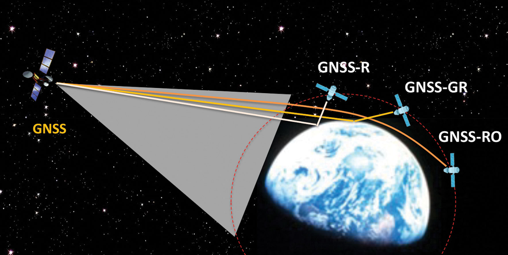
Figure 1: Scientific observations with GNSS radio occultation (GNSS-RO), GNSS grazing-angle reflectometry (GNSS-GR) and GNSS reflectometry (GNSS-R) techniques from low-Earth orbit (LEO). (Figure provided by the author)
Global navigation satellite systems (GNSS) for peaceful uses are facing a hard reality due to increasing regional conflicts in recent years. As a dual-use technology, GNSS for civil, commercial and scientific applications is vulnerable to both denied/degraded service and flex power operation from GNSS satellites and to jamming from the ground.
One of the vulnerable scientific applications is the use of GNSS receivers on low-Earth orbit (LEO) satellites that utilize the civil navigation signals for Earth observation. These remote sensing techniques, such as GNSS radio occultation (GNSS-RO), GNSS grazing-angle reflectometry (GNSS-GR) and GNSS reflectometry (GNSS-R) (see figure 1), are designed to observe weak GNSS signals either bounced off from Earth’s surface or refracted by the atmosphere. Thus, GNSS flex power operation and intentional radio frequency interference (RFI) can severely degrade the quality of the scientific data or even prevent Earth observation.
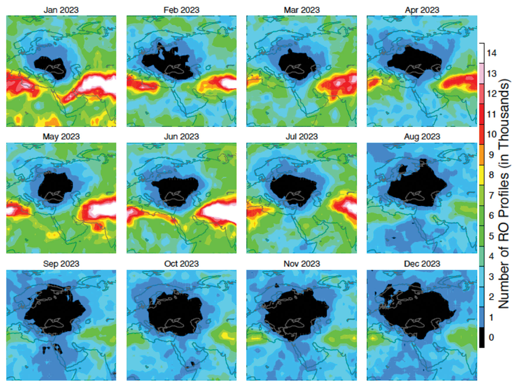
One example of such impacts is a dramatic decrease of GNSS-RO observations over Europe and the Middle East during 2023. Monthly statistics from Spire show the region without GPS-RO measurements grew substantially from the localized Ukraine-Russia conflict zone in January to a much wider area in Eastern Europe and the Middle East in December 2023 (see figure 2).
Figure 2: Number density distribution of monthly GNSS-RO measurements from the GPS tracking by the Spire constellation over Europe and the Middle East in 2023. The black area indicates no data. (Figure provided by the author)
This vast data void in the science observation is likely a result of the intensified electronic warfare used in Ukraine-Russia and the nearby conflict regions. The Spire RO receivers are configured to track the civil signals from GPS, GLONASS and Galileo. To increase signal protection against jamming in a conflict zone, GNSS service providers often use flex power operation. However, flex power operations can cause poor quality tracking with the RO receiver due to weaker signal power. Unlike a precise orbit determination (POD) antenna, the GNSS-RO antennas typically have a high gain to improve the detection of weak GNSS signals at limb and occulted views. However, if the transmitter power of civil signals drops below a quality-control (QC) threshold, the data are flagged as bad. This results in a poor coverage of Spire GNSS-RO in the conflict zones.
Lost or degraded GNSS-RO, GNSS-R and GNSS-GR observations are unfortunate, as these all-weather sensing, long-term stability, and high-accuracy measurements are becoming increasingly important in scientific research. GNSS-RO is a remote sensing technique that uses the GNSS-LEO link to profile Earth’s atmosphere and ionosphere with high vertical resolution. Since the first GNSS-RO six-satellite constellation, known as Constellation Observing System for Meteorology, Ionosphere and Climate-1 (COSMIC-1), these high-quality RO profiles have become a key data source for weather forecasting, climate monitoring, model evaluation, and space weather research. The current backbone of GNSS-RO observations comes from the COSMIIC-2 and Spire constellations, which have been producing more than 20,000 profiles per day since 2020. GNSS-R is a bi-static radar technique that uses the GNSS signals reflected by the surface for altimetry, ocean surface wind speed, wave height sea ice, soil moisture, and inundation measurements. At a view angle between GNSS-RO and GNSS-R, GNSS-GR can provide complementary measurements for sea ice and atmospheric column water vapor. Because of low-cost LEO SmallSat/CubeSat constellations with the GNSS receivers, geoscience studies have benefited greatly from the sampling density and coverage of these new data.
Civilization and science have been diverted by wars before. Despite the increased dependence on GNSS in recent years, their vulnerability to jamming and flex power operation poses a great challenge for scientific observations that need uniform global coverage.
The Russian satellite navigation system is experiencing tough times as Western sanctions and Russia’s ever-growing international isolation seriously complicate its further development.
Prior to Feb. 24, 2022, when Russia invaded Ukraine, Russia’s navigation sector was developing well and had a healthy growth rate, which is reflected by the steady growth and improved performance of its satellite constellations. However, the start of Russia’s war with Ukraine and the consequent international sanctions regime against Russia has put an end to the hopes for further development of the sector and especially of its flagship GLONASS global navigation satellite system (GNSS).
As for GLONASS, as academician Nikolai Testoedov, general designer of JSC Information Satellite Systems Reshetnev, one of Russia’s leading satellite manufacturing companies, said during a general meeting of the Russian Academy of Sciences, the main problem is that Western sanctions do not allow Russia to bring its positioning accuracy to the desired 30 cm or at least 50 cm.
According to Testoedov, the main reasons for this are serious problems with the supplies of electronic components, most of which Russia traditionally imported. “Until 2014, when the first sanction restrictions were introduced, the share of imports in Russia’s entire satellite constellations reached 42%,” Testoedov said. “Currently we implement a strategy of import substitution in the sector, which is designed until 2030 and involves a transition to 100% domestic products. As of 2014, we had 6,000 electronic components of foreign origin. Since 2014, a lot of work has been done to combine various equipment. Now, it is used in Russia’s satellite constellations.”
It has already brought some results. According to Ivan Revnivyh, head of the GLONASS department of the Russian space corporation Roscosmos, thanks to the new satellites that have been launched in recent years, the accuracy of GLONASS civil signals has increased up to 1.32 meters. According to Revnivyh, Russia plans to continue work in this direction as part of its existing federal project “Maintenance, development and use of the GLONASS system,” which intends to increase the accuracy of the signals up to 0.3 m.
Russia plans to continue to improve GLONASS’s accuracy until it matches that of other GNSS and meets International Civil Aviation Organization (ICAO) requirements.
“When landing a civil aircraft at unequipped airfields,” Testoedov said, “the signal should arrive with a delay of no more than 6 seconds, with an accuracy of no worse than half a meter.”
Despite the sanctions, Russia plans to continue to develop GLONASS. As part of these plans, starting from 2025, it plans to launch modernized GLONASS-K2 satellites in an import-substituted and multifunctional version. Thanks to this, the signal will be 100 times more powerful than the standard one. That will be primarily achieved by using dedicated navigation satellites weighing about 1 ton.
After 2030, Russia also plans to place six satellites in geosynchronous orbits (about 36,000 km), which will increase the availability of the signal in Russian cities and difficult terrains.
There are also plans to create a constellation of 300 satellites in low-Earth-orbit (LEO) at an altitude of 500 to 100 km. They are expected to increase the strength Russian satellite signals by more than 1,000 times.
In recent years, Russia has faced restrictive policies implemented by various international bodies, including the International Bureau of Weights and Measures and the International Association of Geodesy. According to Russian experts, many of these bodies are currently taking discriminatory measures against Russian systems and technologies.
In this regard, Russia plans to propose to the countries members of BRICS — an intergovernmental organization comprising Brazil, Russia, India, China, South Africa, Egypt, Ethiopia, Iran and the United Arab Emirates — to design products and systems whose characteristics will be comparable to those of Western origin. According to Reshetnev Systems’ experts, however, this could improve results — mainly, accuracy — by only 20 percent, which would not be critical for Russia.
GLONASS, which first achieved a full constellation of 24 satellites in 1995, currently consists of 24 satellites of three types: GLONASS-M, which has been produced since 2003, GLONASS-K which has been produced since 2011, and two GLONASS-K2, which Russia launched in 2023. All the satellites are part of the Cospas-Sarsat system.
Despite the fact that the life expectancy for most Russian GLONASS satellites is seven to 10 years, many of them, according to Testoedov, are already more than twice as old. Russia plans to replace at least six GLONASS satellites within the next two to three years. In the first years of launching the constellation, Roscosmos usually launched nine satellites into orbit at once; currently, it is launching only one or two at a time.
Still, it is possible that these rates will increase significantly, as by 2030 Russia plans to increase its constellation of satellites by up to 1,000 satellites. For this purpose, the country plans to produce 200-250 satellites per year.
According to the head of Roscosmos, Yury Borisov, space industry enterprises should produce one satellite per day by 2030. According to him, the Russian Federation is ready to learn from the experience of other countries in this area, such as China.
Figure 1: Utility access box installed over CORS reference mark Whitefish Pt A (NGS PID AA8050) at USCG lighthouse. (Photo: Jeff Olsen)
GNSS users who appreciate that physical monuments can provide verification of GNSS observations can do four things to preserve those monuments and make them more accessible. References below are to U.S. national agencies, but most countries have equivalent agencies.
Install a valve box over each buried control point recovered or set, whether the point is for boundary or geodetic surveying. Include National Geodetic Survey (NGS) deep-rod marks that have a buried logo cap.
Advocate with the Secretary of the Interior and United States Geological Survey (USGS) director that USGS scan its paper geodetic data sheets and post the scanned pdf files online.
Adopt the geodetic marks in your area. Visit them. Keep them free of brush or other blockages. Maintain descriptions and photos up to date by submitting recovery notes to NGS as needed. Participate in the NGS GPS on Benchmarks program.
Consider recovering all the marks in an NGS level line. Alternatively, all the USGS marks in a 15’ quadrangle, the geographic unit USGS uses to publish its geodetic data.
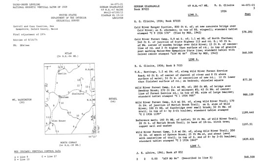
Figure 2: Example of USGS vertical data published by 15’ quadrangle.
Regarding the first of these actions, a valve box is a utility standard. It identifies to non-surveyors that there is something under the box to which one should pay attention, thus increasing the mark’s chances of survival.
The box lid is generally obvious, eliminating or at least reducing the search time for surveyors, who only need to walk up to the box.
It replaces the soil that previously covered the mark, reducing excavation time. A surveyor only needs to open the lid and brush off the mark. Rectangular and round boxes in several sizes are available to accommodate different-sized monuments. While the time and materials to install a box may be an overhead cost to your company, it is well worth the investment.
Regarding the second of these actions, the positions and heights published for most USGS control marks are based on superseded datums. However, that old data can be useful for evaluating trends. The marks are usually stable and can be reused in new projects.
While NGS has observed some of these marks and published datasheets for them, they are by far the minority of all the USGS marks in the country.
There are thousands of these sheets, 50 shelf-feet of them, organized by 15’ quad. Some sheets, mainly in the East, have been scanned and put online by various state agencies or utility companies. The USGS Rolla office has scanned most of the eastern states but has not posted the files online.
Generally, a request for USGS geodetic data turns into a request for paper sheets, such as those shown in Figure 2, to be scanned and emailed. Putting them online would preserve this record of what it took to survey and map our country, allowing the marks to be tied into new control surveys.
Earlier this week House Intelligence Committee Chair Mike Turner sounded an alarm about a serious national security threat. It had to do with Russia, a weapon, space, and something nuclear.
For many, these clues conjured up images of bombs falling to Earth from space, satellites destroyed by powerful electromagnetic pulses, shrapnel impacting the space station, and so on.
Yet, putting nuclear weapons in space would be a clear violation of the 1967 Outer Space Treaty to which Russia and the United States are both signatories. It would also significantly increase East-West tensions at a time when Russia has enough tension and international condemnation to handle.
Thursday evening the White House calmed the waters a bit by saying that Russia was pursing an anti-satellite weapon that cannot cause physical destruction on Earth.
The most reasonable conclusion to draw from all of this is that Russia is closing in on its goal of having a nuclear-powered electronic warfare capability in space.
Such a reusable weapon could be far more useful than any one-use nuclear explosive device.
“There is strong evidence from publicly available sources that a Russian company called KB Arsenal is working on a new type of military satellite equipped with a nuclear power source. Called Ekipazh, its mission may well be to perform electronic warfare [EW] from space.”
The author, Bart Hendrickx, goes on to explain that development of such a weapon would be entirely in keeping with reported Russian government plans. Citing one Russian language source he says:
“… the deployment of EW platforms in orbit would be in accordance with a policy for Russia’s electronic warfare program until 2020 approved by the Russian government in January 2012. A summary of this policy indeed mentions space-based electronic warfare as one of the objectives to be accomplished in the period before 2025. More specifically, it talks about the need to deploy ‘multifunctional space-based EW complexes for reconnaissance and suppression of radio-electronic systems used by radar, navigation and communications systems.’”
When intelligence agencies assess the severity of a particular threat, they look at an adversary’s desire or intent to carry out a particular act, and their capability to do so. If the reporting is correct, Russia has intended to put a nuclear-powered EW satellite or spacecraft in orbit for some time. This week’s political dust up may mean that the decades of hard work described by Hendrickx in Space Review have paid off and given them the ability to do so.
More Useful Than Orbiting Bombs
The United States is far more dependent upon space than any other nation. As regular GPS World readers know, this is especially true for the essential positioning, navigation, and timing services that underpin virtually every technology.
Destroying satellites would quickly lead to a shooting war that no one would want.
On the other hand, electronic warfare doesn’t necessarily lead to casualties right away and is harder to recognize as actual warfare. For example, Russia has been attacking NATO countries, ships, and aircraft in the Baltic with GPS jamming and spoofing on and off since mid-December. No one has died (yet) and NATO, to the best of our knowledge, has not responded.
Rather than destroying satellites, how much more useful is it to be able to temporarily disrupt the operation of one or more satellites? Or perhaps one type of satellite, such as GPS?
Such attacks are reversable, so the attacked party is less likely to send bombs and bullets in return right away. And if the attacker gets what they want, or suddenly discovers they have gone a bit too far and are approaching a kinetic exchange, backing off is as easy as flipping a switch.
Just the threat of being able to deny GPS or other satellite signals over a wide area would be useful.
In fact, Russia has already made this kind of threat and it didn’t backfire.
In November 2021, prior to its invasion of Ukraine, Russia used a ground-based missile to destroy one of its own defunct satellites. Shortly thereafter Russian state-sponsored media claimed the demonstration “… means that if NATO crosses our red line, it risks losing all 32 of its GPS satellites at once.” Aside from a strong diplomatic tongue-lashing, there were few consequences. Additionally, wherever the “red line” was, it seems that NATO did not cross it.
Nuclear Powered EW Most Likely
It’s hard to know what more will be revealed, if anything, about this week’s dust-up over Russia, weapons, space, and nuclear.
It is highly likely that Russia is executing its plans to extend this prowess and advantage into space with a nuclear-powered EW satellite.
Whether or not this is the root Washington’s kerfuffle, the possibility should be an on-going concern for the United States.
Our dependance on space makes us vulnerable. Our critical over-dependence on space for PNT, especially in light of the terrestrial PNT alternatives available to Russia and China, exposes our jugular and virtually invites attack.
We have placed most of our eggs in the same basket — and there are too many ways in which it can be knocked to the ground.
Until the United States establishes a resilient national PNT architecture, one with GPS at its center supported by other diverse and robust sources, we will continue to unintentionally encourage such things as space-based nuclear-powered electronic warfare and be at severe risk.
The National Geodetic Survey (NGS) has announced that users have until February 29, 2024, to submit data for the initial National Spatial Reference System (NSRS) modernization rollout. This means time is running out to submit GNSS or leveling data for initial NSRS Modernization. It is anticipated that NGS will release the new, modernized NSRS in 2025, once new data is incorporated into the database. The following newsletter will provide some advice on strategically selecting marks to improve the local accuracy of the NAVD 88-to-NAPGD 2022 transformation tool.
Image: NGS website
As the announcement stated, NGS is in the process of compiling, organizing, and cleaning all the relevant GNSS and leveling data contained within the NGS Integrated Database and the OPUS shared solutions database for preparation of the new, modernized NSRS. The data will be used in national scale survey adjustments using NGS’ new software package called LASER (Least-squares Adjustments: Statistics, Estimates, and Residuals). The adjustments will compute the initial sets of geometric and orthometric reference epoch coordinates (RECs) on many existing survey control marks and CORS around the country. The definitions of RECs and survey epoch coordinates (SECs) are spelled out in NOAA Technical Report NOS NGS 67, NGS’s Blueprint Part 3. My April 2021GPS World newsletter highlighted the Blueprint Part 3 document, and my August 2022GPS World newsletter provided details on RECs and SECs. Using the results of the adjustments, NGS will produce a suite of models and tools that will enable users to access and work within the Modernized NSRS.
During the last several years, NGS’ GPS on Benchmarks program has been encouraging stakeholders and partners around the country to submit GNSS data to NGS on marks that they use. This will ensure that these marks will have updated RECs when the new system is implemented. Also, just as important, marks that also have North American Vertical Datum of 1988 (NAVD 88) heights will be used to improve the local accuracy of the NAVD 88-to-NAPGD 2022 transformation tool.
NGS’ plans include accepting user data, but after February 29, 2024, they will not include additional GNSS and leveling data for the initial REC national adjustment and for use in building the transformation tools. In 2018, I wrote a series of GPS World newsletters that highlighted NGS’ GPS on BM program (February 2018, April 2018, June 2018, and August 2018). At that time, the GPS on BM program was very useful in the development and implementation of the hybrid geoid model GEOID18. This newsletter will provide an update on the GPS on BM Transformation Program and provide some advice on strategically selecting marks to improve the local accuracy of the NAVD 88-to-NAPGD 2022 transformation tool.
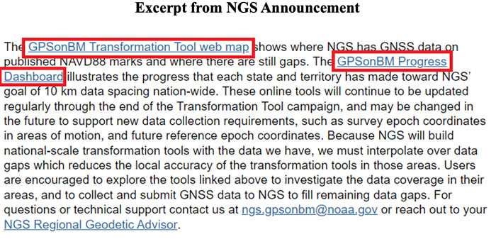
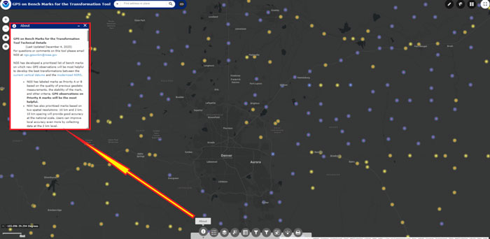
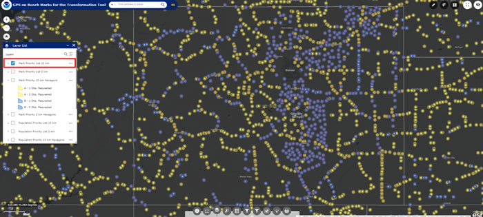
When users click the link GPSonBM Transformation Tool Web Map, they are connected to a web map depicting a prioritized list of marks where new GNSS observations would be most helpful to the development of the transformation model between the current vertical datum (e.g., NAVD 88) and the modernized NSRS.
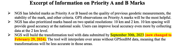
NGS’ prioritized list of benchmarks are labeled as Priority A or B. Clicking on the “About” button on the webpage provides information about the priority marks. See the boxes titled “GPSonBM Transformation Tool Web Map” and “Excerpt of Information on Priority A and B Marks.”
GPS on BM Transformation Tool Web Map. (Image: NGS website)
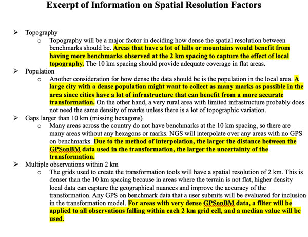
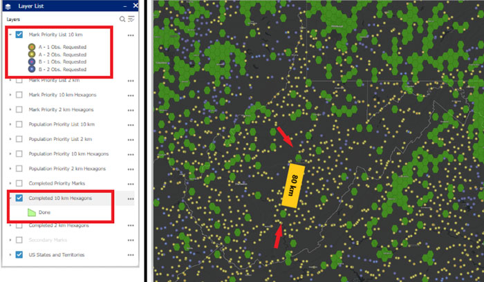
To assist users in their selection of marks, NGS developed criteria based on spatial resolution factors. See the box titled “Excerpt of Information on Spatial Resolution Factors.” As previously stated, time is running out. In my opinion, users should prioritize their GPS on BM plans based on the NGS’ criteria. I have highlighted what is important for users to consider when selecting marks.
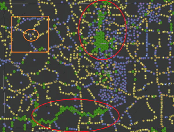
Many areas across the country do not have benchmarks at the 10 km spacing, so there are some areas without any hexagons or marks. As stated in the spatial resolution factors, NGS will interpolate over any areas with no GPS on benchmarks. In areas that have gaps larger than 10 km, that is, that are missing hexagons, I would recommend occupying several marks in each hexagon surrounding the gap to ensure that marks with valid NAVD 88 heights are part of the transformation tool. The web tool defaults to the Denver, Colorado, region when you access it but users can drag the map to an area of their interest or select a location.
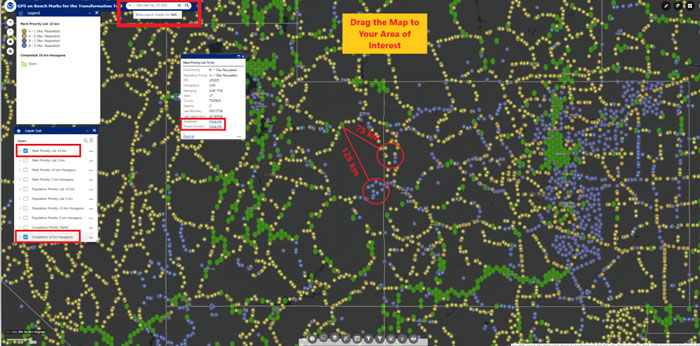
Locating marks using the GPSonBM transformation tool web map. (Image: NGS Website)
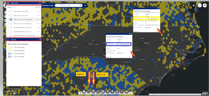
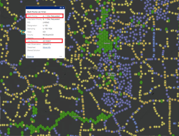
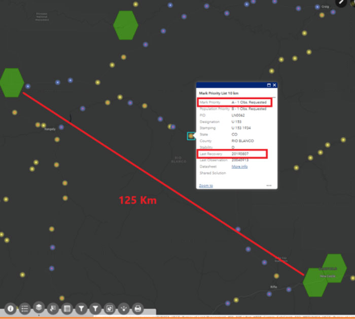
Acquiring data in mountainous regions and areas that have large distances between completed hexagons is probably the most important for users to focus on. The box titled “Locating Marks Using the GPS on BM Transformation Tool Web Map” provide marks that need to be observed. As an example, I have highlighted two areas that have large distances between benchmarks and completed hexagons. In this case, it would be important to occupy a couple of marks in the highlighted locations. Clicking on a mark provides a box with the following information: Mark Priority, Population Priority, PID, Designation, Stamping, State, County, Stability code, Last Date of Recovery, Last Date of Observation, Link to NGS Datasheet, and a Link to a Shared Solution (if one exists).
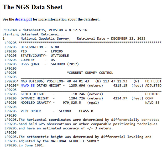
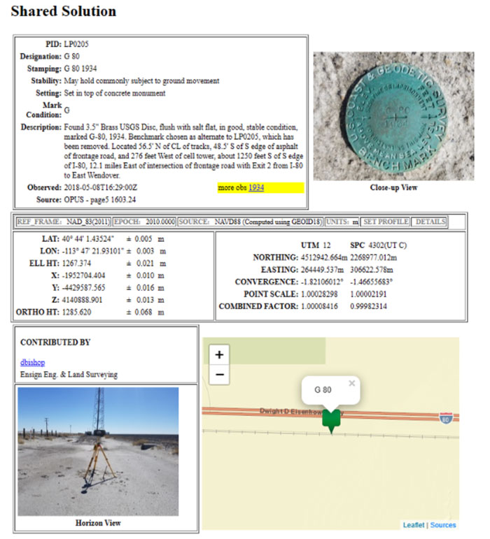
Clicking the link titled “More Info” next to Datasheet brings up the NGS datasheet for the mark, and clicking the link titled “More Info” next to Shared Solution” brings up the Shared Solution information (see the boxes titled “Mark Priority Information for Mark G 80,” “Excerpt from NGS Datasheet for Mark G 80,” and “Shared Solution for Mark G 80.”). I would recommend that State surveying organizations (and surveyors) perform this type of analysis and strategically occupy marks that fill in important gaps. There is less than two months remaining to submit data to NGS that will support the transformation tool.
Excerpt from NGS datasheet for Mark G 80. (Image: NGS website)Shared solution for Mark G 80. (Image: NGS website)
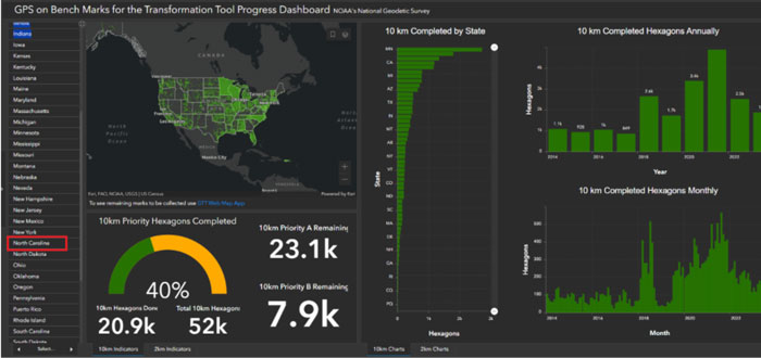
The GPSonBM Progress Dashboard illustrates the progress that each state and territory has made toward NGS’ goal of 10 km (and 2 km) data spacing nationwide.
GPSonBM Program Dashboard. (Image: NGS website)
Users can see the GPS on Benchmark information for a particular state by clicking on the name of the state on the left side of the website.
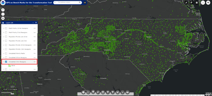
Selection of North Carolina. (Image: NGS website)
I highlighted North Carolina because I live in that state. The map informs the users of how many 10 km priority A (89) and B (32) marks are remaining to be occupied, and the percentage completed (92%). Clicking on the link “To see remaining marks to be collected use GTT Web Map App,” located under the map, depicts the remaining marks to be collected. As you can see from the plot, North Carolina has several marks in the eastern portion of the state that still need to be occupied with GNSS.
Status of GPS on benchmarks in North Carolina. (Image: NGS website)
A nice feature of the map is the legend and layer list buttons. Also, information about the mark appears if you click on a mark.
Example of legend and layer list. (Image: NGS website)
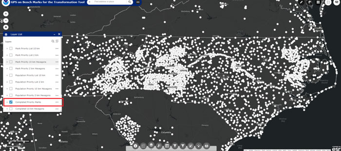
The image below provides a list of layers that can be selected using the webtool.
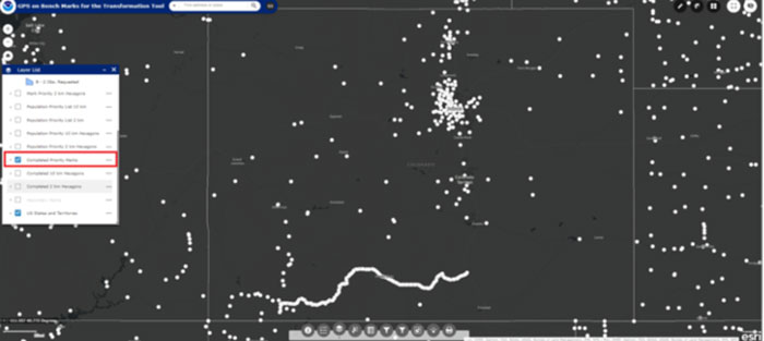
The following image depicts marks that have been completed. As you see from the plot, North Carolina has been very active in the GPS on Benchmark program.
Completed marks in North Carolina. (Image: NGS website)
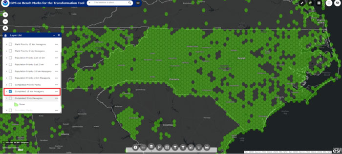
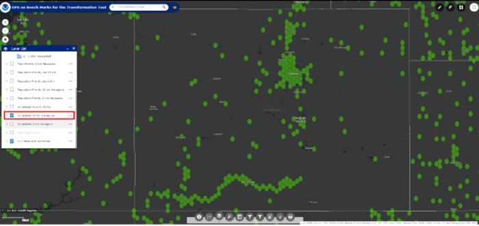
Users can also click on the button to see which 10 km (and 2 km) hexagons have been completed (see the boxes titled “Completed 10 km Hexagons in North Carolina” and “Completed 2 km Hexagons in North Carolina”).
Completed 10km Hexagons in North Carolina. (Image: NGS website)Completed 2km Hexagons in North Carolina. (mage: NGS website)
The North Carolina Geodetic Survey, under the leadership of Gary Thomson, along with NC surveyors has been involved with the GPSonBM program from its inception.
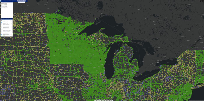
As previously stated, the website provides the list of priority benchmarks and the status of GPS on Benchmark for each state. There are other states that have been very active in the GPS on Benchmark program such as Minnesota and Wisconsin.
Completed 10 km Hexagons in Great Lakes Region. (Image: NGS website)
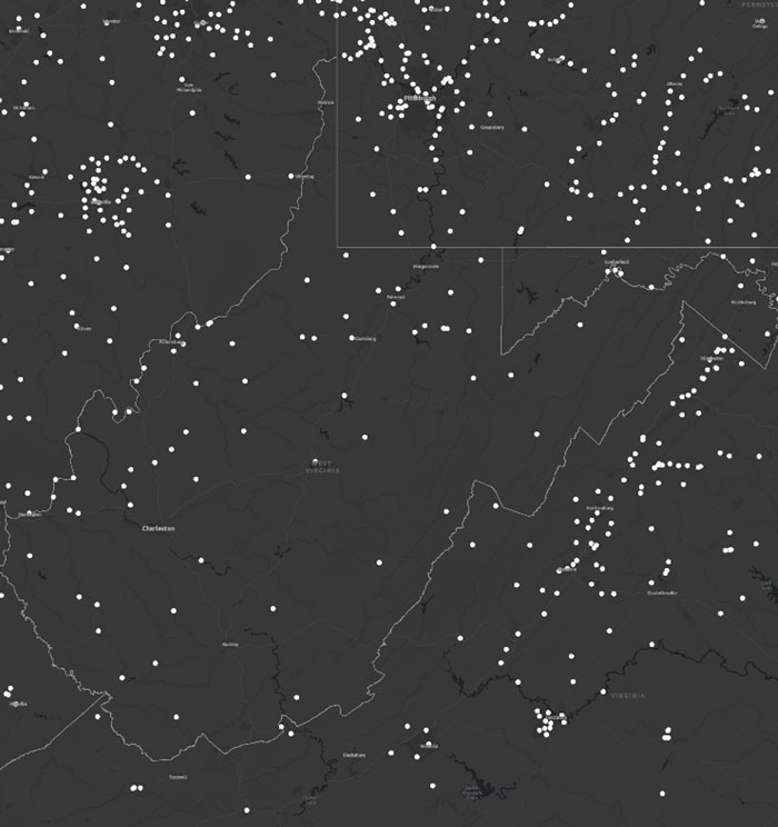
The following images provide the GPS on Benchmark information for West Virginia.
Status of GPS on benchmarks in West Virginia. (Image: NGS website)Completed marks in West Virginia. (NGS website)Completed 10 km hexagons in West Virginia. (Image: NGS)
The following image provides a plot of an area in West Virigina that highlights a region with a large gap between completed 10 km hexagons. If a user was interested in supporting the development of the transformation model in West Virigina, occupying a mark with GNSS in this area would help improve the local accuracy of the NAVD 88-to-NAPGD 2022 transformation tool.
Overlay of completed and status of benchmarks in West Virginia. (Image: NGS website)
North Carolina and West Virginia are not large states compared to some western states. The boxes titled “Status of GPS on Benchmarks in Colorado,” “Completed Marks in Colorado,” “Completed 10 km Hexagons in Colorado,” and “Overlay of Completed and Status of Benchmarks in Colorado” provide the information for Colorado. Looking at the plots there appears to be many regions that could use GPS on Benchmark occupations.
Status of GPS on benchmarks in Colorado. (Image: NGS website)Completed marks in Colorado. (Image: NGS)Completed 10 km hexagons in Colorado. (Image: NGS website)
Looking at the plot in the image below, there appear to be many marks that were occupied in populated areas such as Denver, Fort Collins, and Colorado Springs. The marks along the southern border were part of NGS’ 2017 Geoid Slope Validation Survey (GSVS) Project. The area highlighted by the orange box is an area that is lacking GPS on Benchmark occupations. The distance between the nearest completed 10 km hexagon is 60 kilometers. In other words, the two completed hexagons are more than 120 km apart. As previously stated, NGS will interpolate over any areas with no GPS on benchmarks.
Overlay of completed and status of benchmarks in Colorado. (Image: NGS website)
Again, in areas that have gaps larger than 10 km with missing hexagons, I recommend occupying several marks in each hexagon surrounding the gap to ensure that marks with valid NAVD 88 heights are part of the transformation tool. To demonstrate this concept, I have selected an area in Colorado near benchmark U 153 (PID LN0062).
Benchmark U 153 in Colorado. (Image: NGS website)
The following image depicts the locations of the completed hexagons near benchmark U 153.
NGS has developed web tools to assist users in the selection of marks for the program. Two web tools that I find useful are the Leveling Project Page and the Passive Mark Page. The Leveling Project Page provides information on leveling line data. Users can find information about the marks involved with a certain leveling line. There are links to the Passive Mark Page and NGS datasheets on the Leveling Project Page. My October 2020GPS World newsletter described the Passive Mark Page web tool in more detail, and my June 2021GPS World newsletter demonstrated the use of the tools.
In this example, I selected U 153 because it was located between two completed 10 km hexagons that are 125 km apart. That said, looking at the information from the passive mark web tool, it appears that the published height of the benchmark is based on 1934 leveling data. That by itself is not a bad thing but the Orthometric Height Residual is very large (-23.1 cm). This implies that the difference between the GNSS-derived orthometric height using Geoid18 and the published NAVD 88 height disagreed by 23.1cm. This could be due to the movement of the mark and, in my opinion, is not a good candidate for the transformation tool.
As previously stated, NGS’ Leveling Project Page, provides information on the benchmarks and associated data involved in a leveling line. See the box titled “Excerpt from NGS Leveling Project Page for L2577.” Users can find information about all the marks involved with a certain leveling line.
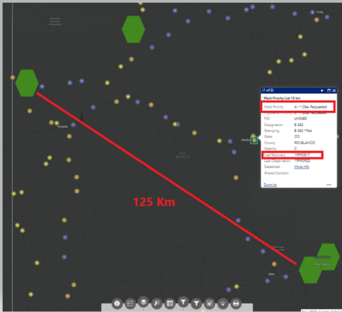
Excerpt from NGS Leveling Project page for L2577. (Image: NGS website)Distance between 10km hexagons near B 383 in Colorado. (Image: NGS website)
Again, I used the Passive Mark tool to find detailed information about the mark. See the box titled “Excerpt from NGS Passive Mark Tool for B 383.” This mark was last leveled in 1966 and the Orthometric Height Residual is small (1.2 cm). This implies that the difference between the GNSS-derived orthometric height using Geoid18 and the published NAVD 88 height disagreed by 1.2 cm.
This could be a good candidate for the GPS on BM program and the transformation tool.
Excerpt from NGS passive mark tool for B 383. (Image: NGS)
For completeness, I looked at another mark in the same area.
Distance Between 10km hexagons near B 154 in Colorado. (Image: NGS website)
I highlighted this mark because it was last leveled on the same 1934 leveling line as mark U 153. Unlike U 153, looking at the information provided by the Passive Mark tool for B 154 indicates that the GNSS-derived orthometric height agrees with the published leveling-derived orthometric height. The orthometric height residual is only -2.1 cm. This would be another good candidate to fill the area between the two completed hexagons.
This newsletter provided some advice on strategically selecting marks to improve the local accuracy of the NAVD 88-to-NAPGD 2022 transformation tool. Again, I would recommend that state surveying organizations and surveyors perform the analysis described above and strategically occupy marks that fill in important gaps. There is less than two months remaining to submit data to NGS that will support the transformation tool.
NGS has developed web tools such as Passive Mark Page and Leveling Project Page to assist users in identifying marks for inclusion in the development of the transformation model between the current vertical datums (e.g., NAVD 88) and the modernized NSRS.
It may be hard to remember — or imagine — life without the Global Positioning System (GPS). From finding the nearest Dunkin’ Donuts to making ATM withdrawals, GPS is part of everyday life. It makes global finance possible, first responders faster, electric grids smarter and industries more efficient. Without GPS, the critical infrastructure that powers homes and workspaces, mobilizes roads and rails, guides air travel, delivers news and even produces food could come to a grinding halt. That fact is not lost on the United States’ adversaries.
Modernizing GPS to make it work better in times of peace and to ensure its resilience in times of conflict is a prime responsibility of the Space Systems Command (SSC) of the U.S. Space Force (USSF).
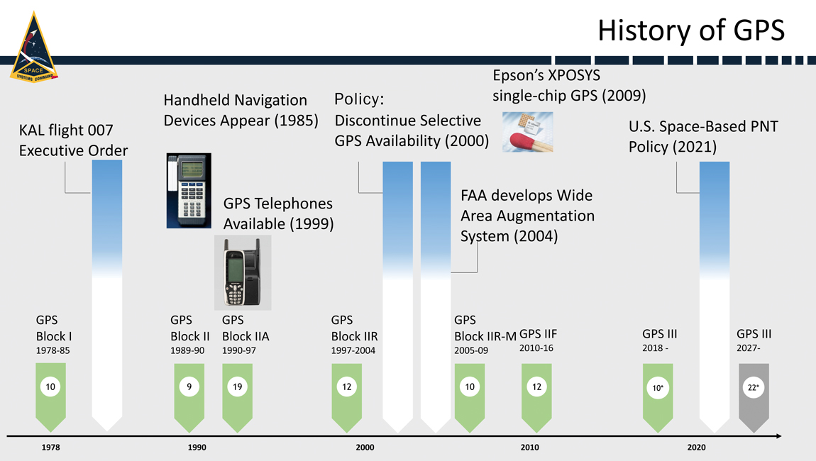
History
When it comes to anniversaries, 2023 is a big year for GPS. It’s widely considered to be the 50-year anniversary of GPS because it was on December 17, 1973, that the Defense Systems Acquisition Review Council (DSARC) gave U.S. Air Force Col. Bradford Parkinson, now retired and hailed as the father of GPS by many in the aeronautics and astronautics sectors, approval to proceed with development of what would become today’s 31-satellite GPS constellation.
It also marks 40 years since President Ronald Reagan authorized the use of GPS for civil aviation following the downing of Korean Air Lines Flight 007, after it inadvertently entered hostile air space. This year is also GPS’s 30-year anniversary of initial operating capability and the 20-year anniversary of the Federal Aviation Administration (FAA) Wide Area Augmentation System (WAAS), which enhances the accuracy and integrity of GPS services across the entire National Airspace System.
At the most recent meeting of the Civil GPS Service Interface Committee, the recognized worldwide forum for effective interaction between civil GPS users and GPS authorities, Parkinson — who, after his service in the U.S. Air Force earned a Ph.D. and has been a professor at Stanford University for decades — recounted his first-hand experience making GPS a reality. The former chief architect for GPS, who led original advocacy for the system as an Air Force colonel, described the incredible challenges and numerous unique innovations involved in starting this program.
Today’s GPS continues to deliver on its commitments for accuracy, integrity, availability, continuity and coverage. It is considered by many the gold standard in navigation and timing. Yet challenges remain, posed by an increasingly contested space domain and emerging threats from pacing challengers and adversarial nations. Advancing, maintaining and modernizing the GPS enterprise for the benefit of commercial, civil and military users falls under the responsibility of SSC and is carried out by the field command’s Military Communications and Positioning, Navigation & Timing program executive office (SSC/MilComm & PNT), in collaboration with its exceptional mission partners, and launch services provided by SSC’s Assured Access to Space program executive office.
As we celebrate the multiple GPS anniversaries, it is worth exploring successes in GPS modernization. This update will explore the exciting advancements in the GPS space systems, user equipment, and control systems.
Space Systems
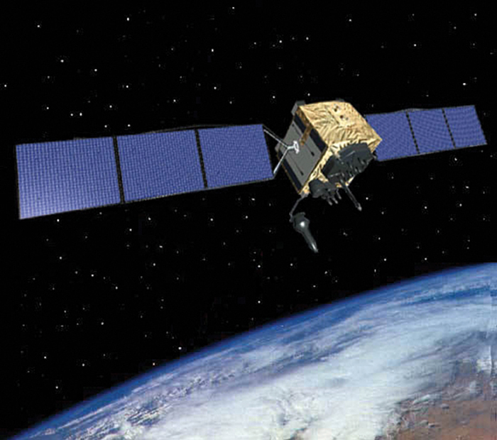
On January 18, the Lockheed Martin GPS III Space Vehicle 6 (SV06) launched into orbit aboard the SpaceX Falcon 9 Block 5 rocket out of Cape Canaveral, Florida. The successful launch of SV06 and handoff to the USSF’s Space Operations Command/Space Delta 8/2nd Space Operations Squadron marked another key step in the larger goal of modernizing the GPS constellation. SV06 is the sixth GPS III satellite to be launched and is equipped with the full suite of modernized signals and capabilities. The GPS III satellites are more capable and resilient than their predecessors. Improvements include three times greater accuracy and up to eight times improved anti-jamming capabilities.
In preparation for future launches, the GPS III team has been diligently working with the Assured Access to Space Launch Enterprise to ensure rigorous and successful integration of the GPS III spacecraft’s launch systems onto a brand-new rocket, the United Launch Alliance Vulcan Launch Vehicle. GPS III SV07/Vulcan is targeted for launch in the summer of 2024.
Additionally, production of the tenth and final space vehicle in the GPS III fleet was finalized this year and it has a target launch date of 2026. GPS III Space Vehicles 7-10 are in storage and available for launch, awaiting launch call-up.
The modernization, however, doesn’t end there. GPS IIIF continued to make progress this year with development and integration of the follow-on spacecraft program with 10 vehicles now in production. GPS IIIF Non-Flight Satellite Testbed completed panel integration and initial system performance testing and the program completed an integrated baseline review. The GPS IIIF team worked with the National Security Agency to successfully complete an information assurance preliminary design review, one of the first such reviews of its kind. The team has also made essential inputs to the planning for the future GPS IIIF launch and checkout capability.
GPS III Space Vehicle 06 (SV06) was launched Jan. 18 from Cape Canaveral Space Force Station in Florida. It is the 18th GPS satellite to broadcast the L5 signal.
User Equipment
SSC/MilComm & PNT actively manages and maintains the public GPS interface specifications that allow industry to build civil receivers that successfully capture and process the GPS signal-in-space satellite-broadcast. Simultaneously, SSC also leads design and development of military receivers, currently the Military GPS User Equipment (MGUE). In April, the MGUE Increment 1 team successfully completed technical requirements verification on its MGUE GPS receiver application module — a standard electronic module specifically designed for aviation and maritime users. This allowed the MGUE Inc 1 program to deliver its new aviation and maritime software to the U.S. Air Force and U.S. Navy to support the lead platform integration and testing on the B-2 Spirit bomber and the Arleigh Burke guided-missile destroyer. This is the first fully functional GPS aviation and maritime software suite to support the jam-resistant military M-code signal.
GPS has an active and successful foreign military sales (FMS) program with 60 allied partners, and many of them are highly engaged with SSC/MilComm & PNT to acquire MGUE receivers with their M-code capabilities. According to the Department of State, U.S. allies and partners purchase approximately $45 billion annually in arms, equipment, and training — many equipped with GPS — via FMS.
This spring, the MGUE Increment 2 team, developing an advanced, follow-on receiver, completed the new Next Generation Application-Specific Integrated Circuit (ASIC), the first of two major Critical Design Reviews (CDRs) with mission partner BAE Systems. That success was followed by a second CDR this summer for the MGUE Increment 2 Miniature Serial Interface (MSI) receiver card, which integrates the Next Generation ASIC along with a host of other innovations. L3Harris, a mission partner, has also successfully completed its own next generation ASIC CDR and is on-track for an MSI CDR in October. MGUE Increment 2 also awarded a Joint Modernized Handheld contract to the Technology Advancement Group, enabling this industry partner to move forward on its MGUE Increment 2 Handheld initiative.
Control Systems
While the current operational control system continues performing at a high level, a major update to the GPS modernization architecture is underway. In March 2022, the USSF began formal testing of the Next Generation Operational Control System (OCX) Block 1/2 system through the Functional Qualification Test designed to test OCX requirements. Currently, preparations are underway to follow that up with a major government-led Integrated Systems Test.
OCX developmental testing is an important part of the software development process. Thorough developmental testing can help ensure that OCX is of high quality and meets all requirements. Testing is rigorous and comprehensive; it is a complex and challenging undertaking, but one necessary to ensure OCX is ready for operational use before it is transitioned into service. SSC’s program office is taking the necessary steps to ensure that it will be a success.
The OCX 3F program also contributes to SSC’s advancements in GPS control systems. The follow-on to OCX for support to GPS IIIF spacecraft has successfully completed a Critical Capability Release for the GPS IIIF launch and checkout capability.
GPS IIF
Sustainment
SSC/MilComm & PNT’s GPS Support Delta has a legacy of providing sustainment expertise for Space Operations Command’s operations team. It sustains a global network including a Master Control Station (MCS), Alternate MCS, 11 command-and-control antennas, and 16 monitoring sites, plus 38 on-orbit GPS spacecraft. The sustainment team performs seamlessly, anticipating issues, collaborating with operators, updating servers and software tools, enhancing cyber secutiry and fine-tuning GPS to keep it running at peak performance.
Future Opportunities
In 2019, the department of the Air Force designated the Navigation Technology Satellite-3 (NTS-3) as a Vanguard program and the Department of Defense’s first experimental integrated navigation satellite system in nearly 50 years. Co-sponsored by SSC and the Air Force Research Laboratory, NTS-3 is helping to pave the way for more robust and resilient positioning, navigation, and timing.
In June, SSC/MilComm & PNT hosted its first Alternate/Augmented PNT Reverse Industry Day at SSC’s new Commercial Space Marketplace for Innovation and Collaboration Center. The event was a unique opportunity for government leaders and technical experts to hear directly from industry in a one-on-one environment about their many exciting innovations and opportunities as well as challenges. SSC was joined by its close government and interagency partners, including representatives from the Department of Transportation, the National Space-Based PNT Coordination Office, the Space Operations Command/Mission Area Team, the Air Force Research Laboratory, and the Space Development Agency. Through the event, SSC gained market intelligence and made many valuable industry connections for future investments.
Conclusion
As the nation celebrates an exciting 50-year anniversary of GPS, continued enhancements in the three elements of the GPS enterprise — space systems, user equipment, and control systems — represent significant milestones toward GPS modernization. This essential upgrade is delivering many new GPS capabilities — including robust new signals such as M-code, L2C, L5, and L1C — while preserving backward compatibility for GPS legacy signal users. GPS modernization will enhance utility, make the system more robust and resilient, and ensure that the United States, its allies, and its government agency partners have access to the most accurate and reliable navigation and timing services available. At the same time, while we continue to look for ways to (in the words of the National Space-Based PNT Advisory Board) “protect, toughen, and augment” GPS capabilities, we are also actively engaged in evaluating ways to incorporate alternate sources of PNT, as well as GPS augmentation, that will continue to make PNT capabilities even more robust and resilient in the future.
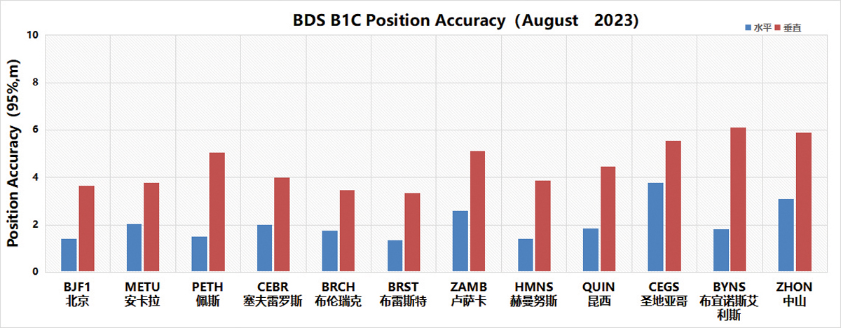
Figure 1. Global position accuracy of the BDS B1C signal (95%) Chart: Test and Assessment Research Center of China Satellite Navigation Office
Over the past year, the BeiDou Navigation Satellite System (BDS) has been continuously striving for world-class excellence throughout its development, especially in the system operation and the development of applications and new technologies. With this relentless innovation and pursuit of excellence, BDS continues to surpass its benchmarks.
System Operation and Services
The establishment of an on-orbit support system and the enhancement of on-orbit operational controls, combined with in-orbit software reengineering and real-time ground diagnostics, have significantly improved BDS’s functionality and service performance. Both space and ground segment operational statuses are regularly evaluated within the engineering framework. Various data sets and schemes are rigorously tested and reviewed to ensure the utmost level of user satisfaction.
In addition, the system integrates new techniques, such as joint satellite-to-ground and inter-satellite control, unified information transmission and coordinated processing of observation data. Combined with artificial intelligence, cloud platforms and big data analytics, the continuous global monitoring and assessment capability for BDS/GNSS has been upgraded.
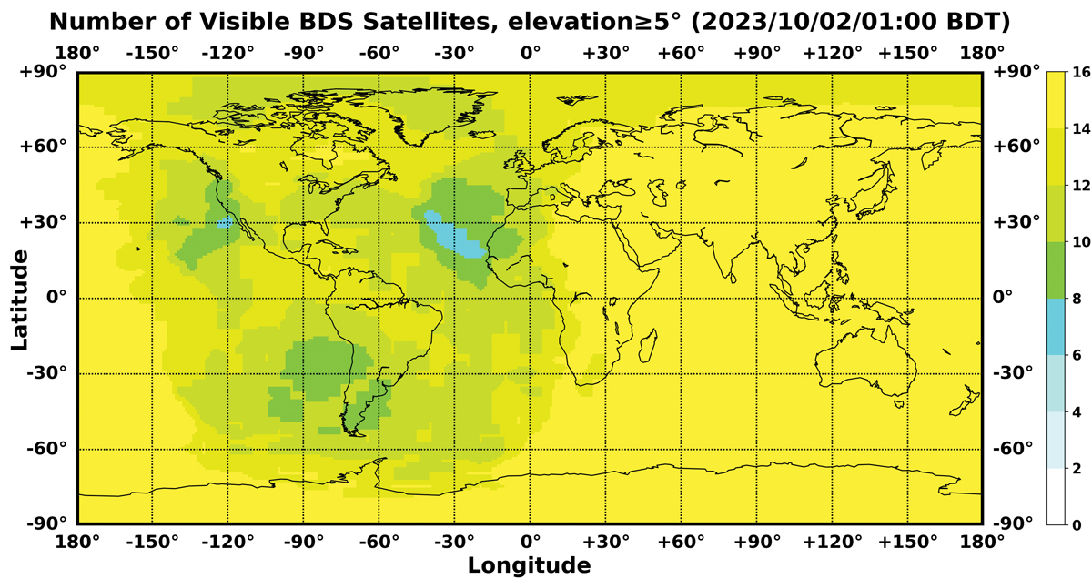
In May, the first BDS-3 GEO backup satellite was successfully launched. Currently, BDS operates a total of 46 satellites in orbit, comprising 15 in the BDS-2 constellation and 31 in the BDS-3 constellation. Since its official commissioning, BDS has been consistently providing reliable services with steadily improving performance metrics. Data from the International GNSS Monitoring and Assessment System (iGMAS) in 2023 indicate that the BDS space signal availability is 100%, signal continuity is 99.996%, and the global positioning accuracy is 5 m, with notable enhancement observed specifically within the Asia-Pacific region. Figure 1 shows the positioning accuracy of the BDS B1C signal assessed with global monitoring stations. Figure 2 shows the number of visible BDS satellites, with a minimum of six to eight satellites consistently in view globally.
BDS remains committed to serving the global community and benefiting humanity by promoting innovations that seamlessly integrate the fundamental positioning, navigation, and timing functions of the system, while building four major service platforms to support the development of BDS distinctive service applications. The International Search and Rescue Service Platform provides MEO search and rescue services that comply with COSPAS-SARSAT standards and offer BDS-based characteristic return link services. The satellite-based augmentation system (SBAS) service platform provides the single-frequency augmentation service using the B1C signal in accordance with APV-I requirements as well as the dual-frequency augmentation service using the B2a signal in accordance with CAT-I requirements. The short message service platform achieves seamless integration with terrestrial mobile communication systems and the Internet, marking a breakthrough in enabling smartphones to connect directly to satellites and bringing regional short message communication services to mainstream smartphone users. The ground-based augmentation service platform has a nationwide network of ground stations and provides high-precision positioning augmentation services in real time, with accuracy levels ranging from meters, to decimeters, to centimeters and even to millimeters for post-processing, to meet the needs of various industries and the general public.
System Applications and Industrialization
Xie Jun
The BDS application industry has experienced sustained growth. In 2022, China’s satellite navigation and location-based service industry reached a total output value of RMB 500.7 billion (approximately $71.5 billion USD). A complete industrial chain has been established, including chips, modules, antennas, boards, receivers and comprehensive services.
The basic BDS products have been continuously developed and have reached a production scale of hundreds of millions. In 2022, the sales of in-car navigation devices in China exceeded 12 million units. Sales of various receivers, including those for IoT, wearables, vehicles and high-precision equipment, exceeded 100 million units. Intensive research and development efforts are underway to integrate BDS navigation capability with inertial, mobile communication and visual navigation methods to enhance the user experience in various application scenarios.
BDS is extensively used in a wide range of sectors and is proving to be a key technological driver of socio-economic growth. In the transport sector, more than 7.9 million road vehicles, more than 40,000 postal and express delivery vehicles, more than 47,000 ships, more than 13,000 aids to navigation on waterways and nearly 500 general-purpose aircraft use BDS.
In agriculture, forestry, livestock and fisheries, more than 100,000 autonomous agricultural machine units, more than 20,000 intelligent livestock tracking collars and more than 100,000 fishing vessels are equipped with BDS receivers. In the water resource management area, the BDS Short Message Service supports hydrological monitoring of more than 2,500 reservoirs. In digital construction, the synergy of BDS with multi-sensor and Internet technologies has proven essential for projects such as the Chengdu-Kunming Railway, the Shenzhen Mawan Undersea Tunnel and the Xinjiang Desert Highway, significantly improving construction quality and efficiency while reducing labor and material costs.
Significant progress has been made in consumer applications. In 2022, 260 million of the newly registered smartphones in China supported BDS, accounting for 98.5% of the total. The BDS short message service has been seamlessly integrated into mainstream smartphones, eliminating the need to change SIM cards, phone numbers or add external devices. Consumers can now access BDS-3’s short message services. BDS-based lane-level navigation has been piloted in eight cities in China, with nationwide deployment planned. BDS-enabled features such as “Dynamic Traffic Light Countdown” and “Traffic Light Status” have covered millions of traffic signals in China, with daily signal queries exceeding 1.4 billion. Moreover, prominent domestic on-line mapping service providers deliver BDS satellite positioning service hits more than 300 billion times daily.
Figure 2. Number of visible BDS satellites Chart: Test and Assessment Research Center of China Satellite Navigation Office
International Cooperation and Exchange
China has strengthened bilateral partnerships to expand cooperation initiatives. In March 2023, the China-Russia Satellite Navigation Major Strategic Cooperation Project Committee was upgraded to the China-Russia Satellite Navigation Cooperation Subcommittee, which held its inaugural meeting in October. The fourth China-Arab States BDS Cooperation Forum was successfully convened in October. Active participation in international events under multilateral organizations such as the United Nations and academic exchanges in the field of satellite navigation have promoted joint discussions on global satellite navigation, ensuring the compatibility and interoperability of navigation satellite systems worldwide.
China has promoted the integration of BDS into international standards set by sectors including civil aviation, maritime, mobile communication, as well as search and rescue. In November 2022, the BDS Short Message Service System became the third global satellite communication system for maritime distress and safety, as recognized by the International Maritime Organization (IMO). In June 2022, the technical standards for BDS B2a and B3I signals were approved by 3GPP, leading to the formal release of BDS-assisted positioning standards for fourth- and fifth-generation mobile communication systems. In November 2022, China officially became a space segment provider for COSPAS-SARSAT.
Intensive efforts have been made to create an enabling “soft environment” through policymaking, standardization and IPR protection to maintain open communication and sustainable development. With the release of “The BeiDou Satellite Navigation Standard System (version 2.0)” in 2022, China has submitted more than 7,000 patent applications related to satellite navigation, underscoring its commitment to innovation and high-quality development. In November 2022, the Information Office of the State Council of China released a white paper entitled “China’s BeiDou Navigation Satellite System in the New Era,” which captures BDS’ transformative journey: unveiling new service capabilities, driving industrial growth, promoting collaborative initiatives and charting future paths.
In April, the 13th China Satellite Navigation Conference was successfully held under the theme “Digital Economy —Intelligent Navigation.” For the first time, challenges related to satellite navigation and positioning, navigation and timing (PNT) systems were solicited and later published on the official BDS website. These challenges cover current and emerging GNSS technologies, services and applications, including the establishment and maintenance of GNSS satellite-based spatial-temporal reference services, the provision of high-precision navigation and timing services in lunar space, the provision of accurate positioning services in complex environments, and the deployment of intelligent applications. In addition, proposals were made to develop a unified theory of multi-source heterogeneous spatial-temporal information for PNT applications, aiming to further integrate BDS, PNT and other new information technologies.
Prospects of Future Development
In the future, two to four backup satellites are scheduled to be launched to strengthen the robustness and accessibility of the BDS constellation. Commitments have also been made to continuously raise the standards of intelligent BDS ground operations and maintenance to ensure stable operation and performance improvement. In addition, system management and routine assessments will be strengthened, with a comprehensive strategy for both space- and ground-based operations to optimize the operational ecosystem and enrich BDS services and user experience.
In the area of emerging technologies, research on improving navigation with low-Earth orbit technologies, as well as its practical applications, will be further promoted to strengthen the precision and integrity of the system and to meet the requirements of an era characterized by ubiquitous connectivity and intelligent devices. Efforts will also include studies on multi-layer space constellations and the fundamentals of lunar space navigation to extend the coverage of BDS services. In addition, research will continue on satellite-based autonomous timekeeping technologies and pulse star technologies, with the aim of establishing and maintaining GNSS satellite-based spatial-temporal reference systems.
With the fundamental philosophy of “independent innovation, open integration, unity of all, and pursuit of excellence” in mind, the integration of BDS with innovative realms such as 5G, artificial intelligence, and big data will be accelerated steadfastly, aiming to shape a national PNT system that’s more ubiquitous, integrated, and intelligent by 2035.
The vast cosmic arena beckons for collaborative exploration. BDS will remain anchored to its mission. BDS is developed by China, dedicated to the world and strives to be first class. With a resolute ambition to promote progress, BDS strives to make significant contributions to the development of human society and a community with a shared future for mankind.
GLONASS remains a core of Russia’s positioning, navigation and timing (PNT) system and is utilized by people around the world. Annual shipments of new GLONASS/GNSS receivers for the communications, transport, agriculture and power industries exceed 25 million units in Russia alone. These users are interested in continuously increasing the quality of PNT primarily based on the improvement of the basic service radio navigation field generated by the GLONASS space complex.
This space complex consists of the constellation comprising medium-Earth orbit (MEO) satellites, the modernized ground control complex and the ensemble of user equipment. The current constellation consists of 26 satellites comprising three generations and five modifications. For the past 15 years, GLONASS-M has been the core satellite and now the constellation includes 21 of them. The fact that 14 of them successfully function beyond their guaranteed active lifetime verifies their high reliability. They are steadily being replaced with GLONASS-K satellites, of which there are already four in the constellation. Along with GLONASS-K launches, the in-orbit testing of the first GLONASS-K2 satellite was initiated on August 7, 2023.
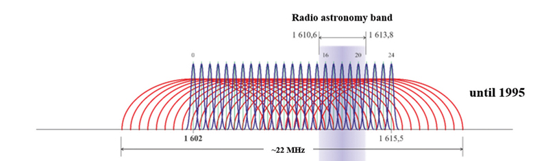
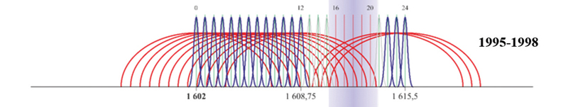
Since the launch of the first GLONASS satellite, the navigation signals have changed significantly. Initially, each of 24 GLONASS satellites transmitted the signals with its own separate carrier frequencies in the L1 and L2 bands (Figure 1). The total bandwidth of the registered GLONASS satellite network was 23.72 MHz in L1 band and 20.72 MHz in L2 band, respectively.
Figure 2. First phase GLONASS FDMA signals spectrum transformation in L1 band. Image: Sergey KarutinFigure 3. Second phase GLONASS FDMA signals spectrum transformation in L1 band. Image: Sergey KarutinFigure 4. Final GLONASS FDMA signals spectrum in L1 band. Image: Sergey Karutin
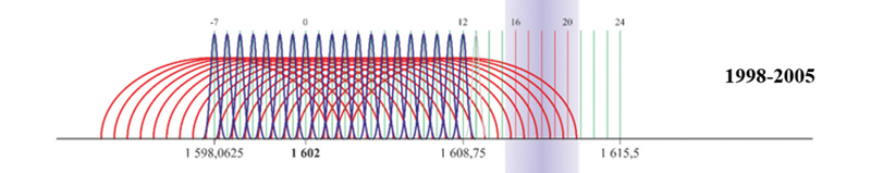
In 1995, the Russian Federation assumed obligations to protect the band used in radio astronomy in the search for extraterrestrial life. At the first stage (until 1998), the broadcast of the navigation signals in the carrier frequency channels 16-20 was terminated and the frequency channels 13, 14, 20 and 21 were used under exceptional circumstances (Figure 2). Then, all newly launched satellites transmitted the signals only in the frequency channels 0-12. By 2005, the total bandwidth of GLONASS satellites was reduced to 16.97 MHz in L1 band and 15.47 MHz in L2 band respectively (Figure 3).
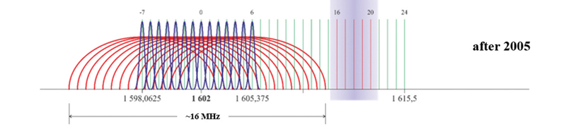
Starting in 2005, GLONASS satellites have been using the frequency channels from -7 to +6 (Figure 4) to broadcast frequency division multiple access (FDMA) navigation signals. As a result, the upper limit of the GLONASS signal bandwidth in the L1 band dropped from 1620.61 to 1610.485 MHz and the lower limit went down from 1596.89 to 1592.953 MHz. The signal bandwidth in L2 band changed similarly.
The GLONASS-K2 satellite was developed to improve GLONASS user performance. The satellite broadcasts new code division multiple access (CDMA) signals in the above mentioned bands as well as in the L3 band. The first satellite of this batch was successfully deployed in orbit on August 7, and already started to broadcast the new CDMA signals. The radio telescope of Bauman Moscow State Technical University is used to monitor the broadcast signals to analyze the frequency and power characteristics of the satellite.
The radio telescope has a large-aperture fully rotatable antenna with a dish diameter of 7.75 m. It ensures that the width of the main lobe of the antenna’s pattern in 1.6 GHz band is 1.8° and the power amplification of the received navigation signals is 40 dB.
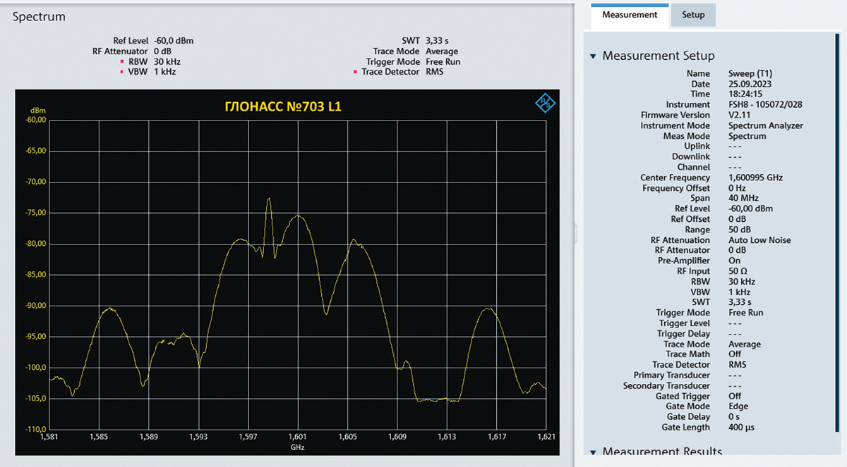
Primarily, users are interested in the new CDMA navigation signal on L1OC transmitted along with the conventional signal on L1OF. The joint group bandwidth of the FDMA signals with the carrier frequency 1598.625 MHz, which refers to the frequency channel -6, and the CDMA signals with the carrier frequency 1600.995 MHz is shown in Figure 5.
The exploitation experience of recently manufactured satellites in practice demonstrates that their operational capacity exceeds their planned lifetime by one and a half times. The final GLONASS-M satellite (No. 761) launched in the last year was manufactured in 2015. These circumstances make it possible to predict that the renewal of the whole constellation with new GLONASS-K2 satellites broadcasting the full ensemble of CDMA signals is likely to be finished by 2035.
In 2024, the renewal of the constellation will continue due to the launches of GLONASS-K satellites and another GLONASS-K2 satellite.
Figure 5. FDMA and CDMA signals spectrum in L1 band, broadcasted by first Glonass-K2 satellite. Chart: Bauman Moscow State Technical University
With the launch of the first GLONASS-K2 satellite accomplished, the Passive Quantum-Optical System (PQOS) is implemented on the base of Russian quantum-optical systems with a wavelength of approximately 0.5 nm. The PQOS ensures pseudorange measurements in the optical band. The elements of the system include specialized ground equipment to register moments of laser pulse emission by a ground laser station (ground PQOS) and specialized satellite payload equipment to register moments of the laser pulse reception onboard (onboard PQOS). Therefore, all GLONASS new generation satellites are capable of performing both conventional active (two-way) measurements and passive (one-way) measurements with the accuracy of timescale difference definition better than a nanosecond and based on the data of laser optical systems.
The processing of active and passive measurements gives an opportunity to get their difference combinations to compare timescales kept by onboard and ground frequency standards at a previously unachievable picosecond level of precision. The accuracy of PQOS results is sufficient to provide in-orbit tests of prospective new generation onboard frequency standards with a daily stability σ around 5×10-15.
The achieved accuracy level of PQOS results is also sufficient to calibrate measurement links for prospective GLONASS satellites, including links of active measurement systems, inter-satellite links and ionosphere-free linear measurement combinations conducted by passive measurement equipment based on FDMA and CDMA signals. The obtained results correspond to the world accuracy level in metrology and ensure the uniformity of measurements. The developed PQOS and technologies based on its measurements fully contribute to the effective metrological support for the tests and operation of the GLONASS space complex, including prospective GLONASS-K2 satellites and the ground complex.
BAE Systems has more than 45 years of military GPS experience. In fact, the first ever GPS signal reception on Earth happened at one of our offices in Cedar Rapids, Iowa, on July 19, 1977, when one of our legacy companies received the signal. Since that historic day, BAE Systems’ engineers have introduced more than 50 GPS products, including GPS anti-jam and precision landing systems.
As a pioneer in military GPS technology, BAE Systems has delivered nearly two million GPS devices on more than 280 platforms around the world. We design and produce advanced GPS technology compatible with the next generation M-code signal, improving security and anti-jamming capabilities for critical defense applications.
Can you share any recent innovations from BAE Systems?
BAE Systems innovates a full portfolio of M-code-compatible military GPS solutions to meet warfighters’ needs. Our Strategic Anti-jam Beamforming Receiver — M-code (SABR-M) is the most capable integrated anti-jam (AJ) electronics GPS receiver and the first integrated AJ M-code receiver available for weapons systems. It delivers assured, global position, velocity, altitude and timing, as well as strong protection against GPS signal jamming and spoofing — critical capabilities for unmanned aerial vehicles (UAVs), precision-guided munitions (PGMs), and missiles in threat environments.
This past June, at the Joint Navigation Conference in San Diego, BAE Systems unveiled NavGuide, a next-generation Assured Positioning, Navigation and Timing (A-PNT) device featuring M-code GPS technology. It is our response to strong defense market demand for a cost-effective, high performance handheld GPS upgrade. NavGuide provides an intuitive user interface and integrates easily into platforms currently using BAE Systems’ Defense Advanced GPS Receiver (DAGR).
How is your company preparing for the next 50 years of PNT with GPS and beyond?
BAE Systems is making advancements in our critical navigation capabilities for the warfighter through the Military GPS User Equipment (MGUE) Increment 2 program. We are developing a Next-Generation Application Specific Integrated Circuit (NG ASIC) for our small form factor Miniature Serial Interface (MSI) receiver. This will enhance our full portfolio of ground, airborne and weapons M-code assured GPS receivers beyond 2030.
We have invested an enormous amount of time and energy into our facilities and simulator capabilities, especially in our state-of-the-art simulators powered by Spirent Federal signal generation and RF wavefront technology. We want to be prepared to meet the technical demands of an ever-changing threat environment, and we need to be certain our receivers are prepared for the fight the first time, every time. We put our receivers through the paces by running them through thousands of trials on our Spirent simulators to validate and verify our performance under the most demanding scenarios.