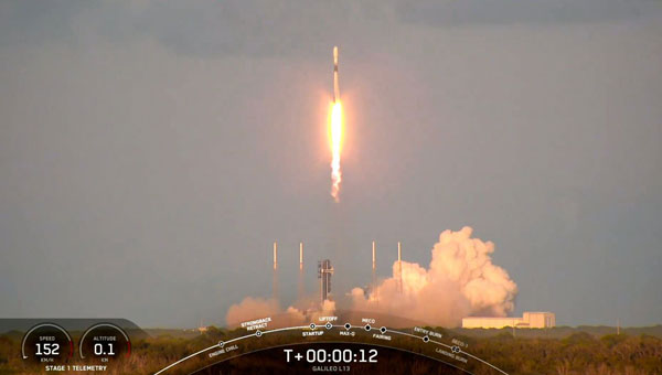
SpaceX has launched the latest pair of Galileo satellites from the Kennedy Space Center in Florida. The SpaceX Falcon 9 rocket carried satellites 31 and 32 (FM26 and FM32) to their designated orbits.
This launch, number 13 in the Galileo program, marks a crucial milestone in the constellation’s development. The addition of these satellites completes the designed constellation, with the required operational satellites plus one spare per orbital plane. The new pair will undergo testing at their final altitude of 23,222 km before becoming operational.
European Space Agency (ESA) Director of Navigation Javier Benedicto highlighted the importance of this launch, stating that the remaining six Galileo First Generation satellites are scheduled for deployment in 2025 and 2026.
These additional satellites are designed to enhance the system’s performance and reliability further, ensuring uninterrupted delivery of highly precise navigation services.
At ION GNSS+ 2024, Eric Châtre, head of EU GNSS exploitation and evolution at the European Commission, and Miguel Manteiga, Galileo project manager at ESA, participated in a panel titled “Status of GPS, Galileo, BDS, QZSS, KPS and NavIC.” They shared how 2024 has been a particularly eventful year for the Galileo program. In April, satellites 29 and 30 were launched and entered service in September. The new Public Regulated Service (PRS) signals began broadcasting, offering encrypted navigation for authorized governmental users. A significant upgrade of Galileo’s ground segment was completed without impacting users.
The Galileo system continues to evolve, with the development of Second Generation (G2) satellites underway. These satellites will feature fully digital navigation payloads, electric propulsion and inter-satellite link capacity.
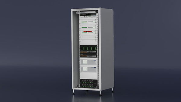
Adtranhas launched its Oscilloquartz Time Scale System, designed to meet the precise timekeeping requirements of national metrology institutes, scientific research facilities and other applications demanding the highest levels of accuracy and traceability.
The comprehensive system integrates Adtran’s Oscilloquartz grandmaster clocks, GPS/GNSS receivers, and high-performance optical cesium atomic clocks alongside a combination of the phase comparator, reference generator, and time interval counter. This ensures synchronization with coordinated universal time (UTC) and provides robust protection against cybersecurity threats.
With its customizable design, real-time monitoring, and seamless transition capabilities, the Oscilloquartz Time Scale System addresses the increasing need for resilient and accurate time synchronization across various sectors to ensure operational continuity and data integrity.
Leica Geosystems, a part of Hexagon, has introduced the Leica iCON trades solution, which includes the iCS20 and iCS50 sensors designed for construction layout tasks. This solution integrates with existing Leica iCON build portfolio tools, offering tailored workflows for construction industry users.
The solution features the Leica vPole, allowing free movement during measurements. It works with the iCS50 to lock to the vPole using a unique combination of dot and stripe patterns. This system can automatically detect pole height and compensate for tilt, facilitating accurate point and line layouts even in difficult-to-reach areas. These features are designed to increase efficiency and precision in construction workflows.
Leica iCON trades has Hexagon’s 6-degree of freedom (6DoF) technology, traditionally used in industrial measurement, to the construction sector. This seeks to broaden the scope of applications in construction, offering new possibilities for improving workflow efficiency and ease of use.
The solution is designed for quick and efficient layout tasks, leveraging artificial intelligence (AI) to tackle current industry challenges. Features include computational photography for advanced imagery and realistic site documentation, while AI capabilities predict pole movement to enhance target lock and tracking, thereby streamlining the layout process.
Rx Networks, a GNSS data services provider, has released TruePoint | LITE, a correction service designed for power-conscious applications that require precise and reliable location data.
TruePoint | LITEaims to deliver sub-meter and lane-level accuracy with global coverage for low-power usage. It is engineered with power efficiency in mind, focusing on applications such as smartphones, wearables, asset tracking and Internet of Things (IoT) devices.
TruePoint | LITE uses patent-pending predictive technologies designed to reduce dominant GNSS ranging errors—including ionospheric, orbital, and clock errors—to ensure accurate GNSS positioning while minimizing data traffic and conserving battery life.
TruePoint | LITE leverages proprietary predictive technologies to correct key GNSS ranging errors, particularly ionospheric range errors, according to the company.
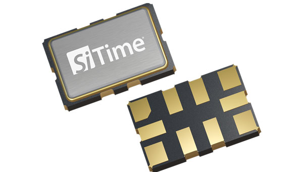
SiTime has launched the Endura Low Phase Noise Super-TCXO time synchronization and RF systems designed for high-performance applications requiring stability and low noise in challenging environments.
These devices operate within a frequency range of 10 to 220 MHz and offer frequency stability, with specifications as tight as ±0.1 ppm over a temperature range of -40°C to 105°C. Their phase noise performance can achieve -159 dBc/Hz at a 10 kHz offset for a 19.2 MHz carrier frequency and reach -172 dBc/Hz for broad base phase noise.
The Endura Super-TCXOs exhibit an acceleration sensitivity of 0.01 ppb/g and can withstand shocks up to 30,000g and vibrations up to 70g, making them suitable for demanding applications.
These Super-TCXOs are ideal for various applications, including time synchronization and RF systems, aerospace and defense networking, communication systems and positioning, navigation and timing (PNT) applications.
The European Geostationary Navigation Overlay Service (EGNOS) has released version 3.6 of its Safety of Life (SoL) Service for Aviation Service Definition Document (SDD), introducing several critical updates to enhance EGNOS satellite navigation-based operations.
SDD v3.6 describes improvements in EGNOS architecture for the space and ground segments. For the space segment, the document presents the latest technical information on the geostationary (GEO) satellites that deliver EGNOS services. In the ground segment, the ranging integrity monitoring station (RIMS) network has been expanded to include a new site in Kuusamo, Finland. The addition of this station in the far northern reaches of Europe extends coverage and heightens the robustness of SoL service in this remote and challenging environment.
SDD v3.6 also provides a detailed analysis of the impact of ionospheric activity during Solar Cycle 25, which began in December 2019 and is expected to peak around 2025. This extreme solar activity poses challenges to satellite navigation, and the document offers insights into how EGNOS maintains reliable performance under adverse ionospheric conditions.
The new updates aim to improve the precision, reliability and safety of satellite navigation services in aviation. The SoL service supports various transport domains, primarily focusing on civil aviation, covering localizer performance with vertical guidance (LPV) procedures.
OneWeb Technologies has launched Astra, which is designed to maintain low-Earth orbit (LEO) SATCOM connectivity in GNSS-compromised environments.
The package includes a software-defined outdoor receiver that leverages assured positioning, navigation and timing (A-PNT) broadcast services, significantly enhancing connectivity resilience. Astra can process PNT signals from GNSS and alternative sources across multiple frequency bands to offer continuous connectivity and situational awareness, even in challenging spectrum-contested environments.
The system is compatible with non-GNSS A-PNT broadcast services, such as Iridium. It can identify the optimal PNT source while producing an output signal compatible with the standard GPS L1 interface. In addition to its commercial applications, Astra aligns with the military’s Primary, Alternate, Contingency, Emergency (PACE) communications plan.
This is the story of two surveyors who met after retirement to accomplish two geodetic leveling projects in Maine and New Hampshire. Independent of each other, we had vacationed in those states, skiing and hiking. The idea of doing some geodetic leveling in that area appealed to us.
We first re-leveled parts of a 1942 Coast & Geodetic Survey (C&GS) line between North Conway, New Hampshire, and Gilead, Maine, to honor the surveyors of World War II. During summer trips, we looked for the benchmarks along the line, NGS archive L9971, and figured out which ones were missing. We set new marks as needed. Leveling took place between September 9 and 22, 2013, archived by NGS as L28096, Second Order Class II.
We used K&E Lovar yard rods — nice light wood rods with rod level, such as the U.S. Geological Survey (USGS) is believed to have used leveling up Mount Washington in 1925 — and a Zeiss Ni-2 level with 1:33 stadia interval (to convert yards to feet distance). Leveling up and over Hurricane Mountain Road NE of North Conway was a precursor to leveling up Mount Washington in 2014. We used a handheld GPS receiver to obtain the coordinates for marks that did not already have good accuracy. We obtained Online Positioning User Service (OPUS) coordinates for the reference marks on top of the mountain.
Leveling through the Mount Washington “cow pasture.” In the inset, MAC 100, one of the USGS benchmarks along the Auto Road. (Photo: Mike Pelchat, NH DNCR)
After completing the 2013 releveling of the 1942 C&GS line, we wondered about releveling the 1925 USGS line up Mount Washington. We approached the general manager of the Mount Washington Auto Road, Howie “Weems” Wemyss, explained what we proposed to do, and asked for his buy-in. He approved the project enthusiastically, allowing us full access to the road for the project. On May 12, we began the level run from first-order benchmarks in Gorham, New Hampshire, and finished on June 8.
Until this 2014 project, the elevations of Mount Washington were referenced to the National Vertical Datum of 1929 (NGVD 29) and were only available on paper from USGS. The professional purposes of the project were to connect Mount Washington to the North American Vertical Datum of 1988 (NAVD 88) and make the benchmark data available online from the National Geodic Survey (NGS). Two personal purposes were to continue enjoying the natural area and meet the challenges of the topography and weather.
Deciding where to place each level setup on the steep terrain involved a compromise between time spent trying to read at the very top of the rod and a quicker setup decision that usually sacrificed 1.0-1.7 ft of the rod. The maximum vertical gain on the 10-ft rod was typically about 7.5 ft per setup, sighting high on the lower rod while sighting on the upper rod above the yard equivalent of 0.5 m — thereby reducing refraction errors per recommended procedures. Sight lengths on the Auto Road were as short as 10 ft, averaging 30 ft. Along the less steep terrain of Route 16 between Gorham and the Auto Road, leveling between marks set by NHDOT, sight lengths ranged around 150 ft. Temporary benchmarks on boulders were selected between the MAC marks on the Auto Road to keep the number of setups in a section below 30. That way, if the forward and backward runnings of a section misclosed, it was not a hopeless number of setups to rerun and isolate the error. The grade between MAC marks was 14% in two cases, otherwise around 10%. To eliminate 1-yd reading errors, 1-ft markings were painted on the side of the rod and read to x.1 ft before the 3-yd readings (top, middle and bottom wires), then the foot and yard readings were compared. The typical elevation difference between a MAC mark and a TBM or between TBMs was 150 ft. The typical time per setup was 4.5 minutes, depending on how far apart the turning points were.
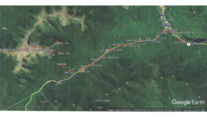
Project Diagram, 2014 Mount Washington leveling. ~8 miles SW along NH 16 from Gorham, 7.6 miles up the Auto Road. (Photo: Google Earth)
One bit of unwanted excitement occurred while the road crew was doing the annual rebuild of the 1-mile gravel section above Mile Post 5. The road workers pulled out the flagging at MAC 102, which is a bit hidden by vegetation. Evidently, it conflicted with the orange flagging they were also using. Leveling continued right past the disk for five setups until Bob noticed green paint on a boulder used as a turning point in the prior run. We had to reverse back to the mark. Fortunately, the section closed even with the extra setups.
There are some beautiful small waterfalls along the road that are easier to admire when you are walking by, not trying to keep your vehicle on the road. One day, we spotted a momma bear and two cubs. One man stopped to reminisce about his time working with Brad Washburn while Brad was doing extensive surveying and mapping on the mountain.
The USGS benchmarks are designated MAC 97 to MAC 104, “MAC” being the initials of the USGS party chief followed by a sequential number as the party progressed along the level line. There are lower numbered ones away from the Auto Road, and there used to be some higher numbered ones, which have since been destroyed.
The project data was accepted, adjusted and published by NGS as archive L28128. The elevation of the highest and most visited summit mark, Mount Wash Reset (DP4904), by the cairn and the brown park sign, dropped 0.77 ft, referenced to NAVD 88 compared to its elevation referenced to NGVD 29. The NGVD 29 elevation published by USGS (solely in feet), based on the 1925 leveling, was 6,288.176 ft (divided by 3.2808333 ft/m to obtain 1,916.634 m). These values were rounded off to 6,288 ft and 1,917 m, respectively, for display on the summit sign.
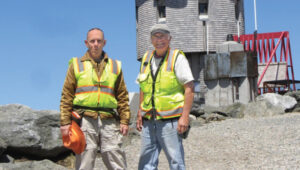
Jeff Olsen (on the left) and Bob Kunes in front of the observatory.
The NAVD 88 elevation for Mount Wash Reset, published by NGS based on this 2014 leveling, is 6,287.41 ft or 1,916.406 m. These values would round down to the next lower whole unit, changing the elevations that could be displayed on the park sign and making the mountain’s elevation lower. Since re-determining the mountain’s elevation was not a priority of this project, and a different elevation than the 6,288 ft that had been used for years would mean changing all those mugs, T-shirts and other tourist paraphernalia, we are not suggesting changing the elevation with which the public is familiar.
All the differences of elevation observed between the various USGS benchmarks agreed within Second Order Class II limits with the previous 1925 work. At that level of precision (section closures less than or equal to 8 mm multiplied by the square root of the distance in km), the 2014 leveling did not reveal or detect vertical motion on the mountain, after an interval of 89 years. The project could always be re-run with first-order equipment and procedures, cutting the section closure error budget in half to 4 mm multiplied by the square root of the distance. Various marks could be observed in a regional high-precision geoid modeling campaign.
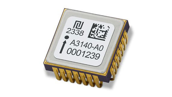
TDK Corporation has unveiled the AXO314, its latest addition to the Tronics AXO300 accelerometer platform. This digital MEMS accelerometer is designed for industrial applications operating under shock and vibration, with a ±14 g input range.
The AXO314’s closed-loop architecture provides linearity and high vibration rejection, offering a low-SWaP, digital alternative to tactical-grade quartz accelerometers.
It has a one-year composite bias repeatability of 1 mg and bias instability of 4 µg, offering a robust, miniature and precise acceleration sensing solution for dynamic systems in harsh environments.
This new accelerometer is well-suited for land, sea and air surveying and mapping applications and GNSS-assisted positioning systems for aerial and ground vehicles.
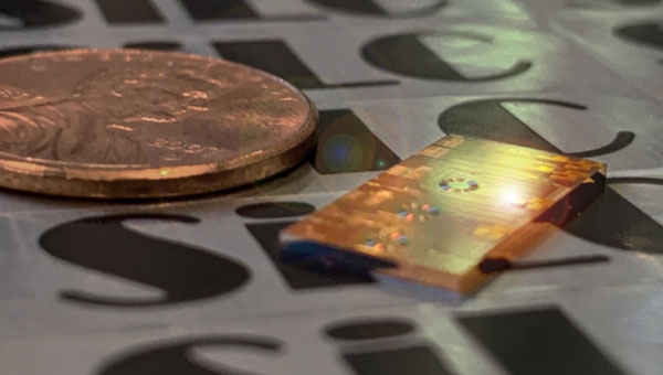
SiLC Technologies has received an investment from Honda to develop frequency-modulated continuous wave (FMCW) lidar solutions. This collaboration aims to advance artificial intelligence (AI)-based machine vision capabilities for autonomous vehicles and other mobility systems.
SiLC’s FMCW lidar technology offers long-range detection, precise measurements, interference resistance and enhanced object detection. It can detect objects at distances of a kilometer or more, offering accurate distance and velocity measurements while overcoming issues related to sunlight, reflectors and other lidar systems. Additionally, it can identify dark objects, such as tires, at long distances.
The investment from Honda supports the development of vision systems that are powerful, computationally efficient, compact, and scalable. These attributes are crucial for advancing autonomous transportation technologies that can enhance safety, reduce traffic congestion and minimize human error on the roads.
As a FMCW lidar developer, SiLC’s technology could play a role in advancing autonomous systems. The company’s Eyeonic Sensor and Vision System is an advanced lidar technology centered around the Eyeonic Vision Chip. This chip integrates multiple photonics functions, including an ultra-low linewidth laser, semiconductor optical amplifier, Germanium detectors and optical circuits on a silicon photonics chip. This compact design enables long-range detection of more than 2 km with sub-millimeter resolution, offering capabilities such as distance measurement, instantaneous velocity, and polarization intensity through FMCW lidar technology.
Advanced Navigation, Hanwha Aerospace and Hanwha Defense Australia (HDA) have signed a memorandum of understanding (MoU) to co-develop strategic grade assured positioning navigation and timing (APNT) solutions.
Under the agreement, the three companies will collaborate on the development of high-performance inertial navigation systems (INS) for autonomous, airborne, and crewed systems. These systems will be used for precision targeting and vehicle navigation in GNSS-contested environments across land and air domains.
The co-developed solutions will be integrated into Hanwha Aerospace’s global supply chain to advance the broader strategic APNT interests for Australia and international markets.
By integrating Advanced Navigation’s IP in digital fiber-optic gyroscope (DFOG) technologies with Hanwha’s robust aerospace and defense capabilities, the agreement seeks to augment Australia’s manufacturing and supply chain resilience to meet the demand of global military supply chains.
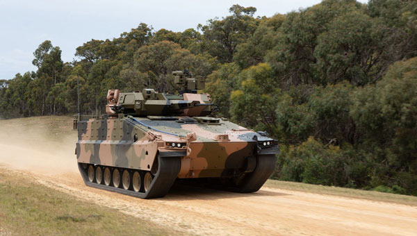
Hanwha Defense Australia’s Armoured Vehicle Centre of Excellence (H-ACE) in Melbourne, Australia, will provide critical facilities supporting the production and sustainment of tracked armored vehicles, including multiple assembly lines, a 1,200 m test track, a deep-water test facility, an obstacle course and a research and development center. Stage 2 of the development will also include Australia’s EMI/EMC (electromagnetic interference/compatibility) chamber and test shooting tunnel alongside an expanded manufacturing capability.
In the neighboring state of New South Wales, Advanced Navigation’s manufacturing facility will be used for the secure production of APNT solutions. Specifically, it enhances the critical output of strategic-grade DFOGs, which possess the heightened sensitivity necessary to detect the Earth’s rotation.
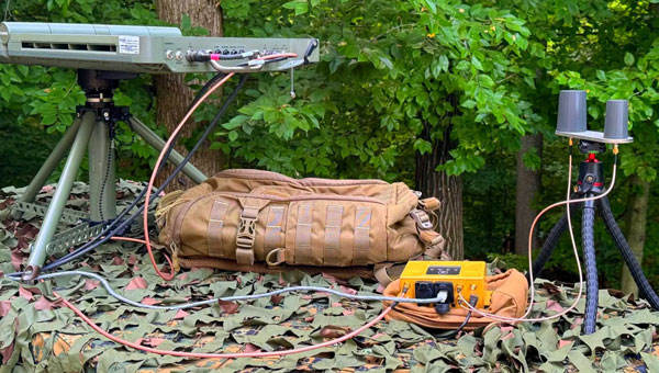
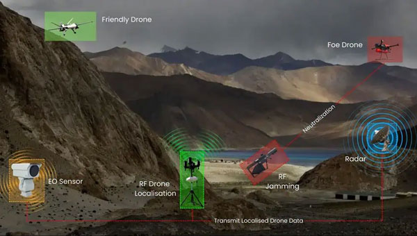
Skylark Labs has released the Aerial Reconnaissance and Elimination System (ARIES), designed to enhance situational awareness and counter emerging threats.
ARIES utilizes artificial intelligence (AI) to detect, classify and respond to threats in real-time. The system’s AI continuously adapts to new threats across multiple domains without requiring manual updates to improve situational awareness and accelerate decision-making for military personnel.
The system can detect and track UAVs beyond visual line of sight (BVLOS). This capability extends the range and effectiveness of counter-unmanned aerial system (C-UAS) operations, providing early warning and enabling rapid response to potential threats.
ARIES seamlessly integrates with existing defense infrastructure, which eliminates the need for frequent manual system updates and seeks to improve overall mission success rates.
The system has been successfully demonstrated to key Department of Defense (DOD) stakeholders, showcasing its potential to enhance counter-UAS operations. During the demonstration, ARIES offered critical, real-time intelligence for swift decision-making in response to UAV incursions.