First UAE government entity to join global geospatial organization
Dubai Municipality has become the first government entity in the United Arab Emirates to join the International GNSS Services (IGS), a global organization specializing in satellite-based geospatial systems, precision surveying, and global reference frameworks.
The IGS supports optimization of GNSS, plate tectonics monitoring, and the calculation of International Terrestrial Reference Frames (ITRFs).
This recognition reflects Dubai Municipality’s continued efforts to strengthen its surveying infrastructure and geospatial capabilities to support urban development, infrastructure planning, and construction. It also underscores the municipality’s commitment to advancing research in geodesy and hydrographic mapping, developing digital navigation maps, and contributing to global knowledge-sharing in the geospatial field.
By joining IGS, Dubai Municipality gains access to the GNSS service and the international reference framework used in scientific, commercial and educational applications. The IGS brings together more than 200 research institutions, universities and agencies from more than 100 countries, offering precise satellite orbit data and enabling high-accuracy positioning and mapping.
“Dubai Municipality’s accession to the International GNSS Services represents a major milestone that reinforces the position of Dubai and the UAE as global hubs for scientific innovation and geospatial excellence,” said Maryam Al Muhairi, CEO of the Buildings Regulation and Permits Agency at Dubai Municipality. “This membership enables collaboration with more than 350 members worldwide, including major scientific organizations and international institutions specializing in navigation, climate studies, Earth dynamics, and advanced surveying applications.”
She added that the membership would contribute to the implementation of Dubai Municipality’s strategic goals by enhancing surveying operations and 3D mapping, integrating research insights into infrastructure and urban planning projects, and promoting a smarter, more sustainable construction sector. It also supports Dubai’s digital twin ecosystem and the emirate’s vision for a globally leading, high-quality urban environment.
Membership will also facilitate collaboration in a range of specialized research fields, including coordinate system referencing, tectonic plate monitoring, Earth rotation studies, navigation systems development, and climate impact modeling.
A roundup of recent products in the GNSS and inertial positioning industry from the January-February 2026 issue of GPS World magazine.
Autonomous
1. Delivery Drones
Volatus deploys medical supplies in Canada
Image: Trimble
Volatus Aerospace has integrated the Trimble PX-1 RTX solution into its commercial delivery drone service to achieve accurate and robust positioning and heading. The Trimble module provides Volatus’ clients with a turnkey solution for highly accurate aerial data acquisition and fully remote drone operations in real-world missions, including beyond visual line of sight (BVLOS). The PX-1 RTX uses Trimble’s CenterPoint RTX corrections along with compact, high-performance GNSS-inertial hardware to deliver real-time, centimeter-level positioning and highly precise inertial-derived true heading measurements. This technology reduces operational risks associated with poor sensor performance or magnetic interference by providing enhanced positioning redundancy.
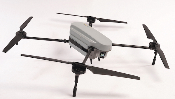
For border protection and long-range surveillance missions
Image: CopterPIX
The ERE95 Mini by CopterPIX operational platform is fully capable of GNSS-denied missions and integrates a long-range, anti-jamming communication system supporting distances of more than 20 km. It has an endurance of 2 hours and can carry up to 5 kg of payload for up to 1 hour. It also has integrated daylight and thermal imaging for advanced surveillance. With a fully foldable frame, the platform collapses into a backpack-sized kit, making it suitable for rapid mobility and field operations. Its modular “puzzle” architecture allows quick adaptation of SDR modules, optical payloads, and navigation solutions, enabling mission-specific configurations. To support rapid field deployment, the ERE95 Mini features a mechanical and electrical quick-connect interface, allowing operators to switch payloads in seconds and maintain continuous operational readiness across all missions.
Integrated into long-endurance unmanned aircraft system
Image: AeroVironment
AeroVironment has integrated its visual navigation system (VNS) kit with the Puma Long Endurance (LE) small unmanned aircraft system, delivering GNSS-denied navigation capability. The VNS kit uses advanced computer vision and onboard processing to deliver precise, GNSS-independent navigation. Using a suite of downward-facing sensors, cameras and onboard computing, the VNS kit performs visual inertial odometry to capture and analyze terrain imagery, estimating true aircraft position in real time. The system fuses continuous visual data from the cameras with motion inputs from onboard inertial sensors to calculate precise position, velocity and orientation — allowing the aircraft to know where it is and where it is going when GNSS is not available. It automatically transitions between GNSS-enabled and GNSS-denied modes with zero pilot input, ensuring uninterrupted mission continuity in contested environments.
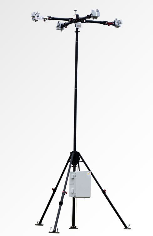
Low power, small footprint setup for close-airspace awareness
Photo: MatrixSpace
The Portable 360 Radar is a rugged, easily transportable radar kit that delivers reliable close-airspace awareness with panoramic coverage for rapid-response counter-drone operations, from safeguarding stadiums and large public gatherings to border security and battlespaces. The MatrixSpace platform unifies threat awareness across multiple networked Portable 360 Radar systems and other sensors, without compromising local operation. By combining AI edge processing with MatrixSpace AiCloud Enterprise software, central command centers get an enhanced common operating picture and deep airspace activity analytics to assure public safety.
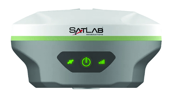
The SatLab SL8 Laser RTK GNSS receiver combines dual cameras, GNSS, an IMU and visible laser technology to make surveying faster and easier. With non-contact measurement, image-assisted targeting, CAD live-view stakeout, and a built-in LoRa radio. It ensures smooth, reliable work even in complex or GNSS-limited environments. The SL8 achieves 2 cm accuracy within 10 meters and enables efficient data collection across bridges, tunnels, riverbanks, and other sites where traditional GNSS methods are restricted. It features image-assisted targeting through SatSurv software, displaying laser points directly on real-time images for quick and precise aiming. Its automotive-grade IMU requires no manual calibration or initialization and enhances measurement accuracy by up to 40% in GNSS-challenged areas. A built-in multi-protocol LoRa transceiver provides stable transmission beyond 15 km and compatibility with multiple RTK brands. The integrated CAD and visual stakeout functions combine live imagery with CAD data, allowing users to visualize target points on site and increase layout efficiency by up to 50%.
A complete precision mapping solution for the utility and critical infrastructure industries worldwide is the goal of a partnership between ProStar Holdings and Tersus GNSS. The partnership will integrate Tersus’s survey-grade GNSS receivers with ProStar’s PointMan Underground Utility Mapping Software, providing an affordable, field-ready solution. The partnership will use ProStar’s LinQD open API integration platform, which is designed to enable seamless interoperability between emerging technologies and legacy systems, creating a robust global ecosystem for geospatial intelligence, uniting equipment manufacturers and service providers under the initiative.
The MVP S1 RTK-SLAM handheld 3D laser scanner uses GNSS through an AI-driven RTK-SLAM workflow, as well as lidar data with imagery from dual 48-megapixel panoramic cameras. The combination provides survey-grade results in both GNSS-denied and open environments. The system achieves centimeter-level accuracy outdoors and maintains performance indoors or underground through SLAM processing. TimeSync 3.0 synchronizes the hardware, aligning sensor data at the microsecond level and supporting consistent datasets and reliable post-processing. A mobile application provides users with real-time feedback, including previews of colorized point clouds while scanning, as well as basic scan reports on site. This feature helps operators verify data completeness and quality before leaving the field, reducing the need for repeat visits. The MVP S1 supports 3D gaussian splatting (3DGS), enabling creation of textured, photorealistic 3D models. This capability is useful for building information modeling, construction progress monitoring, underground surveys, forestry analysis and industrial site documentation.
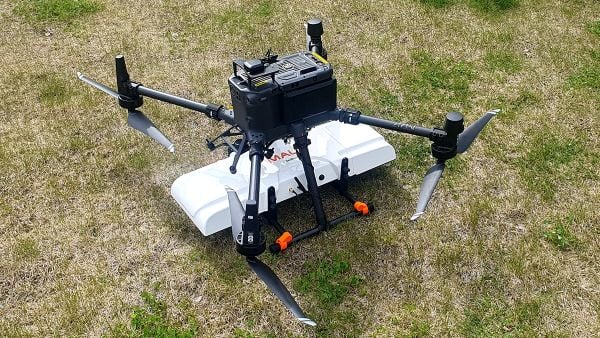
The MALÅ GeoDrone 600 and Zond Aero 600 NG are two new high-resolution ground-penetrating radar (GPR) systems for UAVs. They significantly enhance high-resolution subsurface investigations with drones, supporting applications in engineering surveys, utility mapping, archaeology, environmental studies and geophysical research. They enable surveyors to capture consistent, high-quality subsurface data in areas difficult, slow or unsafe to access with traditional ground instruments. Operating at 600 MHz, the antennas offer a balance between penetration depth and fine near-surface resolution. Typical penetration from the drone is up to 2 meters, depending on surface conditions, while SPH Engineering’s True Terrain Following ensures stable antenna height to maintain data quality and repeatability.
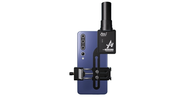
For high-precision surveying, photo surveys and 3D modeling
Image: Aurora Navigation
The Astra1 Mobile Visual RTK is a professional-grade GNSS receiver engineered to redefine high-precision mobile data acquisition. It is built to meet the demand for highly portable, reliable, high-precision tools that simplify complex field operations. At 60 grams, the Astra1 is an ultra-compact solution designed to deliver reliable, centimeter-level positioning and advanced 3D mapping capabilities through seamless integration with a smartphone and the proprietary Anypos App. Accuracy is RTK 8mm+1PPM horizontally, 15mm+1PPM vertically, photo survey <4 cm (2-15 m distance). The Astra1 allows users to capture photos with precise RTK coordinates, enabling the creation of accurate 3D models for detailed construction verification and digital twinning applications.
The AR588MA is a 5G-advanced (5G-A) automotive-grade cellular module that integrates dual-band GNSS supporting both L1 and L5 bands with up to 30 Hz output. Based on MediaTek’s latest-generation MT2739 platform, the AR588MA supports 5G-A communication technology and complies with the 3GPP R18 standard protocol. It features both NB-NTN and NR-NTN satellite communication capabilities and supports dual-SIM dual-active (DSDA) technology, offering improved stability and reliability on cellular connections. It also includes intelligent driving scenario recognition. Designed in compliance with the AEC-Q104 Grade 2 automotive standard, it delivers fast, stable connectivity and reliable security for in-vehicle communication and benefits on-roof applications, such as smart antennas for automotive, with higher-temperature support.
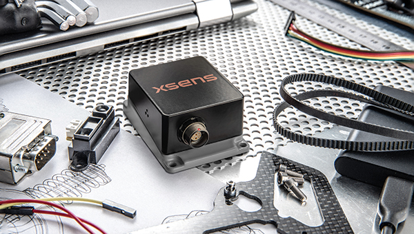
A firmware upgrade to the Xsens Sirius and Xsens Avior IMUs delivers centimeter-level vertical displacement measurements for marine stabilization and control systems. The new Heave feature enables real-time stabilization and wave compensation in a wide range of marine applications. Marine engineers can access comprehensive motion data — roll, pitch, yaw and heave — from a single compact sensor, eliminating the need for external processing or oversized tactical-grade systems while maintaining the precision required for offshore platforms, vessels, docking systems, marine robots, buoys and surveying equipment.
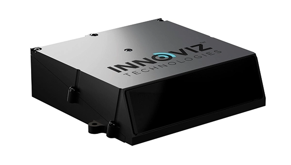
The InnovizThree is fully colored long-range lidar with camera that creates a compact sensor-fusion module designed to reduce OEM integration complexity. The solution combines lidar and RGB sensing in a single compact perception module, purpose-built for behind-the-windshield installations, drones, micro-robotics and humanoids. The consolidation of an RGB camera inside InnovizThree reinforces Innoviz’s commitment to scalable, OEM-friendly sensor-fusion perception solutions designed for series production and long-term deployment, with the potential to enable faster deployment and cost savings. The RGB sensing capabilities are factory-aligned with the lidar, enabling precise and consistent visual-to-lidar geometry across production units. This alignment, combined with hardware-synchronized capture, will enable reliable multi-modal sensor-fusion data correlation while reducing calibration effort during vehicle integration.
High-integrity GNSS integration for autonomous driving
Image: Getty Images / iStock / FlashMovie
Swift Navigation is collaborating with Nvidia to enable a scalable, cost-effective approach to autonomous driving by integrating the Nvidia Drive AGX platform with Swift’s globally referenced, centimeter-accurate GNSS positioning. Swift Navigation offloads absolute localization to the GNSS sensor stack using its Swift Automotive Suite. The suite is a complete, modular software solution for safe, high-integrity precise vehicle localization that combines the centimeter-level Skylark Precise Positioning Service with the Starling positioning engine, software that fuses raw GNSS data and corrections with IMU and wheel odometry to deliver high-integrity, centimeter-accurate positioning (PVT). By using Swift’s high-precision stack for lane-level positioning, the vehicle’s optical sensors focus on obstacle detection and safety, lowering system cost and complexity.
Sinclair’s new SM 5G Family Tier features the SM714 and SM2601 series antennas. The multi-band, multi-port antennas are engineered to deliver superior connectivity, reliability and versatility for GNSS and other mission-critical wireless transportation applications. The SM714 is a 4-in-1 low-profile customizable transit antenna that combines 5G/LTE, Wi-Fi and tri-band GNSS coverage in a single compact form. Supporting 617–5925 MHz, it enables seamless operation across all major 5G and LTE bands. It is suitable for vehicles, fleet systems and connected mobility applications requiring a discreet, high-performance solution. The SM2601D is a 5-in-1 low-profile customizable antenna that features five independent ports: one for PTC (219–223 MHz), one for Wi-Fi (2400–6000 MHz), one for GNSS, and two full-band cellular ports (694–2700 MHz) that support diversity and MIMO operation for multi-radio systems. This dual-cell configuration offers greater throughput, flexibility, and redundancy in complex communication environments.
High-precision depth sensing and real-time velocity measurement
Image: Voyant Photonics
New versions of the Carbon lidar platform add 32-line and 64-line variants for compact, cost-sensitive and compute-limited systems. The new models complement existing 128-line configurations and are optimized for industrial autonomy, robotics, drones and smart infrastructure applications. They offer lower data rates and simplified integration while maintaining core FMCW advantages including velocity measurement, interference immunity and high dynamic range. With line resolutions spanning 32, 64 and 128, original equipment manufacturers and system integrators can tailor performance, bandwidth and compute load to specific use cases, from robotics and automated guided vehicles to drones and embedded edge platforms. The Carbon family’s silicon-photonics architecture integrates beam steering and coherent detection on a single photonic chip. The new variants include high-precision depth sensing and real-time velocity measurement, exceptional ambient light immunity and compact design for industrial and mobile environments.
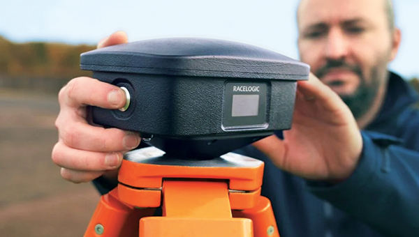
For automotive track and varied environment testing
Image: VBOX
The NTRIP Base Station from VBOX Automotive combines a multi-constellation, multi-frequency GNSS engine with a built-in networked transport of RTCM via internet protocol (NTRIP) server. The equipment transmits real-time kinematic corrections over radio and cellular or Wi-Fi networks, supporting accurate real-time positioning across wider areas in varied environments compared to traditional radio-only systems. The base station launches in three models, with specifications designed to fit users’ needs. All systems combine quad-constellation, dual-frequency GNSS technology with built-in cellular and Wi-Fi connectivity. Compatible with VBOX 4, VBOX 3iS and external GNSS rovers, the new NTRIP Base Station supports both MSM4 and MSM7 RTCM formats, has up to 24 hours of battery life and is rated to IP67 to handle the demands of long outdoor test sessions. Models include Internal GNSS antenna and 2.4 GHz radio (quick to deploy for short-range applications, for temporary or mobile testing); Internal GNSS antenna, no radio (compact and simple, suitable for NTRIP or semi-permanent installations with external high-power radio masts); and External GNSS antenna, no radio (optimized for permanent installations with tripod-mounted antennas for maximum satellite visibility, supporting NTRIP or external radio).
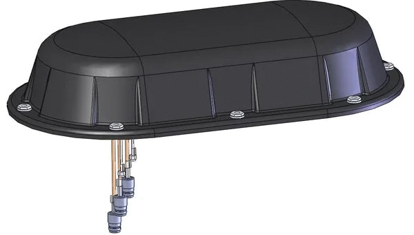
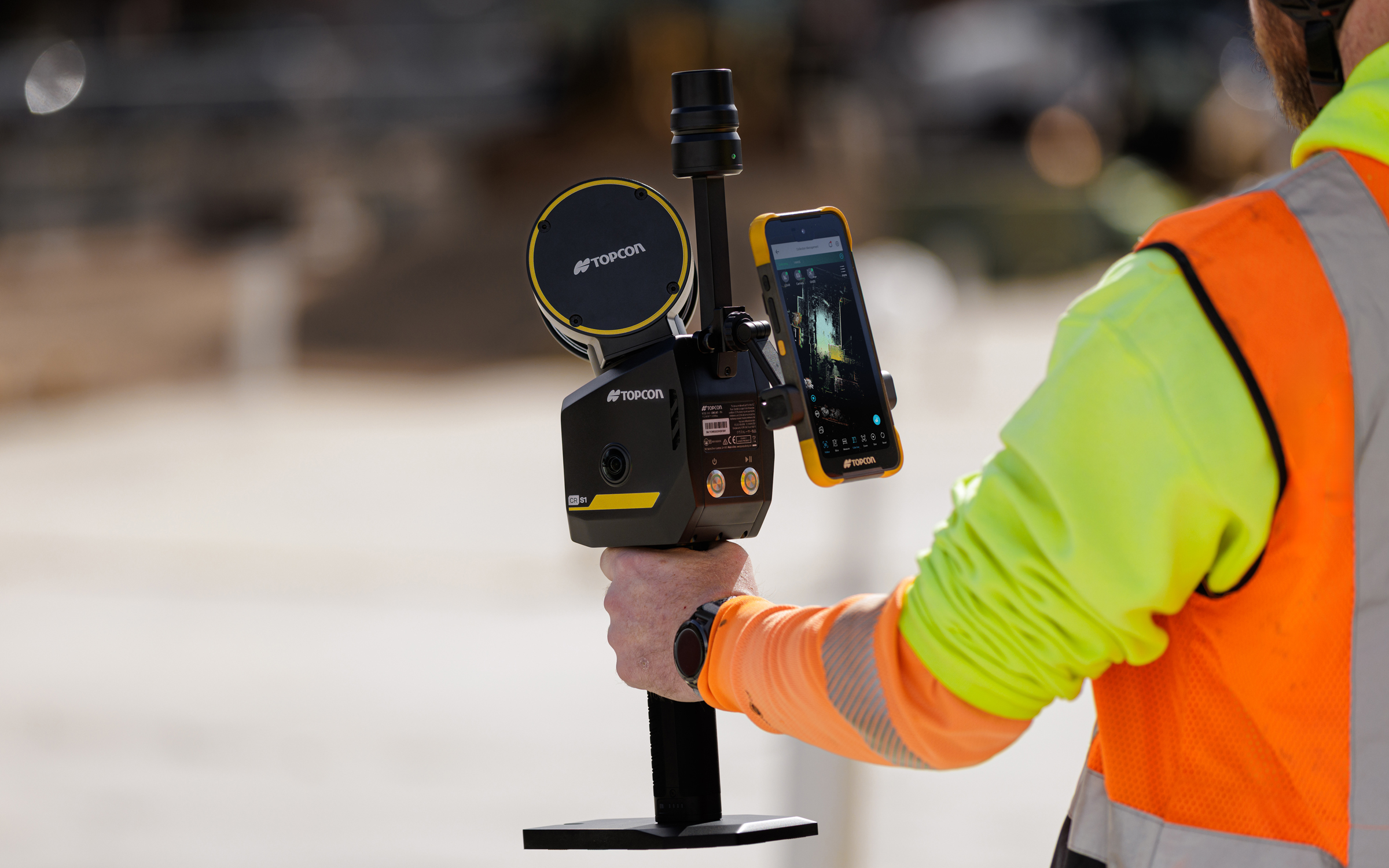
Topcon Positioning Systems has introduced the CR-S1, a handheld scanning system that combines ldar, panoramic cameras, visual SLAM cameras, and a GNSS antenna in a single device.
The CR-S1 expands the company’s Capture Reality portfolio as a higher‑performance option alongside the CR‑S2. It offers increased point‑cloud density, extended scanning range, and upgraded panoramic imaging.
The CR-S1 uses Topcon’s Collage mass-data software ecosystem central to a connected workflow.
For added positioning accuracy, the CR‑S1 can be connected to the Topnet Live RTK GNSS corrections service.
The system is primarily intended for surveying and construction. It is also well-suited for applications such as land surveying, tunnel surveying and modeling, forestry analysis, mining operations, utility mapping, and powerline inspection.
“Customers are looking for flexibility and efficient workflows, and our scanning portfolio and software are designed to support these needs through simplified processes, open integrations and mixed‑fleet compatibility,” said Ron Oberlander, head of the Topcon Geomatics Platform. “With Collage serving as the central data hub supporting inputs from multiple sensors, users can obtain accurate, detailed information for decision‑making.”
Software support includes MAGNET Flow for Android and iOS devices, MAGNET Bridge for SLAM data desktop processing, and Collage Web.
Topcon Collage Web is a cloud‑based platform for fast visualization, exploration, and sharing of 3D point‑cloud data directly in a web browser. It enables users to easily view and inspect datasets while supporting efficient collaboration across projects. Through the Collage Cloud Connector desktop application, projects are seamlessly synchronized with Collage Web, allowing smooth integration with Autodesk and ClearEdge3D software. This workflow supports mixed fleets and diverse industry systems, ensuring efficient data exchange and consistent project access across desktop and cloud environments.
Mounting options include backpack and front‑pack configurations for hands-free, load-bearing scanning while walking, as well as rover–pole operation. An adapter for mounting the CR-S1 on a vehicle for mobile mapping is also available.
The CR‑S1 is being showcased at Geo Week 2026, Feb. 16–18, in Denver, Colorado. It will be available through the Topcon dealer network with training and support.
GeoCue has announced the upcoming release of the TrueView GO NEO, a handheld SLAM lidar system that expands the company’s TrueView handheld lidar product lineup.
Unveiled at Geo Week 2026 in Denver, The TrueView GO NEO adds a smaller, lighter, more portable option designed to make handheld mapping easier, more flexible, and more affordable, especially for indoor capture. It pairs with a smartphone, keeping the workflow streamlined and the total cost of ownership low.
Since introducing the original TrueView GO 116S and TrueView GO 132S handheld systems, GeoCue has seen rapid adoption of handheld mapping workflows across surveying, construction, public safety, facility documentation, and more. The new TrueView GO NEO extends that momentum with a rugged design and high performance for teams who need dense data and dependable SLAM in corridors, stairwells, mechanical rooms, and other GNSS-challenged environments.
Indoor mapping
The TrueView GO NEO was designed as a complete, end-to-end workflow, helping teams move quickly from data acquisition to usable results in complex indoor environments. At its core is a new high-rate scanning engine capable of capturing up to 1.15 million points per second, delivering dense detail while improving field efficiency. An ultra-wide field of view (360° × 189°) increases coverage overhead and helps reduce missed areas, so users can capture complete scenes faster without “painting” every surface.
The NEO also introduces Deep INS + SLAM Fusion, pairing SLAM mapping with a high-grade inertial navigation system to improve stability in feature-poor environments where typical consumer-grade navigation can struggle. The result is more reliable trajectories and improved point cloud integrity in challenging scenarios, such as long corridors and multi-floor stairwells, where drift and misalignment can degrade results.
To enhance interpretation and deliverables, the TrueView GO NEO includes HD colorization and advanced image capture to support panoramic imagery and detailed colorization even in low light. Users can also leverage these images to create visual outputs such as mesh models and high-fidelity reality renderings for downstream documentation and visualization workflows.
Paired with LP360 Land
TrueView GO NEO is paired with LP360 Land, GeoCue’s software for handheld lidar processing, QA/QC, visualization and deliverable creation. LP360 Land enables users to generate detailed point clouds from raw data, validate coverage and quality, and produce outputs aligned to project workflows without unnecessary complexity.
The NEO is also designed to keep workflows streamlined, pairing conveniently with a phone and supporting device-to-cloud options through the LP360 Cloud platform. Users can upload captured data over Wi-Fi or hotspot for automated post-processing or use an LTE-based workflow to upload data.
Highlights
Smaller, lighter handheld SLAM lidar designed to “complete the range” of the TrueView GO lineup
High-speed point capture for fast, dense indoor reality capture
Ultra-wide field-of-view scanning to improve coverage and reduce blind zones
Precision IMU for low-drift SLAM, supporting reliable results over longer sessions even in typical SLAM challenging conditions
Integrated HD imaging for spherical capture and high quality colorization
Built-in GNSS for georeferencing workflows when GNSS is available (RTK/PPK capable)
“Smart Handle” integrating the battery with hot-swap battery capability for continuous scanning
Autonomous mapping company Emesent has launched the Emesent GX1, an integrated simultaneous localization and mapping (SLAM) and real-time kinematic (RTK) scanner. The company is exhibiting the GX1 at Geo Week 2026 (booth #911).
The product achieves 5-10mm global accuracy to deliver high precision for topographic surveying and building and infrastructure construction. It can reduce the time required to survey a site by up to 95% with a single day of scanning replacing weeks of work, Emensent stated in a press release.
The GX1 is an integrated, all-in-one system where lidar, RTK, cameras and software work together seamlessly from capture to validated deliverable. Its SLAM technology was proven in the world’s most challenging environments to everyday surveying applications, but it also eliminates the longstanding trade-off faced by survey firms and the architecture, engineering and construction (AEC) industry between mobile scanning speed and dependable survey-grade accuracy.
Suited for use cases across topographic and road survey, scan to building information models (BIM), construction progress tracking and more, the GX1 is simple enough for junior surveyors to train on and deploy in a matter of days yet powerful enough to meet the needs of experts in the field.
Accuracy. GX1 is the only SLAM-based mobile scanner system delivering 5-10mm global accuracy combined with rapid scanning capabilities. Incorporating client-first design, integrated RTK and Emesent’s proprietary SLAM algorithm, GX1 offers repeatable results survey firms can rely on.
Proven SLAM algorithm: Emesent’s SLAM technology, which powers its award-winning Emesent Hovermap product, was developed and validated in some of the most extreme real-world environments, includidng GPS-denied underground locations. It delivers repeatable accuracy both indoors and out.
Versatile deployment: GX1 has four purpose-built deployment modes: backpack, survey pole, vehicle mount, and supported handheld. Flexible georeferencing minimizes the risk of having to return to a site for redo – surveyors can capture with RTK in the field or with ground control points and checkpoints in post-processing.
The GX1 is being launched at a pivotal moment for survey firms and the AEC industry, which are grappling with a shortage of experienced surveyors, Emensent stated. At the same time, firms face mounting pressure from clients demanding faster, cheaper and better results without quality compromise, alongside the diminishing competitive advantage of adopting basic mobile scanning technology.
“With the introduction of the GX1, we’ve answered the call we’ve heard echoing throughout the surveying industry to end the tug-of-war between fast and accurate,” said Stefan Hrabar, chief strategy officer and co-founder of Emesent. “By putting the power of SLAM into the hands of the everyday surveyor, the GX1 raises the bar for mobile scanning accuracy and keeps critical projects on track.”
Technical Features
Independently validated 5-10mm global accuracy
Integrated RTK georeferencing with real-time quality monitoring
4 x 20MP cameras for 360° panoramic imagery
Emesent SLAM algorithm
Four deployment modes: backpack, survey pole, vehicle mount, handheld
Integrated batteries for cable-free management
Rapid accuracy validation reports in Aura processing software.
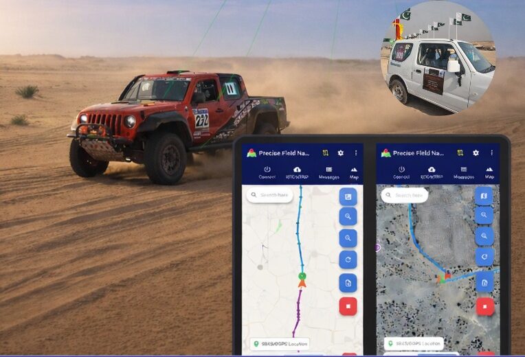
Pakistan’s national space agency SUPARCO (Space and Upper Atmosphere Research Commission) has achieved a major milestone in navigation technology with the successful launch of its Pak-SBAS satellite-based augmentation system (SBAS) device and service.
The Pak-SBAS navigation service was rigorously tested in the extreme desert conditions of Cholistan during Cholistan Desert Rally 2026. The Cholistan desert experinces high speeds, unpredictable routes, and the absence of visual landmarks that demand exceptional positioning accuracy and signal reliability for autos and motorcycles.
Throughout the rally, Pak-SBAS demonstrated remarkable performance by delivering highly precise location data, stable signal continuity, and integrated route tracking.
By applying SBAS corrections, the system significantly reduced positioning errors compared to conventional GNSS technologies, offering rally drivers and navigation teams a new level of confidence essential for competitive desert racing.
According to a SUPARCO spokesperson, the Pak-SBAS technology holds vast potential beyond motorsports. It is expected to enhance disaster response operations through accurate tracking of rescue teams and affected areas, improve transport efficiency via real-time vehicle positioning, and strengthen aviation safety with more reliable navigation support.
The system also will benefit the surveying and mapping sectors by minimizing positional inaccuracies and reducing project costs.
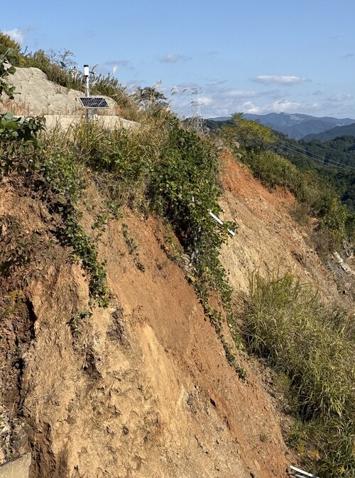
Divirod and Oki Electric Industry (OKI) have completed a project to monitor landslide risk and slope stability across vulnerable areas in the Fukuoka Prefecture of Japan. The project deployed Divirod’s next-generation ground deformation and anomaly-detection technology to provide continuous, high-resolution monitoring of mountainous terrain prone to extreme rainfall and seismic activity.
The initiative supports Japan’s broader effort to enhance early-warning capabilities and strengthen climate resilience following recent years of severe rainfall disasters and complex terrain-related hazards.
Monitoring with GNSS-R technology
For the project, Divirod designed a system comprised of GNSS-Reflectometry (GNSS-R) sensors and intelligent algorithms and deployed it across three areas of interest collecting continuous, all-weather measurements throughout the monitoring period. Divirod’s proprietary algorithms examined daily GNSS-R measurements to detect even subtle changes in the ground surface.
Divirod’s system successfully classified the observed terrain changes into three key physical categories:
Slope failure events,
Creep/slow-moving landslides, and
Temporary terrain changes (often linked to rainfall or ground moisture variations).
Hundreds of terrain changes were detected across the monitored regions and correlated with rainfall measurements and earthquake events. The results enabled detailed risk mapping and precise identification of active zones.
The technology proved highly sensitive in differentiating short-lived disturbances from long-term geomorphological changes — an essential capability for early intervention and warnings.
Documented landslide at Hakikoga
A significant project highlight was successful detection of a real landslide event in August. While comparison images taken on Aug. 10 and 11 revealed visible changes in the slope during daylight hours, Divirod’s terrain change maps show that the slope movement itself occurred overnight, a time when on-site cameras were unable to observe the event due to darkness.
Despite the lack of visual evidence, Divirod’s GNSS-R sensors registered a distinct spike in ground-movement, accurately detecting the terrain shift and providing clear evidence of a nocturnal landslide that could have otherwise gone unnoticed.
Strengthening the disaster-preparedness ecosystem
Divirod’s collaboration with OKI represents a significant advancement in real-time terrain intelligence for Japan, a region characterized by frequent typhoons, intense rainfall and high seismicity. The successful deployment in the Fukuoka Prefecture presents new opportunities for:
scalable early-warning systems,
automated landslide risk modeling,
and the integration of GNSS-R sensing with existing monitoring infrastructure.
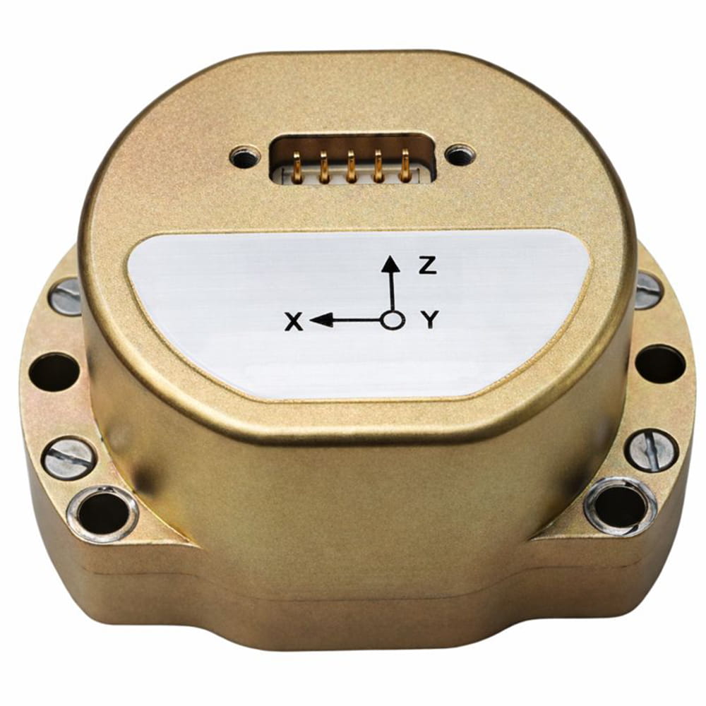
Micro-Magic has released the U4930 series, a reliable and cost-effective six-axis MEMS inertial measurement module that can be widely used in navigation, control and measurement fields for vehicles, ships and drones.
Typical applications include vehicle/ship attitude measurement, UAV attitude reference and trajectory control, mobile mapping, track inspection, underwater high-precision navigation, and Satcom-on-the-Move.
The U4930 series integrates high-performance MEMS gyroscopes and MEMS accelerometers within an independent structure. The three-axis MEMS gyroscopes sense the angular motion of the carrier, and the three-axis MEMS accelerometers sense the linear acceleration of the carrier.
The system internally performs compensation for zero bias, scale factor, non-orthogonal error, and acceleration-related terms across all temperature parameters, maintaining high measurement accuracy over a long period of time.
The module supports custom communication protocols and provides synchronization for GPS/GNSS time data and pulse per second (PPS) signals.
The U4930A series inertial measurement module can be configured with various hardware and software to meet user needs.
Australia-based Aptella is offering free access to its AllDayRTK high-accuracy positioning service for volunteers and organizations involved in bushfire and flood recovery efforts.
Reliable positioning aids in coordinating recovery operations, assessing damage and restoring essential infrastructure. However, extreme weather events often disrupt permanent GNSS base stations due to power outages and loss of internet connectivity.
To address this challenge, AllDayRTK has developed a Synthetic Base Station system, enabling high-accuracy positioning even when permanent bases are offline. This technology creates a virtual reference station network that ensures continuity of service in disaster-affected regions, supporting emergency response teams and volunteers where traditional infrastructure cannot.
Key Benefits:
Free access for registered volunteers and recovery organizations.
High-accuracy GNSS positioning for mapping, surveying and logistics.
Synthetic Base Station technology ensures service continuity without reliance on damaged or offline permanent bases.
“Aptella is always willing to do what we can to support volunteer services with high-accuracy positioning that assist with recovery after natural disasters and extreme weather events,” said Greg Macklin, CEO at Aptella. “Our commitment is to ensure that those on the front lines have the tools they need to rebuild communities quickly and safely.”
The FGCS meeting took place on Wednesday, Jan. 21, 2026. This session was highly informative and played a key role in aligning federal agency engagement strategies and self-assessments in preparation for the final adoption of the modernized NSRS and its associated new datums.
Advancing the use of authoritative geodetic control
Facilitating the modernization of the NSRS across agencies
Recommending the official adoption of the modernized NSRS by the FGDC as the foundational basis for geodetic control throughout the United States.
The agenda for the Jan. 21 meeting is detailed in the section titled “Federal Geodetic Control Subcommittee Meeting.” This gathering supported broader efforts to raise awareness, ensure coordination and prepare agencies for the upcoming transition to the modernized NSRS, with formal approval and release anticipated later in 2027.
Federal Geodetic Control Subcommittee Meeting
January 21, 2026
Agenda:
MC: Christine Gallagher
Time
Topic
Presenter
1:00 – 1:15 pm
Welcome and Introductions
Daniel Roman
1:15 – 1:20 pm
National Geodetic Survey (NGS) Update
Marian Westley
1:20 – 1:30 pm
Geodetic Control Theme Update and its Modernization Timelines
Daniel Roman
1:30 – 2:00 pm
NGS Modernization Engagement Plan and Progress
Dana J Caccamise II / Christine Gallagher
2:00 – 2:15 pm
Bureau of Ocean Energy Management / Kearns & West
Andy Archer / Kyle Vint
2:15 – 2:30 pm
US Census National Spatial Reference System (NSRS) Modernization Preparation
Vince Ossier / Josh Coutts
2:30 – 2:40 pm
Break
2:40 – 2:55 pm
US Department of Transportation NSRS Modernization Preparation
Amy Nelson / Derald Dudley
2:55 – 3:10 pm
American Society for Photogrammetry and Remote Sensing & National Society of Professional Surveyors Working Groups
Chris Parrish / Linda Foster
3:10- 3:50 pm
Discussion: Q&A from Agency presentations. What hurdles to implementation do you see or anticipate? Share your insights from internal working groups
Group Discussion Moderator: Dana J Caccamise II and Daniel Roman
3:50 – 4:00 pm
Closing Remarks
Daniel Roman
Adjourn to Silver Branch
The meeting lasted three hours and covered a lot of material. Below are highlights; contact FGCS for the full meeting recording.
Christine Gallagher, NGS, opened the FGCS session and introduced Dan Roman, NOAA’s National Geodetic Survey senior advisor for geodesy.
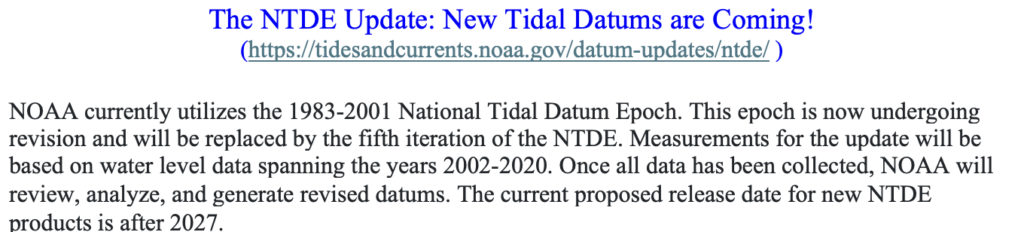
Westley’s remarks were brief but important. She noted CO-OPS manages tide gauges and is updating several datums in partnership with NGS, including the Great Lakes International Great Lakes datum. She said the United States and Canada, along with NOS and other federal agencies such as the Corps of Engineers, are heavily involved in Great Lakes management. She also reported that CO-OPS is updating the National Tidal Datum Epoch (current NTDE: 1983-2001) and is working closely with NGS to tie the updated NTDE to the new NSRS. See the image titled “The NTDE Update: New Tidal Datums are Coming!“
During Roman’s comments, he highlighted the agencies and professional societies participating in the meeting presentations and provided an update on the latest rollout schedule for the modernized NSRS.
He emphasized that this Jan. 21, FGCS meeting marks the start of a broader coordination process. The primary purpose of this high-level session was to facilitate the sharing of experiences, strategies, and best practices among federal agencies as they prepare for NGS’s NSRS modernization and the transition to the new reference frames and datums.
Roman noted that future FGCS meetings will shift to a more technical and detailed focus. These subsequent sessions will allow agencies to present their self-assessment results, outline implementation strategies, and discuss progress toward adopting the modernized NSRS.
Key objectives across these meetings include:
Collecting questions and feedback from participants,
Understanding user needs and required accuracy levels,
Identifying anticipated challenges during the transition,
Exploring opportunities for federal agencies to collaborate and support one another throughout the implementation process.
This series of FGCS engagements aims to ensure coordinated, informed, and effective preparation across the federal government ahead of the final adoption and full rollout of the modernized NSRS.
Here are a few key points based on Dan’s remarks:
Today’s presentations provide a broad overview of geospatial data modernization to inform departments about actions they may need to take and to start a dialogue about what each department is doing.
NGS encourages agencies to form working groups; those groups must define their own requirements and create migration plans, including assessing existing data, required accuracies, and the tools needed based on product accuracy statements. [Note: My October 2025 GPS World newsletter highlighted organizations that are forming 2022 Reference Working Groups.] NGS will designate points of contact to facilitate discussions and planning.
FGCS provides guidance on using geodetic data with various tools, models, and SOPs. User needs vary by accuracy: e.g., a 3-meter horizontal allowance (aids to navigation) is straightforward, while 3-centimeter requirements (e.g., FEMA Elevation Certificate) need more precise methods.
Several beta products released in July 2025 are being finalized, enabling the private sector to integrate them into services. NGS is currently developing models and software to transform coordinates from the old datum to the new one. These models are expected around March, and in June/July NGS anticipates releasing an updated Beta NCAT tool to transform coordinates to the new datum. This tool will help users understand differences in local datums.
Final steps include FGCS recommendations for FGDC to adopt the new NSRS and to publish a Federal Register notice on the adoption of the modernized NSRS, anticipated to be completed in early 2027.
After Dan Roman’s comments, Dana J Caccamise II gave a presentation describing NGS Modernization Engagement Plan and Progress. Dana should get an award for material he has prepared and for his work to assist agencies and professional organizations in preparing for the new NSRS. In my October 2025 GPS World Survey Scenenewsletter, I highlighted the work of Dana J. Caccamise II, NGS regional geodetic advisor. Dana has developed vital guidance materials shared with federal agencies — such as the Federal Geographic Data Committee (FGDC) and professional organizations including the National Society of Surveyors (NSPS), American Society of Photogrammetry and Remote Sensing (ASPRS), and American Association for Geodetic Surveying (AAGS).
Here are a few key points based on Dana’s presentation titled “Visualizing Impact: Preparing for NSRS Modernization Through Geospatial Readiness and Collaboration.”
Caccamise said that what started as a focused task quickly grew into a broader strategic effort. He shared insights to encourage thinking about NSRS modernization not merely as a technical update but as a strategic business decision that will shape how agencies create, manage, and share basic data across programs, systems, and partnerships.
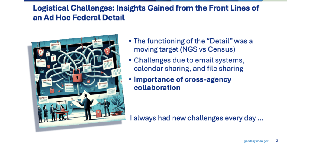
Caccamise briefly provided details to the U.S. Census. Before diving into modernization, he offered a personal glimpse of what it’s like to do a federal detail across agencies, noting he was fortunate to do a detail with the Census not long ago.
Image: FGCS Jan. 21, 2026, Public Meeting
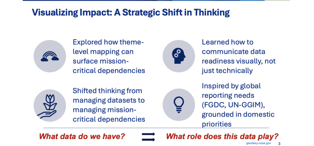
Drawing on his experience, Caccamise emphasized the importance of cross-agency readiness and of building resilient trust and communication structures. While on detail at the Census, he was regularly surprised by new challenges, which made the work engaging; he strongly recommended that others take a detail at another agency if they have the opportunity. A key takeaway was the value of visualizing impact: beyond cataloging geospatial datasets, users must identify which support critical decisions, which are shared across agencies, and which risk becoming outdated if you don’t adapt. Mapping themes and workflows revealed real dependencies and, more importantly, vulnerabilities. That detail shifted his focus from “what data do we have” to “what roles does this data play.”
Image: FGCS Jan. 21, 2026, Public Meeting
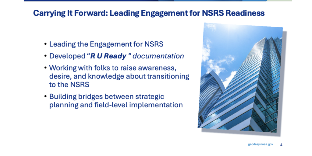
Efforts around NSRS modernization include a key product developed by Caccamise: the Ready Package. Designed to help agencies assess their readiness for NSRS modernization, the package includes communication tools, technical checklists, and talking points to support agency staff.
Image: FGCS Jan. 21, 2026, Public Meeting
He mentioned that from field-level GIS technicians to senior policy leads, everyone needs to understand what’s changing and why it matters. A key part of engagement is meeting people where they are. Dana has worked with agency partners to raise awareness, build interest, and strengthen understanding — not just of technical changes but of the organizational shifts needed for a smooth transition.
For agencies whose statistical workflows depend on spatially referenced data, that means ensuring location-based datasets remain accurate, comparable over time, and interoperable across programs when the reference system changes. Ultimately, this is about more than new coordinates: it’s about linking strategic planning to operational implementation, from data collection and integration to interagency coordination and informed decision-making.
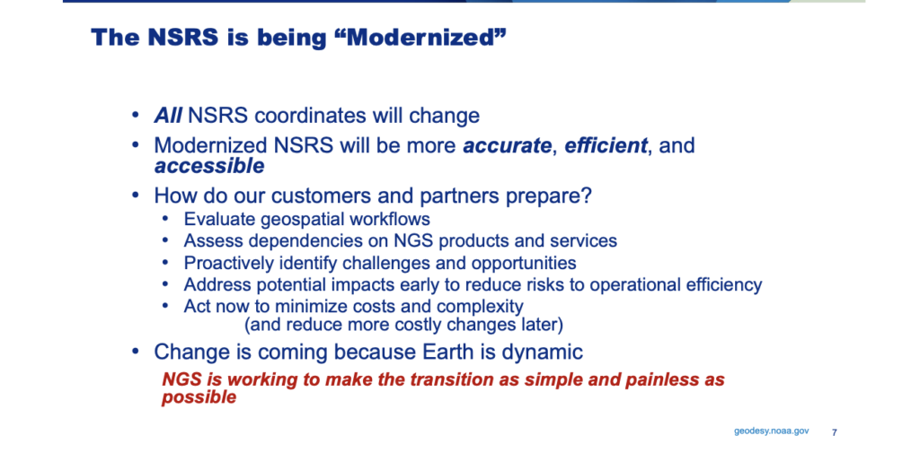
He mentioned that the big question he’s hearing from many organizations is: how should customers and partners prepare for modernization? He provided the following advice. Start by evaluating your geospatial workflows to understand how the transition will affect data management, operations, and decision-making. Assess dependencies on NGS products and services to ensure continued access and interoperability and proactively identify challenges and opportunities – he mentioned that NGS can’t do this for you because each agency’s situation is unique. Address potential impacts early to reduce operational risk by finding weak points before they cause surprises. Act now: preparing early will minimize future cost and complexity.
Image: FGCS Jan. 21, 2026, Public Meeting
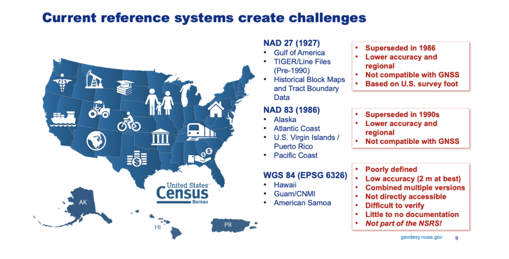
For example, working with the Census under the current national spatial reference system highlights the geographic scope of some operational areas, which span multiple tectonic plates as modeled in the modernized NSRS. Even small regional differences can affect how location-based data are collected, integrated, and compared — especially for programs that need consistent, long-term geospatial baselines. Today, federal agencies commonly use three reference systems — NAD27, NAD83, and WGS84, which complicates geospatial data management.
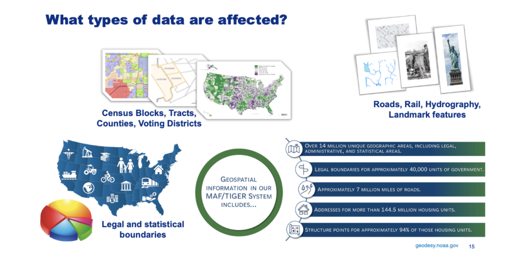
The Census is a major user and producer of geospatial data, relying on GIS to support operations. This includes the MAF/TIGER geographic database, which contains roads, rail lines, hydrography, landmark features, and legal and statistical boundaries.
Along with many other critical datasets, the Census’s collaborative spatial and statistical research is more effective and interoperable when grounded in a common reference system, such as the National Spatial Reference System.
Image: FGCS Jan. 21, 2026, Public Meeting
Because these datasets are inherently geospatial, many, especially those requiring high positional accuracy or relying on external references such as airborne or satellite data, will be affected by NSRS modernization. The update will enable more consistent data stewardship and support integrated spatial analytics, helping align with individual agency spatial data strategies. Bureau-level geospatial work becomes more effective and future-ready when supported by a modern, shared spatial reference system like the NSRS.
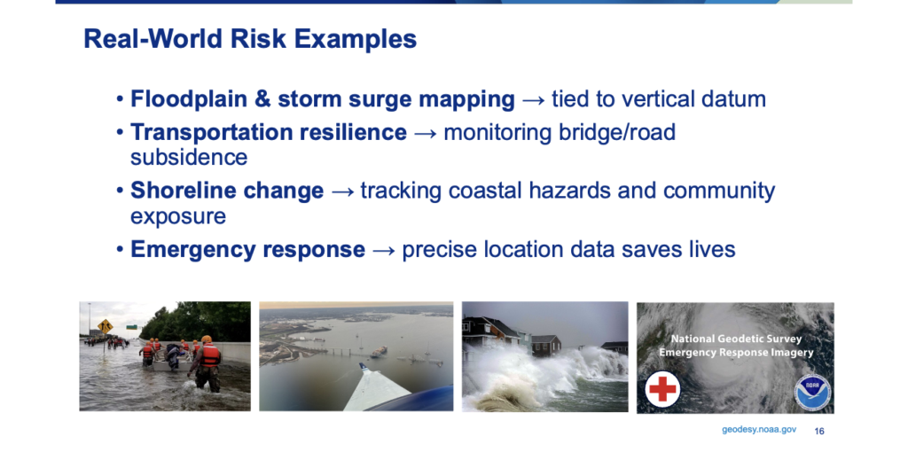
One of the biggest risks is cultural, not technical. If the NSRS is treated as just another dataset, rather than an enabling framework, the foundation for other systems weakens. When the NSRS is recognized as the framework, everything built on it has a solid base. You can’t manage risk if you can’t measure it—and the NSRS is how we measure. Here are a few practical examples.
Floodplain mapping and storm surge models depend on accurate vertical data. Errors of even a foot can leave neighborhoods unprotected or cause unnecessary regulation.
In transportation, subsidence is a hidden risk: roads and bridges may seem fine until precise geometric monitoring reveals sinking.
Shoreline change is a growing challenge; coastal communities need accurate shoreline monitoring for planning and insurance.
In public safety, emergency response relies on precise locations — from 911 calls to field deployments. Seconds and meters matter when lives are on the line.
Image: FGCS Jan. 21, 2026, Public Meeting
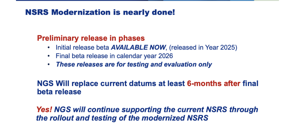
As Roman mentioned, Caccamise also stated that the modernized NSRS is being released in phases. Initial beta releases are available now for testing and evaluation—not final production. NGS plans to release the remaining components in beta during this calendar year. The modernized NSRS will replace the current datums at least six months after the final preliminary component is released, giving partners time to review the beta and provide feedback. Near the end of this period, FGCS will convene to discuss and socialize the modernization details and the planned datum replacement.
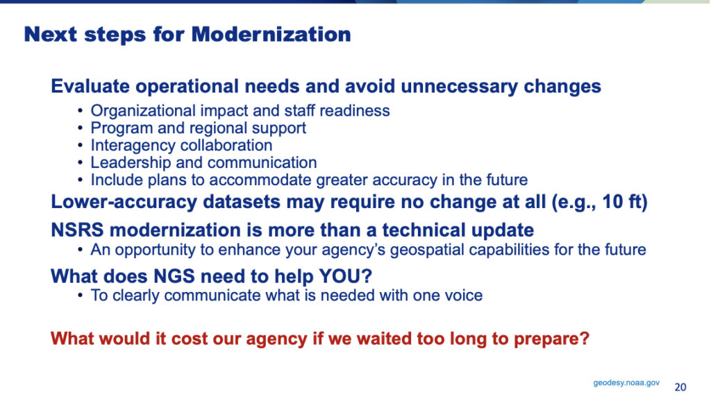
Next steps for your agency’s modernization:
Evaluate operational needs and identify changes that aren’t necessary.
Assess organizational impacts and staff readiness—are teams prepared for modernization?
Determine how existing programs and regional support will be affected.
Collaborate with partner agencies to align shared datasets, reduce redundancy, and maximize efficiency.
Prioritize leadership and communication to ensure the organization understands the changes.
Plan for future improvements in spatial accuracy, even if you don’t need them immediately.
Image: FGCS Jan. 21, 2026, Public Meeting
As noted by Dan Roman, Dana Caccamise also highlighted that many lower-accuracy datasets may not require coordinate changes beyond updating their metadata—typically those with spatial accuracy on the order of 10 ft or worse. However, he also noted an important caveat: many operational workflows don’t actively read or enforce metadata. In those cases, the risk is not the dataset itself but the accuracy context that becomes embedded as data moves through systems.
An early, critical step is therefore to identify not only which datasets are likely unaffected but also how those datasets are consumed, transformed, and reused. That approach prevents unnecessary work and avoids unintended downstream impacts. Remember: NSRS modernization is more than a technical update, it’s an opportunity to strengthen your agency’s future geospatial capabilities.
Now, I know this newsletter is long, but I would like to highlight one more presentation that I believe provides a model for other agencies to follow. That is, the presentation of the Department of Interior’s Bureau of Ocean Energy Management (BOEM) activities presented by Kyle Vint (Vice President, Kearns & West) – “From Proactive Engagement to Lasting Impact: BOEM’s Path to Datum Readiness.”
Image: FGCS Jan. 21, 2026, Public Meeting
Kearns & West is a communications and engagement specialization firm. The materials that they develop to support internal communications and outreach within an organization are available for other organizations. They provided a QR code for others to access their resources.
Vint outlined BOEM’s operating context and described how the agency is proactively addressing NSRS modernization, including several strategies.
Image: FGCS Jan. 21, 2026, Meeting
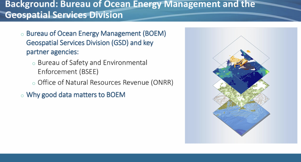
BOEM’s challenges are partly historical: until about 2010, it was part of a parent agency that has since split into three separate agencies. That fragmentation means BOEM must coordinate data and change management not only internally but across three agencies that share data centers and geospatial datasets. BOEM relies on authoritative geospatial data to manage offshore energy and mineral activities on the Outer Continental Shelf; BOEM’s Geospatial Services Division supports this by maintaining leases and boundaries that underpin program decision-making. Because the ocean serves many purposes, BOEM relies on multiple layers of information from different agencies to support those decisions.
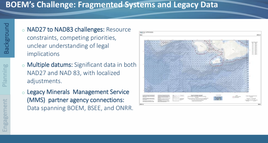
BOEM’s path to modernization is further complicated by internal organizational factors. The agency struggled with the NAD27-to-NAD83 transition due to resource constraints and misunderstandings — some staff believed modernization would alter legal lease blocks, which they expected to be immutable — so the transition was not fully implemented.
Image: FGCS January 21, 2026, Meeting
BOEM holds large datasets in both NAD27 and NAD83, fragmenting its workflow. Maintaining and converting between multiple reference systems is labor-intensive and introduces inconsistencies.
BOEM must dedicate substantial staff time to managing data in multiple reference systems. BOEM’s Geospatial Services Division recognized early that continuing workarounds would increase risk over time, so they began proactive modernization planning.
The Geospatial Services Division saw this as more than a technical issue — it’s also a people, communication, and resourcing challenge. BOEM shifted from fragmented efforts to a proactive, multi‑year planning approach emphasizing governance, leadership buy‑in, and clear communication. The Geospatial Services Division established a milestone‑based approach for consistent messaging and coordination across stakeholders and offers internal expertise to support programs and regions as they assess costs and technical complexity.
Their strategy seeks common ground to pool resources for shared problems and to use the Geospatial Services Division as an internal augmentation so individual offices aren’t forced to opt out. This reduces cost uncertainty and enables realistic planning for timelines and required participants.
Image: FGCS January 21, 2026, Public Meeting
As part of the process, user personas were created to identify who would struggle with each step and who would benefit from early, sustained engagement. For each group, they defined the value of participating and explained why they were invited.
BOEM leaderships were treated like investors—they ensured they brought geospatial experts to meetings so questions could be answered, and so leadership had actionable budget information for long‑term planning. At the program and regional level, data experts who know existing datasets, reference systems, dependent applications, and potential workflow challenges were part of the process.
They also documented internal roles so others can model the approach. The Geospatial Services Division coordinates the effort across the organization. Program and regional experts provide domain knowledge. Kearns & West (technical and communications contractors) supported messaging, prepared materials, and ran meetings so BOEM staff could focus on the conversation. Clear roles and sustained engagement have been critical in this multi‑year planning effort.
Image: FGCS January 21, 2026, Public Meeting
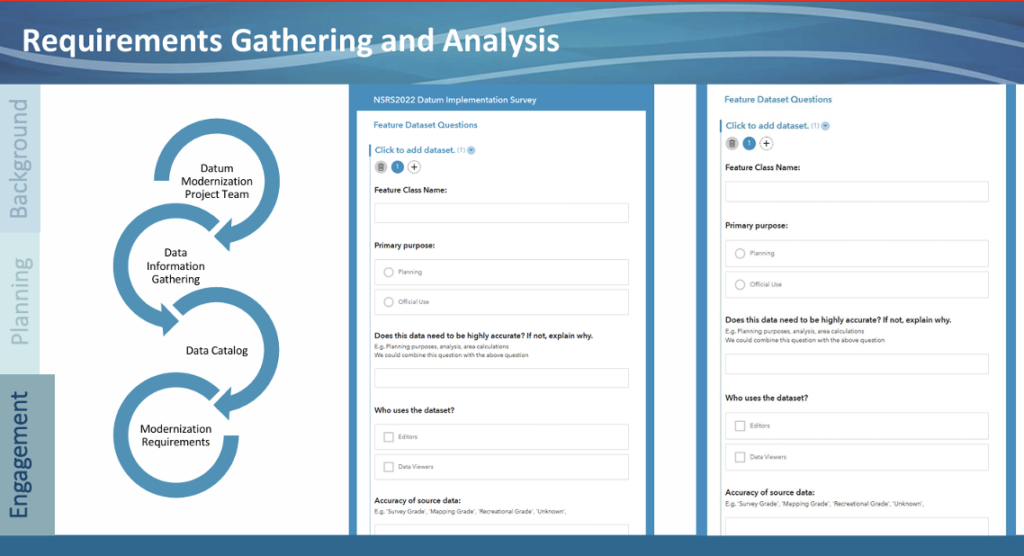
The team developed a Survey and sent it to each program and region to gather resource requirements. The survey asked what data they have and its characteristics, which applications or workflows depend on that data and could be affected by modernization, and what technical resources they expect will be needed to support budgeting.
Image: FGCS January 21, 2026, Meeting
As part of the process, they are building internal champions to advocate for the effort, simplifying complex issues so staff can brief leadership, and convening agencies, partners, and industry to co-create solutions.
Tactical air-lifters such as the Airbus A400M, Lockheed C-130 and Boeing C-17 require precise runway roughness assessments to operate safely on unpaved surfaces. An autonomous rover system developed at the Royal Military Academy of Belgium uses RTK/PPK GNSS positioning and sensor fusion to deliver centimeter-level height measurements, drastically reducing survey time. The system provides a practical solution for rapid runway certification across military operations and humanitarian response missions.
Unpaved runway assessment
The Airbus A400M Atlas, the Lockheed C-130 Hercules and the Boeing C-17 Globemaster III routinely operate from unpaved runways in harsh environments far from established infrastructure. Before these aircraft can safely land, flight crews require accurate runway roughness data to assess whether the surface meets operational limits. This assessment relies on precise, quantitative measurements of the runway’s surface characteristics — a task that traditionally requires specialized survey teams and hours of manual work with GNSS equipment, resources that are often unavailable in high-tempo tactical or emergency response scenarios.
The challenge is particularly acute because different aircraft have specific roughness tolerances. The A400M uses an equivalent bump height (EBH) methodology, while Boeing employs its Boeing Bump Criteria. The EBH requires vertical measurement precision of ±1 cm over wavelengths ranging from 5 to 100 meters. Meeting these stringent requirements with rapid, field-deployable methods has remained an operational gap — until now.
At the Royal Military Academy (RMA) of Belgium, we developed a novel solution to this critical challenge. Our system features a rugged, autonomous unmanned ground vehicle that can rapidly perform a centimeter-accurate runway assessment with minimal user intervention. It represents a fusion of robotics, geodesy, and advanced GNSS techniques, designed specifically for ease of use by military teams in the field. The system is called Belgian Navigational Surface Inspector (BENSI).
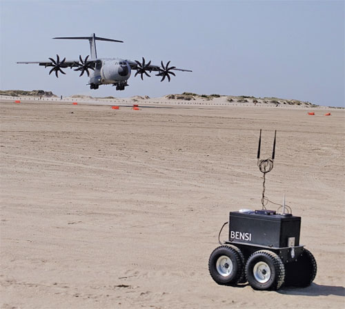
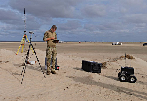
FIGURE 1 shows the BENSI system during a mission at a tactical landing zone with the A400Min the background. FIGURE 2 shows the BENSI system being configured by the operator during a landing preparation.
Figure 1 The autonomous UGV (BENSI) during a mission at a tactical landing zone with the A400M Atlas in the background.Figure 2 The BENSI system being configured by the operator during the beach landing preparation at Rømø, Denmark.
This article details the system’s architecture, the integration of multiple technologies that enable the stringent precision required achieved by GNSS and sensor fusion, self-driving capabilities and its successful deployment in demanding field tests. We present a military graded solution for ensuring tactical airlift safety, enabled by modern, accessible GNSS technology and robotics.
Quantifying runway roughness
Deployable Air Traffic Management (DATM) and Pathfinders are responsible for ensuring the safety of aircraft operations on unpaved runways. They are tasked with assessing the quality of the runway and the Runway Safety Area (RSA) to ensure that the aircraft can land safely. The pilots analyze their assessment and take the final decision to land.
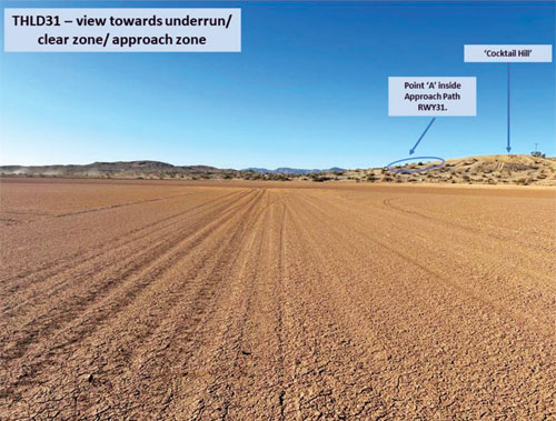
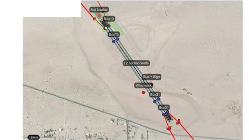
FIGURE 3 is an example of a landing zone having an unpaved runway that needs to be evaluated for landing. FIGURE 4 overviews the landing zone by mapping and indicating features of the runway that need to be considered by the pilots. An important aspect of the DATM’s assessment is the runway’s roughness, which is quantified by the EBH.
Figure 3 An example of a tactical landing zone.
For modern military transport aircraft operations, runway roughness assessment is a critical safety parameter. Both major manufacturers — Airbus with its EBH methodology and Boeing with its Boeing Bump Criteria — have developed sophisticated approaches to characterize runway longitudinal roughness profiles. These methods analyze height variations over wavelengths ranging from 5 to 100 meters, requiring vertical measurement precision of ±1 cm. This rigorous assessment is essential to reduce aircraft structural fatigue, minimize maintenance costs, prevent exceedance of design limit loads, and ultimately ensure safe operations. For the A400M specifically, Airbus requires EBH characterization to determine operational limitations of the aircraft’s maximum payload.
Figure 4 A typical mapping of a landing zone showing a condensed overview of DATM’s assessment.
Traditionally, achieving this precision would involve a painstaking survey conducted by specialists using a GNSS survey system mounted on a trolley requiring human guidance along the measurement tracks totaling more than 3 km of length. For military units like the DATM and Pathfinder teams, who often are the first on the ground, this is impractical. They need a system that is rapid, reliable, simple to operate without a surveying background, and robust enough for field conditions.
A GNSS-Centric design
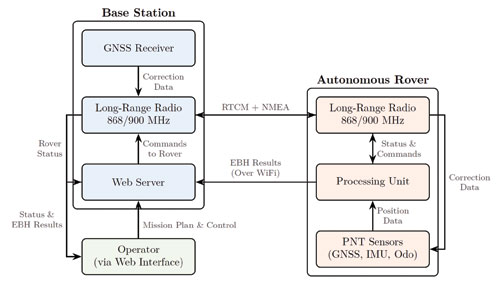
Our solution is a two-part system designed for rapid deployment: a portable GNSS base station and autonomous rover. FIGURE 5 shows a schematic overview of the system architecture.
Figure 5 A schematic overview of the system architecture, showing the data (NMEA) and correction (RTCM) flow between the base station, rover and operator.
The base station: The system’s anchor
Housed in a compact, portable case, weighing just 2 kg including tripod and radios (as seen in FIGURE 2), it serves as the operational hub. Once set up on its lightweight tripod, it performs an automatic survey to establish its precise coordinates. Its primary role for positioning is to generate and transmit Radio Technical Commission for Maritime Services (RTCM) 3.x correction data to the rover via a robust long-range radio link (operating in the868/900MHz bands).
Beyond its GNSS duties, the base station acts as a self-contained command center. It hosts a Wi-Fi hotspot and a web server, allowing the operator to connect with any standard tablet, smartphone or laptop. This web interface is used for mission planning, command and control of the rover, and real-time monitoring of survey progress. At the end of the mission, the operator can download the EBH data and additional quality metrics of the runway for analysis such as a summary report of the complete measurement, a gradient analysis, and a runway map highlighting zones with bumps or troughs exceeding the specified criteria.
An autonomous, all-terrain surveyor
The UGV is a lightweight but rugged platform chosen for its durability and open-source software architecture, which allows for deep integration of our custom navigation and control algorithms. The rover has been designed to be able to traverse rough terrain and survive in harsh weather conditions. The UGV consists of two parts, the chassis (11 kg) and the processing payload(8 kg). The heart of the rover is the processing payload, which contains a sophisticated sensor suite designed for high-precision localization and navigation.
■ Primary GNSS receiver. A high-grade, multi-constellation Septentrio receiver with a Calian/Tallysman GNSS antenna provides the main source of positioning information.
■ GNSS heading. A second Calian/Tallysman GNSS antenna, set up in a moving-base configuration, provides degree-accurate true heading, which is critical for maintaining precise track-following.
■ Inertial measurement unit (IMU). An industrial-grade Xsens IMU provides high-frequency data on the rover’s orientation and acceleration, bridging any brief GNSS outages, providing the sensor fusion algorithm with high-rate data, and helping to smooth the final trajectory.
■ Radio communication. The radio modules provide robust long-range communication with the base station operating in the 868/900MHz bands.
■ Wheel odometry. Encoders on the rover’s wheels provide continuous velocity information, acting as a crucial input for the sensor fusion algorithm. All sensor data is fed into an onboard mini-PC running the Robot Operating System, a flexible framework for developing robotic applications.
Path to precision
Achieving centimeter-level accuracy on a moving platform in challenging environments requires more than just a good GNSS receiver. Our approach is built on a robust foundation of sensor fusion and a dual processing strategy using real-time kinematic and post-processing kinematic (RTK/PPK). An extended Kalman filter (EKF) is at the core of the rover’s navigation software. The EKF continuously fuses data from the GNSS receivers, IMU and wheel encoders to produce a single, high-integrity “pose” (position and orientation) estimate.
For runway surveying, we employ two modes of GNSS processing:
RTK. During the mission, the rover uses the RTCM corrections from the base station to compute a centimeter-accurate position in real-time. This is used for autonomous navigation, allowing the rover to follow its generated mission plan configured by the operator with high precision.
PPK. While RTK provides excellent real-time results, the most demanding applications benefit from post-processing. Both the rover and the base station log all raw GNSS observables during the mission. After the survey is complete, these raw data files are processed together which allows for more rigorous quality control and can often resolve ambiguities or fix cycle slips that were not solvable in real-time, providing the definitive, highest accuracy trajectory for the EBH analysis.
A final crucial step is extracting the height profile for each EBH track and subsequently transforming and reformatting this data for Airbus’ AssurTool. The step also is automated and carried out by the software. It takes care of the following:
■ The conversion of the geodetic coordinates (latitude, longitude, and height above the World Geodetic System 1984 [WGS84] ellipsoid) to Universal Transverse Mercator plane coordinates and orthometric heights (heights relative to a geoid).
■ The extraction of the height profile of each EBH track.
■ Quality control of the precision of the height profile flags tracks that do not meet the required accuracy or show inconsistencies.
■ The transformation and reformatting of this data for Airbus’ AssurTool.
Self-driving capabilities
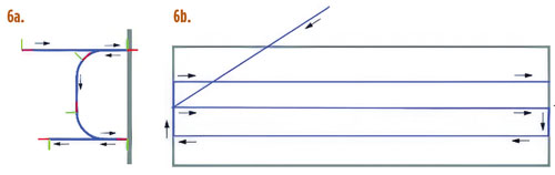
The rover uses a navigation framework with a custom planner for generating smooth, curved paths that match the rover’s turning capabilities and steers the rover using a controller based on the Regulated Pure Pursuit tracking algorithm. A specialized lane-generation algorithm creates optimal survey patterns from runway corner points, with behavior-tree recovery strategies for robust operation.
FIGURE 6 shows a typical EBH survey pattern generated from the mission plan and executed by the rover and a depiction of how the rover plans the smooth curved path between the lanes.
Figure 6 Features of the navigation framework used for planning the EBH tracks. (a) A typical EBH survey pattern generated from the mission plan and executed by the rover. (b) A depiction of how the rover plans the smooth curved path between the lanes.
A streamlined workflow
The system was designed from the ground up to be operated by non-surveyors. A typical mission workflow is as follows:
Setup. The operator places the base station on a tripod near the runway and unfolds the rover. The entire hardware setup takes less than 10 minutes.
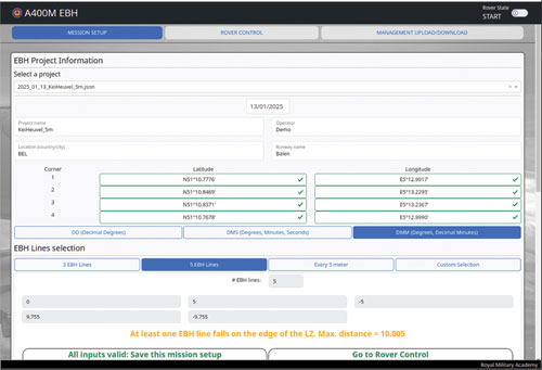
Mission planning. Using a ruggedized tablet (or any other device with a web browser), the operator connects to the base station’s WiFi and opens the web interface. They define the runway by entering the coordinates of the runway’s corners. The software automatically calculates the EBH lines based on the required spacing. FIGURE 7a shows the user interface displayed on a tablet, showing the EBH mission configuration page.
Figure 7a The user interface displayed on a tablet, showing the EBH mission configuration.
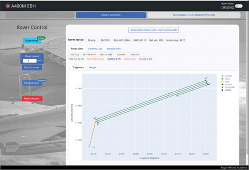
Execution. The operator initiates the mission, and the UGV autonomously navigates to the start of the first line and begins the survey. The operator can monitor and control the rover’s progress, position, and GNSS quality status in real-time on the web interface. FIGURE 7b shows the user interface displayed on a tablet, showing the rover control, the real-time status of the UGV and the measurements.
Figure 7b The tablet showing the rover control and the real-time status of the UGV and the EBH results.
Data retrieval. Upon completion, the rover returns to the base station. The system automatically processes the data, producing downloadable files formatted for direct import into Airbus’ AssurTool and additional useful quality metrics for the operator. These consist of a summary report of the complete measurement, a gradient analysis, and a runway map highlighting zones with bumps or troughs exceeding the specified criteria.
Analyzing the data
Once the rover completes its survey and returns to the base station, the system automatically initiates post-processing of the collected data. This critical step validates the quality of every measurement and generates operator-ready outputs for both Airbus’ AssurTool and field assessment.
The post-processing pipeline applies rigorous quality criteria to each survey line. Lines failing these criteria are automatically flagged with detailed diagnostics explaining the cause.
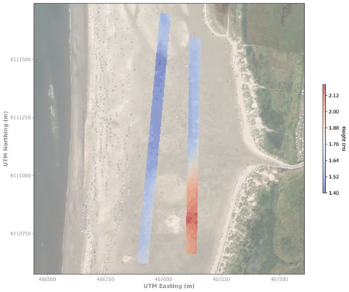
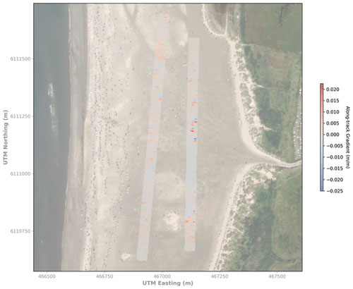
For operational decision-making, the system generates a comprehensive visualization report. The operators receive planimetric maps showing the height profile plots and a detailed gradient analysis identifying critical slope transitions. A key capability is the generation of a 3D interpolated height map of the entire runway surface. This color-coded surface map provides an intuitive view of the runway’s topography, clearly highlighting zones with excessive bumps, depressions, or gradient anomalies that facilitates the assessment of the runway.
These analysis reports are accessible through the web interface for immediate download to the operator’s tablet. FIGURES 8 shows examples of the visualization report.
Figure 8a 2D height and gradient contour maps of two surfaces generated by the BENSI system. (a) A height contour map of two landing zone (LZ) surfaces automatically generated by the BENSI system. Figure 8b A gradient contour map of two LZ surfaces automatically generated by the BENSI system.
Proven performance
The UGV system is a mature prototype that has been validated in numerous international military exercises. It has successfully surveyed tactical landing zones in varied environments, from the desert strips of Yuma, Arizona, and 29 Palms, California, to the sandy shores of Denmark and fields in France, Portugal and Italy. In all tests, the system has consistently delivered the sub-centimeter height precision required for A400M EBH certification.
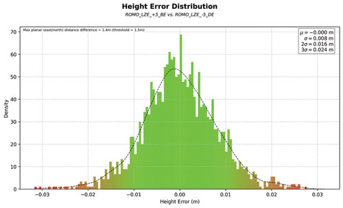
2025 Rømø Head-to-Head Trial.During beach-landing preparations in August 2025, our autonomous rover and a manual system (human-guided trolley) using a professional GNSS survey system ran side-by-side on a 1 000m landing zone on the Rømø beach in Denmark. The BENSI solution matched the manual survey system height profile with a standard deviation of 8mm and demonstrated significantly better lane-tracking consistency (mean deviation: 8,5 cm vs 16 cm and deviation error: 3 cm vs 9 cm). FIGURE 9 shows the height-error distribution between the BENSI system and the manual survey system at Rømø, Denmark.
Figure 9 Height-error distribution between the BENSI system and the manual survey system at Rømø, Denmark.
Rapid humanitarian response
While BENSI was conceived for tactical airlift operations, its capabilities extend naturally to humanitarian assistance and disaster-relief missions. Belgium’s civil rapid-response unit Belgian First Aid & Support Team (B-FAST) routinely deploys doctors, paramedics, firefighters, and other professionals worldwide following earthquakes, floods, or epidemics. Leveraging the A400M’s ability to land on short, unpaved strips away from congested or contested airfields drastically cuts transit times — but only if the runway’s condition can be certified quickly.
The BENSI systems enables a DATM team to quickly relay an EBH report and awareness map of the immediate area to the inbound aircrew. This rapid assessment unlocks critical early access for life-saving medical supplies and personnel when every hour counts.
Conclusion and the Road Ahead
The fusion of autonomous robotics and high-precision GNSS offers a powerful solution to the critical challenge of certifying unpaved runways. Our system saves valuable time, reduces the burden on specialized personnel, and provides objective, high-quality data that directly enhances the safety of tactical airlift operations.
Development is ongoing. Our current efforts focus on several key areas:
■ Improving navigation in degraded environments. We are exploring tighter coupling between the GNSS and IMU to provide more robust navigation through areas of poor satellite visibility.
■ RSA assessment. We are experimenting with integrating a lidar sensor to generate a 3D point cloud of the runway and its surroundings. This will automate obstacle detection and the assessment of the RSA, though we are carefully working to mitigate potential electromagnetic interference from the lidar that can interfere with GNSS reception.
■ Handheld corner point device. To further improve absolute accuracy, we are developing a small, handheld device that uses RTK corrections from the base station, allowing operators to mark the runway corners with centimeter-level precision.
This project demonstrates a clear application of GNSS technology in a demanding military aviation context, with broader implications for any field requiring rapid and precise surface profiling, from civil engineering to disaster response.
Development Team
■ Pieterjan De Meulemeester ([email protected]) is a Ph.D. research engineer at the RMA of Belgium.
■ Alain Muls ([email protected]) is professor at the RMA of Belgium. He teaches the courses Military Satellite Based Positioning andMilitary Geodesy.
■ Jarno Van Audenhoven ([email protected]) is a Robotics Development and Research Engineer at the RMA of Belgium.
■ Pascal De Kimpe is a technician at the RMA of Belgium.
■ The BENSI system was developed by the R&D team at the RMA of Belgium in collaboration with Belgian Defense. The system has been successfully field-tested during international military exercises and is being evaluated for operational deployment.
All photos courtesy of BENSI Development Team of the Royal Military Academy of Belgium
The European Union PAVE-SCAN project aims to build European GNSS-based and AI-driven technologies to detect and assess roadway pavement problems.
The proposed project aims for the development to market (TRL8-9) of European GNSS-based integrated low-cost sensor technologies and artificial-intelligence-driven open-architecture software solution — machine learning (ML) and machine vision (MV) — for the detection, classification and georeferencing of roadway pavement surface anomalies, and for the low-cost assessment of roadway pavements using participatory sensing.
The proposed system is of practical importance because it provides continuous information about roadway pavement surface anomalies — valuable for efficiently monitoring the transport infrastructure and for public safety. The vision for roadway condition assessment using smartphone-like technology is under the hypothesis that such technology can be used for crowd-sourced data collection and analysis in GIS-based pavement management systems (PMS).
“The developed technology and related transport informatics are disruptive technologies that have the potential to reshape the transport and infrastructure industries,” according to the project description.
Near-real-time analysis and classification of roadway anomalies
WP3,WP4,WP5
2
Geospatial mapping of transport infrastructure, roadway anomalies and condition-assessment heatmaps
WP3,WP4,WP5
3
Geospatial mapping of transport infrastructure, roadway anomalies and condition-assessment heatmaps
WP3,WP4,WP5
4
Improved roadway management practices, prioritisation of public works & lower costs
WP4
5
Reduction in the transport-related environmental footprint through improved O&M of transport infrastructure and of mass transit
WP4,WP6,WP7
6
Reduction in roadway-assessment costs by utilization of a fleet of vehicles/buses as participatory sensors
WP5,WP6,WP7
7
Integration with national transport initiatives (e.g., National Single Access Point), & with Digital Twin platforms, for dynamically updated roadway-condition models, and improvements in transport safety through roadway improvements
WP4, WP5
8
Open-access data and APIs
WP1, WP8
9
Product to market and ‘Product as a Service’ (PaaS) business model